EP3184373A1 - Verfahren und anordnung zur stromversorgung von elektrischen verbrauchern eines kraftfahrzeugs - Google Patents
Verfahren und anordnung zur stromversorgung von elektrischen verbrauchern eines kraftfahrzeugs Download PDFInfo
- Publication number
- EP3184373A1 EP3184373A1 EP15307109.7A EP15307109A EP3184373A1 EP 3184373 A1 EP3184373 A1 EP 3184373A1 EP 15307109 A EP15307109 A EP 15307109A EP 3184373 A1 EP3184373 A1 EP 3184373A1
- Authority
- EP
- European Patent Office
- Prior art keywords
- rails
- motor vehicle
- electrical conductors
- aluminum
- electrical
- Prior art date
- Legal status (The legal status is an assumption and is not a legal conclusion. Google has not performed a legal analysis and makes no representation as to the accuracy of the status listed.)
- Granted
Links
Images

Classifications
-
- B—PERFORMING OPERATIONS; TRANSPORTING
- B60—VEHICLES IN GENERAL
- B60R—VEHICLES, VEHICLE FITTINGS, OR VEHICLE PARTS, NOT OTHERWISE PROVIDED FOR
- B60R16/00—Electric or fluid circuits specially adapted for vehicles and not otherwise provided for; Arrangement of elements of electric or fluid circuits specially adapted for vehicles and not otherwise provided for
- B60R16/02—Electric or fluid circuits specially adapted for vehicles and not otherwise provided for; Arrangement of elements of electric or fluid circuits specially adapted for vehicles and not otherwise provided for electric constitutive elements
- B60R16/03—Electric or fluid circuits specially adapted for vehicles and not otherwise provided for; Arrangement of elements of electric or fluid circuits specially adapted for vehicles and not otherwise provided for electric constitutive elements for supply of electrical power to vehicle subsystems or for
Definitions
- the invention relates to a method for powering electrical consumers of a motor vehicle, in which at least two existing of electrically conductive material, existing in the motor vehicle components are used, which are connected electrically connected to the consumer, electrical conductors and in which the components be connected in the position of use with a voltage source of the motor vehicle and on an arrangement produced by the method ( DE 102 20 303 A1 ).
- the electrical lines mounted in a motor vehicle - referred to below as "vehicle” for example - are combined into a unit, for example in so-called cable harnesses or cable strands
- a unit for example in so-called cable harnesses or cable strands
- it may be an energy store or a battery.
- the electrical conductors of a cable harness have different lengths and different cross sections. Because of the usually large number of individual, to be joined to a unit ladder is not only the production of a wiring harness, but also its installation in the vehicle consuming if, for example, consumers located in the rear should be connected to the battery.
- the invention has for its object to make the initially described method and the arrangement made with the same so that the conductors connected to the consumers can be easily connected to be used in the vehicle, electrically conductive components that are themselves simply constructed.
- Aluminum or an aluminum alloy can be used for the rails and the conductors.
- the rails are components which, in addition to all the other fittings and equipment of the vehicle, are installed in the same.
- At least two rails made of aluminum are introduced into the vehicle, which have a relatively low weight because of their material aluminum. They can be easily mounted in a suitable location in a vehicle and connected to the battery of the same electrically conductive.
- the rails may possibly be advantageously formed prior to their assembly in their course so that they are adapted to the shape of a vehicle at the mounting location. The installation of the rails is thereby substantially facilitated.
- the rails are equipped by way of prefabrication along their entire length with connection points, which can also be welded to existing aluminum and therefore light electrical conductor. This is particularly simple in that at the connection points at least recesses are mounted in the rails, in which the conductors can be used with their front ends.
- the recesses are advantageously designed so that the conductors can not move laterally in the same.
- the depressions advantageously have an approximately circular clear width and a circumferential wall which represents a boundary serving for an electrical conductor inserted into a recess.
- the electrical conductor is then each guided so that it can not dodge in the radial direction.
- the electrical conductors can be embodied as solid conductors or as stranded conductors consisting of individual wires.
- the ends of the stranded conductors are advantageously pretreated in such a way that the individual conductors are connected to one another in an electrically conductive manner in a one-part body.
- the wells can be advantageously formed as sleeves or cups, which are closed on one side by a bottom formed by the material of the respective rail.
- connection points can also be designed as through holes into which the ends the electrical conductors to be connected to the rails can be easily inserted.
- the rails are advantageously all around and over their entire length surrounded by an insulation, by which they face the superstructures of the vehicle and overall are covered safe to touch.
- Suitable insulating materials are for example silicone, polyethylene, polyurethane, polyamide, polypropylene and ceramic.
- the locations of the connection points of the rails to which prior to their installation, no electrical conductors are connected, are expediently marked on the outside of the insulation.
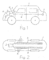
- FIG. 1 schematically illustrated vehicle 1 should be a car. It has in the illustrated embodiment arranged in the engine compartment battery 2 and a plurality of electrical loads 3, of which only three located at different positions in the vehicle 1 are shown as circles. All consumers 3 are electrically connected to the battery 2 via insulated electrical conductors 4 made of aluminum.
- the vehicle 1 may also have a different shape than a car and it may also have fewer or more than four wheels. It can also be, for example, a van or a bus.
- Fig. 2 only the bottom area of the vehicle 1 is shown schematically. Any structures are omitted for clarity.
- two rails 5 and 6 are in the illustrated embodiment attached, which extend substantially over the entire length of the vehicle 1.
- the rails 5 and 6 are advantageously mounted in the floor area of the vehicle 1. They can also be fitted with the appropriate protective cover on the outside of the vehicle floor. In principle, more than two rails can be arranged in or on the vehicle 1, which are optionally electrically connected to one another in a suitable manner.
- Each rail 5 and 6 is connected at one end to one of the poles of the battery 2.
- the battery 2 is arranged in the illustrated embodiment in the region of one end of the vehicle 1.
- the rails 5 and 6 may be formed in one piece according to the drawing representation.
- the rails 5 and 6 may each consist of two parts, which extend on different sides of the battery 2 each to an end portion of the vehicle 1.
- the rails 5 and 6 have over their entire length at a distance from each other arranged connection points 7 and 8, to which the leading to the consumers 3 electrical conductors 4 can be connected directly or indirectly.
- the leading to the consumers 3 electrical conductors 4 can be connected individually to two complementary connection points 7 and 8 of the different polarities having rails 5 and 6. It is also possible to combine two or more electrical conductors 4 and to connect together directly to two complementary connection points 7 and 8. This is particularly suitable for the connection of located in the rear area or in the engine compartment of the vehicle 1 larger number of consumers 3.
- the rails 5 and 6 have advantageously a rectangular cross-section, as it is in Fig. 3 is shown. They are surrounded over their entire length by an insulation 9, which may advantageously consist of the materials described in the foregoing.
- the electrical conductors 4 may be designed as a solid conductor or as a stranded conductor. They are surrounded by a jacket 10 made of insulating material, the for connecting a conductor to a rail accordingly Fig. 4 at the end of it is removed. If the conductor 4 is designed as consisting of individual wires stranded conductor, its frontal end is appropriately pretreated prior to assembly, that on the same a one-piece body is formed, in which all the individual wires are electrically connected to each other. This can be done, for example, by melting the end of the stranded conductor or the ends of all individual conductors thereof.
- the rails 5 and 6 have - as already mentioned - on their entire length connection points 7 and 8, which are arranged at a distance from each other.
- the connection points 7 and 8 are at least designed as in the rails 5 and 6 recesses 11, according to Fig. 5 advantageously have an approximately circular clear width.
- the depressions 11 can advantageously be designed as sleeves or wells, which may be holes closed by a bottom 12.
- the bottom 12 is formed by the material of the rails 5 and 6.
- the depressions 11 have a wall 13 which extends in its circumferential direction and which serves as a boundary acting in the radial direction for an electrical conductor 4 inserted into a depression.
- connection points 7 and 8 can according to Fig. 7 be designed as through holes 14. At least part of the connection points 7 and 8 may be a through hole.
- the electrical conductors 4 can be connected in this sense at different connection points of the rails 5 and 6 with the same before they are mounted in the vehicle 1. But you can also be connected to the rails 5 and 6, if they are already mounted in the vehicle 1.
- the rails 5 and 6 surrounding insulation 9 is suitably provided with markings which mark the positions of the connection points 7 and 8 respectively. This is also true for the case that subsequent additional electrical conductor 4 to be connected to the rails 5 and 6.
Landscapes
- Engineering & Computer Science (AREA)
- Mechanical Engineering (AREA)
- Connections Effected By Soldering, Adhesion, Or Permanent Deformation (AREA)
- Body Structure For Vehicles (AREA)
Abstract
Description
- Die Erfindung bezieht sich auf ein Verfahren zur Stromversorgung von elektrischen Verbrauchern eines Kraftfahrzeugs, bei welchem mindestens zwei aus elektrisch leitendem Material bestehende, im Kraftfahrzeug vorhandene Bauteile verwendet werden, an welche mit den Verbrauchern verbundene, elektrische Leiter elektrisch leitend angeschlossen werden und bei welchem die Bauteile in Gebrauchslage mit einer Spannungsquelle des Kraftfahrzeugs verbunden werden sowie auf eine mit dem Verfahren hergestellte Anordnung (
DE 102 20 303 A1 ). - In bekannter Technik sind die in einem Kraftfahrzeug - im Folgenden kurz Fahrzeug" genannt - montierten elektrischen Leitungen beispielsweise in sogenannten Kabelbäumen bzw. Kabelsträngen jeweils zu einer Einheit zusammengefaßt. Die elektrischen Verbraucher eines Fahrzeugs sind über die elektrischen Leitungen mit der Spannungsquelle desselben verbunden, bei der es sich beispielsweise um einen Energiespeicher oder um eine Batterie handeln kann. Die Spannungsquelle wird im Folgenden als Batterie" bezeichnet. Die elektrischen Leiter eines Kabelbaums haben unterschiedliche Längen und unterschiedliche Querschnitte. Wegen der meist großen Anzahl einzelner, zu einer Einheit zu verbindenden Leiter ist nicht nur die Herstellung eines Kabelbaums, sondern auch seine Verlegung im Fahrzeug aufwendig, wenn beispielsweise im Heckbereich befindliche Verbraucher mit der Batterie verbunden werden sollen.
- Bei dem bekannten Verfahren nach der eingangs erwähnten
DE 102 20 303 A1 werden der Kabelbaum bzw. die Kabelbäume durch eine Bespeisungsplattform ersetzt, die aus mindestens zwei mit der Batterie eines Fahrzeugs elektrisch leitend verbundenen Karosserieelementen besteht. Die mit den elektrischen Verbrauchern verbundenen elektrischen Leiter werden an die Bespeisungsplattform angeschlossen. Die Schrift befaßt sich im Wesentlichen mit dem Aufbau und der Ausgestaltung der Bespeisungsplattform. Über die Art und Weise, wie die Leiter an deren Elemente angeschlossen sind, werden in der Schrift keine Angaben gemacht. - Der Erfindung liegt die Aufgabe zugrunde, das eingangs geschilderte Verfahren und die mit demselben hergestellte Anordnung so zu gestalten, daß die mit den Verbrauchern verbundenen Leiter einfach an im Fahrzeug einzusetzende, elektrisch leitende Bauteile angeschlossen werden können, die selbst einfach aufgebaut sind.
- Diese Aufgabe wird gemäß der Erfindung dadurch gelöst,
- daß als Bauteile aus Aluminium oder aus einer Aluminiumlegierung bestehende Schienen mit etwa rechteckigem Querschnitt im Fahrzeug angeordnet werden, die auf ihrer ganzen Länge mit mit Abstand zueinander angebrachten, vorbereiteten Anschlußpunkten zum elektrisch leitenden Anschließen von aus Aluminium oder aus einer Aluminiumlegierung bestehenden elektrischen Leitern ausgerüstet werden, welche zumindest als Vertiefungen im Material der Schienen ausgeführt sind, und
- daß die elektrischen Leiter mit ihren stirnseitigen Enden in die Vertiefungen der Schienen eingebracht und durch Schweißen elektrisch leitend mit denselben verbunden werden.
- Für die Schienen und die Leiter können Aluminium oder eine Aluminiumlegierung eingesetzt werden. Der Einfachheit halber wird in der folgenden Beschreibung nur Aluminium erwähnt, stellvertretend auch für eine Aluminiumlegierung. Bei den Schienen handelt es sich um Bauteile, die zusätzlich zu allen anderen Einbauten und Geräten des Fahrzeugs in demselben angebracht werden.
- Von wesentlicher Bedeutung für das Verfahren und die Anordnung ist, daß sowohl für die Schienen als auch für die Leiter Aluminium eingesetzt ist, wodurch das Gewicht der elektrischen Ausrüstung gegenüber herkömmlichen Ausrüstungen, die im Wesentlichen Kupfer als elektrisch leitendes Material aufweisen, erheblich reduziert ist. Wesentlich ist außerdem die Art der elektrischen Verbindung zwischen Schienen und Leitern, für welche keine gesonderten Kontaktteile eingesetzt werden. Die Leiter werden an den Anschlußpunkten vielmehr direkt mit den Schienen verschweißt.
- Bei diesem Verfahren werden mindestens zwei aus Aluminium bestehende Schienen im Fahrzeug eingebracht, die wegen ihres Materials Aluminium ein relativ geringes Gewicht haben. Sie können auf einfache Art und Weise an geeigneter Stelle in einem Fahrzeug montiert und mit der Batterie desselben elektrisch leitend verbunden werden. Die Schienen können gegebenenfalls mit Vorteil vor ihrer Montage in ihrem Verlauf so geformt werden, daß sie der Form eines Fahrzeugs an der Montagestelle angepaßt sind. Die Montage der Schienen wird dadurch wesentlich erleichtert. Die Schienen sind im Wege der Vorfertigung auf ihrer ganzen Länge mit Anschlußpunkten ausgerüstet, an denen ebenfalls aus Aluminium bestehende und daher leichte elektrische Leiter angeschweißt werden können. Das ist dadurch besonders einfach, daß an den Anschlußpunkten zumindest Vertiefungen in den Schienen angebracht sind, in welche die Leiter mit ihren stirnseitigen Enden eingesetzt werden können. Die Vertiefungen sind mit Vorteil so ausgeführt, daß die Leiter in denselben nicht seitlich ausweichen können.
- Die Vertiefungen haben mit Vorteil eine etwa kreisförmige lichte Weite und eine in Umfangsrichtung verlaufende Wandung, welche eine für einen in eine Vertiefung eingesetzten elektrischen Leiter dienende Begrenzung darstellt. Der elektrische Leiter ist dann jeweils so geführt, daß er nicht in radialer Richtung ausweichen kann.
- Die elektrischen Leiter können als Massivleiter oder als aus Einzeldrähten bestehende Litzenleiter ausgeführt sein. Die Enden der Litzenleiter werden mit Vorteil so vorbehandelt, daß die Einzelleiter in einem einteiligen Körper elektrisch leitend miteinander verbunden sind.
- In diesem Sinne können die Vertiefungen mit Vorteil als Hülsen oder Näpfe ausgebildet werden, die durch einen vom Material der jeweiligen Schiene gebildeten Boden einseitig verschlossen sind.
- In einer weiteren vorteilhaften Ausgestaltung der Schienen können deren Anschlußpunkte auch als Durchgangslöcher ausgeführt sein, in welche die Enden der mit den Schienen zu verbindenden elektrischen Leiter sehr einfach eingesteckt werden können.
- Die Schienen sind mit Vorteil rundum und über ihre ganze Länge von einer Isolierung umgeben, durch welche sie gegenüber den Aufbauten des Fahrzeugs und insgesamt
berührungssicher abgedeckt sind. Geeignete Isoliermaterialien sind beispielsweise Silikon, Polyethylen, Polyurethan, Polyamid, Polypropylen und Keramik. Die Stellen der Anschlußpunkte der Schienen, an denen vor ihrer Montage noch keine elektrischen Leiter angeschlossen sind, werden zweckmäßig außen auf der Isolierung markiert. - Das Verfahren und die Anordnung nach der Erfindung werden anhand der Zeichnungen in Ausführungsbeispielen erläutert.
- Es zeigen:
-
Fig. 1 in schematischer Darstellung eine Seitenansicht eines Fahrzeugs. -
Fig. 2 ebenfalls in schematischer Darstellung eine Anordnung nach der Erfindung. -
Fig. 3 bis 7 Einzelheiten der Anordnung nachFig. 2 in vergrößerten Darstellungen. - Die
Fig. 6 und 7 sind dabei zwei unterschiedliche Querschnitte derFig. 5 entlang der Linie VI - VI. - Das in
Fig. 1 schematisch dargestellte Fahrzeug 1 soll ein PKW sein. Es hat im dargestellten Ausführungsbeispiel eine im Motorraum angeordnete Batterie 2 und eine Vielzahl von elektrischen Verbrauchern 3, von denen nur drei an unterschiedlichen Positionen im Fahrzeug 1 befindliche als Kreise eingezeichnet sind. Alle Verbraucher 3 sind über aus Aluminium bestehende isolierte elektrische Leiter 4 elektrisch leitend mit der Batterie 2 verbunden. Das Fahrzeug 1 kann auch eine andere Form als ein PKW haben und es kann auch weniger oder mehr als vier Räder aufweisen. Es kann beispielsweise auch ein Transporter oder ein Bus sein. - In
Fig. 2 ist nur der Bodenbereich des Fahrzeugs 1 schematisch dargestellt. Jedwede Aufbauten sind der Übersichtlichkeit halber fortgelassen. In diesem Bodenbereich sind im dargestellten Ausführungsbeispiel zwei Schienen 5 und 6 angebracht, die sich im wesentlichen über die ganze Länge des Fahrzeugs 1 erstrecken. Die Schienen 5 und 6 werden mit Vorteil im Bodenbereich des Fahrzeugs 1 montiert. Sie können auch mit entsprechender schützender Abdeckung außen am Boden des Fahrzeugs angebracht werden. Es können grundsätzlich auch mehr als zwei Schienen im bzw. am Fahrzeug 1 angeordnet werden, die gegebenenfalls in geeigneter Weise elektrisch miteinander verbunden sind. Jede Schiene 5 bzw. 6 ist mit einem Ende mit einem der Pole der Batterie 2 verbunden. - Die Batterie 2 ist im dargestellten Ausführungsbeispiel im Bereich eines Endes des Fahrzeugs 1 angeordnet. Die Schienen 5 und 6 können entsprechend der zeichnerischen Darstellung jeweils einstückig ausgebildet sein. Wenn die Batterie 2 beispielsweise im mittleren Bereich des Fahrzeugs 1 angebracht ist, können die Schienen 5 und 6 auch jeweils aus zwei Teilen bestehen, die sich auf unterschiedlichen Seiten der Batterie 2 jeweils bis zu einem Endbereich des Fahrzeugs 1 erstrecken.
- Die Schienen 5 und 6 weisen auf ihrer ganzen Länge mit Abstand zueinander angeordnete Anschlußpunkte 7 bzw. 8 auf, an welche die zu den Verbrauchern 3 führenden elektrischen Leiter 4 direkt oder indirekt angeschlossen werden können. Die zu den Verbrauchern 3 führenden elektrischen Leiter 4 können einzeln an zwei komplementäre Anschlußpunkte 7 und 8 der unterschiedliche Polaritäten aufweisende Schienen 5 und 6 angeschlossen werden. Es ist auch möglich, zwei oder mehr elektrische Leiter 4 zusammenzufassen und gemeinsam direkt an zwei komplementäre Anschlußpunkte 7 und 8 anzuschließen. Das bietet sich insbesondere für den Anschluß der im Heckbereich oder im Motorraum des Fahrzeugs 1 befindlichen größeren Anzahl von Verbrauchern 3 an.
- Die Schienen 5 und 6 haben mit Vorteil einen rechteckigen Querschnitt, so wie es in
Fig. 3 dargestellt ist. Sie sind auf ihrer ganzen Länge von einer Isolierung 9 umgeben, die mit Vorteil aus den im Vorangehenden beschriebenen Materialien bestehen kann. - Die elektrischen Leiter 4 können als Massivleiter oder auch als Litzenleiter ausgeführt sein. Sie sind von einem Mantel 10 aus Isoliermaterial umgeben, der zum Anschluß eines Leiters an eine Schiene entsprechend
Fig. 4 am Ende desselben entfernt ist. Wenn der Leiter 4 als aus Einzeldrähten bestehender Litzenleiter ausgeführt ist, wird sein stirnseitiges Ende vor der Montage zweckmäßig so vorbehandelt, daß an demselben ein einteiliger Körper gebildet ist, in welchem alle Einzeldrähte elektrisch leitend miteinander verbunden sind. Das kann beispielsweise durch Aufschmelzen des Endes des Litzenleiters bzw. der Enden aller Einzelleiter desselben erfolgen. - Die Schienen 5 und 6 haben - wie schon erwähnt - auf ihrer ganzen Länge Anschlußpunkte 7 bzw. 8, die mit Abstand zueinander angeordnet sind. Die Anschlußpunkte 7 und 8 sind zumindest als in den Schienen 5 und 6 angebrachte Vertiefungen 11 ausgeführt, die gemäß
Fig. 5 mit Vorteil eine etwa kreisförmige lichte Weite haben. Die Vertiefungen 11 können mit Vorteil als Hülsen bzw. Näpfe ausgeführt sein, bei welchen es sich um durch einen Boden 12 verschlossene Löcher handeln kann. Der Boden 12 wird vom Material der Schienen 5 und 6 gebildet. Die Vertiefungen 11 haben eine in ihrer Umfangsrichtung verlaufende Wandung 13, welche als in radialer Richtung wirkende Begrenzung für einen in eine Vertiefung eingesetzten elektrischen Leiter 4 dient. - Die Anschlußpunkte 7 und 8 können gemäß
Fig. 7 auch als Durchgangslöcher 14 ausgeführt sein. Zumindest ein Teil der Anschlußpunkte 7 und 8 kann ein Durchgangsloch sein. - Das Verfahren nach der Erfindung wird beispielsweise wie folgt durchgeführt:
- Die Schienen 5 und 6 werden in der erforderlichen Länge und Form im Wege der Vorfertigung mit den als Vertiefungen 11 und/oder Durchgangslöchern 14 ausgeführten Anschlußpunkten 7 und 8 versehen. Ein elektrischer Leiter 4 wird zu seiner elektrisch leitenden Verbindung mit einer der Schienen 5 oder 6 in eine Vertiefung 11 bzw. in ein Durchgangsloch 14 derselben eingesetzt und durch Zufuhr von ausreichender Wärme mit der Schiene 5 bzw. 6 verschweißt. Dabei werden auf den Oberflächen von Schienen 5 bzw. 6 und elektrischen Leitern 4 vorhandene dünne Oxidschichten aufgebrochen, so daß sich einwandfreie, elektrisch leitende Verbindung zwischen dem Leiter 4 und der jeweiligen Schiene 5 bzw. 6 ergibt.
- Die elektrischen Leiter 4 können in diesem Sinne an unterschiedlichen Anschlußpunkten der Schienen 5 und 6 mit denselben verbunden werden, bevor dieselben im Fahrzeug 1 montiert werden. Sie können aber auch erst dann an die Schienen 5 und 6 angeschlossen werden, wenn dieselben bereits im Fahrzeug 1 montiert sind. Dazu ist die die Schienen 5 bzw. 6 umgebende Isolierung 9 zweckmäßig mit Markierungen versehen, welche die Positionen der Anschlußpunkte 7 bzw. 8 markieren. Das gilt mit Vorteil auch für den Fall, daß nachträgliche zusätzliche elektrische Leiter 4 an die Schienen 5 und 6 angeschlossen werden sollen.
Claims (4)
- Verfahren zur Stromversorgung von elektrischen Verbrauchern eines Kraftfahrzeugs, bei welchem mindestens zwei aus elektrisch leitendem Material bestehende, im Kraftfahrzeug vorhandene Bauteile verwendet werden, an welche mit den Verbrauchern verbundene, elektrische Leiter elektrisch leitend angeschlossen werden und bei welchem die Bauteile in Gebrauchslage mit einer Spannungsquelle des Kraftfahrzeugs verbunden werden, dadurch gekennzeichnet,- daß als Bauteile aus Aluminium oder aus einer Aluminiumlegierung bestehende Schienen (5,6) mit etwa rechteckigem Querschnitt im Kraftfahrzeug (1) angeordnet werden, die auf ihrer ganzen Länge mit mit Abstand zueinander angebrachten, vorbereiteten Anschlußpunkten (7,8) zum elektrisch leitenden Anschließen von aus Aluminium oder aus einer Aluminiumlegierung bestehenden elektrischen Leitern (4) ausgerüstet werden, welche zumindest als Vertiefungen (11,14) im Material der Schienen (5,6) ausgeführt sind, und- daß die elektrischen Leiter (4) mit ihren stirnseitigen Enden in die Vertiefungen (11,14) der Schienen (5,6) eingebracht und durch Schweißen elektrisch leitend mit denselben verbunden werden.
- Anordnung zur Durchführung des Verfahrens nach Anspruch 1, dadurch gekennzeichnet, daß die Vertiefungen (11,14) jeweils eine etwa kreisförmige lichte Weite und eine in Umfangsrichtung verlaufende Wandung (13) als begrenzende Fläche für einen in einer Vertiefung (11,14) angeordneten elektrischen Leiter (4) aufweisen.
- Anordnung nach Anspruch 2, dadurch gekennzeichnet, daß die Vertiefungen (11) als durch einen Boden (12) verschlossene Hülsen bzw. Näpfe ausgeführt sind.
- Anordnung zur Durchführung des Verfahrens nach Anspruch 1, dadurch gekennzeichnet, daß die Anschlußpunkte (7,8) zumindest teilweise als Durchgangslöcher (14) ausgeführt sind.
Priority Applications (2)
| Application Number | Priority Date | Filing Date | Title |
|---|---|---|---|
| EP15307109.7A EP3184373B1 (de) | 2015-12-22 | 2015-12-22 | Verfahren und anordnung zur stromversorgung von elektrischen verbrauchern eines kraftfahrzeugs |
| PT153071097T PT3184373T (pt) | 2015-12-22 | 2015-12-22 | Método e conjunto para o fornecimento de energia de consumidores elétricos de um veículo motorizado |
Applications Claiming Priority (1)
| Application Number | Priority Date | Filing Date | Title |
|---|---|---|---|
| EP15307109.7A EP3184373B1 (de) | 2015-12-22 | 2015-12-22 | Verfahren und anordnung zur stromversorgung von elektrischen verbrauchern eines kraftfahrzeugs |
Publications (2)
| Publication Number | Publication Date |
|---|---|
| EP3184373A1 true EP3184373A1 (de) | 2017-06-28 |
| EP3184373B1 EP3184373B1 (de) | 2022-11-09 |
Family
ID=55079984
Family Applications (1)
| Application Number | Title | Priority Date | Filing Date |
|---|---|---|---|
| EP15307109.7A Active EP3184373B1 (de) | 2015-12-22 | 2015-12-22 | Verfahren und anordnung zur stromversorgung von elektrischen verbrauchern eines kraftfahrzeugs |
Country Status (2)
| Country | Link |
|---|---|
| EP (1) | EP3184373B1 (de) |
| PT (1) | PT3184373T (de) |
Citations (5)
| Publication number | Priority date | Publication date | Assignee | Title |
|---|---|---|---|---|
| US20020163219A1 (en) * | 2001-05-01 | 2002-11-07 | Clark Kenneth M. | Modular system for a vehicle |
| DE10220303A1 (de) | 2002-05-07 | 2003-11-20 | Opel Adam Ag | Anordnung zur Spannungsversorgung mindestens eines elektrischen Verbrauchers für ein Fahrzeug |
| DE102011018353A1 (de) * | 2011-04-20 | 2012-10-25 | Auto-Kabel Managementgesellschaft Mbh | Schweißhülse mit Kontaktteil |
| EP2703229A1 (de) * | 2012-08-27 | 2014-03-05 | Nexans | Anordnung zur Stromversorgung von in einem Kraftfahrzeug angeordneten elektrischen Verbrauchern |
| US20150107870A1 (en) * | 2013-10-21 | 2015-04-23 | GM Global Technology Operations LLC | Light weight bus bars, methods of manufacture thereof and articles comprising the same |
-
2015
- 2015-12-22 PT PT153071097T patent/PT3184373T/pt unknown
- 2015-12-22 EP EP15307109.7A patent/EP3184373B1/de active Active
Patent Citations (5)
| Publication number | Priority date | Publication date | Assignee | Title |
|---|---|---|---|---|
| US20020163219A1 (en) * | 2001-05-01 | 2002-11-07 | Clark Kenneth M. | Modular system for a vehicle |
| DE10220303A1 (de) | 2002-05-07 | 2003-11-20 | Opel Adam Ag | Anordnung zur Spannungsversorgung mindestens eines elektrischen Verbrauchers für ein Fahrzeug |
| DE102011018353A1 (de) * | 2011-04-20 | 2012-10-25 | Auto-Kabel Managementgesellschaft Mbh | Schweißhülse mit Kontaktteil |
| EP2703229A1 (de) * | 2012-08-27 | 2014-03-05 | Nexans | Anordnung zur Stromversorgung von in einem Kraftfahrzeug angeordneten elektrischen Verbrauchern |
| US20150107870A1 (en) * | 2013-10-21 | 2015-04-23 | GM Global Technology Operations LLC | Light weight bus bars, methods of manufacture thereof and articles comprising the same |
Non-Patent Citations (1)
| Title |
|---|
| EXOCONTRALTO: "How To Make Mini Buss Bars - Best 2 Deep Cycle Car Audio Batteries - Loud SPL Stereo System Install", 16 December 2009 (2009-12-16), XP054976612, Retrieved from the Internet <URL:https://www.youtube.com/watch?feature=player_embedded&v=Lz7h06JIQpA> [retrieved on 20160614] * |
Also Published As
| Publication number | Publication date |
|---|---|
| PT3184373T (pt) | 2023-02-03 |
| EP3184373B1 (de) | 2022-11-09 |
Similar Documents
| Publication | Publication Date | Title |
|---|---|---|
| DE102012005902B4 (de) | Hochspannungskabel-Führungsstruktur für ein elektrisch angetriebenes Fahrzeug | |
| DE102014010491A1 (de) | Kraftfahrzeug und Aufnahmevorrichtung zur Aufnahme von elektrischen Energiespeicherzellen | |
| EP3528305B1 (de) | Verwendung von antriebsbatterien in kraftfahrzeugen | |
| EP2909123B1 (de) | Überwachung von tragmitteln in aufzugsanlagen | |
| DE102015220115A1 (de) | Elektrisches energieversorgungssystem und herstellungsverfahren für ein solches | |
| EP2806160A1 (de) | Windenergieanlagenrotorblatt mit einer elektrischen Heizeinrichtung und mehreren Blitzschutzleitern | |
| DE102014218559A1 (de) | Mit einem Anschlussstück ausgerüsteter Leiter | |
| EP3534466A1 (de) | Anordnung zur stromverteilung sowie deren kontaktierung und absicherung der abgehenden leitungen | |
| EP3265358B1 (de) | Schienenfahrzeug, verfahren zum antreiben eines schienenfahrzeugs sowie verfahren zur herstellung eines schienenfahrzeugs | |
| DE202015103854U1 (de) | Stromschiene zur Verwendung im Bordnetz oder als Batterieleitung von Fahrzeugen | |
| DE102013203638A1 (de) | Metall-Verbinderprofil, Solarmodul und Verfahren zu dessen Herstellung | |
| DE102013016824A1 (de) | Fahrzeug mit zumindest einer Batterie | |
| DE112014005872T5 (de) | Kabelbaum und Verfahren zum Einführen elektrisch leitfähiger Pfade durch einen Kabelbaum | |
| DE102006049604C5 (de) | Hochstromkabel für Fahrzeuge sowie Kabelkanal zum elektrisch isolierenden Aufnehmen eines solchen Hochstromkabels | |
| EP2217495B1 (de) | Trägerrohr für deckenelemente | |
| WO2022194797A1 (de) | Verteilungssystem für ein bordnetz sowie versorgungsstrang für ein solches verteilungssystem | |
| DE102016201431A1 (de) | Außenelement und Kabelbaum | |
| EP3184373B1 (de) | Verfahren und anordnung zur stromversorgung von elektrischen verbrauchern eines kraftfahrzeugs | |
| DE102009004836B4 (de) | Kabelbaum und Fahrzeugklimaanlage | |
| DE602005000133T2 (de) | Versorgungsrückleitungsvorrichtung für Bordelektronikeinrichtungen | |
| DE102014226081A1 (de) | Schienenfahrzeug mit Akkumulatormodulen | |
| WO2014195133A1 (de) | Fahrzeug, insbesondere schienenfahrzeug | |
| EP2703229B1 (de) | Anordnung zur Stromversorgung von in einem Kraftfahrzeug angeordneten elektrischen Verbrauchern | |
| DE102013222090A1 (de) | Zellkontaktierungssystem, Batteriemodul mit einem Zellkontaktierungssystem und Fahrzeug mit zumindest einem derartigen Batteriemodul | |
| AT16836U1 (de) | Stromschiene mit LEDs |
Legal Events
| Date | Code | Title | Description |
|---|---|---|---|
| PUAI | Public reference made under article 153(3) epc to a published international application that has entered the european phase |
Free format text: ORIGINAL CODE: 0009012 |
|
| STAA | Information on the status of an ep patent application or granted ep patent |
Free format text: STATUS: REQUEST FOR EXAMINATION WAS MADE |
|
| 17P | Request for examination filed |
Effective date: 20161114 |
|
| AK | Designated contracting states |
Kind code of ref document: A1 Designated state(s): AL AT BE BG CH CY CZ DE DK EE ES FI FR GB GR HR HU IE IS IT LI LT LU LV MC MK MT NL NO PL PT RO RS SE SI SK SM TR |
|
| AX | Request for extension of the european patent |
Extension state: BA ME |
|
| RAP1 | Party data changed (applicant data changed or rights of an application transferred) |
Owner name: NEXANS |
|
| STAA | Information on the status of an ep patent application or granted ep patent |
Free format text: STATUS: EXAMINATION IS IN PROGRESS |
|
| 17Q | First examination report despatched |
Effective date: 20180321 |
|
| GRAP | Despatch of communication of intention to grant a patent |
Free format text: ORIGINAL CODE: EPIDOSNIGR1 |
|
| STAA | Information on the status of an ep patent application or granted ep patent |
Free format text: STATUS: GRANT OF PATENT IS INTENDED |
|
| INTG | Intention to grant announced |
Effective date: 20220608 |
|
| GRAS | Grant fee paid |
Free format text: ORIGINAL CODE: EPIDOSNIGR3 |
|
| GRAA | (expected) grant |
Free format text: ORIGINAL CODE: 0009210 |
|
| STAA | Information on the status of an ep patent application or granted ep patent |
Free format text: STATUS: THE PATENT HAS BEEN GRANTED |
|
| AK | Designated contracting states |
Kind code of ref document: B1 Designated state(s): AL AT BE BG CH CY CZ DE DK EE ES FI FR GB GR HR HU IE IS IT LI LT LU LV MC MK MT NL NO PL PT RO RS SE SI SK SM TR |
|
| REG | Reference to a national code |
Ref country code: GB Ref legal event code: FG4D Free format text: NOT ENGLISH |
|
| REG | Reference to a national code |
Ref country code: CH Ref legal event code: EP Ref country code: AT Ref legal event code: REF Ref document number: 1530147 Country of ref document: AT Kind code of ref document: T Effective date: 20221115 |
|
| REG | Reference to a national code |
Ref country code: DE Ref legal event code: R096 Ref document number: 502015016148 Country of ref document: DE |
|
| REG | Reference to a national code |
Ref country code: IE Ref legal event code: FG4D Free format text: LANGUAGE OF EP DOCUMENT: GERMAN |
|
| REG | Reference to a national code |
Ref country code: PT Ref legal event code: SC4A Ref document number: 3184373 Country of ref document: PT Date of ref document: 20230203 Kind code of ref document: T Free format text: AVAILABILITY OF NATIONAL TRANSLATION Effective date: 20230130 |
|
| REG | Reference to a national code |
Ref country code: LT Ref legal event code: MG9D |
|
| REG | Reference to a national code |
Ref country code: NL Ref legal event code: MP Effective date: 20221109 |
|
| PG25 | Lapsed in a contracting state [announced via postgrant information from national office to epo] |
Ref country code: SE Free format text: LAPSE BECAUSE OF FAILURE TO SUBMIT A TRANSLATION OF THE DESCRIPTION OR TO PAY THE FEE WITHIN THE PRESCRIBED TIME-LIMIT Effective date: 20221109 Ref country code: NO Free format text: LAPSE BECAUSE OF FAILURE TO SUBMIT A TRANSLATION OF THE DESCRIPTION OR TO PAY THE FEE WITHIN THE PRESCRIBED TIME-LIMIT Effective date: 20230209 Ref country code: LT Free format text: LAPSE BECAUSE OF FAILURE TO SUBMIT A TRANSLATION OF THE DESCRIPTION OR TO PAY THE FEE WITHIN THE PRESCRIBED TIME-LIMIT Effective date: 20221109 Ref country code: FI Free format text: LAPSE BECAUSE OF FAILURE TO SUBMIT A TRANSLATION OF THE DESCRIPTION OR TO PAY THE FEE WITHIN THE PRESCRIBED TIME-LIMIT Effective date: 20221109 Ref country code: ES Free format text: LAPSE BECAUSE OF FAILURE TO SUBMIT A TRANSLATION OF THE DESCRIPTION OR TO PAY THE FEE WITHIN THE PRESCRIBED TIME-LIMIT Effective date: 20221109 |
|
| PG25 | Lapsed in a contracting state [announced via postgrant information from national office to epo] |
Ref country code: RS Free format text: LAPSE BECAUSE OF FAILURE TO SUBMIT A TRANSLATION OF THE DESCRIPTION OR TO PAY THE FEE WITHIN THE PRESCRIBED TIME-LIMIT Effective date: 20221109 Ref country code: PL Free format text: LAPSE BECAUSE OF FAILURE TO SUBMIT A TRANSLATION OF THE DESCRIPTION OR TO PAY THE FEE WITHIN THE PRESCRIBED TIME-LIMIT Effective date: 20221109 Ref country code: LV Free format text: LAPSE BECAUSE OF FAILURE TO SUBMIT A TRANSLATION OF THE DESCRIPTION OR TO PAY THE FEE WITHIN THE PRESCRIBED TIME-LIMIT Effective date: 20221109 Ref country code: IS Free format text: LAPSE BECAUSE OF FAILURE TO SUBMIT A TRANSLATION OF THE DESCRIPTION OR TO PAY THE FEE WITHIN THE PRESCRIBED TIME-LIMIT Effective date: 20230309 Ref country code: HR Free format text: LAPSE BECAUSE OF FAILURE TO SUBMIT A TRANSLATION OF THE DESCRIPTION OR TO PAY THE FEE WITHIN THE PRESCRIBED TIME-LIMIT Effective date: 20221109 Ref country code: GR Free format text: LAPSE BECAUSE OF FAILURE TO SUBMIT A TRANSLATION OF THE DESCRIPTION OR TO PAY THE FEE WITHIN THE PRESCRIBED TIME-LIMIT Effective date: 20230210 |
|
| PG25 | Lapsed in a contracting state [announced via postgrant information from national office to epo] |
Ref country code: NL Free format text: LAPSE BECAUSE OF FAILURE TO SUBMIT A TRANSLATION OF THE DESCRIPTION OR TO PAY THE FEE WITHIN THE PRESCRIBED TIME-LIMIT Effective date: 20221109 |
|
| PG25 | Lapsed in a contracting state [announced via postgrant information from national office to epo] |
Ref country code: SM Free format text: LAPSE BECAUSE OF FAILURE TO SUBMIT A TRANSLATION OF THE DESCRIPTION OR TO PAY THE FEE WITHIN THE PRESCRIBED TIME-LIMIT Effective date: 20221109 Ref country code: RO Free format text: LAPSE BECAUSE OF FAILURE TO SUBMIT A TRANSLATION OF THE DESCRIPTION OR TO PAY THE FEE WITHIN THE PRESCRIBED TIME-LIMIT Effective date: 20221109 Ref country code: EE Free format text: LAPSE BECAUSE OF FAILURE TO SUBMIT A TRANSLATION OF THE DESCRIPTION OR TO PAY THE FEE WITHIN THE PRESCRIBED TIME-LIMIT Effective date: 20221109 Ref country code: DK Free format text: LAPSE BECAUSE OF FAILURE TO SUBMIT A TRANSLATION OF THE DESCRIPTION OR TO PAY THE FEE WITHIN THE PRESCRIBED TIME-LIMIT Effective date: 20221109 |
|
| REG | Reference to a national code |
Ref country code: CH Ref legal event code: PL |
|
| REG | Reference to a national code |
Ref country code: DE Ref legal event code: R097 Ref document number: 502015016148 Country of ref document: DE |
|
| REG | Reference to a national code |
Ref country code: BE Ref legal event code: MM Effective date: 20221231 |
|
| PG25 | Lapsed in a contracting state [announced via postgrant information from national office to epo] |
Ref country code: SK Free format text: LAPSE BECAUSE OF FAILURE TO SUBMIT A TRANSLATION OF THE DESCRIPTION OR TO PAY THE FEE WITHIN THE PRESCRIBED TIME-LIMIT Effective date: 20221109 Ref country code: LU Free format text: LAPSE BECAUSE OF NON-PAYMENT OF DUE FEES Effective date: 20221222 Ref country code: AL Free format text: LAPSE BECAUSE OF FAILURE TO SUBMIT A TRANSLATION OF THE DESCRIPTION OR TO PAY THE FEE WITHIN THE PRESCRIBED TIME-LIMIT Effective date: 20221109 |
|
| PLBE | No opposition filed within time limit |
Free format text: ORIGINAL CODE: 0009261 |
|
| STAA | Information on the status of an ep patent application or granted ep patent |
Free format text: STATUS: NO OPPOSITION FILED WITHIN TIME LIMIT |
|
| 26N | No opposition filed |
Effective date: 20230810 |
|
| PG25 | Lapsed in a contracting state [announced via postgrant information from national office to epo] |
Ref country code: LI Free format text: LAPSE BECAUSE OF NON-PAYMENT OF DUE FEES Effective date: 20221231 Ref country code: IE Free format text: LAPSE BECAUSE OF NON-PAYMENT OF DUE FEES Effective date: 20221222 Ref country code: CH Free format text: LAPSE BECAUSE OF NON-PAYMENT OF DUE FEES Effective date: 20221231 |
|
| PG25 | Lapsed in a contracting state [announced via postgrant information from national office to epo] |
Ref country code: SI Free format text: LAPSE BECAUSE OF FAILURE TO SUBMIT A TRANSLATION OF THE DESCRIPTION OR TO PAY THE FEE WITHIN THE PRESCRIBED TIME-LIMIT Effective date: 20221109 Ref country code: BE Free format text: LAPSE BECAUSE OF NON-PAYMENT OF DUE FEES Effective date: 20221231 |
|
| REG | Reference to a national code |
Ref country code: AT Ref legal event code: MM01 Ref document number: 1530147 Country of ref document: AT Kind code of ref document: T Effective date: 20221222 |
|
| PG25 | Lapsed in a contracting state [announced via postgrant information from national office to epo] |
Ref country code: HU Free format text: LAPSE BECAUSE OF FAILURE TO SUBMIT A TRANSLATION OF THE DESCRIPTION OR TO PAY THE FEE WITHIN THE PRESCRIBED TIME-LIMIT; INVALID AB INITIO Effective date: 20151222 |
|
| PG25 | Lapsed in a contracting state [announced via postgrant information from national office to epo] |
Ref country code: AT Free format text: LAPSE BECAUSE OF NON-PAYMENT OF DUE FEES Effective date: 20221222 |
|
| PG25 | Lapsed in a contracting state [announced via postgrant information from national office to epo] |
Ref country code: CY Free format text: LAPSE BECAUSE OF FAILURE TO SUBMIT A TRANSLATION OF THE DESCRIPTION OR TO PAY THE FEE WITHIN THE PRESCRIBED TIME-LIMIT Effective date: 20221109 Ref country code: AT Free format text: LAPSE BECAUSE OF NON-PAYMENT OF DUE FEES Effective date: 20221222 |
|
| PG25 | Lapsed in a contracting state [announced via postgrant information from national office to epo] |
Ref country code: MK Free format text: LAPSE BECAUSE OF FAILURE TO SUBMIT A TRANSLATION OF THE DESCRIPTION OR TO PAY THE FEE WITHIN THE PRESCRIBED TIME-LIMIT Effective date: 20221109 Ref country code: IT Free format text: LAPSE BECAUSE OF FAILURE TO SUBMIT A TRANSLATION OF THE DESCRIPTION OR TO PAY THE FEE WITHIN THE PRESCRIBED TIME-LIMIT Effective date: 20221109 |
|
| PG25 | Lapsed in a contracting state [announced via postgrant information from national office to epo] |
Ref country code: MC Free format text: LAPSE BECAUSE OF FAILURE TO SUBMIT A TRANSLATION OF THE DESCRIPTION OR TO PAY THE FEE WITHIN THE PRESCRIBED TIME-LIMIT Effective date: 20221109 |
|
| PG25 | Lapsed in a contracting state [announced via postgrant information from national office to epo] |
Ref country code: MC Free format text: LAPSE BECAUSE OF FAILURE TO SUBMIT A TRANSLATION OF THE DESCRIPTION OR TO PAY THE FEE WITHIN THE PRESCRIBED TIME-LIMIT Effective date: 20221109 |
|
| PG25 | Lapsed in a contracting state [announced via postgrant information from national office to epo] |
Ref country code: BG Free format text: LAPSE BECAUSE OF FAILURE TO SUBMIT A TRANSLATION OF THE DESCRIPTION OR TO PAY THE FEE WITHIN THE PRESCRIBED TIME-LIMIT Effective date: 20221109 |
|
| PG25 | Lapsed in a contracting state [announced via postgrant information from national office to epo] |
Ref country code: MT Free format text: LAPSE BECAUSE OF FAILURE TO SUBMIT A TRANSLATION OF THE DESCRIPTION OR TO PAY THE FEE WITHIN THE PRESCRIBED TIME-LIMIT Effective date: 20221109 |
|
| PG25 | Lapsed in a contracting state [announced via postgrant information from national office to epo] |
Ref country code: TR Free format text: LAPSE BECAUSE OF FAILURE TO SUBMIT A TRANSLATION OF THE DESCRIPTION OR TO PAY THE FEE WITHIN THE PRESCRIBED TIME-LIMIT Effective date: 20221109 |
|
| PGFP | Annual fee paid to national office [announced via postgrant information from national office to epo] |
Ref country code: DE Payment date: 20251211 Year of fee payment: 11 |
|
| PGFP | Annual fee paid to national office [announced via postgrant information from national office to epo] |
Ref country code: GB Payment date: 20251219 Year of fee payment: 11 |
|
| PGFP | Annual fee paid to national office [announced via postgrant information from national office to epo] |
Ref country code: PT Payment date: 20251211 Year of fee payment: 11 |
|
| PGFP | Annual fee paid to national office [announced via postgrant information from national office to epo] |
Ref country code: FR Payment date: 20251223 Year of fee payment: 11 |
|
| PGFP | Annual fee paid to national office [announced via postgrant information from national office to epo] |
Ref country code: CZ Payment date: 20251218 Year of fee payment: 11 |