EP3184371A1 - Schwellerverkleidung - Google Patents
Schwellerverkleidung Download PDFInfo
- Publication number
- EP3184371A1 EP3184371A1 EP16202407.9A EP16202407A EP3184371A1 EP 3184371 A1 EP3184371 A1 EP 3184371A1 EP 16202407 A EP16202407 A EP 16202407A EP 3184371 A1 EP3184371 A1 EP 3184371A1
- Authority
- EP
- European Patent Office
- Prior art keywords
- thermoplastic material
- sill panel
- sill
- visible
- functional part
- Prior art date
- Legal status (The legal status is an assumption and is not a legal conclusion. Google has not performed a legal analysis and makes no representation as to the accuracy of the status listed.)
- Granted
Links
Images



Classifications
-
- B—PERFORMING OPERATIONS; TRANSPORTING
- B60—VEHICLES IN GENERAL
- B60R—VEHICLES, VEHICLE FITTINGS, OR VEHICLE PARTS, NOT OTHERWISE PROVIDED FOR
- B60R13/00—Elements for body-finishing, identifying, or decorating; Arrangements or adaptations for advertising purposes
- B60R13/04—External Ornamental or guard strips; Ornamental inscriptive devices thereon
-
- B—PERFORMING OPERATIONS; TRANSPORTING
- B60—VEHICLES IN GENERAL
- B60R—VEHICLES, VEHICLE FITTINGS, OR VEHICLE PARTS, NOT OTHERWISE PROVIDED FOR
- B60R13/00—Elements for body-finishing, identifying, or decorating; Arrangements or adaptations for advertising purposes
- B60R13/04—External Ornamental or guard strips; Ornamental inscriptive devices thereon
- B60R2013/046—Foot boards
Definitions
- the present invention relates to a sill panel for a motor vehicle having an upper portion and a lower portion, wherein a part of the outer side of the upper portion forms a viewing area of the sill panel, which is visible in the Verbauschreib the sill panel on the motor vehicle, the lower portion releasably attached to a body member of the motor vehicle can be fixed and extends to a transition section, wherein the lower region forms the invisible in Verbauschreib area of the sill panel.
- a generic sill panel can the patent EP 1 591 319 B1 be removed.
- a disadvantage of a sill panel according to the prior art is the fact that due to the great length - usually well over a meter - sill panels the associated thermal expansion must be partially compensated by the choice of a reinforced with fillers thermoplastic material for the sill panel , Otherwise there is a bulging of the sill panel on the motor vehicle.
- For a still sufficient surface quality of the sill panel only so-called 1 A material can be used, in particular due to the fillers.
- the manufacture of the sill panel with return material or recycled material is not possible due to the resulting significantly poorer surface quality, since in particular an applied in the field of vision lacquer layer then leads to an unacceptable appearance.
- Object of the present invention is therefore to provide a sill panel, which further has an acceptable linear expansion and surface quality and is produced at the same time with a less expensive material.
- a sill panel for a motor vehicle with an upper portion and a lower portion, wherein a part of the outside of the upper region forms a field of vision of the sill panel, which is visible in the Verbauschreib the sill panel on the motor vehicle, the lower portion is releasably secured to a body member of the motor vehicle and extends to a transition portion, the lower portion of the not visible in VerbauSullivan area of the sill panel formed, wherein the sill panel is formed of at least two parts, wherein the upper portion forming a visible part consists of a thermoplastic material and on the outside at least one lacquer layer and, wherein a lower portion forming functional part consists of a further thermoplastic material and is unpainted and, wherein the visible part is connected to the functional part in the region of the transitional section.
- the invention allows the separation of the sill panel in a functional part and in a visible part to choose the thermoplastic materials used for the two parts differently.
- the material of the functional part then no longer has to be able to ensure or guarantee the high surface quality of the visible part and can correspondingly have a lower quality and thus a lower material price.
- Another advantage is that the functional part does not have to be painted and thus can be saved according to paint and Lackierzeit.
- the visible part may be connected to the functional part via at least one latching connection and / or at least one welded joining zone and / or at least one adhesive layer.
- thermoplastic material and / or the further thermoplastic material may comprise fillers.
- the thermoplastic material and the further thermoplastic material may comprise fillers, wherein the further thermoplastic material has a higher content of fillers than the thermoplastic material.
- the content of fillers in the further thermoplastic material of the functional part can thereby be further increased compared to the content of fillers in a material of a sill panel of the prior art, and thus the thermal expansion can be further reduced, since associated impairments of the surface quality are irrelevant for the functional part because this is especially unpainted.
- the fillers may be chalk, sand, kieselguhr, glass fibers, carbon fibers, flax fibers, jute fibers, boron fibers, aramid fibers, glass beads, zinc oxide, quartz, wood flour, starch, graphite, Carbon black and / or talc or combinations of the aforementioned fillers.
- the fillers of the thermoplastic material and / or of the further thermoplastic material include talc and / or glass fibers.
- the content of the filler of the thermoplastic material and / or of the further thermoplastic material may be between 15 wt.% To 40 wt.%, Preferably between 20 wt.% To 30 wt.% (Wt.% Corresponds to weight percent).
- thermoplastic material and / or the further thermoplastic material may comprise a polyolefin and / or a thermoplastic elastomer (TPE for short), in particular an olefin-based thermoplastic elastomer (TPE-O or TPE-V for short).
- TPE thermoplastic elastomer
- the thermoplastic material and / or the further thermoplastic material comprises a blend of polypropylene / ethylene-propylene-diene rubber (PP / EPDM for short).
- the functional part may consist of a foamed thermoplastic material. Due to the fact that the surface quality of the sill panel is defined by the thermoplastic material of the visible part, the further thermoplastic material of the functional part may even consist of a, preferably chemically and / or physically, foamed thermoplastic material. As a result, in addition to the advantages already described, the weight of the sill panel can be reduced and further costs for the other thermoplastic material can be saved.
- the further thermoplastic material of the functional part may comprise return material and / or a recyclate.
- return material or recyclate have an insufficient surface quality, but can still be used for the sill panel according to the invention for the functional part, since only the visible part defines the surface quality.
- the parts of the sill panel may be made by injection molding.
- Part of the invention is further a motor vehicle with a sill panel as described above, or with a sill panel according to one of claims 1 to 9.
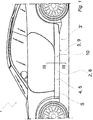
- the Fig. 1 shows a sill panel S in the installed state on a motor vehicle 1 with an upper portion 2 and a lower portion 3, wherein a portion of the outer side 4 of the upper portion 2 forms a viewing area 5 of the sill panel S, which is visible in the Verbauschreib the sill panel S on the motor vehicle 1 , wherein the lower portion 3 releasably on a body member 6 (see. Fig. 3a to Fig. 3f ) of the motor vehicle 1 can be fixed and extends to a transition section 7, wherein the lower region 3 forms the not visible in VerbauSullivan area 3 'of the sill panel S (therefore, only its location indicated by an arrow here).
- the Fig. 2 shows a three-dimensional view of the sill panel S according to Fig. 1 for a motor vehicle 1 with an upper area 2 and a lower area 3, wherein a part of the outer side 4 of the upper area 2 forms a viewing area 5 of the sill panel S, which is visible in the Verbauschreib the sill panel S on the motor vehicle 1, the lower portion. 3 detachably on a body element 6 (see. Fig. 3a to Fig. 3f ) of the motor vehicle 1 can be fixed and extends up to a transition section 7, wherein the lower region 3 forms the not visible in VerbauSullivan area 3 'of the sill panel S.
- the sill panel S is formed of at least two parts 8, 9, wherein the upper portion 2 forming the visible part 8 consists of a thermoplastic material X and on the outside 4 at least one lacquer layer 10 and, wherein a lower portion 3 forming functional part 9 of a further thermoplastic material Y and is unpainted and, wherein the visible part 8 is connected to the functional part 9 in the region of the transition section 7.
- the visible part 8 can with the functional part 9 via at least one latching connection 11 a, 11 b, 11 c, 11 d and / or at least one welded joining zone 20 and / or at least one adhesive layer 30, which are described in the following Fig. 3a to Fig. 3f are shown.
- FIG. 3a to Fig. 3d show different embodiments of at least one locking connection 11a, 11b, 11c, 11d which connect the visible part 8 with the functional part 9.
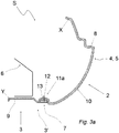
- Fig. 3a is from the transition section 7 of the functional part 9, a latching hook 12 at an angle.
- the latching hook 12 is received in an integrally formed with the visible part 8 locking hook receptacle 13.
- Latch hook 12 and latch hook receptacle 13 thereby form the latching connection 11 a.
- the edge region of the flat transition section 7 of the functional part 9 has a latching hook 12.
- the latching hook 12 is received in an integrally formed with the visible part 8 locking hook receptacle 13.
- Latch hook 12 and latch hook receptacle 13 thereby form the latching connection 11b.
- the edge region of the flat transition section 7 of the functional part 9 has a catch hook receptacle 13.
- the latching hook receptacle 13 accommodates a latching hook 12 formed in one piece with the viewing part 8. Detent hook 12 and latch hook receptacle 13 thereby form the latching connection 11 c.
- the edge region of the flat transition section 7 of the functional part 9 has a variant of a latching hook receptacle 13.
- the latching hook receptacle 13 accommodates a latching hook 12 formed in one piece with the viewing part 8.
- Latch hook 12 and latch hook receptacle 13 thereby form the latching connection 11d.
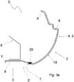
- the visible part 8 is connected to the functional part 9 via at least one welded joining zone 20.
- the joining zone 20 may be formed in particular by a laser welding method or an ultrasonic welding method.
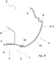
- the visible part 8 is connected to the functional part 9 via at least one adhesive layer 30.
Landscapes
- Engineering & Computer Science (AREA)
- Mechanical Engineering (AREA)
- Body Structure For Vehicles (AREA)
- Compositions Of Macromolecular Compounds (AREA)
Abstract
Description
- Die vorliegende Erfindung betrifft eine Schwellerverkleidung für ein Kraftfahrzeug mit einem oberen Bereich und einem unteren Bereich, wobei ein Teil der Außenseite des oberen Bereichs einen Sichtbereich der Schwellerverkleidung bildet, der im Verbauzustand der Schwellerverkleidung am Kraftfahrzeug sichtbar ist, wobei der untere Bereich lösbar an einem Karosserieelement des Kraftfahrzeuges festlegbar ist und sich bis zu einem Übergangsabschnitt erstreckt, wobei der untere Bereich den im Verbauzustand nicht sichtbaren Bereich der Schwellerverkleidung ausbildet.
- Eine gattungsgemäße Schwellerverkleidung kann der Patentschrift
EP 1 591 319 B1 entnommen werden. Nachteilig an einer Schwellerverkleidung gemäß dem Stand der Technik ist die Tatsache, dass aufgrund der großen Baulänge - in der Regel deutlich über einen Meter - von Schwellerverkleidungen die hiermit verbundene thermische Längenausdehnung durch die Wahl eines mit Füllstoffen verstärkten thermoplastischen Werkstoffes für die Schwellerverkleidung teilweise kompensiert werden muss. Ansonsten kommt es zu einem Ausbeulen der Schwellerverkleidung am Kraftfahrzeug. Für eine noch ausreichende Oberflächenqualität der Schwellerverkleidung kann insbesondere aufgrund der Füllstoffe nur sogenanntes 1 A-Material verwendet werden. Die Herstellung der Schwellerverkleidung mit Rücklaufmaterial oder Rezyklat ist aufgrund der sich einstellenden deutlich schlechteren Oberflächenqualität nicht möglich, da insbesondere eine im Sichtbereich aufgebrachte Lackschicht dann zu einem unakzeptablen Erscheinungsbild führt. - Aufgabe der vorliegenden Erfindung ist es daher, eine Schwellerverkleidung anzugeben, die weiterhin eine akzeptable Längenausdehnung und Oberflächenqualität aufweist und gleichzeitig mit einem kostengünstigeren Material herstellbar ist.
- Diese Aufgabe wird vorliegend erfüllt durch eine Schwellerverkleidung für ein Kraftfahrzeug mit einem oberen Bereich und einem unteren Bereich, wobei ein Teil der Außenseite des oberen Bereichs einen Sichtbereich der Schwellerverkleidung bildet, der im Verbauzustand der Schwellerverkleidung am Kraftfahrzeug sichtbar ist, wobei der untere Bereich lösbar an einem Karosserieelement des Kraftfahrzeuges festlegbar ist und sich bis zu einem Übergangsabschnitt erstreckt, wobei der untere Bereich den im Verbauzustand nicht sichtbaren Bereich der Schwellerverkleidung ausbildet, wobei die Schwellerverkleidung aus wenigstens zwei Teilen ausgebildet ist, wobei ein den oberen Bereich bildendes Sichtteil aus einem thermoplastischen Werkstoff besteht und auf der Außenseite wenigstens eine Lackschicht aufweist und, wobei ein den unteren Bereich bildendes Funktionsteil aus einem weiteren thermoplastischen Werkstoff besteht und unlackiert ist und, wobei das Sichtteil mit dem Funktionsteil im Bereich des Übergangsabschnittes verbunden ist. Erfindungsgemäß erlaubt es die Trennung der Schwellerverkleidung in einen Funktionsteil und in einen Sichtteil die für die beiden Teile verwendeten thermoplastischen Werkstoffe unterschiedlich zu wählen. Der Werkstoff des Funktionsteil muss dann nicht mehr die hohe Oberflächenqualität des Sichtteils aufweisen bzw. gewährleisten können und kann entsprechend eine geringere Qualität und somit einen geringeren Materialpreis aufweisen. Ein weiterer Vorteil besteht darin, dass das Funktionsteil nicht lackiert werden muss und somit entsprechend Lack und Lackierzeit eingespart werden kann.
- Das Sichtteil kann mit dem Funktionsteil über wenigstens eine Rastverbindung und/oder wenigstens eine geschweißte Fügezone und/oder wenigstens eine Klebstoffschicht verbunden sein.
- Der thermoplastische Werkstoff und/oder der weitere thermoplastische Werkstoff kann/können Füllstoffe umfassen. Insbesondere können der thermoplastische Werkstoff und der weitere thermoplastische Werkstoff Füllstoffe umfassen, wobei der weitere thermoplastische Werkstoff einen höheren Gehalt an Füllstoffen als der thermoplastische Werkstoff aufweist. Der Gehalt an Füllstoffen in dem weiteren thermoplastischen Werkstoff des Funktionsteils kann hierdurch gegenüber dem Gehalt an Füllstoffen in einem Material einer Schwellerverkleidung des Standes der Technik weiter erhöht, und somit die thermische Längenausdehnung weiter verringert werden, da hiermit einhergehende Beeinträchtigungen der Oberflächenqualität für das Funktionsteil unerheblich sind, da dieses insbesondere unlackiert ist.
- Die Füllstoffe können Kreide, Sand, Kieselgur, Glasfasern, Kohlefasern, Flachsfasern, Jutefasern, Borfasern, Aramidfasern, Glaskugeln, Zinkoxid, Quarz, Holzmehl, Stärke, Graphit, Ruß und/oder Talkum oder Kombinationen der vorgenannten Füllstoffe umfassen. Besonders bevorzugt umfassen die Füllstoffe des thermoplastischen Werkstoffes und/oder des weiteren thermoplastischen Werkstoffes Talkum und/oder Glasfasern. Der Gehalt des Füllstoffes des thermoplastischen Werkstoffes und/oder des weiteren thermoplastischen Werkstoffes kann zwischen 15 wt.% bis 40 wt.%, bevorzugt zwischen 20 wt.% bis 30 wt.% betragen (wt.% entspricht Gewichtsprozent).
- Der thermoplastische Werkstoff und/oder der weitere thermoplastische Werkstoff kann/können ein Polyolefin und/oder ein thermoplastisches Elastomere (kurz TPE), insbesondere ein thermoplastisches Elastomere auf Olefinbasis (kurz TPE-O oder TPE-V) umfassen. Besonders bevorzugt umfasst der thermoplastische Werkstoff und/oder der weitere thermoplastische Werkstoff einen Blend aus Polypropylen/Ethylen-Propylen-DienKautschuk (kurz PP/EPDM).
- Das Funktionsteil kann aus einem geschäumten thermoplastischen Werkstoff bestehen. Aufgrund dessen, dass die Oberflächenqualität der Schwellerverkleidung durch den thermoplastischen Werkstoff des Sichtteils definiert ist, kann der weitere thermoplastische Werkstoff des Funktionsteils sogar aus einem, vorzugsweise chemisch und/oder physikalisch, geschäumten thermoplastischen Werkstoff bestehen. Hierdurch lässt sich zusätzlich zu den bereits beschriebenen Vorteilen das Gewicht der Schwellerverkleidung reduzieren und weiter Kosten für den weiteren thermoplastischen Werkstoff einsparen.
- Der weitere thermoplastische Werkstoff des Funktionsteils kann Rücklaufmaterial und/oder ein Rezyklat umfassen. Üblicherweise weisen Rücklaufmaterial oder Rezyklat eine unzureichende Oberflächenqualität auf, können bei der erfindungsgemäßen Schwellerverkleidung jedoch trotzdem für das Funktionsteil eingesetzt werden, da allein das Sichtteil die Oberflächenqualität definiert.
- Die Teile der Schwellerverkleidung können in einem Spritzgußverfahren hergestellt sein.
- Teil der Erfindung ist ferner ein Kraftfahrzeug mit einer vorstehend beschriebenen Schwellerverkleidung, oder mit einer Schwellerverkleidung nach einem der Ansprüche 1 bis 9.
- Die Erfindung wird anhand der nachfolgenden lediglich Ausführungsbeispiele darstellender Figuren näher erläutert. Gleiche oder funktionsgleiche Elemente sind mit den gleichen Bezugszeichen versehen. Es zeigen:
- Fig. 1
- Eine Schwellerverkleidung im Verbauzustand an einem Kraftfahrzeug;
- Fig. 2
- eine dreidimensionale Ansicht der Schwellerverkleidung gemäß
Fig. 1 ; - Fig. 3a-3f
- Querschnittsdarstellungen von Varianten einer Schwellerverkleidung gemäß der Schnittlinie III-III aus
Fig. 1 . - Die
Fig. 1 zeigt eine Schwellerverkleidung S im Verbauzustand an einem Kraftfahrzeug 1 mit einem oberen Bereich 2 und einem unteren Bereich 3, wobei ein Teil der Außenseite 4 des oberen Bereichs 2 einen Sichtbereich 5 der Schwellerverkleidung S bildet, der im Verbauzustand der Schwellerverkleidung S am Kraftfahrzeug 1 sichtbar ist, wobei der untere Bereich 3 lösbar an einem Karosserieelement 6 (vgl.Fig. 3a bis Fig. 3f ) des Kraftfahrzeuges 1 festlegbar ist und sich bis zu einem Übergangsabschnitt 7 erstreckt, wobei der untere Bereich 3 den im Verbauzustand nicht sichtbaren Bereich 3' der Schwellerverkleidung S ausbildet (daher ist hier nur dessen Lage mit einem Pfeil angedeutet). - Die
Fig. 2 zeigt eine dreidimensionale Ansicht der Schwellerverkleidung S gemäßFig. 1 für ein Kraftfahrzeug 1 mit einem oberen Bereich 2 und einem unteren Bereich 3, wobei ein Teil der Außenseite 4 des oberen Bereichs 2 einen Sichtbereich 5 der Schwellerverkleidung S bildet, der im Verbauzustand der Schwellerverkleidung S am Kraftfahrzeug 1 sichtbar ist, wobei der untere Bereich 3 lösbar an einem Karosserieelement 6 (vgl.Fig. 3a bis Fig. 3f ) des Kraftfahrzeuges 1 festlegbar ist und sich bis zu einem Übergangsabschnitt 7 erstreckt, wobei der untere Bereich 3 den im Verbauzustand nicht sichtbaren Bereich 3' der Schwellerverkleidung S ausbildet. Die Schwellerverkleidung S ist aus wenigstens zwei Teilen 8, 9 ausgebildet, wobei ein den oberen Bereich 2 bildendes Sichtteil 8 aus einem thermoplastischen Werkstoff X besteht und auf der Außenseite 4 wenigstens eine Lackschicht 10 aufweist und, wobei ein den unteren Bereich 3 bildendes Funktionsteil 9 aus einem weiteren thermoplastischen Werkstoff Y besteht und unlackiert ist und, wobei das Sichtteil 8 mit dem Funktionsteil 9 im Bereich des Übergangsabschnittes 7 verbunden ist. Das Sichtteil 8 kann mit dem Funktionsteil 9 über wenigstens eine Rastverbindung 11 a, 11 b, 11 c, 11 d und/oder wenigstens eine geschweißte Fügezone 20 und/oder wenigstens eine Klebstoffschicht 30 verbunden sein, die in den folgendenFig. 3a bis Fig. 3f dargestellt sind. - Die Querschnittsdarstellungen in
Fig. 3a bis Fig. 3d gemäß der Schnittlinie III-III ausFig. 1 , zeigen unterschiedliche Ausbildungen der wenigstens einen Rastverbindung 11a, 11 b, 11 c, 11d die das Sichtteil 8 mit dem Funktionsteil 9 verbinden. - In
Fig. 3a steht von dem Übergangsabschnitt 7 des Funktionsteils 9 ein Rasthaken 12 in einem Winkel ab. Der Rasthaken 12 ist in einer einstückig mit dem Sichtteil 8 ausgebildeten Rasthakenaufnahme 13 aufgenommen. Rasthaken 12 und Rasthakenaufnahme 13 bilden hierdurch die Rastverbindung 11 a aus. - In
Fig. 3b weist der Randbereich des flach ausgebildeten Übergangsabschnitts 7 des Funktionsteils 9 einen Rasthaken 12 auf. Der Rasthaken 12 ist in einer einstückig mit dem Sichtteil 8 ausgebildeten Rasthakenaufnahme 13 aufgenommen. Rasthaken 12 und Rasthakenaufnahme 13 bilden hierdurch die Rastverbindung 11b aus. - In
Fig. 3c weist der Randbereich des flach ausgebildeten Übergangsabschnitts 7 des Funktionsteils 9 eine Rasthakenaufnahme 13 auf. Die Rasthakenaufnahme 13 nimmt einen einstückig mit dem Sichtteil 8 ausgebildeten Rasthaken 12 auf. Rasthaken 12 und Rasthakenaufnahme 13 bilden hierdurch die Rastverbindung 11 c aus. - In
Fig. 3d weist der Randbereich des flach ausgebildeten Übergangsabschnitts 7 des Funktionsteils 9 eine Variante einer Rasthakenaufnahme 13 auf. Die Rasthakenaufnahme 13 nimmt einen einstückig mit dem Sichtteil 8 ausgebildeten Rasthaken 12 auf. Rasthaken 12 und Rasthakenaufnahme 13 bilden hierdurch die Rastverbindung 11d aus. - Die Querschnittsdarstellungen in
Fig. 3e undFig. 3f gemäß der Schnittlinie III-III ausFig. 1 , zeigen weitere Ausbildungen der Verbindungszone zwischen Sichtteil 8 und Funktionsteil 9. - In
Fig. 3e ist das Sichtteil 8 mit dem Funktionsteil 9 über wenigstens eine geschweißte Fügezone 20 verbunden. Die Fügezone 20 kann insbesondere durch ein Laserschweißverfahren oder ein Ultraschallschweißverfahren ausgebildet sein. - In
Fig. 3f ist das Sichtteil 8 mit dem Funktionsteil 9 über wenigstens eine Klebstoffschicht 30 verbunden. - Nachfolgendes gilt generell für alle in den vorstehend beschriebenen
Fig. 1 bis Fig. 3f dargestellten Schwellerverkleidungen: - Der thermoplastische Werkstoff X und/oder der weitere thermoplastische Werkstoff Y kann/können Füllstoffe umfassen. Insbesondere können der thermoplastische Werkstoff X und der weitere thermoplastische Werkstoff Y Füllstoffe umfassen, wobei der weitere thermoplastische Werkstoff Y einen höheren Gehalt an Füllstoffen als der thermoplastische Werkstoff X aufweist. Die Füllstoffe können Kreide, Sand, Kieselgur, Glasfasern, Kohlefasern, Flachsfasern, Jutefasern, Borfasern, Aramidfasern, Glaskugeln, Zinkoxid, Quarz, Holzmehl, Stärke, Graphit, Ruß und/oder Talkum oder Kombinationen der vorgenannten Füllstoffe umfassen. Der thermoplastische Werkstoff X und/oder der weitere thermoplastische Werkstoff Y kann/können ein Polyolefin (PP, PE) und/oder ein thermoplastisches Elastomere (TPE), insbesondere ein thermoplastisches Elastomere auf Olefinbasis (TPE-O, TPE-V) umfassen. Besonders bevorzugt umfasst der thermoplastische Werkstoff X und/oder der weitere thermoplastische Werkstoff Y einen Blend aus Polypropylen/Ethylen-Propylen-Dien-Kautschuk (kurz PP/EPDM). Das Funktionsteil 9 kann aus einem geschäumten thermoplastischen Werkstoff Y bestehen. Der thermoplastische Werkstoff Y des Funktionsteils 9 kann Rücklaufmaterial und/oder ein Rezyklat umfassen. Die Teile 8, 9 der Schwellerverkleidung S können in einem Spritzgußverfahren hergestellt sein.
Claims (10)
- Schwellerverkleidung (S) für ein Kraftfahrzeug (1) mit- einem oberen Bereich (2) und- einem unteren Bereich (3),wobei ein Teil der Außenseite (4) des oberen Bereichs (2) einen Sichtbereich (5) der Schwellerverkleidung (S) bildet, der im Verbauzustand der Schwellerverkleidung (S) am Kraftfahrzeug (1) sichtbar ist,
wobei der untere Bereich (3) lösbar an einem Karosserieelement (6) des Kraftfahrzeuges (1) festlegbar ist und sich bis zu einem Übergangsabschnitt (7) erstreckt, wobei der untere Bereich (3) den im Verbauzustand nicht sichtbaren Bereich (3') der Schwellerverkleidung (S) ausbildet,
dadurch gekennzeichnet, dass
die Schwellerverkleidung (S) aus wenigstens zwei Teilen (8, 9) ausgebildet ist, wobei ein den oberen Bereich (2) bildendes Sichtteil (8) aus einem thermoplastischen Werkstoff (X) besteht und auf der Außenseite (4) wenigstens eine Lackschicht (10) aufweist und,
wobei ein den unteren Bereich (3) bildendes Funktionsteil (9) aus einem weiteren thermoplastischen Werkstoff (Y) besteht und unlackiert ist und,
wobei das Sichtteil (8) mit dem Funktionsteil (9) im Bereich des Übergangsabschnittes (7) verbunden ist. - Schwellerverkleidung (S) nach Anspruch 1, dadurch gekennzeichnet, dass das Sichtteil (8) mit dem Funktionsteil (9) über wenigstens eine Rastverbindung (11a, 11 b, 11 c, 11 d) und/oder wenigstens eine geschweißte Fügezone (20) und/oder wenigstens eine Klebstoffschicht (30) verbunden ist.
- Schwellerverkleidung (S) nach einem der vorstehenden Ansprüche, dadurch gekennzeichnet, dass das der thermoplastische Werkstoff (X) und/oder der weitere thermoplastische Werkstoff (Y) Füllstoffe umfasst/umfassen.
- Schwellerverkleidung (S) nach einem der vorstehenden Ansprüche, dadurch gekennzeichnet, dass der thermoplastische Werkstoff (X) und der weitere thermoplastische Werkstoff (Y) Füllstoffe umfassen, wobei der weitere thermoplastische Werkstoff (Y) einen höheren Gehalt an Füllstoffen als der thermoplastische Werkstoff (X) aufweist.
- Schwellerverkleidung (S) nach einem der vorstehenden Ansprüche 3 oder 4, dadurch gekennzeichnet, dass die Füllstoffe Kreide, Sand, Kieselgur, Glasfasern, Kohlefasern, Flachsfasern, Jutefasern, Borfasern, Aramidfasern, Glaskugeln, Zinkoxid, Quarz, Holzmehl, Stärke, Graphit, Ruß und/oder Talkum oder Kombinationen der vorgenannten Füllstoffe umfassen.
- Schwellerverkleidung (S) nach einem der vorstehenden Ansprüche, dadurch gekennzeichnet, dass der thermoplastische Werkstoff (X) und/oder der weitere thermoplastische Werkstoff (Y) ein Polyolefin (PP, PE) und/oder ein thermoplastisches Elastomere (TPE), insbesondere ein thermoplastisches Elastomere auf Olefinbasis (TPE-O, TPE-V) umfasst/umfassen.
- Schwellerverkleidung (S) nach einem der vorstehenden Ansprüche, dadurch gekennzeichnet, dass das Funktionsteil (9) aus einem geschäumten thermoplastischen Werkstoff (Y) besteht.
- Schwellerverkleidung (S) nach einem der vorstehenden Ansprüche, dadurch gekennzeichnet, dass der thermoplastische Werkstoff (Y) des Funktionsteils (9) Rücklaufmaterial und/oder ein Rezyklat umfasst.
- Schwellerverkleidung (S) nach einem der vorstehenden Ansprüche, dadurch gekennzeichnet, dass die Teile (8, 9) der Schwellerverkleidung (S) in einem Spritzgußverfahren hergestellt sind.
- Kraftfahrzeug mit einer Schwellerverkleidung (S) nach einem der vorstehenden Ansprüche.
Applications Claiming Priority (1)
| Application Number | Priority Date | Filing Date | Title |
|---|---|---|---|
| DE202015107057.8U DE202015107057U1 (de) | 2015-12-23 | 2015-12-23 | Schwellerverkleidung |
Publications (2)
| Publication Number | Publication Date |
|---|---|
| EP3184371A1 true EP3184371A1 (de) | 2017-06-28 |
| EP3184371B1 EP3184371B1 (de) | 2019-01-30 |
Family
ID=57539035
Family Applications (1)
| Application Number | Title | Priority Date | Filing Date |
|---|---|---|---|
| EP16202407.9A Not-in-force EP3184371B1 (de) | 2015-12-23 | 2016-12-06 | Schwellerverkleidung |
Country Status (2)
| Country | Link |
|---|---|
| EP (1) | EP3184371B1 (de) |
| DE (1) | DE202015107057U1 (de) |
Families Citing this family (1)
| Publication number | Priority date | Publication date | Assignee | Title |
|---|---|---|---|---|
| DE112019003650A5 (de) | 2018-07-20 | 2021-05-20 | Merck Patent Gmbh | Anzeigevorrichtung, deren Herstellung und Verwendung |
Citations (6)
| Publication number | Priority date | Publication date | Assignee | Title |
|---|---|---|---|---|
| GB2142594A (en) * | 1983-06-17 | 1985-01-23 | Honda Motor Co Ltd | Panel for automobile body |
| US20050093343A1 (en) * | 2003-10-15 | 2005-05-05 | Honda Motor Co., Ltd. | Installation structure for a side sill garnish |
| US20060145516A1 (en) * | 2002-09-27 | 2006-07-06 | Green Tokai Co., Ltd. | Clip house structure for mounting of automotive trim parts |
| EP1693252A1 (de) * | 2005-02-22 | 2006-08-23 | Peguform Gmbh | Befestigungsmechanismus |
| EP1591319B1 (de) | 2004-04-28 | 2009-04-15 | Dr. Ing. h.c. F. Porsche Aktiengesellschaft | Schwellerverkleidung für ein Fahrzeug |
| EP2525999A1 (de) * | 2010-01-18 | 2012-11-28 | Faurecia Exteriors GmbH | Befestigung einer längsträgerverkleidung an einem längsträger eines kraftfahrzeugs |
Family Cites Families (4)
| Publication number | Priority date | Publication date | Assignee | Title |
|---|---|---|---|---|
| DE3246767C2 (de) * | 1982-12-17 | 1984-09-27 | Daimler-Benz Ag, 7000 Stuttgart | Aerodynamische Verkleidung der seitlichen Längsträger für Personen- und Kombinationskraftwagen |
| DE19722551A1 (de) * | 1997-05-28 | 1998-12-03 | Hohe Gmbh & Co Kg | Verfahren zur Herstellung von Kunststoffteilen in einem Zwei-Komponenten-Spritzgußprozeß |
| JP5014951B2 (ja) * | 2007-10-31 | 2012-08-29 | 株式会社イノアックコーポレーション | 車両用サイドマッドガード |
| JP4688915B2 (ja) * | 2008-09-29 | 2011-05-25 | 株式会社ホンダアクセス | サイドアンダースポイラー取付構造 |
-
2015
- 2015-12-23 DE DE202015107057.8U patent/DE202015107057U1/de not_active Expired - Lifetime
-
2016
- 2016-12-06 EP EP16202407.9A patent/EP3184371B1/de not_active Not-in-force
Patent Citations (6)
| Publication number | Priority date | Publication date | Assignee | Title |
|---|---|---|---|---|
| GB2142594A (en) * | 1983-06-17 | 1985-01-23 | Honda Motor Co Ltd | Panel for automobile body |
| US20060145516A1 (en) * | 2002-09-27 | 2006-07-06 | Green Tokai Co., Ltd. | Clip house structure for mounting of automotive trim parts |
| US20050093343A1 (en) * | 2003-10-15 | 2005-05-05 | Honda Motor Co., Ltd. | Installation structure for a side sill garnish |
| EP1591319B1 (de) | 2004-04-28 | 2009-04-15 | Dr. Ing. h.c. F. Porsche Aktiengesellschaft | Schwellerverkleidung für ein Fahrzeug |
| EP1693252A1 (de) * | 2005-02-22 | 2006-08-23 | Peguform Gmbh | Befestigungsmechanismus |
| EP2525999A1 (de) * | 2010-01-18 | 2012-11-28 | Faurecia Exteriors GmbH | Befestigung einer längsträgerverkleidung an einem längsträger eines kraftfahrzeugs |
Also Published As
| Publication number | Publication date |
|---|---|
| DE202015107057U1 (de) | 2017-03-27 |
| EP3184371B1 (de) | 2019-01-30 |
Similar Documents
| Publication | Publication Date | Title |
|---|---|---|
| DE102014224400B4 (de) | Aufbaurahmen für Fahrzeug | |
| DE60036311T3 (de) | Verwendung von verglasung mit einem profiliertem band zu seiner installation in einer öffnung | |
| WO2010028901A1 (de) | Fussbodenpaneel mit einer trägerschicht aus kunststoff | |
| DE102012018752B4 (de) | Dichtungsstreifen | |
| DE19842456A1 (de) | Formgegenstände aus Kunstharz | |
| DE9306462U1 (de) | Heckfensterscheibe für Cabriolet-Fahrzeuge | |
| WO2004039619A1 (de) | Dichtungsstrang für karosseriedichtungen mit bereichsweise verstärktem dichtungsprofil | |
| DE102016125814A1 (de) | Zierteil | |
| EP1066167B1 (de) | Dichtungsprofil für kraftfahrzeuge | |
| DE102014105975A1 (de) | Kraftfahrzeug-Kunststoffkarosseriebeplankung | |
| DE69201035T2 (de) | Von Innenseite montierte Kraftfahrzeugverglasung. | |
| DE102011121720A1 (de) | Fensterglasführung | |
| DE102008056146A1 (de) | Verkleidung eines Unterbodens eines Personenkraftwagens | |
| WO2017157726A1 (de) | Profilleistenanordnung | |
| EP3768536A1 (de) | Fahrzeugdachdeckel mit einem rahmenteil | |
| EP3184371B1 (de) | Schwellerverkleidung | |
| DE102012023269A1 (de) | Außenspiegelanordnung für ein Kraftfahrzeug | |
| DE102016122947A1 (de) | Schwellerverkleidung | |
| DE102007044426B4 (de) | Vorrichtung zur Abdichtung eines Fensterschachts an einer Kraftfahrzeugtür | |
| DE9401563U1 (de) | Verstärktes Kunststoff-Formteil, insbesondere Kunststoffleiste für Kraftfahrzeuge | |
| DE102016002681B3 (de) | Dicht- und Blendleiste für die B-Säule eines Personenkraftwagens | |
| EP3181406B1 (de) | Verkleidungsteil für ein kraftfahrzeug, sowie verfahren zur herstellung eines verkleidungsteiles | |
| DE102009049455B4 (de) | Dichtungsprofil und Verfahren zur Herstellung eines Dichtungsprofils | |
| DE102018115241B4 (de) | Fahrzeug-PU-Composite-Bauteil mit einem eine Wabenstruktur aufweisenden Schichtaufbau und Verfahren zu dessen Herstellung | |
| DE102013003243A1 (de) | Fahrzeugtür |
Legal Events
| Date | Code | Title | Description |
|---|---|---|---|
| PUAI | Public reference made under article 153(3) epc to a published international application that has entered the european phase |
Free format text: ORIGINAL CODE: 0009012 |
|
| STAA | Information on the status of an ep patent application or granted ep patent |
Free format text: STATUS: THE APPLICATION HAS BEEN PUBLISHED |
|
| AK | Designated contracting states |
Kind code of ref document: A1 Designated state(s): AL AT BE BG CH CY CZ DE DK EE ES FI FR GB GR HR HU IE IS IT LI LT LU LV MC MK MT NL NO PL PT RO RS SE SI SK SM TR |
|
| AX | Request for extension of the european patent |
Extension state: BA ME |
|
| STAA | Information on the status of an ep patent application or granted ep patent |
Free format text: STATUS: REQUEST FOR EXAMINATION WAS MADE |
|
| 17P | Request for examination filed |
Effective date: 20171220 |
|
| RBV | Designated contracting states (corrected) |
Designated state(s): AL AT BE BG CH CY CZ DE DK EE ES FI FR GB GR HR HU IE IS IT LI LT LU LV MC MK MT NL NO PL PT RO RS SE SI SK SM TR |
|
| GRAP | Despatch of communication of intention to grant a patent |
Free format text: ORIGINAL CODE: EPIDOSNIGR1 |
|
| STAA | Information on the status of an ep patent application or granted ep patent |
Free format text: STATUS: GRANT OF PATENT IS INTENDED |
|
| INTG | Intention to grant announced |
Effective date: 20180730 |
|
| GRAS | Grant fee paid |
Free format text: ORIGINAL CODE: EPIDOSNIGR3 |
|
| GRAA | (expected) grant |
Free format text: ORIGINAL CODE: 0009210 |
|
| STAA | Information on the status of an ep patent application or granted ep patent |
Free format text: STATUS: THE PATENT HAS BEEN GRANTED |
|
| AK | Designated contracting states |
Kind code of ref document: B1 Designated state(s): AL AT BE BG CH CY CZ DE DK EE ES FI FR GB GR HR HU IE IS IT LI LT LU LV MC MK MT NL NO PL PT RO RS SE SI SK SM TR |
|
| REG | Reference to a national code |
Ref country code: GB Ref legal event code: FG4D Free format text: NOT ENGLISH |
|
| REG | Reference to a national code |
Ref country code: CH Ref legal event code: EP |
|
| REG | Reference to a national code |
Ref country code: AT Ref legal event code: REF Ref document number: 1092983 Country of ref document: AT Kind code of ref document: T Effective date: 20190215 |
|
| REG | Reference to a national code |
Ref country code: IE Ref legal event code: FG4D Free format text: LANGUAGE OF EP DOCUMENT: GERMAN |
|
| REG | Reference to a national code |
Ref country code: DE Ref legal event code: R096 Ref document number: 502016003271 Country of ref document: DE |
|
| REG | Reference to a national code |
Ref country code: LT Ref legal event code: MG4D |
|
| REG | Reference to a national code |
Ref country code: NL Ref legal event code: MP Effective date: 20190130 |
|
| PG25 | Lapsed in a contracting state [announced via postgrant information from national office to epo] |
Ref country code: PL Free format text: LAPSE BECAUSE OF FAILURE TO SUBMIT A TRANSLATION OF THE DESCRIPTION OR TO PAY THE FEE WITHIN THE PRESCRIBED TIME-LIMIT Effective date: 20190130 Ref country code: FI Free format text: LAPSE BECAUSE OF FAILURE TO SUBMIT A TRANSLATION OF THE DESCRIPTION OR TO PAY THE FEE WITHIN THE PRESCRIBED TIME-LIMIT Effective date: 20190130 Ref country code: LT Free format text: LAPSE BECAUSE OF FAILURE TO SUBMIT A TRANSLATION OF THE DESCRIPTION OR TO PAY THE FEE WITHIN THE PRESCRIBED TIME-LIMIT Effective date: 20190130 Ref country code: NL Free format text: LAPSE BECAUSE OF FAILURE TO SUBMIT A TRANSLATION OF THE DESCRIPTION OR TO PAY THE FEE WITHIN THE PRESCRIBED TIME-LIMIT Effective date: 20190130 Ref country code: ES Free format text: LAPSE BECAUSE OF FAILURE TO SUBMIT A TRANSLATION OF THE DESCRIPTION OR TO PAY THE FEE WITHIN THE PRESCRIBED TIME-LIMIT Effective date: 20190130 Ref country code: SE Free format text: LAPSE BECAUSE OF FAILURE TO SUBMIT A TRANSLATION OF THE DESCRIPTION OR TO PAY THE FEE WITHIN THE PRESCRIBED TIME-LIMIT Effective date: 20190130 Ref country code: PT Free format text: LAPSE BECAUSE OF FAILURE TO SUBMIT A TRANSLATION OF THE DESCRIPTION OR TO PAY THE FEE WITHIN THE PRESCRIBED TIME-LIMIT Effective date: 20190530 Ref country code: NO Free format text: LAPSE BECAUSE OF FAILURE TO SUBMIT A TRANSLATION OF THE DESCRIPTION OR TO PAY THE FEE WITHIN THE PRESCRIBED TIME-LIMIT Effective date: 20190430 |
|
| PG25 | Lapsed in a contracting state [announced via postgrant information from national office to epo] |
Ref country code: GR Free format text: LAPSE BECAUSE OF FAILURE TO SUBMIT A TRANSLATION OF THE DESCRIPTION OR TO PAY THE FEE WITHIN THE PRESCRIBED TIME-LIMIT Effective date: 20190501 Ref country code: HR Free format text: LAPSE BECAUSE OF FAILURE TO SUBMIT A TRANSLATION OF THE DESCRIPTION OR TO PAY THE FEE WITHIN THE PRESCRIBED TIME-LIMIT Effective date: 20190130 Ref country code: IS Free format text: LAPSE BECAUSE OF FAILURE TO SUBMIT A TRANSLATION OF THE DESCRIPTION OR TO PAY THE FEE WITHIN THE PRESCRIBED TIME-LIMIT Effective date: 20190530 Ref country code: LV Free format text: LAPSE BECAUSE OF FAILURE TO SUBMIT A TRANSLATION OF THE DESCRIPTION OR TO PAY THE FEE WITHIN THE PRESCRIBED TIME-LIMIT Effective date: 20190130 Ref country code: RS Free format text: LAPSE BECAUSE OF FAILURE TO SUBMIT A TRANSLATION OF THE DESCRIPTION OR TO PAY THE FEE WITHIN THE PRESCRIBED TIME-LIMIT Effective date: 20190130 Ref country code: BG Free format text: LAPSE BECAUSE OF FAILURE TO SUBMIT A TRANSLATION OF THE DESCRIPTION OR TO PAY THE FEE WITHIN THE PRESCRIBED TIME-LIMIT Effective date: 20190430 |
|
| PG25 | Lapsed in a contracting state [announced via postgrant information from national office to epo] |
Ref country code: AL Free format text: LAPSE BECAUSE OF FAILURE TO SUBMIT A TRANSLATION OF THE DESCRIPTION OR TO PAY THE FEE WITHIN THE PRESCRIBED TIME-LIMIT Effective date: 20190130 Ref country code: CZ Free format text: LAPSE BECAUSE OF FAILURE TO SUBMIT A TRANSLATION OF THE DESCRIPTION OR TO PAY THE FEE WITHIN THE PRESCRIBED TIME-LIMIT Effective date: 20190130 Ref country code: SK Free format text: LAPSE BECAUSE OF FAILURE TO SUBMIT A TRANSLATION OF THE DESCRIPTION OR TO PAY THE FEE WITHIN THE PRESCRIBED TIME-LIMIT Effective date: 20190130 Ref country code: RO Free format text: LAPSE BECAUSE OF FAILURE TO SUBMIT A TRANSLATION OF THE DESCRIPTION OR TO PAY THE FEE WITHIN THE PRESCRIBED TIME-LIMIT Effective date: 20190130 Ref country code: IT Free format text: LAPSE BECAUSE OF FAILURE TO SUBMIT A TRANSLATION OF THE DESCRIPTION OR TO PAY THE FEE WITHIN THE PRESCRIBED TIME-LIMIT Effective date: 20190130 Ref country code: EE Free format text: LAPSE BECAUSE OF FAILURE TO SUBMIT A TRANSLATION OF THE DESCRIPTION OR TO PAY THE FEE WITHIN THE PRESCRIBED TIME-LIMIT Effective date: 20190130 Ref country code: DK Free format text: LAPSE BECAUSE OF FAILURE TO SUBMIT A TRANSLATION OF THE DESCRIPTION OR TO PAY THE FEE WITHIN THE PRESCRIBED TIME-LIMIT Effective date: 20190130 |
|
| REG | Reference to a national code |
Ref country code: DE Ref legal event code: R097 Ref document number: 502016003271 Country of ref document: DE |
|
| PG25 | Lapsed in a contracting state [announced via postgrant information from national office to epo] |
Ref country code: SM Free format text: LAPSE BECAUSE OF FAILURE TO SUBMIT A TRANSLATION OF THE DESCRIPTION OR TO PAY THE FEE WITHIN THE PRESCRIBED TIME-LIMIT Effective date: 20190130 |
|
| PLBE | No opposition filed within time limit |
Free format text: ORIGINAL CODE: 0009261 |
|
| STAA | Information on the status of an ep patent application or granted ep patent |
Free format text: STATUS: NO OPPOSITION FILED WITHIN TIME LIMIT |
|
| 26N | No opposition filed |
Effective date: 20191031 |
|
| PG25 | Lapsed in a contracting state [announced via postgrant information from national office to epo] |
Ref country code: SI Free format text: LAPSE BECAUSE OF FAILURE TO SUBMIT A TRANSLATION OF THE DESCRIPTION OR TO PAY THE FEE WITHIN THE PRESCRIBED TIME-LIMIT Effective date: 20190130 |
|
| PG25 | Lapsed in a contracting state [announced via postgrant information from national office to epo] |
Ref country code: TR Free format text: LAPSE BECAUSE OF FAILURE TO SUBMIT A TRANSLATION OF THE DESCRIPTION OR TO PAY THE FEE WITHIN THE PRESCRIBED TIME-LIMIT Effective date: 20190130 |
|
| REG | Reference to a national code |
Ref country code: CH Ref legal event code: PL |
|
| REG | Reference to a national code |
Ref country code: BE Ref legal event code: MM Effective date: 20191231 |
|
| PG25 | Lapsed in a contracting state [announced via postgrant information from national office to epo] |
Ref country code: MC Free format text: LAPSE BECAUSE OF FAILURE TO SUBMIT A TRANSLATION OF THE DESCRIPTION OR TO PAY THE FEE WITHIN THE PRESCRIBED TIME-LIMIT Effective date: 20190130 |
|
| PG25 | Lapsed in a contracting state [announced via postgrant information from national office to epo] |
Ref country code: IE Free format text: LAPSE BECAUSE OF NON-PAYMENT OF DUE FEES Effective date: 20191206 Ref country code: LU Free format text: LAPSE BECAUSE OF NON-PAYMENT OF DUE FEES Effective date: 20191206 |
|
| PG25 | Lapsed in a contracting state [announced via postgrant information from national office to epo] |
Ref country code: LI Free format text: LAPSE BECAUSE OF NON-PAYMENT OF DUE FEES Effective date: 20191231 Ref country code: CH Free format text: LAPSE BECAUSE OF NON-PAYMENT OF DUE FEES Effective date: 20191231 Ref country code: BE Free format text: LAPSE BECAUSE OF NON-PAYMENT OF DUE FEES Effective date: 20191231 |
|
| PG25 | Lapsed in a contracting state [announced via postgrant information from national office to epo] |
Ref country code: CY Free format text: LAPSE BECAUSE OF FAILURE TO SUBMIT A TRANSLATION OF THE DESCRIPTION OR TO PAY THE FEE WITHIN THE PRESCRIBED TIME-LIMIT Effective date: 20190130 |
|
| PG25 | Lapsed in a contracting state [announced via postgrant information from national office to epo] |
Ref country code: HU Free format text: LAPSE BECAUSE OF FAILURE TO SUBMIT A TRANSLATION OF THE DESCRIPTION OR TO PAY THE FEE WITHIN THE PRESCRIBED TIME-LIMIT; INVALID AB INITIO Effective date: 20161206 Ref country code: MT Free format text: LAPSE BECAUSE OF FAILURE TO SUBMIT A TRANSLATION OF THE DESCRIPTION OR TO PAY THE FEE WITHIN THE PRESCRIBED TIME-LIMIT Effective date: 20190130 |
|
| GBPC | Gb: european patent ceased through non-payment of renewal fee |
Effective date: 20201206 |
|
| PG25 | Lapsed in a contracting state [announced via postgrant information from national office to epo] |
Ref country code: GB Free format text: LAPSE BECAUSE OF NON-PAYMENT OF DUE FEES Effective date: 20201206 |
|
| PGFP | Annual fee paid to national office [announced via postgrant information from national office to epo] |
Ref country code: FR Payment date: 20211130 Year of fee payment: 6 |
|
| REG | Reference to a national code |
Ref country code: DE Ref legal event code: R081 Ref document number: 502016003271 Country of ref document: DE Owner name: REHAU AUTOMOTIVE SE & CO. KG, DE Free format text: FORMER OWNER: REHAU AG + CO, 95111 REHAU, DE |
|
| PG25 | Lapsed in a contracting state [announced via postgrant information from national office to epo] |
Ref country code: MK Free format text: LAPSE BECAUSE OF FAILURE TO SUBMIT A TRANSLATION OF THE DESCRIPTION OR TO PAY THE FEE WITHIN THE PRESCRIBED TIME-LIMIT Effective date: 20190130 |
|
| PGFP | Annual fee paid to national office [announced via postgrant information from national office to epo] |
Ref country code: DE Payment date: 20220608 Year of fee payment: 7 |
|
| REG | Reference to a national code |
Ref country code: AT Ref legal event code: MM01 Ref document number: 1092983 Country of ref document: AT Kind code of ref document: T Effective date: 20211206 |
|
| PG25 | Lapsed in a contracting state [announced via postgrant information from national office to epo] |
Ref country code: AT Free format text: LAPSE BECAUSE OF NON-PAYMENT OF DUE FEES Effective date: 20211206 |
|
| PG25 | Lapsed in a contracting state [announced via postgrant information from national office to epo] |
Ref country code: FR Free format text: LAPSE BECAUSE OF NON-PAYMENT OF DUE FEES Effective date: 20221231 |
|
| REG | Reference to a national code |
Ref country code: DE Ref legal event code: R119 Ref document number: 502016003271 Country of ref document: DE |
|
| PG25 | Lapsed in a contracting state [announced via postgrant information from national office to epo] |
Ref country code: DE Free format text: LAPSE BECAUSE OF NON-PAYMENT OF DUE FEES Effective date: 20240702 |
|
| PG25 | Lapsed in a contracting state [announced via postgrant information from national office to epo] |
Ref country code: DE Free format text: LAPSE BECAUSE OF NON-PAYMENT OF DUE FEES Effective date: 20240702 |