EP3184310A1 - Liquid container member - Google Patents
Liquid container member Download PDFInfo
- Publication number
- EP3184310A1 EP3184310A1 EP16205008.2A EP16205008A EP3184310A1 EP 3184310 A1 EP3184310 A1 EP 3184310A1 EP 16205008 A EP16205008 A EP 16205008A EP 3184310 A1 EP3184310 A1 EP 3184310A1
- Authority
- EP
- European Patent Office
- Prior art keywords
- liquid
- liquid containing
- channel
- tube
- ink
- Prior art date
- Legal status (The legal status is an assumption and is not a legal conclusion. Google has not performed a legal analysis and makes no representation as to the accuracy of the status listed.)
- Granted
Links
Images





Classifications
-
- B—PERFORMING OPERATIONS; TRANSPORTING
- B41—PRINTING; LINING MACHINES; TYPEWRITERS; STAMPS
- B41J—TYPEWRITERS; SELECTIVE PRINTING MECHANISMS, i.e. MECHANISMS PRINTING OTHERWISE THAN FROM A FORME; CORRECTION OF TYPOGRAPHICAL ERRORS
- B41J2/00—Typewriters or selective printing mechanisms characterised by the printing or marking process for which they are designed
- B41J2/005—Typewriters or selective printing mechanisms characterised by the printing or marking process for which they are designed characterised by bringing liquid or particles selectively into contact with a printing material
- B41J2/01—Ink jet
- B41J2/17—Ink jet characterised by ink handling
- B41J2/175—Ink supply systems ; Circuit parts therefor
- B41J2/17503—Ink cartridges
- B41J2/17506—Refilling of the cartridge
-
- B—PERFORMING OPERATIONS; TRANSPORTING
- B41—PRINTING; LINING MACHINES; TYPEWRITERS; STAMPS
- B41J—TYPEWRITERS; SELECTIVE PRINTING MECHANISMS, i.e. MECHANISMS PRINTING OTHERWISE THAN FROM A FORME; CORRECTION OF TYPOGRAPHICAL ERRORS
- B41J2/00—Typewriters or selective printing mechanisms characterised by the printing or marking process for which they are designed
- B41J2/005—Typewriters or selective printing mechanisms characterised by the printing or marking process for which they are designed characterised by bringing liquid or particles selectively into contact with a printing material
- B41J2/01—Ink jet
- B41J2/17—Ink jet characterised by ink handling
- B41J2/175—Ink supply systems ; Circuit parts therefor
- B41J2/17503—Ink cartridges
- B41J2/17513—Inner structure
-
- B—PERFORMING OPERATIONS; TRANSPORTING
- B41—PRINTING; LINING MACHINES; TYPEWRITERS; STAMPS
- B41J—TYPEWRITERS; SELECTIVE PRINTING MECHANISMS, i.e. MECHANISMS PRINTING OTHERWISE THAN FROM A FORME; CORRECTION OF TYPOGRAPHICAL ERRORS
- B41J2/00—Typewriters or selective printing mechanisms characterised by the printing or marking process for which they are designed
- B41J2/005—Typewriters or selective printing mechanisms characterised by the printing or marking process for which they are designed characterised by bringing liquid or particles selectively into contact with a printing material
- B41J2/01—Ink jet
- B41J2/17—Ink jet characterised by ink handling
- B41J2/175—Ink supply systems ; Circuit parts therefor
- B41J2/17503—Ink cartridges
- B41J2/17553—Outer structure
-
- B—PERFORMING OPERATIONS; TRANSPORTING
- B41—PRINTING; LINING MACHINES; TYPEWRITERS; STAMPS
- B41J—TYPEWRITERS; SELECTIVE PRINTING MECHANISMS, i.e. MECHANISMS PRINTING OTHERWISE THAN FROM A FORME; CORRECTION OF TYPOGRAPHICAL ERRORS
- B41J2/00—Typewriters or selective printing mechanisms characterised by the printing or marking process for which they are designed
- B41J2/005—Typewriters or selective printing mechanisms characterised by the printing or marking process for which they are designed characterised by bringing liquid or particles selectively into contact with a printing material
- B41J2/01—Ink jet
- B41J2/135—Nozzles
- B41J2/14—Structure thereof only for on-demand ink jet heads
- B41J2/14016—Structure of bubble jet print heads
- B41J2/14032—Structure of the pressure chamber
- B41J2/1404—Geometrical characteristics
-
- B—PERFORMING OPERATIONS; TRANSPORTING
- B41—PRINTING; LINING MACHINES; TYPEWRITERS; STAMPS
- B41J—TYPEWRITERS; SELECTIVE PRINTING MECHANISMS, i.e. MECHANISMS PRINTING OTHERWISE THAN FROM A FORME; CORRECTION OF TYPOGRAPHICAL ERRORS
- B41J2/00—Typewriters or selective printing mechanisms characterised by the printing or marking process for which they are designed
- B41J2/005—Typewriters or selective printing mechanisms characterised by the printing or marking process for which they are designed characterised by bringing liquid or particles selectively into contact with a printing material
- B41J2/01—Ink jet
- B41J2/135—Nozzles
- B41J2/14—Structure thereof only for on-demand ink jet heads
- B41J2/14016—Structure of bubble jet print heads
- B41J2/14072—Electrical connections, e.g. details on electrodes, connecting the chip to the outside...
-
- B—PERFORMING OPERATIONS; TRANSPORTING
- B41—PRINTING; LINING MACHINES; TYPEWRITERS; STAMPS
- B41J—TYPEWRITERS; SELECTIVE PRINTING MECHANISMS, i.e. MECHANISMS PRINTING OTHERWISE THAN FROM A FORME; CORRECTION OF TYPOGRAPHICAL ERRORS
- B41J2/00—Typewriters or selective printing mechanisms characterised by the printing or marking process for which they are designed
- B41J2/005—Typewriters or selective printing mechanisms characterised by the printing or marking process for which they are designed characterised by bringing liquid or particles selectively into contact with a printing material
- B41J2/01—Ink jet
- B41J2/135—Nozzles
- B41J2/14—Structure thereof only for on-demand ink jet heads
- B41J2/14016—Structure of bubble jet print heads
- B41J2/14088—Structure of heating means
- B41J2/14112—Resistive element
-
- B—PERFORMING OPERATIONS; TRANSPORTING
- B41—PRINTING; LINING MACHINES; TYPEWRITERS; STAMPS
- B41J—TYPEWRITERS; SELECTIVE PRINTING MECHANISMS, i.e. MECHANISMS PRINTING OTHERWISE THAN FROM A FORME; CORRECTION OF TYPOGRAPHICAL ERRORS
- B41J2/00—Typewriters or selective printing mechanisms characterised by the printing or marking process for which they are designed
- B41J2/005—Typewriters or selective printing mechanisms characterised by the printing or marking process for which they are designed characterised by bringing liquid or particles selectively into contact with a printing material
- B41J2/01—Ink jet
- B41J2/135—Nozzles
- B41J2/14—Structure thereof only for on-demand ink jet heads
- B41J2/14016—Structure of bubble jet print heads
- B41J2/14088—Structure of heating means
- B41J2/14112—Resistive element
- B41J2/14129—Layer structure
-
- B—PERFORMING OPERATIONS; TRANSPORTING
- B41—PRINTING; LINING MACHINES; TYPEWRITERS; STAMPS
- B41J—TYPEWRITERS; SELECTIVE PRINTING MECHANISMS, i.e. MECHANISMS PRINTING OTHERWISE THAN FROM A FORME; CORRECTION OF TYPOGRAPHICAL ERRORS
- B41J2/00—Typewriters or selective printing mechanisms characterised by the printing or marking process for which they are designed
- B41J2/005—Typewriters or selective printing mechanisms characterised by the printing or marking process for which they are designed characterised by bringing liquid or particles selectively into contact with a printing material
- B41J2/01—Ink jet
- B41J2/135—Nozzles
- B41J2/14—Structure thereof only for on-demand ink jet heads
- B41J2/14016—Structure of bubble jet print heads
- B41J2/14145—Structure of the manifold
-
- B—PERFORMING OPERATIONS; TRANSPORTING
- B41—PRINTING; LINING MACHINES; TYPEWRITERS; STAMPS
- B41J—TYPEWRITERS; SELECTIVE PRINTING MECHANISMS, i.e. MECHANISMS PRINTING OTHERWISE THAN FROM A FORME; CORRECTION OF TYPOGRAPHICAL ERRORS
- B41J2/00—Typewriters or selective printing mechanisms characterised by the printing or marking process for which they are designed
- B41J2/005—Typewriters or selective printing mechanisms characterised by the printing or marking process for which they are designed characterised by bringing liquid or particles selectively into contact with a printing material
- B41J2/01—Ink jet
- B41J2/17—Ink jet characterised by ink handling
- B41J2/175—Ink supply systems ; Circuit parts therefor
- B41J2/17503—Ink cartridges
- B41J2/17513—Inner structure
- B41J2002/17516—Inner structure comprising a collapsible ink holder, e.g. a flexible bag
Definitions
- the present invention relates to a liquid containing member that can contain a liquid having a precipitating component.
- Inkjet printers have been known as an example of a liquid consuming apparatus that consumes a liquid (e.g., ink) having a precipitating component (e.g., pigment) by ejecting it from a liquid ejecting portion that can eject a liquid.
- a liquid containing member e.g., ink cartridge
- a liquid containing portion e.g., ink pack (liquid bag)
- a liquid is supplied from the liquid containing member contained inside the casing to the liquid ejecting portion.
- This liquid containing member is provided with a liquid supply port through which a liquid contained in the liquid containing portion is supplied to the liquid ejecting portion.
- the liquid supplied from the liquid supply port to the liquid ejecting portion has to be controlled such that a change in the concentration of the precipitating component is suppressed.
- the reason for this is that, if the concentration of the precipitating component in the liquid supplied from the liquid supply port is non-uniform, a liquid having a uniform concentration may not be ejected from the liquid ejecting portion. In this case, for example, when ejecting the liquid from the liquid ejecting portion onto paper and printing an image or the like thereon, the density of the printed image changes, resulting in a deterioration in the printing quality.
- a liquid supply port (liquid discharge portion) is disposed at the center in the vertical direction of a liquid containing portion (ink pack), and liquid sucking portions (liquid sucking channels) that can suck a liquid (ink) are provided respectively at an upper portion on the anti-gravity direction side and a lower portion on the gravity direction side of the liquid supply port. If a liquid having a high concentration of the precipitating component and a liquid having a low concentration of the precipitating component are respectively sucked by the provided liquid sucking portions and mixed thereby, a liquid (ink) having a uniform concentration of the precipitating component is discharged from the liquid containing member (see JP-A-2008-87486 , for example).
- both the two liquid sucking portions provided at the upper and lower portions are positioned at the center in the vertical direction of the liquid containing portion, and thus, in the liquid containing portion, a liquid in the vicinity of the center near the liquid sucking portions is easily sucked out, whereas a liquid at the lower end on the gravity direction side or at the upper end on the anti-gravity direction side, far from the liquid sucking portions, is not easily sucked out. Accordingly, liquids having different concentrations tend to remain in the liquid containing portion, causing a problem that it becomes harder to supply (discharge) a liquid having a uniform concentration from the liquid containing member in accordance with the progress of the consumption of liquid.
- liquid containing members including a liquid containing portion that can contain a liquid having a precipitating component, and a liquid supply port for supplying the liquid contained in the liquid containing portion to a liquid ejecting portion.
- An advantage of some aspects of the invention is to provide a liquid containing member that can supply a liquid having a uniform concentration of a precipitating component to a liquid ejecting portion.
- a liquid containing member that solves the above-described problem is a liquid containing member capable of supplying a liquid having a precipitating component to a liquid ejecting portion.
- the liquid containing member includes: a liquid containing portion that can contain the liquid; a liquid supply port for supplying the liquid contained in the liquid containing portion to the liquid ejecting portion; and a communication channel that is in communication with the liquid containing portion and the liquid supply port.
- the communication channel has a first liquid sucking portion that is positioned at a lower end on the gravity direction side in the liquid containing portion and can suck the liquid, and a second liquid sucking portion that is positioned closer to the anti-gravity direction side than the first liquid sucking portion is, and can suck the liquid, in an in-use state in which the liquid is supplied from the liquid supply port to the liquid ejecting portion.
- a liquid having a comparatively high concentration of the precipitating component is sucked from the first liquid sucking portion, and a liquid having a comparatively low concentration of the precipitating component is sucked from the second liquid sucking portion, and these liquids are then mixed and caused to flow through the liquid supply port.
- a liquid having a uniform concentration of the precipitating component can be supplied to the liquid ejecting portion. Accordingly, for example, in the case of printing an image on paper using a liquid ejected from the liquid ejecting portion, a liquid having a uniform concentration of the precipitating component is ejected, and thus a deterioration in the printing quality can be suppressed.
- the liquid containing member is such that, in the in-use state, the second liquid sucking portion is positioned at an upper end on the anti-gravity direction side in the liquid containing portion.
- the liquid containing member is such that the communication channel has a first channel and a second channel, and the first liquid sucking portion is a first end that is in communication with the liquid containing portion in the first channel, and the second liquid sucking portion is a second end that is in communication with the liquid containing portion in the second channel.
- the liquid sucking portions are respectively an end of the first channel and an end of the second channel, and thus the liquid sucking portions can be easily positioned in the liquid containing portion.
- the liquid containing member further includes a positioning unit that positions the first end of the first channel and the second end of the second channel in the liquid containing portion.
- the first end and the second end are positioned and held in the liquid containing portion, and thus positional shift of the liquid sucking portions in the liquid containing portion is suppressed.
- the liquid containing member is such that the positioning unit is a biasing member that is connected between the first end and the second end, and that biases the first end toward the gravity direction side and biases the second end toward the anti-gravity direction side.
- the positioning unit is a biasing member that is connected between the first end and the second end, and that biases the first end toward the gravity direction side and biases the second end toward the anti-gravity direction side.
- the first end and the second end can be positioned in the liquid containing portion.
- the liquid containing member is such that the positioning unit is channel portions made of materials respectively having different specific gravities with respect to the liquid, in the first channel and the second channel.
- the first end and the second end can be positioned in the liquid containing portion.
- the liquid containing member is such that the positioning unit is a weight member that is attached to the first channel and a float member that is attached to the second channel.
- the first end and the second end can be positioned in the liquid containing portion.
- the liquid containing member is such that the liquid containing portion is at least partially made of a film sheet, and the positioning unit includes a block member that is attached to the first end and the second end and is fixed to the film sheet.
- the first end and the second end can be precisely positioned in the liquid containing portion.
- the liquid containing member is such that the positioning unit includes a frame member that supports the first channel and the second channel in the liquid containing portion.
- the first end and the second end can be precisely positioned in the liquid containing portion.
- the liquid containing member is such that the frame member is partially fixed to a member constituting the liquid containing portion.
- the first end and the second end are prevented from rotating in the liquid containing portion, so that the first end and the second end can be reliably positioned in the liquid containing portion.
- the liquid consuming apparatus of this embodiment is an apparatus (e.g., printer) that records (prints) an image or the like on a medium by discharging ink, which is an example of a liquid, onto the medium.
- a liquid consuming apparatus 11 of this embodiment includes a liquid ejection head 13, which is an example of a liquid ejecting portion that ejects ink onto paper P, which is an example of a medium that is being conveyed in one direction, liquid containing members 30 that can internally contain ink that is to be ejected by the liquid ejection head 13, and a casing 12 substantially in the shape of a rectangular parallelepiped that can internally contain the liquid containing members 30.
- the liquid consuming apparatus 11 is shown in a state where the internal portion is seen through the casing 12.
- the liquid ejection head 13 is included in a carriage 16 that is supported on a guide shaft 14 provided inside the casing 12 and having an axis extending in one direction, and that is driven by a carriage motor 15 to move back and forth in the axial direction of the guide shaft 14 inside the casing 12 of the liquid consuming apparatus 11.
- the guide shaft 14 is fixed at both ends thereof inside the casing 12, and is inserted through a through hole 16a that is formed through the carriage 16.
- a driving pulley 17a and a driven pulley 17b are rotatably supported respectively near both ends of the guide shaft 14.
- An output shaft of the carriage motor 15 is linked to the driving pulley 17a, and an endless timing belt 18, part of which is linked to the carriage 16, is wound around the driving pulley 17a and the driven pulley 17b. If the carriage motor 15 is driven, the carriage 16 is guided via the timing belt 18 by the guide shaft 14 to move back and forth along the axial direction thereof, that is, along a scanning direction X.
- the liquid ejection head 13 is disposed on a gravity direction (+Z) side (also referred to as the lower side) in a vertical direction Z of the carriage 16.
- the ink that is to be supplied to the liquid ejection head 13 is positioned closer to an anti-gravity direction (-Z) side (also referred to as the upper side) than the paper P is, the paper P being conveyed in a conveyance direction Y that intersects the scanning direction X, and is ejected from the liquid ejection head 13 that moves together with the carriage 16 along the scanning direction X that matches the width direction of the paper P, so that an image or the like is recorded (printed) on the paper P.
- the liquid containing members 30 containing ink that is to be supplied to the liquid ejection head 13 can be contained inside the casing 12.
- the liquid containing members 30 are contained inside the casing 12, at a corner of the casing 12 (corner in the horizontal direction), which is on the conveyance direction Y side toward which the paper P is conveyed during recording of an image or the like and one end side in the scanning direction X.
- Liquid supply tubes 19 through which ink can flow are linked between the liquid containing members 30 and the carriage 16. The ink contained in the liquid containing members 30 is supplied via the linked liquid supply tubes 19 to the liquid ejection head 13.
- liquid containing members 30 are substantially in the shape of rectangular parallelepipeds, and are contained inside the casing 12 in a stacked state in which the sides in the thickness directions of the liquid containing members 30 are arranged on top of another along the vertical direction Z.
- the liquid containing members 30 contain ink having pigments, each of which is an example of a precipitating component (e.g., pigment ink having different colors, that is, the colors cyan, magenta, yellow, and black).
- a casing portion that faces the liquid containing members 30, on the front side of the casing 12 positioned on the conveyance direction Y side toward which the paper P is conveyed is provided as a cover member 20 that can rotate about a rotational shaft 21 provided on the lower side. If the cover member 20 is rotated (swung) about the rotational shaft 21, the liquid containing members 30 are exposed, and a user can attach/detach or replace the liquid containing members 30 in a state where the liquid containing members 30 are exposed.
- the liquid containing members 30 have the same configuration, and each include a liquid containing portion 45 that can contain ink and a container casing 35 that internally contains the liquid containing portion 45.
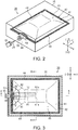
- the liquid containing portion 45 is configured by a liquid bag 42 substantially in the shape of a rectangle constituted by two film sheets 41 (see Fig. 4 ) whose outer periphery is sealed as indicated by the shaded region in Fig. 2 , and a joint member 50 that is inserted between the two film sheets 41 at one portion (one side) of the sealed outer periphery, wherein the two film sheets 41 are joined to both sides of the joint member 50.
- the liquid bag 42 is first formed in the shape of a bag by sealing flexible two film sheets 41 made of a resin material such that three of the four outer peripheral sides are adhered.
- the joint member 50 made of a resin material is inserted into an opening side of the liquid bag 42 constituted by one side that has not been sealed, that one side is adhered together with the joint member 50, so that a sealed portion 44 is formed at the outer periphery of the liquid bag 42 as indicated by the shaded region in Fig. 2 , and the inside of the liquid bag 42 can be used as the liquid containing portion 45. That is to say, the liquid containing portion 45 is an internal space defined by the liquid bag 42 and the joint member 50.
- the liquid containing portion 45 is a so-called ink bag constituted by the liquid bag 42 at least partially made of flexible film sheets 41, and the joint member 50.
- the flexible liquid bag 42 is deformed such that the gap between the two film sheets 41 facing each other is narrowed (the liquid bag 42 is flattened).
- the joint member 50 is provided with a liquid supply port 55 for supplying the ink contained in the liquid containing portion 45, that is, inside the liquid bag 42, to the liquid ejection head 13, in an exposed state where the liquid supply port 55 can be seen from the outside of the container casing 35.
- the liquid supply port 55 projects to the outside of the container casing 35 (see Fig. 3 ).
- supply needles 25 are provided on the front side in the direction in which the liquid containing members 30 are inserted.
- the corresponding supply needle 25 is inserted into the liquid supply port 55, so that ink flows out (is discharged) from the liquid supply port 55 to the supply needle 25.
- the ink that has flowed out to the supply needle 25 is supplied via the liquid supply tube 19 to the liquid ejection head 13, by the action of an unshown pump (e.g., diaphragm pump) provided in the casing 12.
- an unshown pump e.g., diaphragm pump
- a communication channel RR that is in communication with the liquid containing portion 45 and the liquid supply port 55 is provided in order to supply ink from the liquid containing portion 45 to the liquid ejection head 13. Furthermore, the communication channel RR includes liquid sucking portions that can suck ink contained in the liquid containing portion 45.
- the communication channel RR and the liquid sucking portions will be described with reference to the drawings.
- a first communication port 51 and a second communication port 52 are provided inside the liquid bag 42.
- the first communication port 51 and the second communication port 52 are arranged side by side substantially in the horizontal direction along the scanning direction X, in a state where the liquid containing member 30 is attached to the casing 12.
- Fig. 3 shows a state in which part of the film sheets 41 is cut away
- Fig. 4 shows cross-sections of the container casing 35 and the liquid bag 42 taken along lines indicated by arrows A-A and B-B in Fig. 3 .
- a first tube 61 having a predetermined length with both ends cut is attached to the first communication port 51 by pushing one of the cut tube ends into the first communication port 51, while a first end 61 a, which is the other cut tube end, is positioned substantially at the center in the conveyance direction Y in the liquid containing portion 45. Furthermore, a second tube 62 having a predetermined length with both ends cut is attached to the second communication port 52 by pushing one of the cut tube ends into the second communication port 52, while a second end 62a, which is the other cut tube end, is positioned substantially at the center in the conveyance direction Y in the liquid containing portion 45.
- a first channel R1 is constituted by the first tube 61 and the joint member 50 in which ink in the liquid containing portion 45 flows from the first tube 61 via the first communication port 51 to the liquid supply port 55.
- a second channel R2 is constituted by the second tube 62 and the joint member 50 in which ink in the liquid containing portion 45 flows from the second tube 62 via the second communication port 52 to the liquid supply port 55. That is to say, the first channel R1 and the second channel R2 constitute the communication channel RR that is in communication with the liquid containing portion 45 and the liquid supply port 55.
- the first end 61 a of the first tube 61 which is an end of the first channel R1
- the second end 62a of the second tube 62 is positioned at the upper end on the anti-gravity direction (-Z) side in the liquid containing portion 45.
- the first tube 61 is formed in a curved shape such that the first end 61 a is positioned at the lower end on the gravity direction (+Z) side in the liquid containing portion 45
- the second tube 62 is formed in a curved shape such that the second end 62a is positioned at the upper end on the anti-gravity direction (-Z) side in the liquid containing portion 45.
- the first end 61 a is positioned at the lower end on the gravity direction (+Z) side in the liquid containing portion 45 and functions as a first liquid sucking portion that can suck ink in the liquid containing portion 45. Furthermore, the second end 62a is positioned closer to the anti-gravity direction (-Z) side than the first end 61 a is, the first end 61 a functioning as the first liquid sucking portion. The second end 62a functions as a second liquid sucking portion that can suck ink in the liquid containing portion 45.
- the joint member 50 constituting the communication channel RR is included in the liquid containing member 30 so as to be positioned between the first end 61 a of the first tube 61 and the second end 62a of the second tube 62 in the vertical direction Z.
- the joint member 50 in a state where ink contained in the liquid containing portion 45 has not been consumed, the joint member 50 is included in the liquid containing member 30 such that the first communication port 51 and the second communication port 52 formed in the joint member 50 are positioned at the middle between the first end 61 a and the second end 62a in the vertical direction Z.
- Ink contained in the liquid containing portion 45 has a concentration distribution in which the pigment concentration is lowest on the upper end side and is highest on the lower end side in the liquid containing portion 45 as indicated by the black dots in part of the liquid containing portion 45 in Fig. 4 , because pigment is precipitated toward the gravity direction (+Z) side under its own weight.
- ink having a high pigment concentration is sucked from the first end 61 a (first liquid sucking portion) positioned at the lower end, and ink having a low pigment concentration is sucked from the second end 62a (second liquid sucking portion) positioned at the upper end.
- ink having a high pigment concentration sucked from the first end 61 a and ink having a low pigment concentration sucked from the second end 62a are mixed in the joint member 50 of the communication channel RR, so that the pigment concentration is averaged. That is to say, the communication channel RR mixes ink in the liquid containing portion 45, and causes it to flow out to the liquid supply port 55, as ink whose pigment concentration is averaged.
- the first end 61 a is kept at the lower end position in the liquid containing portion 45, that is, in a state of being in contact with the film sheet 41 on the gravity direction (+Z) side. Furthermore, the second end 62a is kept at the upper end position in the liquid containing portion 45, that is, in a state of being in contact with the film sheet 41 on the anti-gravity direction (-Z) side.
- a biasing member 70 may be provided that is connected between the first end 61 a and the second end 62a, and that biases the first end 61 a toward the gravity direction (+Z) side and biases the second end 62a toward the anti-gravity direction (-Z) side.
- Figs. 5 , 6, and 7 show views corresponding to Fig. 4 in the foregoing embodiment.
- a plate spring may be used that is an elastic band-like thin plate having a shape of being folded in two at a curved portion 70a provided substantially at the middle of the belt.
- one end side of the belt is provided with a first tubular portion 71 substantially in the shape of a circular tube
- the other end side of the belt is provided with a second tubular portion 72 substantially in the shape of a circular tube.
- a tube portion near the first end 61 a of the first tube 61 constituting the first channel R1 is inserted into the first tubular portion 71
- a tube portion near the second end 62a of the second tube 62 constituting the second channel R2 is inserted into the second tubular portion 72.
- the biasing member 70 is connected at the first tubular portion 71 and the second tubular portion 72 between the first end 61 a and the second end 62a.
- the first end 61 a and the second end 62a are biased away from each other, by a biasing force of the biasing member 70 generated by the first tubular portion 71 and the second tubular portion 72 moving closer to each other when the liquid bag 42 is flattened and the gap between the first end 61 a and the second end 62a is narrowed in the vertical direction Z.
- the first end 61 a is positioned and held at the lower end on the gravity direction (+Z) side in the liquid bag 42
- the second end 62a is positioned and held at the upper end on the anti-gravity direction (-Z) side in the liquid bag 42.
- a torsion spring may be used that is made of an elastic wire material having a shape in which a wound portion 75 that is helically wound is provided at the middle.
- the biasing member 70 constituted by this torsion spring
- one end side of the wire is provided with a first support portion 73 substantially in the shape of a semi-circle that supports a tube portion near the first end 61a of the first tube 61 from the anti-gravity direction (-Z) side.
- the other end side of the wire is provided with a second support portion 74 substantially in the shape of a semi-circle that supports a tube portion near the second end 62a of the second tube 62 from the gravity direction (+Z) side. That is to say, the biasing member 70 is connected at the first support portion 73 and the second support portion 74 between the first end 61 a and the second end 62a.
- the biasing member 70 is included in the liquid containing portion 45 such that the wound portion 75 has a winding axis along the scanning direction X, and is positioned between the first tube 61 and the second tube 62 in the scanning direction X.
- the first end 61 a and the second end 62a are biased away from each other, by a biasing force of the biasing member 70 generated by the first support portion 73 and the second support portion 74 respectively supporting the first tube 61 and the second tube 62 moving closer to each other when the liquid bag 42 is flattened and the gap between the first end 61 a and the second end 62a is narrowed in the vertical direction Z.
- the first end 61 a is positioned and held at the lower end on the gravity direction (+Z) side in the liquid bag 42
- the second end 62a is positioned and held at the upper end on the anti-gravity direction (-Z) side in the liquid bag 42.
- the biasing member 70 may be included in the liquid containing portion 45 such that the wound portion 75 that is helically wound has a winding axis along the conveyance direction Y, and is positioned away from the first tube 61 and the second tube 62 in the scanning direction X.
- the first support portion 73 supports a tube portion near the first end 61 a of the first tube 61 constituting the first channel R1 and biases it in the gravity direction (+Z)
- the second support portion 74 supports a tube portion near the second end 62a of the second tube 62 constituting the second channel R2 and biases it in the anti-gravity direction (-Z).
- the first end 61a and the second end 62a are biased away from each other by the biasing member 70, the first end 61 a is positioned and held at the lower end on the gravity direction (+Z) side in the liquid bag 42, and the second end 62a is positioned and held at the upper end on the anti-gravity direction (-Z) side in the liquid bag 42.
- At least a tube portion 63 having a predetermined length from the first end 61 a is made of a heavy material having a specific gravity that is larger than the specific gravity of the ink, as indicated by the dark shaded region in Fig. 8 .
- at least a tube portion 64 having a predetermined length from the second end 62a is made of a light material having a specific gravity that is smaller than the specific gravity of the ink, as indicated by the light shaded region in Fig. 8 .
- the first end 61 a and the second end 62a move so as to be respectively lowered and lifted away from each other in the ink liquid by the channel portions made of materials respectively having different specific gravities.
- the first end 61 a is positioned and held at the lower end on the gravity direction (+Z) side in the liquid bag 42 (in the ink liquid), and the second end 62a is positioned and held at the upper end on the anti-gravity direction (-Z) side in the liquid bag 42.
- the following effect can be obtained in addition to the effects (1) to (3) in the foregoing embodiment and the effect (4) in the foregoing modified example.
- the weight member 76 made of a heavy material having a specific gravity that is larger than the specific gravity of the ink is attached in a contact state at least to the anti-gravity direction (-Z) side of a tube portion near the first end 61 a, as indicated by the dark shaded region in Fig. 9 .
- the float member 77 made of a light material having a specific gravity that is smaller than the specific gravity of the ink is attached in a contact state at least to the gravity direction (+Z) side of a tube portion near the second end 62a, as indicated by the light shaded region in Fig. 9 .
- the weight member 76 is attached to the first channel R1
- the float member 77 is attached to the second channel R2.
- the first end 61 a and the second end 62a move so as to be respectively lowered and lifted away from each other in the ink liquid by the weight member 76 and the float member 77 made of materials respectively having different specific gravities.
- the first end 61 a is positioned and held at the lower end on the gravity direction (+Z) side in the liquid bag 42
- the second end 62a is positioned and held at the upper end on the anti-gravity direction (-Z) side in the liquid bag 42.
- Fig. 10 shows views corresponding to Fig. 4 in the foregoing embodiment.
- a first block member 81 substantially in the shape of a U constituted by three tube walls in which one of the tube walls of an angular tube is open is fixed to the film sheet 41 on the gravity direction (+Z) side in a state where a tube portion near the first end 61a of the first tube 61 is held in the U shape. That is to say, the first block member 81 is attached to the first end 61 a and fixed to the film sheet 41, so that the first end 61a is positioned in the liquid containing portion 45.
- a second block member 82 in the shape of an angular tube constituted by four tube walls is fixed to the film sheet 41 on the anti-gravity direction (-Z) side in a state where a tube portion near the second end 62a of the second tube 62 is held in the angular tube. That is to say, the second block member 82 is attached to the second end 62a and fixed to the film sheet 41, so that the second end 62a is positioned in the liquid containing portion 45.
- both of the first block member 81 and the second block member 82 may be substantially in the shape of a U in which one of the tube walls of an angular tube is open, or may be in the shape of an angular tube constituted by four tube walls. Furthermore, both of the first block member 81 and the second block member 82 do not necessarily have to be in the shape of an angular tube, and may be in the shape of a polygonal tube or a circular tube.
- the first block member 81 is made of the same material as the film sheets 41, and is fixed to the corresponding film sheet 41 such that two tube walls 81 a positioned on both sides in the scanning direction X of the first tube 61 and having an opening interposed therebetween are adhered, at portions thereof in contact with the film sheet 41, to the film sheet 41.
- the second block member 82 is made of the same material as the film sheets 41, and is fixed to the corresponding film sheet 41 such that one tube wall 82a constituting the angular tube is adhered, at a portion thereof in contact with the film sheet 41, to the film sheet 41.
- first end 61 a and the second end 62a are respectively positioned by the first block member 81 and the second block member 82, so that the first end 61 a is positioned and held at the lower end on the gravity direction (+Z) side in the liquid bag 42, and the second end 62a is positioned and held at the upper end on the anti-gravity direction (-Z) side in the liquid bag 42.
- first block member 81 or the second block member 82 may be made of a material different from that of the film sheets 41, and the block members may be fixed to the film sheets 41 by adhesion or bonding regardless of the material forming the block members.
- the first block member 81 can fix the position of the first end 61a in the scanning direction X in the liquid bag 42
- the second block member 82 can fix the position of the second end 62a in the scanning direction X in the liquid bag 42.
- the following effect can be obtained in addition to the effects (1) to (3) in the foregoing embodiment and the effect (4) in the foregoing modified example.
- the positioning units of the modified example shown in Fig. 10 may be additionally used in the modified examples shown in Figs. 5 to 9 . That is to say, block members (the first block member 81 and the second block member 82) that are respectively attached to the first channel R1 and the second channel R2 and adhered to the film sheets 41 so as to position the first end 61 a and the second end 62a in the liquid containing portion 45 may be provided so as to be included in the positioning units shown in Figs. 5 to 9 .
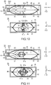
- a frame member 90 which is an example of a member that is inserted between the first tube 61 and the second tube 62 in the vertical direction Z and supports the first tube 61 (the first channel R1) and the second tube 62 (the second channel R2) in the liquid containing portion 45, may be provided as a positioning unit.
- Fig. 11 shows views corresponding to Fig. 4 in the foregoing embodiment.
- the frame member 90 is in the shape of a basket formed by combining a plurality of thin wires, wherein the first tube 61 is supported on the lower side that is the gravity direction (+Z) side of the basket, and the second tube 62 is supported on the upper side that is the anti-gravity direction (-Z) side of the basket. Accordingly, the first end 61 a of the first tube 61 is positioned and held by the frame member 90 at the lower end on the gravity direction (+Z) side in the liquid bag 42, and the second end 62a of the second tube 62 is positioned and held by the same at the upper end on the anti-gravity direction (-Z) side in the liquid bag 42.
- the frame member 90 can be deformed such that the basket-like shape is squeezed in the vertical direction Z, and the basket-like shape is deformed so as to be gradually squeezed in accordance with deformation of the liquid bag 42 due to consumption of ink in the liquid containing portion 45. At that time, the frame member 90 is deformed while continuously positioning the first end 61 a and the second end 62a in the liquid bag 42 (in the liquid containing portion 45), in accordance with squeezing of the basket-like shape.
- the following effect can be obtained in addition to the effects (1) to (3) in the foregoing embodiment and the effect (4) in the foregoing modified example.
- the positioning unit of the modified example shown in Fig. 11 may be additionally used in the modified examples shown in Figs. 5 to 9 . That is to say, a frame member 90 that is inserted between the first tube 61 and the second tube 62 and supports the first tube 61 (the first end 61 a) and the second tube 62 (the second end 62a) in the liquid containing portion 45 may be provided so as to be included in the positioning units shown in Figs. 5 to 9 .
- a first wire member 91 having one end that is fixed to the joint member 50 constituting the liquid containing portion 45 and a second wire member 92 also having one end that is fixed to the joint member 50 constituting the liquid containing portion 45 are provided as the frame member 90.
- Fig. 12 shows views corresponding to Fig. 4 in the foregoing embodiment.
- the first wire member 91 has the other end that is a first support portion 93 in the shape of a semi-circle that supports a tube portion near the first end 61 a of the first tube 61 from the upper side and holds the tube portion at the lower end in the liquid bag 42 (in the liquid containing portion 45).
- the second wire member 92 has the other end that is a second support portion 94 in the shape of a semi-circle that supports a tube portion near the second end 62a of the second tube 62 from the lower side and holds the tube portion at the upper end in the liquid bag 42.
- the frame member 90 can be deformed such that the first wire member 91 and the second wire member 92 are warped in the vertical direction Z, and is deformed so as to be gradually warped in the vertical direction Z in accordance with flattening of the liquid bag 42 due to consumption of ink in the liquid containing portion 45. Accordingly, in the liquid bag 42 that is being gradually flattened, the first end 61 a and the second end 62a move in the vertical direction Z, with its rotation in plane that intersects the conveyance direction Y restricted by the frame member 90.
- first wire member 91 and the second wire member 92 may be made of linear resin materials instead of metal, and respectively have ends that are fixed to the liquid bag 42 constituting the liquid containing portion 45.
- the following effect can be obtained in addition to the effects (1) to (3) in the foregoing embodiment and the effect (4) in the foregoing modified example.
- the positioning unit of the modified example shown in Fig. 12 may be additionally used in the modified examples shown in Figs. 5 to 9 . That is to say, a frame member 90 that is partially fixed to the liquid containing portion 45 may be provided so as to be included in the positioning units shown in Figs. 5 to 9 .
- Fig. 13 shows views corresponding to Fig. 4 in the foregoing embodiment.
- the first end 61 a of the first tube 61 is positioned at the lower end on the gravity direction (+Z) side in the liquid containing portion 45. Furthermore, the end 52a of the second communication port 52 is positioned closer to the anti-gravity direction (-Z) side than the first end 61a is, in the liquid containing portion 45.
- ink having a high pigment concentration is sucked from the first end 61 a (first liquid sucking portion) positioned at the lower end, and ink having a lower pigment concentration is sucked from the second communication port 52 (second liquid sucking portion).
- ink having a high pigment concentration sucked from the first end 61 a and ink having a low pigment concentration sucked from the second communication port 52 are mixed in the joint member 50, so that the pigment concentration is averaged.
- the joint member 50 is provided with one communication port 53 that is in communication with the liquid supply port 55, and a branched tube 60 having a branched channel in which one channel is branched into two channels is attached to the one communication port 53.
- Fig. 14 shows views corresponding to Fig. 4 in the foregoing embodiment.
- one channel side of the branched tube 60 is pushed into and attached to the communication port 53, wherein an end 67a of a branched first tube 67 having one branched channel of the branched two branched channels is positioned at the lower end on the gravity direction (+Z) side in the liquid containing portion 45 in an in-use state in which ink is supplied from the liquid supply port 55 to the liquid ejection head 13.
- an end 68a of a branched second tube 68 having the other branched channel of the branched two branched channels is positioned at the upper end on the anti-gravity direction (-Z) side in the liquid containing portion 45 in an in-use state in which ink is supplied from the liquid supply port 55 to the liquid ejection head 13.
- ink having a high pigment concentration is sucked from the end 67a (first liquid sucking portion) of the branched first tube 67 positioned at the lower end, and ink having a low pigment concentration is sucked from the end 68a (second liquid sucking portion) of the branched second tube 68 positioned at the upper end.
- ink having a high pigment concentration sucked from the end 67a and ink having a low pigment concentration sucked from the end 68a are mixed in the branched tube 60, so that ink whose pigment concentration is averaged is discharged to the liquid supply port 55.
- the liquid containing member 30 is formed such that its interior functions as the liquid containing portion 45. That is to say, the liquid containing member 30 has the container casing 35 that can internally contain ink without leakage, and a supply port member 56 that is provided at part of the container casing 35 and is provided with the liquid supply port 55.
- the supply port member 56 the first communication port 51 and the second communication port 52 that are in communication with the liquid supply port 55 are formed on the internal space side of the container casing 35, and, as in the foregoing embodiment, the first tube 61 and the second tube 62 are respectively attached to the first communication port 51 and the second communication port 52.
- the first end 61 a of the first tube 61 is positioned at the lower end on the gravity direction (+Z) side in the liquid containing portion 45. Furthermore, the second end 62a of the second tube 62 is positioned closer to the anti-gravity direction (-Z) side (upper end, in this example) than the first end 61 a of the first tube 61 is, in the liquid containing portion 45.
- the second tube 62 is made of a light material having a specific gravity that is smaller than the specific gravity of the ink, and, in the internal space of the container casing 35 as the liquid containing portion 45, the second end 62a of the second tube 62 is positioned near the ink surface, and is lowered together with the ink surface that is lowered in accordance with consumption of ink.
- ink having a high pigment concentration is sucked from the first end 61 a (first liquid sucking portion) of the first tube 61 positioned at the lower end, and ink having a low pigment concentration is sucked from the second end 62a (second liquid sucking portion) of the second tube 62.
- ink having a high pigment concentration sucked from the first tube 61 and ink having a low pigment concentration sucked from the second tube 62 are mixed in an unshown channel in the supply port member 56, so that ink whose pigment concentration is averaged is discharged to the liquid supply port 55.
- the first tube 61 and the second tube 62 are arranged such that the first end 61 a and the second end 62a that function as liquid sucking portions are positioned at the center of the liquid containing portion 45 in the scanning direction X, as shown in Fig. 15 .
- the biasing member 70 of the modified examples shown in Figs. 5 to 7 , the first tube 61 and the second tube 62 having channel portions having different specific gravities shown in Fig. 8 , the weight member 76 and the float member 77 shown in Fig. 9 , the block members shown in Fig. 10 , and the frame member 90 shown in Figs. 11 and 12 may be provided in the liquid containing member 30 of this modified example.
Landscapes
- Ink Jet (AREA)
Abstract
Description
- The present invention relates to a liquid containing member that can contain a liquid having a precipitating component.
- Inkjet printers have been known as an example of a liquid consuming apparatus that consumes a liquid (e.g., ink) having a precipitating component (e.g., pigment) by ejecting it from a liquid ejecting portion that can eject a liquid. In such printers, a liquid containing member (e.g., ink cartridge) including a liquid containing portion (e.g., ink pack (liquid bag)) that can contain a liquid is contained inside a printer casing, and a liquid is supplied from the liquid containing member contained inside the casing to the liquid ejecting portion.
- This liquid containing member is provided with a liquid supply port through which a liquid contained in the liquid containing portion is supplied to the liquid ejecting portion. The liquid supplied from the liquid supply port to the liquid ejecting portion has to be controlled such that a change in the concentration of the precipitating component is suppressed. The reason for this is that, if the concentration of the precipitating component in the liquid supplied from the liquid supply port is non-uniform, a liquid having a uniform concentration may not be ejected from the liquid ejecting portion. In this case, for example, when ejecting the liquid from the liquid ejecting portion onto paper and printing an image or the like thereon, the density of the printed image changes, resulting in a deterioration in the printing quality.
- Thus, in a liquid containing member in a related art, a liquid supply port (liquid discharge portion) is disposed at the center in the vertical direction of a liquid containing portion (ink pack), and liquid sucking portions (liquid sucking channels) that can suck a liquid (ink) are provided respectively at an upper portion on the anti-gravity direction side and a lower portion on the gravity direction side of the liquid supply port. If a liquid having a high concentration of the precipitating component and a liquid having a low concentration of the precipitating component are respectively sucked by the provided liquid sucking portions and mixed thereby, a liquid (ink) having a uniform concentration of the precipitating component is discharged from the liquid containing member (see
JP-A-2008-87486 - However, according to the liquid containing member in the related art, both the two liquid sucking portions provided at the upper and lower portions are positioned at the center in the vertical direction of the liquid containing portion, and thus, in the liquid containing portion, a liquid in the vicinity of the center near the liquid sucking portions is easily sucked out, whereas a liquid at the lower end on the gravity direction side or at the upper end on the anti-gravity direction side, far from the liquid sucking portions, is not easily sucked out. Accordingly, liquids having different concentrations tend to remain in the liquid containing portion, causing a problem that it becomes harder to supply (discharge) a liquid having a uniform concentration from the liquid containing member in accordance with the progress of the consumption of liquid.
- Note that such a situation is substantially shared by liquid containing members, including a liquid containing portion that can contain a liquid having a precipitating component, and a liquid supply port for supplying the liquid contained in the liquid containing portion to a liquid ejecting portion.
- An advantage of some aspects of the invention is to provide a liquid containing member that can supply a liquid having a uniform concentration of a precipitating component to a liquid ejecting portion.
- Hereinafter, means for solving the above-described problem and advantageous effects thereof will be described.
- A liquid containing member that solves the above-described problem is a liquid containing member capable of supplying a liquid having a precipitating component to a liquid ejecting portion. The liquid containing member includes: a liquid containing portion that can contain the liquid; a liquid supply port for supplying the liquid contained in the liquid containing portion to the liquid ejecting portion; and a communication channel that is in communication with the liquid containing portion and the liquid supply port. The communication channel has a first liquid sucking portion that is positioned at a lower end on the gravity direction side in the liquid containing portion and can suck the liquid, and a second liquid sucking portion that is positioned closer to the anti-gravity direction side than the first liquid sucking portion is, and can suck the liquid, in an in-use state in which the liquid is supplied from the liquid supply port to the liquid ejecting portion.
- With this configuration, a liquid having a comparatively high concentration of the precipitating component is sucked from the first liquid sucking portion, and a liquid having a comparatively low concentration of the precipitating component is sucked from the second liquid sucking portion, and these liquids are then mixed and caused to flow through the liquid supply port. Thus, a liquid having a uniform concentration of the precipitating component can be supplied to the liquid ejecting portion. Accordingly, for example, in the case of printing an image on paper using a liquid ejected from the liquid ejecting portion, a liquid having a uniform concentration of the precipitating component is ejected, and thus a deterioration in the printing quality can be suppressed.
- Preferably, the liquid containing member is such that, in the in-use state, the second liquid sucking portion is positioned at an upper end on the anti-gravity direction side in the liquid containing portion.
- With this configuration, liquids can be sucked from both the upper end and the lower end in the liquid containing portion and mixed to be supplied to the liquid ejecting portion, and thus, even when the consumption of liquid progresses, a liquid having a uniform concentration can be easily supplied to the liquid ejecting portion.
- Preferably, the liquid containing member is such that the communication channel has a first channel and a second channel, and the first liquid sucking portion is a first end that is in communication with the liquid containing portion in the first channel, and the second liquid sucking portion is a second end that is in communication with the liquid containing portion in the second channel.
- With this configuration, the liquid sucking portions are respectively an end of the first channel and an end of the second channel, and thus the liquid sucking portions can be easily positioned in the liquid containing portion.
- Preferably, the liquid containing member further includes a positioning unit that positions the first end of the first channel and the second end of the second channel in the liquid containing portion.
- With this configuration, the first end and the second end are positioned and held in the liquid containing portion, and thus positional shift of the liquid sucking portions in the liquid containing portion is suppressed.
- Preferably, the liquid containing member is such that the positioning unit is a biasing member that is connected between the first end and the second end, and that biases the first end toward the gravity direction side and biases the second end toward the anti-gravity direction side.
- With this configuration, with a positioning unit having a simple structure, the first end and the second end can be positioned in the liquid containing portion.
- Preferably, the liquid containing member is such that the positioning unit is channel portions made of materials respectively having different specific gravities with respect to the liquid, in the first channel and the second channel.
- With this configuration, with a simple structure, the first end and the second end can be positioned in the liquid containing portion.
- Preferably, the liquid containing member is such that the positioning unit is a weight member that is attached to the first channel and a float member that is attached to the second channel.
- With this configuration, with a simple structure, the first end and the second end can be positioned in the liquid containing portion.
- Preferably, the liquid containing member is such that the liquid containing portion is at least partially made of a film sheet, and the positioning unit includes a block member that is attached to the first end and the second end and is fixed to the film sheet.
- With this configuration, with a simple structure, the first end and the second end can be precisely positioned in the liquid containing portion.
- Preferably, the liquid containing member is such that the positioning unit includes a frame member that supports the first channel and the second channel in the liquid containing portion.
- With this configuration, with a simple structure, the first end and the second end can be precisely positioned in the liquid containing portion.
- Preferably, the liquid containing member is such that the frame member is partially fixed to a member constituting the liquid containing portion.
- With this configuration, the first end and the second end are prevented from rotating in the liquid containing portion, so that the first end and the second end can be reliably positioned in the liquid containing portion.
- The invention will be described with reference to the accompanying drawings, wherein like numbers reference like elements.
-
Fig. 1 shows a perspective view schematically showing, in a see-through state, the schematic configuration of an embodiment of a liquid consuming apparatus. -
Fig. 2 shows a perspective view showing, in a see-through state, a liquid containing member having a liquid containing portion containing a liquid that is to be supplied to a liquid ejecting portion. -
Fig. 3 shows a horizontal cross-sectional view showing the configuration of the liquid containing member in a state where part of the members is cut away. -
Fig. 4 shows cross-sectional views showing the configuration of the liquid containing member, wherein the upper portion is a cross-sectional view seen in the direction of arrows A-A inFig. 3 , and the lower portion is a cross-sectional view seen in the direction of arrows B-B inFig. 3 . -
Fig. 5 shows cross-sectional views showing an example of the configuration of a positioning unit for liquid sucking portions in the liquid containing portion. -
Fig. 6 shows cross-sectional views showing an example of the configuration of the positioning unit for the liquid sucking portions in the liquid containing portion. -
Fig. 7 shows cross-sectional views showing an example of the configuration of the positioning unit for the liquid sucking portions in the liquid containing portion. -
Fig. 8 shows cross-sectional views showing an example of the configuration of positioning units for the liquid sucking portions in the liquid containing portion. -
Fig. 9 shows cross-sectional views showing an example of the configuration of positioning units for the liquid sucking portions in the liquid containing portion. -
Fig. 10 shows cross-sectional views showing the configuration of the liquid containing portion including block members for positioning the liquid sucking portions. -
Fig. 11 shows cross-sectional views showing the configuration of the liquid containing portion including a frame member for positioning the liquid sucking portions. -
Fig. 12 shows cross-sectional views showing the configuration of the liquid containing portion to which the frame member for positioning the liquid sucking portions is fixed. -
Fig. 13 shows cross-sectional views showing a modified example of the configuration of the liquid sucking portions in the liquid containing portion. -
Fig. 14 shows cross-sectional views showing a modified example of the configuration of the liquid sucking portions in the liquid containing portion. -
Fig. 15 shows cross-sectional views showing a modified example of the configuration of the liquid containing member having the liquid containing portion. - Hereinafter, an embodiment of a liquid consuming apparatus will be described with reference to the drawings. The liquid consuming apparatus of this embodiment is an apparatus (e.g., printer) that records (prints) an image or the like on a medium by discharging ink, which is an example of a liquid, onto the medium.
- As shown in
Fig. 1 , a liquid consumingapparatus 11 of this embodiment includes aliquid ejection head 13, which is an example of a liquid ejecting portion that ejects ink onto paper P, which is an example of a medium that is being conveyed in one direction,liquid containing members 30 that can internally contain ink that is to be ejected by theliquid ejection head 13, and acasing 12 substantially in the shape of a rectangular parallelepiped that can internally contain theliquid containing members 30. InFig. 1 , the liquid consumingapparatus 11 is shown in a state where the internal portion is seen through thecasing 12. - The
liquid ejection head 13 is included in acarriage 16 that is supported on aguide shaft 14 provided inside thecasing 12 and having an axis extending in one direction, and that is driven by acarriage motor 15 to move back and forth in the axial direction of theguide shaft 14 inside thecasing 12 of theliquid consuming apparatus 11. - Specifically, the
guide shaft 14 is fixed at both ends thereof inside thecasing 12, and is inserted through a throughhole 16a that is formed through thecarriage 16. In thecasing 12, a drivingpulley 17a and a drivenpulley 17b are rotatably supported respectively near both ends of theguide shaft 14. An output shaft of thecarriage motor 15 is linked to the drivingpulley 17a, and anendless timing belt 18, part of which is linked to thecarriage 16, is wound around the drivingpulley 17a and the drivenpulley 17b. If thecarriage motor 15 is driven, thecarriage 16 is guided via thetiming belt 18 by theguide shaft 14 to move back and forth along the axial direction thereof, that is, along a scanning direction X. - The
liquid ejection head 13 is disposed on a gravity direction (+Z) side (also referred to as the lower side) in a vertical direction Z of thecarriage 16. The ink that is to be supplied to theliquid ejection head 13 is positioned closer to an anti-gravity direction (-Z) side (also referred to as the upper side) than the paper P is, the paper P being conveyed in a conveyance direction Y that intersects the scanning direction X, and is ejected from theliquid ejection head 13 that moves together with thecarriage 16 along the scanning direction X that matches the width direction of the paper P, so that an image or the like is recorded (printed) on the paper P. - The liquid containing
members 30 containing ink that is to be supplied to theliquid ejection head 13 can be contained inside thecasing 12. In this embodiment, theliquid containing members 30 are contained inside thecasing 12, at a corner of the casing 12 (corner in the horizontal direction), which is on the conveyance direction Y side toward which the paper P is conveyed during recording of an image or the like and one end side in the scanning direction X.Liquid supply tubes 19 through which ink can flow are linked between the liquid containingmembers 30 and thecarriage 16. The ink contained in theliquid containing members 30 is supplied via the linkedliquid supply tubes 19 to theliquid ejection head 13. - In this embodiment, four liquid containing
members 30 are substantially in the shape of rectangular parallelepipeds, and are contained inside thecasing 12 in a stacked state in which the sides in the thickness directions of the liquid containingmembers 30 are arranged on top of another along the vertical direction Z. The liquid containingmembers 30 contain ink having pigments, each of which is an example of a precipitating component (e.g., pigment ink having different colors, that is, the colors cyan, magenta, yellow, and black). - In this embodiment, in the
casing 12, a casing portion that faces theliquid containing members 30, on the front side of thecasing 12 positioned on the conveyance direction Y side toward which the paper P is conveyed, is provided as acover member 20 that can rotate about arotational shaft 21 provided on the lower side. If thecover member 20 is rotated (swung) about therotational shaft 21, theliquid containing members 30 are exposed, and a user can attach/detach or replace the liquid containingmembers 30 in a state where theliquid containing members 30 are exposed. - As shown in
Fig. 2 , theliquid containing members 30 have the same configuration, and each include aliquid containing portion 45 that can contain ink and acontainer casing 35 that internally contains theliquid containing portion 45. Theliquid containing portion 45 is configured by aliquid bag 42 substantially in the shape of a rectangle constituted by two film sheets 41 (seeFig. 4 ) whose outer periphery is sealed as indicated by the shaded region inFig. 2 , and ajoint member 50 that is inserted between the twofilm sheets 41 at one portion (one side) of the sealed outer periphery, wherein the twofilm sheets 41 are joined to both sides of thejoint member 50. - Specifically, the
liquid bag 42 is first formed in the shape of a bag by sealing flexible twofilm sheets 41 made of a resin material such that three of the four outer peripheral sides are adhered. Next, in a state where thejoint member 50 made of a resin material is inserted into an opening side of theliquid bag 42 constituted by one side that has not been sealed, that one side is adhered together with thejoint member 50, so that a sealedportion 44 is formed at the outer periphery of theliquid bag 42 as indicated by the shaded region inFig. 2 , and the inside of theliquid bag 42 can be used as theliquid containing portion 45. That is to say, theliquid containing portion 45 is an internal space defined by theliquid bag 42 and thejoint member 50. In other words, theliquid containing portion 45 is a so-called ink bag constituted by theliquid bag 42 at least partially made offlexible film sheets 41, and thejoint member 50. In accordance with a decrease in the volume of the liquid containingportion 45 due to flowing out of the ink, the flexibleliquid bag 42 is deformed such that the gap between the twofilm sheets 41 facing each other is narrowed (theliquid bag 42 is flattened). - The
joint member 50 is provided with aliquid supply port 55 for supplying the ink contained in theliquid containing portion 45, that is, inside theliquid bag 42, to theliquid ejection head 13, in an exposed state where theliquid supply port 55 can be seen from the outside of thecontainer casing 35. Note that, in this example, theliquid supply port 55 projects to the outside of the container casing 35 (seeFig. 3 ). Meanwhile, inside thecasing 12, supply needles 25 are provided on the front side in the direction in which theliquid containing members 30 are inserted. Thus, when each liquid containingmember 30 is attached to thecasing 12, the correspondingsupply needle 25 is inserted into theliquid supply port 55, so that ink flows out (is discharged) from theliquid supply port 55 to thesupply needle 25. The ink that has flowed out to thesupply needle 25 is supplied via theliquid supply tube 19 to theliquid ejection head 13, by the action of an unshown pump (e.g., diaphragm pump) provided in thecasing 12. - In the
liquid containing member 30 of this embodiment, a communication channel RR that is in communication with theliquid containing portion 45 and theliquid supply port 55 is provided in order to supply ink from theliquid containing portion 45 to theliquid ejection head 13. Furthermore, the communication channel RR includes liquid sucking portions that can suck ink contained in theliquid containing portion 45. Hereinafter, the communication channel RR and the liquid sucking portions will be described with reference to the drawings. - As shown in
Figs. 3 and4 , in thejoint member 50 where theliquid supply port 55 is formed, afirst communication port 51 and asecond communication port 52, both of which are in communication with theliquid supply port 55 in thejoint member 50, are provided inside theliquid bag 42. In this embodiment, thefirst communication port 51 and thesecond communication port 52 are arranged side by side substantially in the horizontal direction along the scanning direction X, in a state where theliquid containing member 30 is attached to thecasing 12. For the sake of ease of description,Fig. 3 shows a state in which part of thefilm sheets 41 is cut away, andFig. 4 shows cross-sections of thecontainer casing 35 and theliquid bag 42 taken along lines indicated by arrows A-A and B-B inFig. 3 . - A
first tube 61 having a predetermined length with both ends cut is attached to thefirst communication port 51 by pushing one of the cut tube ends into thefirst communication port 51, while afirst end 61 a, which is the other cut tube end, is positioned substantially at the center in the conveyance direction Y in theliquid containing portion 45. Furthermore, asecond tube 62 having a predetermined length with both ends cut is attached to thesecond communication port 52 by pushing one of the cut tube ends into thesecond communication port 52, while asecond end 62a, which is the other cut tube end, is positioned substantially at the center in the conveyance direction Y in theliquid containing portion 45. - Accordingly, in the
liquid containing member 30, a first channel R1 is constituted by thefirst tube 61 and thejoint member 50 in which ink in theliquid containing portion 45 flows from thefirst tube 61 via thefirst communication port 51 to theliquid supply port 55. Furthermore, in theliquid containing member 30, a second channel R2 is constituted by thesecond tube 62 and thejoint member 50 in which ink in theliquid containing portion 45 flows from thesecond tube 62 via thesecond communication port 52 to theliquid supply port 55. That is to say, the first channel R1 and the second channel R2 constitute the communication channel RR that is in communication with theliquid containing portion 45 and theliquid supply port 55. - In this embodiment, in an in-use state of the communication channel RR in which ink is supplied from the
liquid supply port 55 to theliquid ejection head 13, thefirst end 61 a of thefirst tube 61, which is an end of the first channel R1, is positioned at the lower end on the gravity direction (+Z) side in theliquid containing portion 45. Furthermore, thesecond end 62a of thesecond tube 62, which is an end of the second channel R2, is positioned at the upper end on the anti-gravity direction (-Z) side in theliquid containing portion 45. That is to say, in this embodiment, thefirst tube 61 is formed in a curved shape such that thefirst end 61 a is positioned at the lower end on the gravity direction (+Z) side in theliquid containing portion 45, and thesecond tube 62 is formed in a curved shape such that thesecond end 62a is positioned at the upper end on the anti-gravity direction (-Z) side in theliquid containing portion 45. - Accordingly, in an in-use state in which ink is supplied from the
liquid supply port 55 of the liquid containingmember 30 attached to the inside of thecasing 12 to theliquid ejection head 13, thefirst end 61 a is positioned at the lower end on the gravity direction (+Z) side in theliquid containing portion 45 and functions as a first liquid sucking portion that can suck ink in theliquid containing portion 45. Furthermore, thesecond end 62a is positioned closer to the anti-gravity direction (-Z) side than thefirst end 61 a is, thefirst end 61 a functioning as the first liquid sucking portion. Thesecond end 62a functions as a second liquid sucking portion that can suck ink in theliquid containing portion 45. - The
joint member 50 constituting the communication channel RR is included in theliquid containing member 30 so as to be positioned between thefirst end 61 a of thefirst tube 61 and thesecond end 62a of thesecond tube 62 in the vertical direction Z. Incidentally, in this embodiment, in a state where ink contained in theliquid containing portion 45 has not been consumed, thejoint member 50 is included in theliquid containing member 30 such that thefirst communication port 51 and thesecond communication port 52 formed in thejoint member 50 are positioned at the middle between thefirst end 61 a and thesecond end 62a in the vertical direction Z. - Hereinafter, an action of each liquid containing
member 30 of this embodiment will be described. - Ink contained in the
liquid containing portion 45 has a concentration distribution in which the pigment concentration is lowest on the upper end side and is highest on the lower end side in theliquid containing portion 45 as indicated by the black dots in part of the liquid containingportion 45 inFig. 4 , because pigment is precipitated toward the gravity direction (+Z) side under its own weight. - According to the
liquid containing member 30 of this embodiment, in theliquid containing portion 45, ink having a high pigment concentration is sucked from thefirst end 61 a (first liquid sucking portion) positioned at the lower end, and ink having a low pigment concentration is sucked from thesecond end 62a (second liquid sucking portion) positioned at the upper end. As a result, ink having a high pigment concentration sucked from thefirst end 61 a and ink having a low pigment concentration sucked from thesecond end 62a are mixed in thejoint member 50 of the communication channel RR, so that the pigment concentration is averaged. That is to say, the communication channel RR mixes ink in theliquid containing portion 45, and causes it to flow out to theliquid supply port 55, as ink whose pigment concentration is averaged. - Although not shown, even in a state where the consumption of ink in the
liquid containing portion 45 progresses and the gap between the twofilm sheets 41 is narrowed, that is, theliquid bag 42 is flattened, thefirst end 61 a is kept at the lower end position in theliquid containing portion 45, that is, in a state of being in contact with thefilm sheet 41 on the gravity direction (+Z) side. Furthermore, thesecond end 62a is kept at the upper end position in theliquid containing portion 45, that is, in a state of being in contact with thefilm sheet 41 on the anti-gravity direction (-Z) side. - According to the above-described embodiment, the following effects can be obtained.
- (1) Ink having a comparatively high pigment concentration is sucked from the
first end 61 a, and ink having a comparatively low pigment concentration is sucked from thesecond end 62a, which are then mixed and caused to flow through theliquid supply port 55, and thus ink having a uniform pigment concentration can be supplied to theliquid ejection head 13. Accordingly, for example, in the case of printing an image on the paper P using ink ejected from theliquid ejection head 13, ink having a uniform pigment concentration is ejected, and thus a deterioration in the printing quality can be suppressed. - (2) Ink can be sucked from both the upper end and the lower end in the
liquid containing portion 45 and mixed to be supplied to theliquid ejection head 13, and thus, even when the consumption of ink progresses, ink having a uniform concentration can be easily supplied to theliquid ejection head 13. - (3) The
first end 61 a functioning as the first liquid sucking portion and thesecond end 62a functioning as the second liquid sucking portion are respectively an end of the first channel R1 and an end of the second channel R2 constituting the communication channel RR, and thus the first liquid sucking portion and the second liquid sucking portion can be easily positioned in theliquid containing portion 45. Furthermore, the first liquid sucking portion and the second liquid sucking portion are tube ends (thefirst end 61 a and thesecond end 62a) formed by cutting thefirst tube 61 and thesecond tube 62, and thus these liquid sucking portions can be easily produced in theliquid containing portion 45. - Note that the foregoing embodiment may be modified into the following other embodiments.
- In the foregoing embodiment, a positioning unit that positions the
first end 61 a of the first channel R1 and thesecond end 62a of the second channel R2 without positional shift in theliquid containing portion 45 may be provided. Hereinafter, this modified example will be described with reference to the drawings. - As shown in
Figs. 5 ,6, and 7 , as a positioning unit, a biasingmember 70 may be provided that is connected between thefirst end 61 a and thesecond end 62a, and that biases thefirst end 61 a toward the gravity direction (+Z) side and biases thesecond end 62a toward the anti-gravity direction (-Z) side.Figs. 5 ,6, and 7 show views corresponding toFig. 4 in the foregoing embodiment. - First, as shown in
Fig. 5 , as the biasingmember 70, a plate spring may be used that is an elastic band-like thin plate having a shape of being folded in two at acurved portion 70a provided substantially at the middle of the belt. - In the biasing
member 70, one end side of the belt is provided with a firsttubular portion 71 substantially in the shape of a circular tube, and the other end side of the belt is provided with a secondtubular portion 72 substantially in the shape of a circular tube. A tube portion near thefirst end 61 a of thefirst tube 61 constituting the first channel R1 is inserted into the firsttubular portion 71, and a tube portion near thesecond end 62a of thesecond tube 62 constituting the second channel R2 is inserted into the secondtubular portion 72. In other words, the biasingmember 70 is connected at the firsttubular portion 71 and the secondtubular portion 72 between thefirst end 61 a and thesecond end 62a. - The
first end 61 a and thesecond end 62a are biased away from each other, by a biasing force of the biasingmember 70 generated by the firsttubular portion 71 and the secondtubular portion 72 moving closer to each other when theliquid bag 42 is flattened and the gap between thefirst end 61 a and thesecond end 62a is narrowed in the vertical direction Z. As a result, thefirst end 61 a is positioned and held at the lower end on the gravity direction (+Z) side in theliquid bag 42, and thesecond end 62a is positioned and held at the upper end on the anti-gravity direction (-Z) side in theliquid bag 42. - Alternatively, as shown in
Fig. 6 , as the biasingmember 70, a torsion spring may be used that is made of an elastic wire material having a shape in which awound portion 75 that is helically wound is provided at the middle. - In the biasing
member 70 constituted by this torsion spring, one end side of the wire is provided with afirst support portion 73 substantially in the shape of a semi-circle that supports a tube portion near thefirst end 61a of thefirst tube 61 from the anti-gravity direction (-Z) side. Furthermore, the other end side of the wire is provided with asecond support portion 74 substantially in the shape of a semi-circle that supports a tube portion near thesecond end 62a of thesecond tube 62 from the gravity direction (+Z) side. That is to say, the biasingmember 70 is connected at thefirst support portion 73 and thesecond support portion 74 between thefirst end 61 a and thesecond end 62a. Furthermore, the biasingmember 70 is included in theliquid containing portion 45 such that thewound portion 75 has a winding axis along the scanning direction X, and is positioned between thefirst tube 61 and thesecond tube 62 in the scanning direction X. - The
first end 61 a and thesecond end 62a are biased away from each other, by a biasing force of the biasingmember 70 generated by thefirst support portion 73 and thesecond support portion 74 respectively supporting thefirst tube 61 and thesecond tube 62 moving closer to each other when theliquid bag 42 is flattened and the gap between thefirst end 61 a and thesecond end 62a is narrowed in the vertical direction Z. As a result, thefirst end 61 a is positioned and held at the lower end on the gravity direction (+Z) side in theliquid bag 42, and thesecond end 62a is positioned and held at the upper end on the anti-gravity direction (-Z) side in theliquid bag 42. - Alternatively, as shown in
Fig. 7 , in the case of using a torsion spring made of a wire material as the biasingmember 70, the biasingmember 70 may be included in theliquid containing portion 45 such that thewound portion 75 that is helically wound has a winding axis along the conveyance direction Y, and is positioned away from thefirst tube 61 and thesecond tube 62 in the scanning direction X. - As in the biasing
member 70 shown inFig. 6 , thefirst support portion 73 supports a tube portion near thefirst end 61 a of thefirst tube 61 constituting the first channel R1 and biases it in the gravity direction (+Z), and thesecond support portion 74 supports a tube portion near thesecond end 62a of thesecond tube 62 constituting the second channel R2 and biases it in the anti-gravity direction (-Z). Accordingly, thefirst end 61a and thesecond end 62a are biased away from each other by the biasingmember 70, thefirst end 61 a is positioned and held at the lower end on the gravity direction (+Z) side in theliquid bag 42, and thesecond end 62a is positioned and held at the upper end on the anti-gravity direction (-Z) side in theliquid bag 42. - According to the modified examples in
Figs. 5 to 7 , the following effects can be obtained in addition to the effects (1) to (3) in the foregoing embodiment. - (4) The
first end 61a and thesecond end 62a are positioned and held in theliquid containing portion 45, and thus positional shift of the first liquid sucking portion and the second liquid sucking portion is suppressed. - (5) With the biasing
member 70 that is a positioning unit having a simple structure, thefirst end 61 a that is the first liquid sucking portion and thesecond end 62a that is the second liquid sucking portion can be positioned in theliquid containing portion 45.- Alternatively, as shown in
Fig. 8 , in the first channel R1 and the second channel R2, channel portions are made of materials respectively having different specific gravities with respect to ink, and the formed channel portions having different specific gravities may be provided as positioning units respectively for thefirst end 61 a and thesecond end 62a.Fig. 8 shows views corresponding toFig. 4 in the foregoing embodiment.
- Alternatively, as shown in
- In this modified example, in the
first tube 61 constituting the first channel R1, at least atube portion 63 having a predetermined length from thefirst end 61 a is made of a heavy material having a specific gravity that is larger than the specific gravity of the ink, as indicated by the dark shaded region inFig. 8 . On the other hand, in thesecond tube 62 constituting the second channel R2, at least atube portion 64 having a predetermined length from thesecond end 62a is made of a light material having a specific gravity that is smaller than the specific gravity of the ink, as indicated by the light shaded region inFig. 8 . Accordingly, thefirst end 61 a and thesecond end 62a move so as to be respectively lowered and lifted away from each other in the ink liquid by the channel portions made of materials respectively having different specific gravities. As a result, thefirst end 61 a is positioned and held at the lower end on the gravity direction (+Z) side in the liquid bag 42 (in the ink liquid), and thesecond end 62a is positioned and held at the upper end on the anti-gravity direction (-Z) side in theliquid bag 42. - According to the modified example shown in
Fig. 8 , the following effect can be obtained in addition to the effects (1) to (3) in the foregoing embodiment and the effect (4) in the foregoing modified example. - (6) With a simple structure, the
first end 61a and thesecond end 62a can be positioned in theliquid containing portion 45. Furthermore, in the case where the first channel R1 and the second channel R2 are made of materials having different specific gravities, the positioning units can be easily produced without increasing the number of parts.- Alternatively, as shown in
Fig. 9 , aweight member 76 attached to the first channel R1 and afloat member 77 attached to the second channel R2 may be provided as positioning units.Fig. 9 shows views corresponding toFig. 4 in the foregoing embodiment.
- Alternatively, as shown in
- In this modified example, in the
first tube 61 constituting the first channel R1, theweight member 76 made of a heavy material having a specific gravity that is larger than the specific gravity of the ink is attached in a contact state at least to the anti-gravity direction (-Z) side of a tube portion near thefirst end 61 a, as indicated by the dark shaded region inFig. 9 . Furthermore, in thesecond tube 62 constituting the second channel R2, thefloat member 77 made of a light material having a specific gravity that is smaller than the specific gravity of the ink is attached in a contact state at least to the gravity direction (+Z) side of a tube portion near thesecond end 62a, as indicated by the light shaded region inFig. 9 . In other words, theweight member 76 is attached to the first channel R1, and thefloat member 77 is attached to the second channel R2. Accordingly, thefirst end 61 a and thesecond end 62a move so as to be respectively lowered and lifted away from each other in the ink liquid by theweight member 76 and thefloat member 77 made of materials respectively having different specific gravities. As a result, thefirst end 61 a is positioned and held at the lower end on the gravity direction (+Z) side in theliquid bag 42, and thesecond end 62a is positioned and held at the upper end on the anti-gravity direction (-Z) side in theliquid bag 42. - According to the modified example shown in
Fig. 9 , the following effect can be obtained in addition to the effects (1) to (3) in the foregoing embodiment and the effect (4) in the foregoing modified example. - (7) With a simple structure, the
first end 61a and thesecond end 62a can be positioned in theliquid containing portion 45.- In the foregoing embodiment, positioning units that position the
first end 61 a of the first channel R1 and thesecond end 62a of the second channel R2 in theliquid containing portion 45 without biasing the ends may be provided. This modified example will be described with reference to the drawings.
- In the foregoing embodiment, positioning units that position the
- As shown in
Fig. 10 , as the positioning units, block members respectively attached to thefirst end 61 a and thesecond end 62a and fixed to thefilm sheets 41 may be provided.Fig. 10 shows views corresponding toFig. 4 in the foregoing embodiment. - In this modified example, as a block member, a
first block member 81 substantially in the shape of a U constituted by three tube walls in which one of the tube walls of an angular tube is open is fixed to thefilm sheet 41 on the gravity direction (+Z) side in a state where a tube portion near thefirst end 61a of thefirst tube 61 is held in the U shape. That is to say, thefirst block member 81 is attached to thefirst end 61 a and fixed to thefilm sheet 41, so that thefirst end 61a is positioned in theliquid containing portion 45. Furthermore, as another block member, asecond block member 82 in the shape of an angular tube constituted by four tube walls is fixed to thefilm sheet 41 on the anti-gravity direction (-Z) side in a state where a tube portion near thesecond end 62a of thesecond tube 62 is held in the angular tube. That is to say, thesecond block member 82 is attached to thesecond end 62a and fixed to thefilm sheet 41, so that thesecond end 62a is positioned in theliquid containing portion 45. - Note that, in this modified example, both of the
first block member 81 and thesecond block member 82 may be substantially in the shape of a U in which one of the tube walls of an angular tube is open, or may be in the shape of an angular tube constituted by four tube walls. Furthermore, both of thefirst block member 81 and thesecond block member 82 do not necessarily have to be in the shape of an angular tube, and may be in the shape of a polygonal tube or a circular tube. - In this modified example, the
first block member 81 is made of the same material as thefilm sheets 41, and is fixed to thecorresponding film sheet 41 such that twotube walls 81 a positioned on both sides in the scanning direction X of thefirst tube 61 and having an opening interposed therebetween are adhered, at portions thereof in contact with thefilm sheet 41, to thefilm sheet 41. Furthermore, thesecond block member 82 is made of the same material as thefilm sheets 41, and is fixed to thecorresponding film sheet 41 such that onetube wall 82a constituting the angular tube is adhered, at a portion thereof in contact with thefilm sheet 41, to thefilm sheet 41. Accordingly, thefirst end 61 a and thesecond end 62a are respectively positioned by thefirst block member 81 and thesecond block member 82, so that thefirst end 61 a is positioned and held at the lower end on the gravity direction (+Z) side in theliquid bag 42, and thesecond end 62a is positioned and held at the upper end on the anti-gravity direction (-Z) side in theliquid bag 42. It will be appreciated that thefirst block member 81 or thesecond block member 82 may be made of a material different from that of thefilm sheets 41, and the block members may be fixed to thefilm sheets 41 by adhesion or bonding regardless of the material forming the block members. - Note that, in this modified example, the
first block member 81 can fix the position of thefirst end 61a in the scanning direction X in theliquid bag 42, and thesecond block member 82 can fix the position of thesecond end 62a in the scanning direction X in theliquid bag 42. - According to the modified example shown in
Fig. 10 , the following effect can be obtained in addition to the effects (1) to (3) in the foregoing embodiment and the effect (4) in the foregoing modified example. - (8) With a simple structure, the
first end 61a and thesecond end 62a can be precisely positioned in theliquid containing portion 45. As a result, for example, if thefirst end 61 a is precisely positioned at the lowest position in theliquid containing portion 45, the amount of ink remaining in theliquid containing portion 45 can be made as small as possible. - The positioning units of the modified example shown in
Fig. 10 may be additionally used in the modified examples shown inFigs. 5 to 9 . That is to say, block members (thefirst block member 81 and the second block member 82) that are respectively attached to the first channel R1 and the second channel R2 and adhered to thefilm sheets 41 so as to position thefirst end 61 a and thesecond end 62a in theliquid containing portion 45 may be provided so as to be included in the positioning units shown inFigs. 5 to 9 . - In the foregoing embodiment, a member that supports the first channel R1 and the second channel R2 in the
liquid containing portion 45 may be provided as a positioning unit for thefirst end 61 a and thesecond end 62a. This modified example will be described with reference to the drawings. - As shown in
Fig. 11 , aframe member 90, which is an example of a member that is inserted between thefirst tube 61 and thesecond tube 62 in the vertical direction Z and supports the first tube 61 (the first channel R1) and the second tube 62 (the second channel R2) in theliquid containing portion 45, may be provided as a positioning unit.Fig. 11 shows views corresponding toFig. 4 in the foregoing embodiment. - In this modified example, the
frame member 90 is in the shape of a basket formed by combining a plurality of thin wires, wherein thefirst tube 61 is supported on the lower side that is the gravity direction (+Z) side of the basket, and thesecond tube 62 is supported on the upper side that is the anti-gravity direction (-Z) side of the basket. Accordingly, thefirst end 61 a of thefirst tube 61 is positioned and held by theframe member 90 at the lower end on the gravity direction (+Z) side in theliquid bag 42, and thesecond end 62a of thesecond tube 62 is positioned and held by the same at the upper end on the anti-gravity direction (-Z) side in theliquid bag 42. - Although not shown, the
frame member 90 can be deformed such that the basket-like shape is squeezed in the vertical direction Z, and the basket-like shape is deformed so as to be gradually squeezed in accordance with deformation of theliquid bag 42 due to consumption of ink in theliquid containing portion 45. At that time, theframe member 90 is deformed while continuously positioning thefirst end 61 a and thesecond end 62a in the liquid bag 42 (in the liquid containing portion 45), in accordance with squeezing of the basket-like shape. - According to the modified example shown in
Fig. 11 , the following effect can be obtained in addition to the effects (1) to (3) in the foregoing embodiment and the effect (4) in the foregoing modified example. - (9) With a simple structure, the
first end 61 a and thesecond end 62a can be precisely positioned in theliquid containing portion 45. - The positioning unit of the modified example shown in
Fig. 11 may be additionally used in the modified examples shown inFigs. 5 to 9 . That is to say, aframe member 90 that is inserted between thefirst tube 61 and thesecond tube 62 and supports the first tube 61 (thefirst end 61 a) and the second tube 62 (thesecond end 62a) in theliquid containing portion 45 may be provided so as to be included in the positioning units shown inFigs. 5 to 9 . - In the foregoing embodiment, as an example of a support member that supports the
first end 61 a of the first channel R1 and thesecond end 62a of the second channel R2 in theliquid containing portion 45, aframe member 90 that is partially fixed to a member constituting theliquid containing portion 45 may be provided as a positioning unit. This modified example will be described with reference to the drawings. - As shown in
Fig. 12 , in this modified example, afirst wire member 91 having one end that is fixed to thejoint member 50 constituting theliquid containing portion 45 and asecond wire member 92 also having one end that is fixed to thejoint member 50 constituting theliquid containing portion 45 are provided as theframe member 90.Fig. 12 shows views corresponding toFig. 4 in the foregoing embodiment. - In the
frame member 90 of this modified example, thefirst wire member 91 has the other end that is afirst support portion 93 in the shape of a semi-circle that supports a tube portion near thefirst end 61 a of thefirst tube 61 from the upper side and holds the tube portion at the lower end in the liquid bag 42 (in the liquid containing portion 45). Furthermore, thesecond wire member 92 has the other end that is asecond support portion 94 in the shape of a semi-circle that supports a tube portion near thesecond end 62a of thesecond tube 62 from the lower side and holds the tube portion at the upper end in theliquid bag 42. Accordingly, movement of thefirst end 61 a and thesecond end 62a in the scanning direction X or in the vertical direction Z is restricted in theliquid bag 42 by theframe member 90 having ends that are fixed to thejoint member 50. In other words, rotation of thefirst end 61 a and thesecond end 62a is restricted in plane that intersects the conveyance direction Y in theliquid containing portion 45. - The
frame member 90 can be deformed such that thefirst wire member 91 and thesecond wire member 92 are warped in the vertical direction Z, and is deformed so as to be gradually warped in the vertical direction Z in accordance with flattening of theliquid bag 42 due to consumption of ink in theliquid containing portion 45. Accordingly, in theliquid bag 42 that is being gradually flattened, thefirst end 61 a and thesecond end 62a move in the vertical direction Z, with its rotation in plane that intersects the conveyance direction Y restricted by theframe member 90. - Note that, in this modified example, the
first wire member 91 and thesecond wire member 92 may be made of linear resin materials instead of metal, and respectively have ends that are fixed to theliquid bag 42 constituting theliquid containing portion 45. - According to the modified example shown in
Fig. 12 , the following effect can be obtained in addition to the effects (1) to (3) in the foregoing embodiment and the effect (4) in the foregoing modified example. - (10) The
first end 61 a and thesecond end 62a are prevented from rotating in theliquid containing portion 45, so that thefirst end 61 a and thesecond end 62a can be reliably positioned in theliquid containing portion 45. - It will be appreciated that the positioning unit of the modified example shown in
Fig. 12 may be additionally used in the modified examples shown inFigs. 5 to 9 . That is to say, aframe member 90 that is partially fixed to theliquid containing portion 45 may be provided so as to be included in the positioning units shown inFigs. 5 to 9 . - In the foregoing embodiment, the
second end 62a as the second liquid sucking portion does not necessarily have to be positioned at the upper end on the anti-gravity direction (-Z) side in theliquid containing portion 45 in an in-use state, and may be positioned anywhere as long as it is positioned closer to the anti-gravity direction (-Z) side than thefirst end 61 a as the first liquid sucking portion is. This modified example will be described with reference to the drawings. - As shown in
Fig. 13 , in this modified example, thesecond tube 62 is removed from thesecond communication port 52 of thejoint member 50, and anend 52a of thesecond communication port 52, which becomes an end of the second channel R2, is provided as the second liquid sucking portion.Fig. 13 shows views corresponding toFig. 4 in the foregoing embodiment. - In this modified example, in an in-use state in which ink is supplied from the
liquid supply port 55 to theliquid ejection head 13, thefirst end 61 a of thefirst tube 61 is positioned at the lower end on the gravity direction (+Z) side in theliquid containing portion 45. Furthermore, theend 52a of thesecond communication port 52 is positioned closer to the anti-gravity direction (-Z) side than thefirst end 61a is, in theliquid containing portion 45. - Accordingly, as indicated by the black dots in part of the liquid containing
portion 45 inFig. 13 , ink having a high pigment concentration is sucked from thefirst end 61 a (first liquid sucking portion) positioned at the lower end, and ink having a lower pigment concentration is sucked from the second communication port 52 (second liquid sucking portion). As a result, ink having a high pigment concentration sucked from thefirst end 61 a and ink having a low pigment concentration sucked from thesecond communication port 52 are mixed in thejoint member 50, so that the pigment concentration is averaged. - In the foregoing embodiment, the communication channel RR does not necessarily have to have a configuration in which its channels join together in the
joint member 50 provided with thefirst communication port 51 and thesecond communication port 52. This modified example will be described with reference to the drawings. - As shown in
Fig. 14 , in this modified example, thejoint member 50 is provided with onecommunication port 53 that is in communication with theliquid supply port 55, and abranched tube 60 having a branched channel in which one channel is branched into two channels is attached to the onecommunication port 53.Fig. 14 shows views corresponding toFig. 4 in the foregoing embodiment. - In this modified example, one channel side of the branched
tube 60 is pushed into and attached to thecommunication port 53, wherein an end 67a of a branchedfirst tube 67 having one branched channel of the branched two branched channels is positioned at the lower end on the gravity direction (+Z) side in theliquid containing portion 45 in an in-use state in which ink is supplied from theliquid supply port 55 to theliquid ejection head 13. Furthermore, anend 68a of a branchedsecond tube 68 having the other branched channel of the branched two branched channels is positioned at the upper end on the anti-gravity direction (-Z) side in theliquid containing portion 45 in an in-use state in which ink is supplied from theliquid supply port 55 to theliquid ejection head 13. - Accordingly, in this modified example, as shown in
Fig. 4 in the foregoing embodiment, ink having a high pigment concentration is sucked from the end 67a (first liquid sucking portion) of the branchedfirst tube 67 positioned at the lower end, and ink having a low pigment concentration is sucked from theend 68a (second liquid sucking portion) of the branchedsecond tube 68 positioned at the upper end. As a result, ink having a high pigment concentration sucked from the end 67a and ink having a low pigment concentration sucked from theend 68a are mixed in the branchedtube 60, so that ink whose pigment concentration is averaged is discharged to theliquid supply port 55. - In the foregoing embodiment, at least a portion of the liquid containing
portion 45 may not be made of film sheets. This modified example will be described with reference to the drawings. - As shown in
Fig. 15 , in this modified example, theliquid containing member 30 is formed such that its interior functions as theliquid containing portion 45. That is to say, theliquid containing member 30 has thecontainer casing 35 that can internally contain ink without leakage, and asupply port member 56 that is provided at part of thecontainer casing 35 and is provided with theliquid supply port 55. In thesupply port member 56, thefirst communication port 51 and thesecond communication port 52 that are in communication with theliquid supply port 55 are formed on the internal space side of thecontainer casing 35, and, as in the foregoing embodiment, thefirst tube 61 and thesecond tube 62 are respectively attached to thefirst communication port 51 and thesecond communication port 52. - In an in-use state in which ink is supplied from the
liquid supply port 55 to theliquid ejection head 13, thefirst end 61 a of thefirst tube 61 is positioned at the lower end on the gravity direction (+Z) side in theliquid containing portion 45. Furthermore, thesecond end 62a of thesecond tube 62 is positioned closer to the anti-gravity direction (-Z) side (upper end, in this example) than thefirst end 61 a of thefirst tube 61 is, in theliquid containing portion 45. In this modified example, for example, thesecond tube 62 is made of a light material having a specific gravity that is smaller than the specific gravity of the ink, and, in the internal space of thecontainer casing 35 as theliquid containing portion 45, thesecond end 62a of thesecond tube 62 is positioned near the ink surface, and is lowered together with the ink surface that is lowered in accordance with consumption of ink. - With this configuration, in this modified example, as shown in
Fig. 4 in the foregoing embodiment, ink having a high pigment concentration is sucked from thefirst end 61 a (first liquid sucking portion) of thefirst tube 61 positioned at the lower end, and ink having a low pigment concentration is sucked from thesecond end 62a (second liquid sucking portion) of thesecond tube 62. As a result, ink having a high pigment concentration sucked from thefirst tube 61 and ink having a low pigment concentration sucked from thesecond tube 62 are mixed in an unshown channel in thesupply port member 56, so that ink whose pigment concentration is averaged is discharged to theliquid supply port 55. - In the
liquid containing member 30 of this modified example, It is preferable that thefirst tube 61 and thesecond tube 62 are arranged such that thefirst end 61 a and thesecond end 62a that function as liquid sucking portions are positioned at the center of the liquid containingportion 45 in the scanning direction X, as shown inFig. 15 . Thus, the biasingmember 70 of the modified examples shown inFigs. 5 to 7 , thefirst tube 61 and thesecond tube 62 having channel portions having different specific gravities shown inFig. 8 , theweight member 76 and thefloat member 77 shown inFig. 9 , the block members shown inFig. 10 , and theframe member 90 shown inFigs. 11 and12 may be provided in theliquid containing member 30 of this modified example. - In the foregoing embodiment, the first liquid sucking portion does not necessarily have to be the
first end 61 a that is in communication with theliquid containing portion 45 in the first channel R1. Alternatively, the second liquid sucking portion does not necessarily have to be thesecond end 62a that is in communication with theliquid containing portion 45 in the second channel R2. Although not shown, for example, the first liquid sucking portion may not be a tube end of thefirst tube 61 but may be one or a plurality of holes provided partway along the tube. Furthermore, the second liquid sucking portion may not be a tube end of thesecond tube 62 but may be one or a plurality of holes provided partway along the tube. - In the foregoing embodiment, the
liquid containing member 30 may be provided outside thecasing 12 of theliquid consuming apparatus 11. In the case where ink is supplied from theliquid containing member 30 provided outside thecasing 12 to theliquid ejection head 13 inside thecasing 12, for example, theliquid supply tubes 19 for supplying the ink may be arranged from the outside of thecasing 12 via a gap provided at thecasing 12 into the inside of thecasing 12. - In the foregoing embodiment, the medium is not limited to the paper P, and the medium may be a plastic film, a thin plate material, or the like, or may be a fabric used in a textile printing device and the like.
- In the foregoing embodiment, the
liquid consuming apparatus 11 may not be provided with thecarriage 16, and may be changed to a so-called full-line apparatus (printer) including a fixed longliquid ejection head 13 corresponding to the fill width of the paper P. Theliquid ejection head 13 in this case may be a plurality of unit heads that are arranged side by side such that the recording range covers the full width of the paper P, or may be a single long head that is disposed so as to extend across the full width of the paper P such that the recording range covers the full width of the paper P. - In the foregoing embodiment, the
liquid consuming apparatus 11 may be an apparatus that ejects or discharges a liquid other than ink. Note that the states of the liquid discharged as very small droplets from the liquid consuming apparatus include a granular shape, a tear-drop shape, and a shape having a thread-like trailing end. Furthermore, the liquid mentioned here may be any kind of material that can be ejected from the liquid consuming apparatus. For example, the liquid may be any material that is in a liquid phase, and examples thereof include fluids such as an inorganic solvent, an organic solvent, a solution, a liquid resin, and a liquid metal (metal melt) in the form of a liquid body having a high or low viscosity, a sol, gel water, or the like. Furthermore, the examples include not only liquid, as one state of materials, but also materials in which solvent contains dissolved, dispersed, or mixed particles (precipitating component) of a functional material made of a solid, such as pigments or metal particles. Representative examples of the liquid include ink such as that described in the foregoing embodiment, liquid crystal, or the like. Here, "ink" encompasses general water-based ink and oil-based ink, as well as various types of liquid compositions such as gel ink and hot melt-ink. Specific examples of the liquid consuming apparatus include an apparatus that ejects a liquid containing a material (precipitating component), such as an electrode material or a color material used for manufacturing a liquid crystal display, an EL (electro-luminescence) display, a surface emission display, or a color filter, for example, in the form of being dispersed or dissolved. The liquid consuming apparatus may also be an apparatus that ejects biological organic matter used in manufacturing of a biochip, an apparatus that is used as a precision pipette and ejects a liquid serving as a sample, a textile printing apparatus, a microdispenser, or the like.
Claims (10)
- A liquid containing member capable of supplying a liquid having a precipitating component to a liquid ejecting portion, comprising:a liquid containing portion configured to contain the liquid;a liquid supply port configured to supplying the liquid contained in the liquid containing portion to the liquid ejecting portion; anda communication channel communicating with the liquid containing portion and the liquid supply port,wherein the communication channel includes:a first liquid sucking portion positioned at a lower end on the gravity direction side in the liquid containing portion, the first liquid sucking portion configured to suck the liquid, in an in-use state in which the liquid is supplied from the liquid supply port to the liquid ejecting portion, anda second liquid sucking portion positioned at the anti-gravity direction side relative to the first liquid sucking portion, the first liquid sucking portion configured to suck the liquid, in the in-use state.
- The liquid containing member according to claim 1, wherein, in the in-use state, the second liquid sucking portion is positioned at an upper end on the anti-gravity direction side in the liquid containing portion.
- The liquid containing member according to claim 1,
wherein the communication channel has a first channel and a second channel, and
the first liquid sucking portion is a first end that is in communication with the liquid containing portion in the first channel, and the second liquid sucking portion is a second end that is in communication with the liquid containing portion in the second channel. - The liquid containing member according to claim 3, further comprising a positioning unit that positions the first end of the first channel and the second end of the second channel in the liquid containing portion.
- The liquid containing member according to claim 4, wherein the positioning unit is a biasing member that is connected between the first end and the second end, and that biases the first end toward the gravity direction side and biases the second end toward the anti-gravity direction side.
- The liquid containing member according to claim 4, wherein the positioning unit is channel portions made of materials respectively having different specific gravities with respect to the liquid, in the first channel and the second channel.
- The liquid containing member according to claim 4, wherein the positioning unit is a weight member that is attached to the first channel and a float member that is attached to the second channel.
- The liquid containing member according to any one of claims 4 to 7,
wherein the liquid containing portion is at least partially made of a film sheet, and
the positioning unit includes a block member that is attached to the first end and the second end and is fixed to the film sheet. - The liquid containing member according to any one of claims 4 to 7, wherein the positioning unit includes a frame member that supports the first channel and the second channel in the liquid containing portion.
- The liquid containing member according to claim 9, wherein the frame member is partially fixed to a member constituting the liquid containing portion.
Applications Claiming Priority (1)
| Application Number | Priority Date | Filing Date | Title |
|---|---|---|---|
| JP2015248585A JP6707855B2 (en) | 2015-12-21 | 2015-12-21 | Liquid container |
Publications (2)
| Publication Number | Publication Date |
|---|---|
| EP3184310A1 true EP3184310A1 (en) | 2017-06-28 |
| EP3184310B1 EP3184310B1 (en) | 2019-01-23 |
Family
ID=57570685
Family Applications (1)
| Application Number | Title | Priority Date | Filing Date |
|---|---|---|---|
| EP16205008.2A Active EP3184310B1 (en) | 2015-12-21 | 2016-12-19 | Liquid container member |
Country Status (5)
| Country | Link |
|---|---|
| US (2) | US10000063B2 (en) |
| EP (1) | EP3184310B1 (en) |
| JP (1) | JP6707855B2 (en) |
| CN (1) | CN106976317B (en) |
| ES (1) | ES2717325T3 (en) |
Cited By (2)
| Publication number | Priority date | Publication date | Assignee | Title |
|---|---|---|---|---|
| CN107718893A (en) * | 2016-08-12 | 2018-02-23 | 精工爱普生株式会社 | Liquid container |
| EP3501835A1 (en) * | 2017-12-20 | 2019-06-26 | OCE Holding B.V. | Ink reservoir for supplying ink to a print head of an inkjet printer |
Families Citing this family (15)
| Publication number | Priority date | Publication date | Assignee | Title |
|---|---|---|---|---|
| CN107953674B (en) * | 2016-10-17 | 2020-11-06 | 精工爱普生株式会社 | liquid container |
| US10068854B2 (en) * | 2016-10-24 | 2018-09-04 | Advanced Semiconductor Engineering, Inc. | Semiconductor package device and method of manufacturing the same |
| JP6954086B2 (en) * | 2017-12-19 | 2021-10-27 | セイコーエプソン株式会社 | Liquid containment |
| JP7059622B2 (en) * | 2017-12-25 | 2022-04-26 | セイコーエプソン株式会社 | Packing material for liquid enclosure |
| JP7140497B2 (en) * | 2018-01-22 | 2022-09-21 | キヤノン株式会社 | ink cartridge |
| JP7247695B2 (en) * | 2019-03-26 | 2023-03-29 | セイコーエプソン株式会社 | Liquid storage container and liquid discharge system |
| EP3962753B1 (en) * | 2019-08-02 | 2024-09-25 | Hewlett-Packard Development Company, L.P. | Intermediate tank for continuous fluid delivery |
| JP7458823B2 (en) * | 2020-02-28 | 2024-04-01 | キヤノン株式会社 | liquid storage pack |
| JP7527953B2 (en) | 2020-12-28 | 2024-08-05 | キヤノン株式会社 | LIQUID CONTAINER AND LIQUID EJECTION DEVICE |
| JP7635069B2 (en) | 2021-05-17 | 2025-02-25 | キヤノン株式会社 | LIQUID CONTAINER AND LIQUID EJECTION APPARATUS |
| JP7646463B2 (en) * | 2021-06-08 | 2025-03-17 | キヤノン株式会社 | LIQUID CONTAINER, LIQUID EJECTION DEVICE, AND OUTLET MEMBER |
| JP7661810B2 (en) * | 2021-07-02 | 2025-04-15 | セイコーエプソン株式会社 | Recording device |
| JP2023159583A (en) | 2022-04-20 | 2023-11-01 | キヤノン株式会社 | Liquid storage containers, liquid consumption devices, and recording devices |
| JP2024157781A (en) * | 2023-04-26 | 2024-11-08 | キヤノン株式会社 | LIQUID CONTAINER AND LIQUID EJECTION DEVICE |
| JP2025024264A (en) * | 2023-08-07 | 2025-02-20 | キヤノン株式会社 | Ink container and recording device |
Citations (1)
| Publication number | Priority date | Publication date | Assignee | Title |
|---|---|---|---|---|
| JP2008087486A (en) | 2007-12-03 | 2008-04-17 | Seiko Epson Corp | Liquid container |
Family Cites Families (12)
| Publication number | Priority date | Publication date | Assignee | Title |
|---|---|---|---|---|
| ES2301888T5 (en) * | 1998-07-15 | 2013-04-12 | Seiko Epson Corporation | Ink supply unit |
| TWI259810B (en) * | 2004-03-19 | 2006-08-11 | Int United Technology Co Ltd | Ink supply device |
| JP4410023B2 (en) | 2004-05-06 | 2010-02-03 | 株式会社リコー | Ink bag, ink cartridge, ink jet recording apparatus, and image forming apparatus |
| JP2006035482A (en) * | 2004-07-23 | 2006-02-09 | Seiko Epson Corp | Liquid container and liquid discharge device |
| JP2006168144A (en) * | 2004-12-15 | 2006-06-29 | Canon Inc | Ink supply device |
| JP2009061757A (en) * | 2007-09-10 | 2009-03-26 | Seiko Epson Corp | Liquid container and printing apparatus |
| JP2010214721A (en) * | 2009-03-16 | 2010-09-30 | Seiko Epson Corp | Liquid holding container |
| CN201907268U (en) * | 2011-01-10 | 2011-07-27 | 珠海天威飞马打印耗材有限公司 | Ink box |
| JP2013111845A (en) | 2011-11-29 | 2013-06-10 | Seiko Epson Corp | Liquid container |
| JP5958220B2 (en) * | 2012-09-14 | 2016-07-27 | セイコーエプソン株式会社 | Liquid container and liquid consumption apparatus |
| JP2015168247A (en) * | 2014-03-11 | 2015-09-28 | セイコーエプソン株式会社 | cartridge |
| JP2015174263A (en) * | 2014-03-14 | 2015-10-05 | セイコーエプソン株式会社 | Liquid container, injection method |
-
2015
- 2015-12-21 JP JP2015248585A patent/JP6707855B2/en active Active
-
2016
- 2016-12-15 CN CN201611164286.2A patent/CN106976317B/en active Active
- 2016-12-19 EP EP16205008.2A patent/EP3184310B1/en active Active
- 2016-12-19 US US15/383,279 patent/US10000063B2/en active Active
- 2016-12-19 ES ES16205008T patent/ES2717325T3/en active Active
-
2018
- 2018-05-17 US US15/982,736 patent/US10173431B2/en active Active
Patent Citations (1)
| Publication number | Priority date | Publication date | Assignee | Title |
|---|---|---|---|---|
| JP2008087486A (en) | 2007-12-03 | 2008-04-17 | Seiko Epson Corp | Liquid container |
Cited By (4)
| Publication number | Priority date | Publication date | Assignee | Title |
|---|---|---|---|---|
| CN107718893A (en) * | 2016-08-12 | 2018-02-23 | 精工爱普生株式会社 | Liquid container |
| EP3281796A3 (en) * | 2016-08-12 | 2018-05-30 | Seiko Epson Corporation | Liquid container |
| US10220626B2 (en) | 2016-08-12 | 2019-03-05 | Seiko Epson Corporation | Liquid container |
| EP3501835A1 (en) * | 2017-12-20 | 2019-06-26 | OCE Holding B.V. | Ink reservoir for supplying ink to a print head of an inkjet printer |
Also Published As
| Publication number | Publication date |
|---|---|
| US20170173966A1 (en) | 2017-06-22 |
| JP2017113891A (en) | 2017-06-29 |
| ES2717325T3 (en) | 2019-06-20 |
| US10000063B2 (en) | 2018-06-19 |
| US20180264829A1 (en) | 2018-09-20 |
| US10173431B2 (en) | 2019-01-08 |
| EP3184310B1 (en) | 2019-01-23 |
| CN106976317B (en) | 2020-02-07 |
| CN106976317A (en) | 2017-07-25 |
| JP6707855B2 (en) | 2020-06-10 |
Similar Documents
| Publication | Publication Date | Title |
|---|---|---|
| US10173431B2 (en) | Liquid containing member | |
| US8915580B2 (en) | Liquid supplying apparatus and liquid ejecting apparatus | |
| CN104647894A (en) | Recording Apparatus | |
| TWI288072B (en) | Method for manufacturing liquid supply system, and liquid ejection apparatus | |
| CN104512117B (en) | Liquid housing container recycling method, and liquid housing container | |
| US10569539B2 (en) | Liquid ejection apparatus | |
| CN102514371B (en) | Tape deck | |
| JP4770830B2 (en) | Liquid container | |
| US10173432B2 (en) | Printer | |
| JP5663971B2 (en) | Fluid ejection device | |
| JP2011224879A (en) | Fluid jetting apparatus | |
| JP2010030143A (en) | Fluid storage container and fluid ejection device | |
| JP2006035783A (en) | Liquid container, liquid ejecting apparatus, and liquid stirring apparatus | |
| CN104553335B (en) | The renovation process and liquid housing container of liquid housing container | |
| CN110481163B (en) | Liquid ejecting apparatus | |
| JP2010076415A (en) | Liquid supply device and liquid jetting apparatus | |
| JP2009262496A (en) | Waste liquid receiving container | |
| EP3281796B1 (en) | Liquid container | |
| JP4232646B2 (en) | Liquid container | |
| JP4389926B2 (en) | Liquid ejector | |
| JP2013123847A (en) | Liquid supply system | |
| JP2005343151A (en) | Liquid ejecting apparatus and platen | |
| US20260034794A1 (en) | Liquid ejecting apparatus | |
| JP2013166325A (en) | Liquid ejection device, attachment, and liquid supply system | |
| JP2006015536A (en) | Liquid container and liquid ejecting apparatus |
Legal Events
| Date | Code | Title | Description |
|---|---|---|---|
| PUAI | Public reference made under article 153(3) epc to a published international application that has entered the european phase |
Free format text: ORIGINAL CODE: 0009012 |
|
| STAA | Information on the status of an ep patent application or granted ep patent |
Free format text: STATUS: THE APPLICATION HAS BEEN PUBLISHED |
|
| AK | Designated contracting states |
Kind code of ref document: A1 Designated state(s): AL AT BE BG CH CY CZ DE DK EE ES FI FR GB GR HR HU IE IS IT LI LT LU LV MC MK MT NL NO PL PT RO RS SE SI SK SM TR |
|
| AX | Request for extension of the european patent |
Extension state: BA ME |
|
| STAA | Information on the status of an ep patent application or granted ep patent |
Free format text: STATUS: REQUEST FOR EXAMINATION WAS MADE |
|
| 17P | Request for examination filed |
Effective date: 20171205 |
|
| RBV | Designated contracting states (corrected) |
Designated state(s): AL AT BE BG CH CY CZ DE DK EE ES FI FR GB GR HR HU IE IS IT LI LT LU LV MC MK MT NL NO PL PT RO RS SE SI SK SM TR |
|
| GRAP | Despatch of communication of intention to grant a patent |
Free format text: ORIGINAL CODE: EPIDOSNIGR1 |
|
| STAA | Information on the status of an ep patent application or granted ep patent |
Free format text: STATUS: GRANT OF PATENT IS INTENDED |
|
| RIC1 | Information provided on ipc code assigned before grant |
Ipc: B41J 2/14 20060101ALN20180731BHEP Ipc: B41J 2/175 20060101AFI20180731BHEP |
|
| INTG | Intention to grant announced |
Effective date: 20180815 |
|
| GRAS | Grant fee paid |
Free format text: ORIGINAL CODE: EPIDOSNIGR3 |
|
| GRAA | (expected) grant |
Free format text: ORIGINAL CODE: 0009210 |
|
| STAA | Information on the status of an ep patent application or granted ep patent |
Free format text: STATUS: THE PATENT HAS BEEN GRANTED |
|
| AK | Designated contracting states |
Kind code of ref document: B1 Designated state(s): AL AT BE BG CH CY CZ DE DK EE ES FI FR GB GR HR HU IE IS IT LI LT LU LV MC MK MT NL NO PL PT RO RS SE SI SK SM TR |
|
| REG | Reference to a national code |
Ref country code: GB Ref legal event code: FG4D |
|
| REG | Reference to a national code |
Ref country code: CH Ref legal event code: EP |
|
| REG | Reference to a national code |
Ref country code: AT Ref legal event code: REF Ref document number: 1091141 Country of ref document: AT Kind code of ref document: T Effective date: 20190215 |
|
| REG | Reference to a national code |
Ref country code: IE Ref legal event code: FG4D |
|
| REG | Reference to a national code |
Ref country code: DE Ref legal event code: R096 Ref document number: 602016009435 Country of ref document: DE |
|
| REG | Reference to a national code |
Ref country code: NL Ref legal event code: MP Effective date: 20190123 |
|
| REG | Reference to a national code |
Ref country code: ES Ref legal event code: FG2A Ref document number: 2717325 Country of ref document: ES Kind code of ref document: T3 Effective date: 20190620 |
|
| PG25 | Lapsed in a contracting state [announced via postgrant information from national office to epo] |
Ref country code: NL Free format text: LAPSE BECAUSE OF FAILURE TO SUBMIT A TRANSLATION OF THE DESCRIPTION OR TO PAY THE FEE WITHIN THE PRESCRIBED TIME-LIMIT Effective date: 20190123 |
|
| PG25 | Lapsed in a contracting state [announced via postgrant information from national office to epo] |
Ref country code: SE Free format text: LAPSE BECAUSE OF FAILURE TO SUBMIT A TRANSLATION OF THE DESCRIPTION OR TO PAY THE FEE WITHIN THE PRESCRIBED TIME-LIMIT Effective date: 20190123 Ref country code: LT Free format text: LAPSE BECAUSE OF FAILURE TO SUBMIT A TRANSLATION OF THE DESCRIPTION OR TO PAY THE FEE WITHIN THE PRESCRIBED TIME-LIMIT Effective date: 20190123 Ref country code: FI Free format text: LAPSE BECAUSE OF FAILURE TO SUBMIT A TRANSLATION OF THE DESCRIPTION OR TO PAY THE FEE WITHIN THE PRESCRIBED TIME-LIMIT Effective date: 20190123 Ref country code: NO Free format text: LAPSE BECAUSE OF FAILURE TO SUBMIT A TRANSLATION OF THE DESCRIPTION OR TO PAY THE FEE WITHIN THE PRESCRIBED TIME-LIMIT Effective date: 20190423 Ref country code: PT Free format text: LAPSE BECAUSE OF FAILURE TO SUBMIT A TRANSLATION OF THE DESCRIPTION OR TO PAY THE FEE WITHIN THE PRESCRIBED TIME-LIMIT Effective date: 20190523 Ref country code: PL Free format text: LAPSE BECAUSE OF FAILURE TO SUBMIT A TRANSLATION OF THE DESCRIPTION OR TO PAY THE FEE WITHIN THE PRESCRIBED TIME-LIMIT Effective date: 20190123 |
|
| REG | Reference to a national code |
Ref country code: AT Ref legal event code: MK05 Ref document number: 1091141 Country of ref document: AT Kind code of ref document: T Effective date: 20190123 |
|
| PG25 | Lapsed in a contracting state [announced via postgrant information from national office to epo] |
Ref country code: IS Free format text: LAPSE BECAUSE OF FAILURE TO SUBMIT A TRANSLATION OF THE DESCRIPTION OR TO PAY THE FEE WITHIN THE PRESCRIBED TIME-LIMIT Effective date: 20190523 Ref country code: HR Free format text: LAPSE BECAUSE OF FAILURE TO SUBMIT A TRANSLATION OF THE DESCRIPTION OR TO PAY THE FEE WITHIN THE PRESCRIBED TIME-LIMIT Effective date: 20190123 Ref country code: GR Free format text: LAPSE BECAUSE OF FAILURE TO SUBMIT A TRANSLATION OF THE DESCRIPTION OR TO PAY THE FEE WITHIN THE PRESCRIBED TIME-LIMIT Effective date: 20190424 Ref country code: RS Free format text: LAPSE BECAUSE OF FAILURE TO SUBMIT A TRANSLATION OF THE DESCRIPTION OR TO PAY THE FEE WITHIN THE PRESCRIBED TIME-LIMIT Effective date: 20190123 Ref country code: LV Free format text: LAPSE BECAUSE OF FAILURE TO SUBMIT A TRANSLATION OF THE DESCRIPTION OR TO PAY THE FEE WITHIN THE PRESCRIBED TIME-LIMIT Effective date: 20190123 Ref country code: BG Free format text: LAPSE BECAUSE OF FAILURE TO SUBMIT A TRANSLATION OF THE DESCRIPTION OR TO PAY THE FEE WITHIN THE PRESCRIBED TIME-LIMIT Effective date: 20190423 |
|
| REG | Reference to a national code |
Ref country code: DE Ref legal event code: R097 Ref document number: 602016009435 Country of ref document: DE |
|
| PG25 | Lapsed in a contracting state [announced via postgrant information from national office to epo] |
Ref country code: RO Free format text: LAPSE BECAUSE OF FAILURE TO SUBMIT A TRANSLATION OF THE DESCRIPTION OR TO PAY THE FEE WITHIN THE PRESCRIBED TIME-LIMIT Effective date: 20190123 Ref country code: CZ Free format text: LAPSE BECAUSE OF FAILURE TO SUBMIT A TRANSLATION OF THE DESCRIPTION OR TO PAY THE FEE WITHIN THE PRESCRIBED TIME-LIMIT Effective date: 20190123 Ref country code: DK Free format text: LAPSE BECAUSE OF FAILURE TO SUBMIT A TRANSLATION OF THE DESCRIPTION OR TO PAY THE FEE WITHIN THE PRESCRIBED TIME-LIMIT Effective date: 20190123 Ref country code: EE Free format text: LAPSE BECAUSE OF FAILURE TO SUBMIT A TRANSLATION OF THE DESCRIPTION OR TO PAY THE FEE WITHIN THE PRESCRIBED TIME-LIMIT Effective date: 20190123 Ref country code: SK Free format text: LAPSE BECAUSE OF FAILURE TO SUBMIT A TRANSLATION OF THE DESCRIPTION OR TO PAY THE FEE WITHIN THE PRESCRIBED TIME-LIMIT Effective date: 20190123 Ref country code: AL Free format text: LAPSE BECAUSE OF FAILURE TO SUBMIT A TRANSLATION OF THE DESCRIPTION OR TO PAY THE FEE WITHIN THE PRESCRIBED TIME-LIMIT Effective date: 20190123 |
|
| PG25 | Lapsed in a contracting state [announced via postgrant information from national office to epo] |
Ref country code: SM Free format text: LAPSE BECAUSE OF FAILURE TO SUBMIT A TRANSLATION OF THE DESCRIPTION OR TO PAY THE FEE WITHIN THE PRESCRIBED TIME-LIMIT Effective date: 20190123 |
|
| PLBE | No opposition filed within time limit |
Free format text: ORIGINAL CODE: 0009261 |
|
| STAA | Information on the status of an ep patent application or granted ep patent |
Free format text: STATUS: NO OPPOSITION FILED WITHIN TIME LIMIT |
|
| PG25 | Lapsed in a contracting state [announced via postgrant information from national office to epo] |
Ref country code: AT Free format text: LAPSE BECAUSE OF FAILURE TO SUBMIT A TRANSLATION OF THE DESCRIPTION OR TO PAY THE FEE WITHIN THE PRESCRIBED TIME-LIMIT Effective date: 20190123 |
|
| 26N | No opposition filed |
Effective date: 20191024 |
|
| PG25 | Lapsed in a contracting state [announced via postgrant information from national office to epo] |
Ref country code: SI Free format text: LAPSE BECAUSE OF FAILURE TO SUBMIT A TRANSLATION OF THE DESCRIPTION OR TO PAY THE FEE WITHIN THE PRESCRIBED TIME-LIMIT Effective date: 20190123 |
|
| PG25 | Lapsed in a contracting state [announced via postgrant information from national office to epo] |
Ref country code: TR Free format text: LAPSE BECAUSE OF FAILURE TO SUBMIT A TRANSLATION OF THE DESCRIPTION OR TO PAY THE FEE WITHIN THE PRESCRIBED TIME-LIMIT Effective date: 20190123 |
|
| REG | Reference to a national code |
Ref country code: CH Ref legal event code: PL |
|
| REG | Reference to a national code |
Ref country code: BE Ref legal event code: MM Effective date: 20191231 |
|
| PG25 | Lapsed in a contracting state [announced via postgrant information from national office to epo] |
Ref country code: MC Free format text: LAPSE BECAUSE OF FAILURE TO SUBMIT A TRANSLATION OF THE DESCRIPTION OR TO PAY THE FEE WITHIN THE PRESCRIBED TIME-LIMIT Effective date: 20190123 |
|
| PG25 | Lapsed in a contracting state [announced via postgrant information from national office to epo] |
Ref country code: LU Free format text: LAPSE BECAUSE OF NON-PAYMENT OF DUE FEES Effective date: 20191219 Ref country code: IE Free format text: LAPSE BECAUSE OF NON-PAYMENT OF DUE FEES Effective date: 20191219 |
|
| PG25 | Lapsed in a contracting state [announced via postgrant information from national office to epo] |
Ref country code: BE Free format text: LAPSE BECAUSE OF NON-PAYMENT OF DUE FEES Effective date: 20191231 Ref country code: CH Free format text: LAPSE BECAUSE OF NON-PAYMENT OF DUE FEES Effective date: 20191231 Ref country code: LI Free format text: LAPSE BECAUSE OF NON-PAYMENT OF DUE FEES Effective date: 20191231 |
|
| PG25 | Lapsed in a contracting state [announced via postgrant information from national office to epo] |
Ref country code: CY Free format text: LAPSE BECAUSE OF FAILURE TO SUBMIT A TRANSLATION OF THE DESCRIPTION OR TO PAY THE FEE WITHIN THE PRESCRIBED TIME-LIMIT Effective date: 20190123 |
|
| PG25 | Lapsed in a contracting state [announced via postgrant information from national office to epo] |
Ref country code: MT Free format text: LAPSE BECAUSE OF FAILURE TO SUBMIT A TRANSLATION OF THE DESCRIPTION OR TO PAY THE FEE WITHIN THE PRESCRIBED TIME-LIMIT Effective date: 20190123 Ref country code: HU Free format text: LAPSE BECAUSE OF FAILURE TO SUBMIT A TRANSLATION OF THE DESCRIPTION OR TO PAY THE FEE WITHIN THE PRESCRIBED TIME-LIMIT; INVALID AB INITIO Effective date: 20161219 |
|
| PG25 | Lapsed in a contracting state [announced via postgrant information from national office to epo] |
Ref country code: MK Free format text: LAPSE BECAUSE OF FAILURE TO SUBMIT A TRANSLATION OF THE DESCRIPTION OR TO PAY THE FEE WITHIN THE PRESCRIBED TIME-LIMIT Effective date: 20190123 |
|
| PGFP | Annual fee paid to national office [announced via postgrant information from national office to epo] |
Ref country code: DE Payment date: 20251028 Year of fee payment: 10 |
|
| PGFP | Annual fee paid to national office [announced via postgrant information from national office to epo] |
Ref country code: GB Payment date: 20251030 Year of fee payment: 10 |
|
| PGFP | Annual fee paid to national office [announced via postgrant information from national office to epo] |
Ref country code: IT Payment date: 20251121 Year of fee payment: 10 |
|
| PGFP | Annual fee paid to national office [announced via postgrant information from national office to epo] |
Ref country code: FR Payment date: 20251117 Year of fee payment: 10 |
|
| PGFP | Annual fee paid to national office [announced via postgrant information from national office to epo] |
Ref country code: ES Payment date: 20260108 Year of fee payment: 10 |