JP4410023B2 - Ink bag, ink cartridge, ink jet recording apparatus, and image forming apparatus - Google Patents
Ink bag, ink cartridge, ink jet recording apparatus, and image forming apparatus Download PDFInfo
- Publication number
- JP4410023B2 JP4410023B2 JP2004137071A JP2004137071A JP4410023B2 JP 4410023 B2 JP4410023 B2 JP 4410023B2 JP 2004137071 A JP2004137071 A JP 2004137071A JP 2004137071 A JP2004137071 A JP 2004137071A JP 4410023 B2 JP4410023 B2 JP 4410023B2
- Authority
- JP
- Japan
- Prior art keywords
- ink
- bag
- image forming
- unit
- paper
- Prior art date
- Legal status (The legal status is an assumption and is not a legal conclusion. Google has not performed a legal analysis and makes no representation as to the accuracy of the status listed.)
- Expired - Fee Related
Links
Images


Description
本発明は、インク袋、インクカートリッジ、インクジェット記録装置及び画像形成装置に関し、例えば、複写機、プリンタ装置、ファクシミリ装置、これらの複合機等の画像形成装置において記録ヘッドにインクを送液、供給するために用いるインク袋、インクカートリッジ、このインクカートリッジを備えたインクジェット記録装置及び画像形成装置に関する。 The present invention relates to an ink bag, an ink cartridge , an ink jet recording apparatus, and an image forming apparatus. For example, in an image forming apparatus such as a copying machine, a printer apparatus, a facsimile apparatus, and a composite machine thereof, ink is supplied to and supplied to a recording head. The present invention relates to an ink bag, an ink cartridge , and an ink jet recording apparatus and an image forming apparatus including the ink cartridge .
従来、ノズルよりインク滴を吐出して紙等の記録媒体に印字を行うインクジェット記録装置では、種々のインク供給手段が提案され、実用化されている。特に、可撓性を有する素材からなる袋にインクを密封し、これにインク針を挿入してインクを導出、送液し、記録ヘッドへ供給する構成が用いられている。このような構成の場合、袋を樹脂製のケース内に収納してインクカートリッジを構成して記録装置内に固定し、インクは可撓性のチューブ等によりキャリッジに搭載した記録ヘッドに供給する例が多い。記録ヘッドを備えたキャリッジを駆動するモータに出力の大きなものを用いなくて済むためである。 2. Description of the Related Art Conventionally, various ink supply means have been proposed and put into practical use in ink jet recording apparatuses that perform printing on a recording medium such as paper by ejecting ink droplets from nozzles. In particular, a configuration is used in which ink is sealed in a bag made of a flexible material, an ink needle is inserted into the bag, the ink is led out, fed, and supplied to the recording head. In the case of such a configuration, the bag is housed in a resin case, an ink cartridge is configured and fixed in the recording apparatus, and the ink is supplied to the recording head mounted on the carriage by a flexible tube or the like. There are many. This is because it is not necessary to use a motor having a large output for driving a carriage provided with a recording head.
この種の記録装置は、小さなドットを高い密度で形成できるため、カラー印刷を含めた多くの印刷に使用されているが、さらなる高品質での出力が求められるようになってきており、カラー印刷、ブラックインクを用いたモノクロ印刷ともに印字品質の向上が求められるようになってきた。そのような要求に応えるために、例えばモノクロ印刷を高精度で行うために、ブラックインク用の記録ヘッドを二以上搭載し、それぞれに対して個別に同色のインクを供給し、各記録ヘッドの印字位置を僅かにずらすことによって印字精度を向上させるという技術が提案されている。 This type of recording device can form small dots with high density, so it is used for many printing including color printing. However, output with higher quality has come to be demanded. In addition, improvement in print quality has been demanded for monochrome printing using black ink. In order to meet such demands, for example, in order to perform monochrome printing with high accuracy, two or more recording heads for black ink are mounted, and the same color ink is individually supplied to each, and printing of each recording head is performed. A technique has been proposed in which the printing accuracy is improved by slightly shifting the position.
しかしながら、このような構成を採用して複数の記録ヘッドに同色のインクを送液しなければならない場合、同色のインクのカートリッジを複数用意しなければならず、使用者の混乱を招く等の使用上の問題だけでなく、コスト的にも不利がある。 However, when it is necessary to supply the same color ink to a plurality of recording heads by adopting such a configuration, it is necessary to prepare a plurality of ink cartridges of the same color, which may cause confusion for the user. Not only the above problem but also disadvantageous in cost.
本発明は、このような問題点にかんがみてなしたもので、複数の記録ヘッドに同色のインクを送液して印字精度を高め得るようにした構成のインクジェット記録装置に用いても、同色のインクのカートリッジを複数用意する必要を無くし、使用者の混乱防止、コスト低減を図れる液体収納容器及びこれを用いたインクジェット記録装置を提供することを目的とする。 The present invention has been made in view of such problems, and even when used in an ink jet recording apparatus configured to increase the printing accuracy by feeding the same color ink to a plurality of recording heads. It is an object of the present invention to provide a liquid storage container and an ink jet recording apparatus using the same, which eliminate the need to prepare a plurality of ink cartridges, prevent confusion of the user, and reduce costs.
本発明の請求項1に係るインク袋は、可撓かつ扁平で長方形状に形成したインク袋であって、収納したインクの吸出し口を2つ有し、二つ折りすると前記2つのインクの吸出し口が近接してくるように、短手となる両縁それぞれに該吸出し口を配してなり、
二つ折りした状態で前記2つの吸出し口間における内部流路長がこれら2つの吸出し口間の距離より長くなる形状としてなることを特徴とする。
The ink bag according to claim 1 of the present invention is an ink bag that is formed in the flexible and flat rectangular shape, the suction port of the housing ink and two chromatic, the suction port of the two ink to clamshell The suction port is arranged on each of both short edges so that the
Internal flow path length between the two suction port in two-folded state is characterized Rukoto such as to become longer shape than the distance between the two suction ports.
同請求項2に係るインクカートリッジは、請求項1のインク袋を二つ折りした状態ケース内に収納し、前記2つの吸出し口からインクを供給可能としてなることを特徴とする。 Ink cartridge according to the second aspect, the ink bag of claim 1 is housed in a two-folded state case, characterized by Rukoto such as a can supply ink from the two suction ports.
同請求項3に係るインクジェット記録装置は、請求項2のインクカートリッジを用い、該インクカートリッジ内に収納した前記インク袋の前記2つの吸出し口からインクを供給可能としてなることを特徴とする。
The ink jet recording apparatus according to claim 3 is characterized in that the ink cartridge of
同請求項4に係る画像形成装置は、請求項3のインクジェット記録装置を用いたことを特徴とする。
The image forming apparatus according to
本発明に係るインク袋、インクカートリッジ及びこれを用いたインクジェット記録装置、画像形成装置は、複数の記録ヘッドに同色のインク、例えばブラックインクを送液する構成のインクジェット記録装置に用いても、同色のインクのカートリッジを複数用意しなくても済ませ得るようにでき、使用者の混乱防止やコスト低減も図り得るという効果がある。 The ink bag, the ink cartridge, and the ink jet recording apparatus and the image forming apparatus using the same according to the present invention may be used in an ink jet recording apparatus configured to feed the same color ink, for example, black ink, to a plurality of recording heads. Thus, it is possible to eliminate the need for preparing a plurality of ink cartridges, and it is possible to prevent the user from being confused and to reduce the cost.
以下本発明を実施するための最良の形態を、図に示す実施例を参照して説明する。 The best mode for carrying out the present invention will be described below with reference to the embodiments shown in the drawings .
図1は本発明に係る液体収納容器を用い得る画像形成装置の一例の全体構成を示す概略断面図、図2は同画像形成部を概念的に示す平面図である。この画像形成装置は、装置本体1の筺体内に、画像形成部2、副走査搬送部3等を有し、装置本体1の底部に設けた給紙部4から用紙等の記録媒体(以下では用紙と言うが、紙に限定するものではない。)5を1枚ずつ給紙し、副走査搬送部3によって用紙5を画像形成部2に対向する位置で搬送しながら、画像形成部2によって用紙5に液滴を吐出し、用紙5上に所要の画像を形成(記録)した後、排紙搬送部6を介して装置本体1の上面に形成した排紙トレイ7上に用紙5を排紙する。
FIG. 1 is a schematic cross-sectional view showing the overall configuration of an example of an image forming apparatus that can use the liquid container according to the present invention, and FIG. 2 is a plan view conceptually showing the image forming unit. The image forming apparatus includes an
またこの画像形成装置は、画像形成部2で形成する画像データ(印刷データ)の入力系として、装置本体1の上部で排紙トレイ7の上方には画像を読み取るための画像読取部(スキャナ部)11を備えている。この画像読取部11は、照明光源13とミラー14とを含む走査光学系15と、ミラー16、17を含む走査光学系18とが移動して、コンタクトガラス12上に載置された原稿の画像の読み取りを行い、走査して得た原稿画像をレンズ19の後方に配置した画像読み取り素子20で画像信号として読み込み、読み込んだ画像信号をデジタル化して画像処理し、画像処理した印刷データをもとに用紙5に上述のように画像形成する。なお、コンタクトガラス12上には原稿を押えるための圧板10を備えている。
The image forming apparatus also has an image reading unit (scanner unit) for reading an image above the
さらにこの画像形成装置は、画像形成部2で形成する画像データ(印刷データ)の入力系として、外部のパーソナルコンピュータ等の情報処理装置、イメージスキャナ等の画像読取り装置、デジタルカメラ等の撮像装置等のホスト側からの画像データを含む印刷データ等をケーブルあるいはネットワークを介して受信可能であり、受信した印刷データを処理して印刷することもできるが、そのための詳細な構成、作用等については公知であるので説明を省略する。
Further, this image forming apparatus has an information processing apparatus such as an external personal computer, an image reading apparatus such as an image scanner, an imaging apparatus such as a digital camera, etc. as an input system for image data (print data) formed by the
この画像形成部2は、図2にも示すように、キャリッジガイド21で案内されて主走査方向(用紙5の搬送方向と直交する方向)に移動可能なキャリッジ23上に、それぞれ異なる複数の色の液滴を吐出する記録ヘッド24を搭載し、キャリッジ23を主走査方向に往復動させ、用紙5を用紙搬送方向(副走査方向)に送りながら記録ヘッド24から液滴を吐出させて画像形成を行う。
As shown in FIG. 2, the
記録ヘッド24は、ブラック(Bk)、シアン(C)、マゼンタ(M)、イエロー(Y)の各色のインクをそれぞれ吐出する液滴吐出ヘッド24k1及び24k2、24c、24m、24yで構成され、キャリッジ23に搭載した各サブタンク25からそれぞれ各色のインクを供給する。Bkインクは、隣り合う二つの液滴吐出ヘッド24k1及び24k2からそれぞれ吐出させる。
The
またサブタンク25には、装置本体1内に着脱自在に装着するメインタンク26Aが備える各色の記録液カートリッジとしてのインクカートリッジ26・・・から、後述するようにチューブ等を介してインクを補充供給するようになっている。なお送液装置は必要であるが、公知のものを採用すればよいので、図示及び説明は省略する。
In addition, ink is supplied to the
記録ヘッド24を構成する液滴吐出ヘッドとしては、インク流路内(圧力発生室)のインクを加圧する圧力発生手段(アクチュエータ手段)として圧電素子を用いてインク流路の壁面を形成する振動板を変形させてインク流路内容積を変化させてインク滴を吐出させるいわゆるピエゾ型のもの、発熱抵抗体を用いてインク流路内でインクを加熱して気泡を発生させることによる圧力でインク滴を吐出させるいわゆるサーマル型のもの、インク流路の壁面を形成する振動板と電極とを対向配置し、振動板と電極との間に発生させる静電力によって振動板を変形させることで、インク流路内容積を変化させてインク滴を吐出させる静電型のもの等の種々のものを用いることができる。
The liquid droplet ejection head which constitutes the
また、キャリッジ23の走査方向一方側の非印字領域には、記録ヘッド24のノズルの状態を維持し、回復するための維持回復機構(維持回復ユニット)27が配置してある。この維持回復機構27は、記録ヘッド24のノズル面をキャピングするためのキャップ部材28a、28b、28c、28dと、ノズル面をワイピングするためのワイパーブレード29、空吐出されるインクを受ける空吐出受け30等を備えている。
A maintenance / recovery mechanism (a maintenance / recovery unit) 27 for maintaining and recovering the state of the nozzles of the
副走査搬送部3は、給紙部4から給紙された用紙5を上方に搬送する印写部搬送ローラ対34と、画像形成部2の用紙搬送方向上流側に配置した、下方から給紙された用紙5を略90度搬送方向を転換させて搬送する印写部搬送ローラ31と、この印写部搬送ローラ31からの用紙5の送り出し角を規定するローラを兼ねた押えローラ32とを備え、画像形成部2の用紙搬送方向下流側に配置した、用紙5を搬送する印写部搬送ローラ対33を備え、さらに画像形成部2に対向して用紙5の下面をガイドする用紙ガイド板35を配置している。なお、ここでは搬送ローラで用紙5を搬送する構成としているが、例えば静電吸着で用紙5を吸着して搬送する搬送ベルト等で搬送する構成等でもよい。
The sub-scanning conveyance unit 3 is arranged on the upstream side in the sheet conveyance direction of the
そして、この画像形成装置においては、画像形成部2、副走査搬送部3及び維持回復機構27を1つのユニット(印字ユニット)9として、装置本体1に対して着脱自在に装着できる構成とし、メンテナンス性を向上させてある。
Then, in the image forming apparatus, the
また、印字ユニット9とインクカートリッジ26を装着するカートリッジ装着部26Aとをユニット化し、印字ユニット9を装置本体1外に引き出すときにはカートリッジ装着部26Aも一体的に引き出されるようにすることが好ましい。すなわち、メインタンクからヘッド側のサブタンクにインクを供給する構成を採用した場合、メインタンクとサブタンクとの間をチューブ等の連結手段(インク供給経路)で繋がなければならない。他方、画像形成部や副走査搬送部をユニット化して装置本体外に引き出せるようにすると、カートリッジ装着部との間の連結手段を一旦取り外さなければならなくなる。このような連結手段の取り外し、取り付け操作が必要になると、メンテナンス性が悪くなるだけでなく、連結手段内に残っている記録液が垂れる等して装置内外を汚すおそれが生じることになる。そこで、カートリッジ装着部も印字ユニットと一体化して引き出せるようにすることで、メンテナンス性が向上し、記録液が垂れて汚れることもなくなる。
Further, a unit and a
給紙部4は、装置本体1に抜き差し可能で、多数枚の用紙5を積載して収納する給紙カセット41と、給紙カセット41内の用紙5を1枚ずつ分離して送り出すための給紙コロ42及びフリクションパッド43を備えている。
The
排紙搬送部6は、画像形成が行われた用紙5を搬送する排紙搬送ローラ対61と、排紙ローラ62と、排紙ローラ62から送り出される用紙5を排紙トレイ7へ送り出すための排紙搬送ローラ対63及び排出ローラ64とを備えている。
The paper discharge transport unit 6 is configured to send a paper
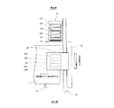
図3は、キャリッジ23の構成とメインタンク26Aとの連結構造を示す斜視図、図4はメインタンク26Aの前面側の構造を示す斜視図である。インク補充供給手段としてのメインタンク26Aは、複数のインクカートリッジ26・・・を脱着可能な箱体で、インクカートリッジ26の脱着を行うための開閉可能な前カバー26Bを備えている(図3では図示を省略してある)。また、キャリッジ23に搭載したサブタンク25には、インク供給チューブ26Cを介してメインタンク26Aからインクを補充供給するようになっている。
FIG. 3 is a perspective view showing the structure of the
サブタンク25は、インクを収容するインク収容部100を形成する容器本体(ケース)101に、インク収容部100の開口を封止する可撓性を有するフィルム状部材102を接着または溶着等で貼り付けたものであり、容器本体101とフィルム状部材102との間にはフィルム状部材102を外方に付勢するためのバネ(図示せず)を介在させ、フィルム状部材102にはバネに対応して膨らみ部を形成してその外面に補強部材104を貼り付け、そしてフィルム状部材102をバネに抗して押圧するための負圧レバー106をフィルム状部材102に対して進退できるようにケース101の側部に対して揺動可能に取り付けてある。
In the
なお図3において、151は負圧ピン、152はスプリング、153は大気開放ピンであり、レバー161を備えた駆動ユニット162を大気開放ピン153の駆動用に配してあり、サブタンク25の負圧レバー106を負圧ピン151でケース101側の図示しないバネに抗して作動させた後に復帰させることで、インク収容部100内に負圧を発生させることができるようになっている。
In FIG. 3, 151 is a negative pressure pin, 152 is a spring, 153 is an air release pin, a
図5は、インクカートリッジ26のケース内に収納する本発明に係る液体収納容器の一例としてのインク収納袋80を模式的に示す平面図(A)とその使用形態を示す断面図(B)である。図示のインク収納袋80は、例えばアルミフィルムを基材として内側にポリエチレンフィルムをラミネートし、外側にナイロンフィルムやポリエチレンフィルム等をラミネートして可撓かつ扁平で長方形状に形成したもので、潰れやすく、内部のインク等の液体の残量に応じて容積が縮小していくものとなっている。そして、短手となる両縁それぞれにインク供給部81と空気導入部82が設けてあり、それらを内部へ連通させる部分以外は熱溶着等によって閉じ、インクを密封してある。インク供給部81と空気導入部82にはそれぞれシール機構を備えるが、図示及び詳細な説明は省略する。
FIG. 5 is a plan view (A) schematically showing an
なおインク収納袋80の内部にインクの残量を検知する手段やインクを押し出すための手段等の公知の手段を収納する構成としても良いが、いずれも一対のインク供給部81、81に対応させて設けるようにすることが好ましい。インクの残量を検知する手段を設ける場合には、残量が僅かになってインク収納袋80が潰れてしまう前に検知できるものであることが好ましい。
It should be noted that known means such as a means for detecting the remaining amount of ink and a means for pushing out the ink may be housed inside the
図5(B)に示すように、図5(A)に示したインク収納袋80を収納するためのインクカートリッジ26のケース26a〜26dのうち、ケース26dはインクを収納した状態、すなわちインク供給部81と空気導入部82を1個ずつだけ有し、折り曲げ使用しない他の色(本実施例ではBk以外の色)用のインク袋8を収納する他のケース26a〜26cよりも広幅のものとなっている。
As shown in FIG. 5B , among the
なおインク供給部81は、インク袋8、81をインクカートリッジ26のケース26a〜26dのいずれかに収納してカートリッジ装着部26Aに装着するときに、カートリッジ装着部26A側に設けてある供給針(図示せず)に対向し、供給針がインク供給部81内の図示しないシール機構を突き破り、インク供給部81内のインク流出路をカートリッジ装着部26A側のインク供給チューブ26Cに連通させる。供給針その他のカートリッジ装着部26A側の機構については公知のものを用いればよいので図示及び説明は省略する。
The
既述のように本実施例ではBkインクを吐出する二つの液滴吐出ヘッド24k1、24k2を備えるので、それら液滴吐出ヘッド24k1、24k2に対して一つのインク収納袋80の二つのインク供給部81、81からそれぞれ個別にBkインクを供給する。すなわち一つのインクカートリッジ26で複数のインクヘッドにインクを送液することが可能になる。
As described above, the present embodiment includes the two droplet discharge heads 24k1 and 24k2 for discharging Bk ink, and therefore, the two ink supply portions of one
ところで周知のように、インクジェットヘッドを備えた画像形成装置等においては、液体のインクを供給するに当たっては適度な負圧を与えることによって望ましいメニスカスを形成させ、適正なインク吐出量として高品質の印刷を可能としているが、負圧が弱すぎると記録ヘッドからのインクのボタ落ちが生じてインクが飛散し、逆に負圧が強すぎるとインクが出にくくなったり、印字のかすれや印刷不能が生じたりする。この現象は、可撓性を有する素材からなる袋状のインク容器等で起こりやすい。そこでこの逆流防止については従来種々の対応策が案出され、採用されている。 As is well known, in an image forming apparatus equipped with an ink jet head, a desired meniscus is formed by applying an appropriate negative pressure when supplying liquid ink, and high-quality printing is performed as an appropriate ink discharge amount. However, if the negative pressure is too weak, ink drops from the recording head and the ink scatters.On the other hand, if the negative pressure is too strong, it is difficult for the ink to come out, and printing may be blurred or unprintable. It occurs. This phenomenon is likely to occur in a bag-like ink container made of a flexible material. So this anti-reflux is devised conventional various countermeasures that are adopted.
本実施例の場合、少なくとも二つのインク供給部81、81での相互の影響を無くし、あるいはできるだけ小さくする必要がある。一対のインク供給部81、81を吸出し口とし、そこから吸出し装置(例えばポンプ等)によって液体であるインクを吸い出す構成とすると、片側部分(以下、インク収納室8A)から吸い出している際に残量が少なくなってくると、他側の部分(以下、インク収納室8B)と折り曲げ部分を介して内部的には連通しているため、インク収納袋80内の負圧が全体として大きくなり、インクの吸い出しを行っていないインク収納室8Bではサブタンク25側からのインクの逆流が発生してしまう可能性が考えられるためである。ところが、本願発明者等の行った実験では、袋状のインク容器、すなわち本実施例のインク収納袋80のようなものを折り曲げて使用するだけで負圧変化によるインクの逆流防止にも非常に有効であった。
In the case of this embodiment, it is necessary to eliminate the influence of at least two
また、機器のレイアウトを考慮すると、小型化のためには二つの吸出し口、すなわちインク供給部81、81は互いに近接していることが望ましく、その一方で二つのインク供給部81、81間の流路を長くとることも望ましい。すなわち、流路が細く長くなれば流路抵抗が増大し、吸出し口であるインク供給部81、81が互いの影響を受けにくくなるためである。上述の実施例では、インク収納袋80を折り曲げることによってこれを達成しているものと考えられる。
In consideration of the layout of the device, it is desirable that the two suction ports, that is, the
なおインク収納袋80は、既述のように内部の液体の残量に応じて容積が縮小していくものが好ましく、換言すれば残量が大きい時は十分に容積が大きく、残量が僅少になった時には急激に潰れて二つのインク収納室8A、8B間の流路抵抗(周知のように断面積の2乗に反比例し、長さに比例する)が大きくなるものが好ましい。またインク供給部81を設ける位置は、図示の例のように袋の短手方向の縁の中央部分にしなければならないというものではなく、インクの残量が大きいときには流路抵抗が小さく、インクの残量が小さくなると流路抵抗が大きくなるという条件を満たし得る箇所があれば、その部位とすることが好ましい。
The
図6は、本発明に係る液体収納容器との比較のための参考例としてのインク収納袋を示す断面図である。この例は、上述のような流路抵抗について考慮し、二つのインク供給部81、81の間の流路(すなわち袋の内部空間)を適宜の仕切り部材83によって仕切ることによってインク収納袋80内に二つの収納室81A、81Bを形成したものである。この例では、インク供給部81、81の直接的な距離は近く、両部の間の流路は長くなり、そしてインクを吸い出されていく側の収納室がインクの残量が僅かになるとつぶれて内部の流路抵抗が大きくなり(例えば図の例では、R1<R2<R3<R4<R5:Rは流路抵抗)、他側の収納室に対して影響を及ぼしにくくなるようにすることができる。
FIG. 6 is a cross-sectional view showing an ink storage bag as a reference example for comparison with the liquid storage container according to the present invention . In this example, the flow path resistance as described above is considered, and the flow path (that is, the internal space of the bag) between the two
図7は本発明に係る液体収納容器のさらに他の参考例としてのインク収納袋を示す断面図である。この例は、略心臓形のインク収納袋80を用い、二つのインク供給部81、81間のくびれ部分(図中矢印Kで示す部分)の寸法、形状等を適宜調節することにより、折り曲げた例の場合と同様にインク供給部81、81が互いの影響を受けにくくなるようにすることができる。
FIG. 7 is a sectional view showing an ink storage bag as still another reference example of the liquid storage container according to the present invention . This example, using the ink retract and
図8は本発明に係る液体収納容器のまたさらに他の参考例としてのインク収納袋を示す断面図である。この例は、可撓性の袋ではない素材を用いた場合等に有効なもので、二つのインク供給部81、81をインク収納袋80のできるだけ離れた位置に設け、袋内部に複数の仕切り部材83・・・を設けてカスケード状の流路を形成し、インク供給部81、81が互いの影響を受けにくくなるようにしたものである。
FIG. 8 is a cross-sectional view showing an ink storage bag as still another reference example of the liquid storage container according to the present invention . This example is effective when a material that is not a flexible bag is used. The two
なお以上説明してきた実施例は、メインタンク、サブタンクを用いるシステムのみであるが、本発明はこれに限定されず、記録ヘッドに直接インクタンクを搭載するタイプのものにも適用できる。 Examples Note has been described above, the main tank, but only system using the sub tank, the present invention is not limited thereto, Ru can be applied to a type for mounting the ink tank directly to the recording head.
1:装置本体
2:画像形成部
3:副走査搬送部
4:給紙部
5:用紙
6:排紙搬送部
7:排紙トレイ
8:インク収納袋
9:印字ユニット
10:圧板
11:画像読取部(スキャナ部)
12:コンタクトガラス
13:照明光源
14:ミラー
15:走査光学系
16、17:ミラー
18:走査光学系
19:レンズ
20:画像読み取り素子
21:キャリッジガイド
23:キャリッジ
24:記録ヘッド
24k1、24k2、24c、24m、24y:液滴吐出ヘッド
26:インクカートリッジ
26A:メインタンク
26B:前カバー
26C:インク供給チューブ
26D:ケース
27:維持回復機構(維持回復ユニット)
28a、28b、28c、28d:キャップ部材
29:ワイパーブレード
30:空吐出受け
31:印写部搬送ローラ
32:押えローラ
33:印写部搬送ローラ対
34:印写部搬送ローラ対
35:用紙ガイド板
41:給紙カセット
42:給紙コロ
43:フリクションパッド
61:排紙搬送ローラ対
62:排紙ローラ
63:排紙搬送ローラ対
64:排出ローラ
80:インク収納袋
81:インク供給部
81A、81B:インク収納室
82:空気導入部
83:仕切り部材
100:インク収容部
101:容器本体(ケース)
102:フィルム状部材
104:補強部材
106:負圧レバー
151:負圧ピン
152:スプリング
153:大気開放ピン
161:レバー
162:駆動ユニット
1: Device body
2: Image forming unit
3: Sub-scan transport unit
4: Paper feeder
5: Paper
6: Discharge transport section
7: Output tray
8: Ink storage bag
9: Printing unit
10: Pressure plate
11: Image reading unit (scanner unit)
12: Contact glass
13: Illumination light source
14: Mirror
15: Scanning optical system
16, 17: Mirror
18: Scanning optical system
19: Lens
20: Image reading element
21: Carriage guide
23: Carriage
24: Recording head
24k1, 24k2, 24c, 24m, 24y: droplet discharge head
26: Ink cartridge
26A: Main tank
26B: Front cover
26C: Ink supply tube
26D: Case
27: Maintenance and recovery mechanism (Maintenance and recovery unit)
28a, 28b, 28c, 28d: cap members
29: Wiper blade
30: Empty discharge receptacle
31: Printing unit conveyance roller
32: Presser roller
33: Printing section conveyance roller pair
34: Pair of transfer roller for printing unit
35: Paper guide plate
41: Paper cassette
42: Feed roller
43: Friction pad
61: Paper delivery roller pair
62: Paper discharge roller
63: Paper delivery roller pair
64: discharge roller
80: Ink storage bag
81: Ink supply unit
81A, 81B: ink storage chamber
82: Air introduction part
83: Partition member
100: Ink container
101: Container body (case)
102: Film-like member
104: Reinforcing member
106: Negative pressure lever
151: Negative pressure pin
152: Spring
153: Atmospheric release pin
161: Lever
162: Drive unit
Claims (4)
二つ折りした状態で前記2つの吸出し口間における内部流路長がこれら2つの吸出し口間の距離より長くなる形状としてなることを特徴とするインク袋。 Flexible and an ink bag that is formed in a flat rectangular shape, the suction port of the housing ink two possess, to come close to each suction port of the two ink to clamshell, a transverse The suction port is arranged on each edge,
The ink bag internal flow path length, wherein Rukoto such as to become longer shape than the distance between the two suction port between the two suction port in two-folded state.
An image forming apparatus using the ink jet recording apparatus according to claim 3 .
Priority Applications (1)
| Application Number | Priority Date | Filing Date | Title |
|---|---|---|---|
| JP2004137071A JP4410023B2 (en) | 2004-05-06 | 2004-05-06 | Ink bag, ink cartridge, ink jet recording apparatus, and image forming apparatus |
Applications Claiming Priority (1)
| Application Number | Priority Date | Filing Date | Title |
|---|---|---|---|
| JP2004137071A JP4410023B2 (en) | 2004-05-06 | 2004-05-06 | Ink bag, ink cartridge, ink jet recording apparatus, and image forming apparatus |
Publications (2)
| Publication Number | Publication Date |
|---|---|
| JP2005319587A JP2005319587A (en) | 2005-11-17 |
| JP4410023B2 true JP4410023B2 (en) | 2010-02-03 |
Family
ID=35467228
Family Applications (1)
| Application Number | Title | Priority Date | Filing Date |
|---|---|---|---|
| JP2004137071A Expired - Fee Related JP4410023B2 (en) | 2004-05-06 | 2004-05-06 | Ink bag, ink cartridge, ink jet recording apparatus, and image forming apparatus |
Country Status (1)
| Country | Link |
|---|---|
| JP (1) | JP4410023B2 (en) |
Cited By (2)
| Publication number | Priority date | Publication date | Assignee | Title |
|---|---|---|---|---|
| US10000063B2 (en) | 2015-12-21 | 2018-06-19 | Seiko Epson Corporation | Liquid containing member |
| US10220626B2 (en) | 2016-08-12 | 2019-03-05 | Seiko Epson Corporation | Liquid container |
Families Citing this family (2)
| Publication number | Priority date | Publication date | Assignee | Title |
|---|---|---|---|---|
| JP2007268765A (en) * | 2006-03-30 | 2007-10-18 | Noritsu Koki Co Ltd | Inkjet printer |
| JP6891481B2 (en) * | 2016-12-21 | 2021-06-18 | セイコーエプソン株式会社 | Liquid injection device |
-
2004
- 2004-05-06 JP JP2004137071A patent/JP4410023B2/en not_active Expired - Fee Related
Cited By (3)
| Publication number | Priority date | Publication date | Assignee | Title |
|---|---|---|---|---|
| US10000063B2 (en) | 2015-12-21 | 2018-06-19 | Seiko Epson Corporation | Liquid containing member |
| US10173431B2 (en) | 2015-12-21 | 2019-01-08 | Seiko Epson Corporation | Liquid containing member |
| US10220626B2 (en) | 2016-08-12 | 2019-03-05 | Seiko Epson Corporation | Liquid container |
Also Published As
| Publication number | Publication date |
|---|---|
| JP2005319587A (en) | 2005-11-17 |
Similar Documents
| Publication | Publication Date | Title |
|---|---|---|
| JP4841349B2 (en) | Liquid ejection head unit and image forming apparatus | |
| US20100277555A1 (en) | Ink Cartridge And Image Forming Apparatus Employing The Ink Cartridge | |
| US8882241B2 (en) | Liquid-jet head and liquid-jet head device | |
| US8388119B2 (en) | Liquid container and image forming apparatus including the liquid container | |
| US8662634B2 (en) | Image forming apparatus including liquid ejection head for ejecting liquid droplets | |
| JP4155879B2 (en) | Liquid container, liquid supply apparatus, and image forming apparatus | |
| JP4680050B2 (en) | Image forming apparatus | |
| JP5516248B2 (en) | Liquid container and image forming apparatus | |
| US8336998B2 (en) | Image forming apparatus | |
| JP2005262521A (en) | Image forming device | |
| JP4671881B2 (en) | Liquid container and image forming apparatus | |
| US7465043B2 (en) | Liquid distribution unit, ink-jet recording apparatus and image forming apparatus | |
| JP4410023B2 (en) | Ink bag, ink cartridge, ink jet recording apparatus, and image forming apparatus | |
| JP2007130979A (en) | Image forming device | |
| JP4662841B2 (en) | Recording liquid storage bag, recording liquid storage container, image forming apparatus, and recording liquid storage bag manufacturing method | |
| JP2007136871A (en) | Image forming device | |
| JP2015112847A (en) | Liquid supply device and image formation device including the same | |
| JP4688189B2 (en) | Liquid supply apparatus and image forming apparatus | |
| JP2006237945A (en) | Image forming apparatus | |
| JP2003094692A (en) | Ink jet recording device | |
| JP5201078B2 (en) | Recording agent container and image forming apparatus | |
| JP2007062247A (en) | Recording liquid cartridge and image forming device | |
| JP4671884B2 (en) | Image forming apparatus | |
| JP2010253834A (en) | Waste liquid housing container and image forming apparatus | |
| JP2010208098A (en) | Liquid container and image forming apparatus |
Legal Events
| Date | Code | Title | Description |
|---|---|---|---|
| A621 | Written request for application examination |
Free format text: JAPANESE INTERMEDIATE CODE: A621 Effective date: 20060721 |
|
| A977 | Report on retrieval |
Free format text: JAPANESE INTERMEDIATE CODE: A971007 Effective date: 20090723 |
|
| A131 | Notification of reasons for refusal |
Free format text: JAPANESE INTERMEDIATE CODE: A131 Effective date: 20090811 |
|
| A521 | Written amendment |
Free format text: JAPANESE INTERMEDIATE CODE: A523 Effective date: 20091007 |
|
| TRDD | Decision of grant or rejection written | ||
| A01 | Written decision to grant a patent or to grant a registration (utility model) |
Free format text: JAPANESE INTERMEDIATE CODE: A01 Effective date: 20091028 |
|
| A01 | Written decision to grant a patent or to grant a registration (utility model) |
Free format text: JAPANESE INTERMEDIATE CODE: A01 |
|
| A61 | First payment of annual fees (during grant procedure) |
Free format text: JAPANESE INTERMEDIATE CODE: A61 Effective date: 20091112 |
|
| R150 | Certificate of patent (=grant) or registration of utility model |
Free format text: JAPANESE INTERMEDIATE CODE: R150 |
|
| FPAY | Renewal fee payment (prs date is renewal date of database) |
Free format text: PAYMENT UNTIL: 20121120 Year of fee payment: 3 |
|
| FPAY | Renewal fee payment (prs date is renewal date of database) |
Free format text: PAYMENT UNTIL: 20131120 Year of fee payment: 4 |
|
| LAPS | Cancellation because of no payment of annual fees |