EP3184203B1 - Filling chamber for a diecasting machine - Google Patents
Filling chamber for a diecasting machine Download PDFInfo
- Publication number
- EP3184203B1 EP3184203B1 EP16002518.5A EP16002518A EP3184203B1 EP 3184203 B1 EP3184203 B1 EP 3184203B1 EP 16002518 A EP16002518 A EP 16002518A EP 3184203 B1 EP3184203 B1 EP 3184203B1
- Authority
- EP
- European Patent Office
- Prior art keywords
- molybdenum
- filling chamber
- insert
- molybdenum alloy
- alloy
- Prior art date
- Legal status (The legal status is an assumption and is not a legal conclusion. Google has not performed a legal analysis and makes no representation as to the accuracy of the status listed.)
- Active
Links
- 238000004512 die casting Methods 0.000 title claims description 11
- ZOKXTWBITQBERF-UHFFFAOYSA-N Molybdenum Chemical compound [Mo] ZOKXTWBITQBERF-UHFFFAOYSA-N 0.000 claims description 48
- 229910052750 molybdenum Inorganic materials 0.000 claims description 48
- 239000011733 molybdenum Substances 0.000 claims description 48
- 229910001182 Mo alloy Inorganic materials 0.000 claims description 39
- 239000000463 material Substances 0.000 claims description 18
- 229910052751 metal Inorganic materials 0.000 claims description 10
- 239000002184 metal Substances 0.000 claims description 10
- 238000005266 casting Methods 0.000 claims description 9
- 239000007788 liquid Substances 0.000 claims description 4
- 229910000831 Steel Inorganic materials 0.000 description 6
- 239000010959 steel Substances 0.000 description 6
- 229910021193 La 2 O 3 Inorganic materials 0.000 description 4
- 229910052802 copper Inorganic materials 0.000 description 3
- 239000010949 copper Substances 0.000 description 3
- 229910052702 rhenium Inorganic materials 0.000 description 3
- 239000010936 titanium Substances 0.000 description 3
- 229910052721 tungsten Inorganic materials 0.000 description 3
- 229910045601 alloy Inorganic materials 0.000 description 2
- 239000000956 alloy Substances 0.000 description 2
- 229910052799 carbon Inorganic materials 0.000 description 2
- 238000001816 cooling Methods 0.000 description 2
- 239000000155 melt Substances 0.000 description 2
- 150000001247 metal acetylides Chemical class 0.000 description 2
- 238000001953 recrystallisation Methods 0.000 description 2
- 229910000838 Al alloy Inorganic materials 0.000 description 1
- 241001239379 Calophysus macropterus Species 0.000 description 1
- OKTJSMMVPCPJKN-UHFFFAOYSA-N Carbon Chemical compound [C] OKTJSMMVPCPJKN-UHFFFAOYSA-N 0.000 description 1
- 229910052684 Cerium Inorganic materials 0.000 description 1
- RYGMFSIKBFXOCR-UHFFFAOYSA-N Copper Chemical compound [Cu] RYGMFSIKBFXOCR-UHFFFAOYSA-N 0.000 description 1
- 229910000640 Fe alloy Inorganic materials 0.000 description 1
- 229910015269 MoCu Inorganic materials 0.000 description 1
- 229910016024 MoTa Inorganic materials 0.000 description 1
- RTAQQCXQSZGOHL-UHFFFAOYSA-N Titanium Chemical compound [Ti] RTAQQCXQSZGOHL-UHFFFAOYSA-N 0.000 description 1
- QCWXUUIWCKQGHC-UHFFFAOYSA-N Zirconium Chemical compound [Zr] QCWXUUIWCKQGHC-UHFFFAOYSA-N 0.000 description 1
- 229910052782 aluminium Inorganic materials 0.000 description 1
- XAGFODPZIPBFFR-UHFFFAOYSA-N aluminium Chemical compound [Al] XAGFODPZIPBFFR-UHFFFAOYSA-N 0.000 description 1
- 230000015572 biosynthetic process Effects 0.000 description 1
- 239000002826 coolant Substances 0.000 description 1
- 238000005260 corrosion Methods 0.000 description 1
- 230000007797 corrosion Effects 0.000 description 1
- 239000013078 crystal Substances 0.000 description 1
- 230000001419 dependent effect Effects 0.000 description 1
- 238000011161 development Methods 0.000 description 1
- 230000018109 developmental process Effects 0.000 description 1
- 230000000694 effects Effects 0.000 description 1
- 229910052735 hafnium Inorganic materials 0.000 description 1
- 230000009931 harmful effect Effects 0.000 description 1
- 239000012943 hotmelt Substances 0.000 description 1
- 238000003780 insertion Methods 0.000 description 1
- 230000037431 insertion Effects 0.000 description 1
- 238000009434 installation Methods 0.000 description 1
- XEEYBQQBJWHFJM-UHFFFAOYSA-N iron Substances [Fe] XEEYBQQBJWHFJM-UHFFFAOYSA-N 0.000 description 1
- 229910052742 iron Inorganic materials 0.000 description 1
- MRELNEQAGSRDBK-UHFFFAOYSA-N lanthanum oxide Inorganic materials [O-2].[O-2].[O-2].[La+3].[La+3] MRELNEQAGSRDBK-UHFFFAOYSA-N 0.000 description 1
- 238000002386 leaching Methods 0.000 description 1
- 238000000034 method Methods 0.000 description 1
- 239000000203 mixture Substances 0.000 description 1
- 229910052758 niobium Inorganic materials 0.000 description 1
- 210000002445 nipple Anatomy 0.000 description 1
- 230000002093 peripheral effect Effects 0.000 description 1
- 230000002035 prolonged effect Effects 0.000 description 1
- 230000001681 protective effect Effects 0.000 description 1
- WUAPFZMCVAUBPE-UHFFFAOYSA-N rhenium atom Chemical compound [Re] WUAPFZMCVAUBPE-UHFFFAOYSA-N 0.000 description 1
- 239000000126 substance Substances 0.000 description 1
- 230000008093 supporting effect Effects 0.000 description 1
- 229910052715 tantalum Inorganic materials 0.000 description 1
- 229910052719 titanium Inorganic materials 0.000 description 1
- 230000007704 transition Effects 0.000 description 1
- RUDFQVOCFDJEEF-UHFFFAOYSA-N yttrium(III) oxide Inorganic materials [O-2].[O-2].[O-2].[Y+3].[Y+3] RUDFQVOCFDJEEF-UHFFFAOYSA-N 0.000 description 1
- 229910052726 zirconium Inorganic materials 0.000 description 1
Images

Classifications
-
- B—PERFORMING OPERATIONS; TRANSPORTING
- B22—CASTING; POWDER METALLURGY
- B22D—CASTING OF METALS; CASTING OF OTHER SUBSTANCES BY THE SAME PROCESSES OR DEVICES
- B22D17/00—Pressure die casting or injection die casting, i.e. casting in which the metal is forced into a mould under high pressure
- B22D17/20—Accessories: Details
- B22D17/2015—Means for forcing the molten metal into the die
- B22D17/2023—Nozzles or shot sleeves
-
- B—PERFORMING OPERATIONS; TRANSPORTING
- B22—CASTING; POWDER METALLURGY
- B22D—CASTING OF METALS; CASTING OF OTHER SUBSTANCES BY THE SAME PROCESSES OR DEVICES
- B22D17/00—Pressure die casting or injection die casting, i.e. casting in which the metal is forced into a mould under high pressure
- B22D17/08—Cold chamber machines, i.e. with unheated press chamber into which molten metal is ladled
- B22D17/10—Cold chamber machines, i.e. with unheated press chamber into which molten metal is ladled with horizontal press motion
Definitions
- the invention relates to a filling chamber for a die casting machine according to the preamble of claim 1.
- the inner surface of the filling chamber of a die casting machine is most affected by wear in the region of the feed opening.
- this always impinges on the inner surface of the filling chamber at the same location below the feed opening.
- washouts in the area below the feed opening, whereby the sliding movement of the pressure piston in the chamber can be hindered and the pressure piston is exposed to greater wear.
- An insert that extends only over the area of the feed opening and that can be rapidly replaced with a new one when worn, provides a quick remedy in the most common cases of wear of the sliding surface for the pressure piston.
- the insert extends from the outer end of the filling chamber to axially within the feed opening and comes into contact at its inner end in a narrow annular region with its peripheral surface with the inner wall of the filling chamber, while at its outer end of a between its outer periphery and the inner wall the filling chamber attacking centering is guided coaxially to the filling chamber.
- a filling chamber for a die casting machine with a supply port for liquid casting material in which in the filling chamber wall in the region opposite to the feed opening a cooling device is provided.
- the cooling device is formed from an insertable from the outside into the Golfschand disc, which is provided with at least one guide channel for a coolant.
- this measure is intended to extend the service life of a filling chamber insert.
- a filling chamber for a die casting machine whose cylindrical inner surface serves as a sliding surface for a pressure piston and which has a feed opening for liquid casting material.
- the filling chamber consists of a base material made of an iron alloy on the inside of which an inner layer of molybdenum or a molybdenum alloy is applied over the entire surface.
- the invention has the object of developing a filling chamber for a die casting machine for longer life.
- the invention includes a filling chamber for a die casting machine, the cylindrical inner surface serving as a sliding surface for a pressure piston and having a feed opening for liquid casting material and a removable cylindrical insert, on the inner surface of the pressure piston slides along and with a radial, with the feed opening of the Filling chamber is provided in the associated opening of the lateral surface.
- the inner surface of the removable insert is at least partially made of molybdenum or a molybdenum alloy.
- the invention is based on the consideration that the greatest wear occurs in a filling chamber in the filling area.
- the reason for the wear are, for example, in die-cast aluminum, low-iron aluminum alloys, the attack the steel of the filling chamber or the exchange socket and can form leaching.
- the commonly used steel is replaced in the filling of the filling chamber by molybdenum or a molybdenum alloy, so that the hot melt initially impinges only on a molybdenum or molybdenum alloy surface.
- Such surfaces are on the one hand thermally stable and resistant to corrosion.
- Pure molybdenum has a linear thermal expansion coefficient of 5.2x10 -6 1 / K at room temperature. These values are considerably lower than those of commercially available steels.
- the molybdenum alloy may be a so-called TZM molybdenum.
- TZM molybdenum is a hardened and particle-reinforced molybdenum based alloy. The formation of a Mo-Ti mixed crystal and finely divided Ti carbides are responsible for the excellent strength properties at temperatures up to 1400 ° C.
- TZM molybdenum is an alloy of 0.50% titanium, 0.08% zirconium and 0.01-0.04% carbon, balance molybdenum. Due to its high strength, TZM molybdenum is particularly suitable for high temperature applications.
- TZM molybdenum has a higher recrystallization temperature, higher strength, hardness and good toughness at room temperature and elevated temperatures than unalloyed molybdenum. In addition, TZM molybdenum has good thermal conductivity and is easy to process.
- molybdenum alloys may be suitable: Material designation Chemical composition [in% by weight] MHC 1.2% Hf, 0.05-0.12% C, balance Mo Mon-lanthanum oxide ML 0.3% La 2 O 3 , balance Mo MLR (recrystallized) 0.7% La 2 O 3 , balance Mo MLS (low tension) 0.7% La 2 O 3 , balance Mo MolLQ 0.03% La 2 O 3 , balance Mo Mon-yttria MY 0.47% Y 2 O 3, 0.08% Ce 2 O 3 , balance Mo MoRe more5 5% Re, rest Mo MoRe41 41% Re, rest Mo MoW MW20 20% W, balance Mo MW30 30% W, rest Mo MW50 50% W, rest Mo MoCu MoCu30 30% Cu, balance Mo MoCu15 15% Cu, balance Mo MoZrO 2 MZ17 1.7% ZrO 2 , balance Mo monb MoNb10 9.71% Nb, rest Mo MoTa MT11 10.75% Ta, rest Mo monb MoNb10 9.71% Nb, rest Mo Mo
- the molybdenum alloy MHC contains carbides as in TZM, which positively influence the mechanical properties.
- admixtures in the form of oxides increase the recrystallization temperature and creep resistance of molybdenum.
- Rhenium in molybdenum ensures better ductility.
- copper increases the thermal conductivity and only slightly changes the thermal expansion coefficient.
- the removable insert may be constructed of a metallic sheath and an inner sleeve of molybdenum or a molybdenum alloy.
- the socket and the protective device are to be regarded as a connected part, which can be mounted as an insert in a filling chamber and also replaced again.
- a sleeve-like protection device for the sleeve made of molybdenum or a molybdenum alloy is arranged by the sheath.
- This protection device allows a nondestructive assembly and disassembly of the socket.
- the metallic sheath of the insert may preferably consist of a steel, which in practice has only slight or no wear and can thus be used for several bushes.
- the preferred geometry of the sheath corresponds to a hollow cylinder, in the inner circumferential surface of the sleeve made of molybdenum or a molybdenum alloy is introduced.
- the outer surface of the sleeve is completely enclosed by the sheath and thereby supported.
- the outer surface of the casing itself comes into contact with the inner surface of the filling chamber.
- the filling opening is correspondingly recessed for the melt, both in the casing and in the bush made of molybdenum or a molybdenum alloy, so that melt can be introduced into the interior of the filling chamber via the filling chamber opening when the system is operated.
- the cylinder-like casing and the sleeve made of molybdenum or a molybdenum alloy are made to fit, ie that the metallic casing of the insert in the axial direction has the same length as the bush made of molybdenum or a molybdenum alloy.
- both Bushes are identical to two sleeves which are precisely pushed into one another and terminate flush with each other in the axial direction, and both have a recess for filling in the melt.
- it can also be carried out axially slightly longer and at least one side with flange surfaces, the metallic shell, with which contacts an end face of the inner sleeve of molybdenum or a molybdenum alloy.
- the bush made of molybdenum or a molybdenum alloy can be made in one piece or in several pieces. With multi-piece bushings occurring during operation thermally induced stresses in the material can be countered.
- sockets can also be composed of two half-shells or even of several segments. Here it is important that the metallic sheath takes over a supporting effect, which holds the individual parts of the sleeve made of molybdenum or a molybdenum alloy.
- the inner sleeve made of molybdenum or a molybdenum alloy can be constructed of several segments.
- the sides of the segments can also be chamfered in order to avoid edge breakouts.
- the surface of the bush largely remains as a sliding surface for the pressure piston.
- the recesses or cavities, which arise through a chamfer or a gap also some melt can penetrate.
- the amount is so small that no harmful effects on the surrounding metal are to be feared.
- a gap filled with die-casting material can also further stabilize the segments and also contribute to a reduction in stress.
- the metallic sheath of the insert a compressive stress on the bush made of molybdenum or a Molybdenum alloy exercises.
- this radial bias can be a tensile stress as an undesirable state of stress in the material compensate both in one-piece sockets as well as constructed from several segments sockets.
- the stress state in the material should at least be below the characteristic values for the tensile stress which are still acceptable for the respective material.
- the metallic sheath of the insert can exert a compressive stress on the bush made of molybdenum or a molybdenum alloy, even at the operating temperature.
- sufficient precautions can be taken even at elevated temperature and as a result of the pressure surges during the pressure casting process that the bushing material has the longest possible service life without being damaged.
- the metallic sheath of the insert may have an axial slot.
- the sheath By choosing the inner diameter of the sheath slightly smaller than the outer diameter of the bush, the sheath can be slightly widened by the axial slot and pushed over the bushing. By widening again creates a radially inward bias by the elastic properties of the metal used.
- the axial slot can also be used to prevent rotation of the entire insert by at least a part of the resulting through the slot opening cooperates with an existing on the Guschand guide nipple or other bulge.
- the metallic sheath of the insert on the sleeve made of molybdenum or a molybdenum alloy overlap the end face and form a uniform cylindrical surface with the inner surface of the sleeve.
- This overlap forms a uniform plane for the pressure piston Sliding surface and the socket is securely fixed in the axial direction.
- the metallic sheathing frontally have a retaining ring which fixes the bush made of molybdenum or a molybdenum alloy.
- the retaining ring is firmly bolted, for example, with the rest of the sheath.
- the removable insert with its inner surface can form only part of the sliding surface for the pressure piston in the region of the feed opening of the filling chamber. In most cases, it is only necessary to set up a protection in the filling zone, since there the hot molten metal meets the filling chamber inner wall first.
- the removable insert may extend from the outer end of the filling chamber to axially within the feed opening. In this part of the plant, the material is exposed to special thermal and corrosive loads.
- the removable insert can be made entirely of molybdenum or a molybdenum alloy.
- the removable insert can have the same geometry as an existing exchange socket.
- it is nevertheless advantageous to simply swap a steel bushing with a molybdenum or molybdenum alloy bush. In this case usually no further adjustments in the geometric design must be carried out.
- the removable insert can a metallic sheath and an inner thin layer of molybdenum or a molybdenum alloy.
- a suitable thin layer may be applied to the inside of the casing, which originally has a slightly larger inner diameter than the rest of the filling chamber. Overall, then the inner diameter of the surface with the layer is in turn aligned with the inner diameter of the rest of the filling chamber.
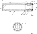
- Fig. 1 schematically shows a longitudinal section through a filling chamber 1 with insert 10 and the feed opening 3 as a filling area for casting material.
- the insert 10 has a cylindrical shape and extends from the outer right end of the filling chamber 1 to within a feed opening 3 in the filling chamber 1 in the coaxial direction.
- the filling chamber 1 is a hollow cylindrical body with a front portion 5, whose inner diameter corresponds to the diameter of the pressure piston, wherein the cylindrical inner surface 2 as a sliding surface for the in Fig. 1 not shown further pressure piston is used.
- At this front Area 5 is followed by a rear area 6, in which the feed opening 3 for the casting material is arranged and which serves to receive the insert 10.
- the rear portion 6 has a larger inner diameter than the front portion 5.
- the inner diameter of the rear portion 6 is designed so that the insert 10 is held securely and can still be removed with simple means.
- a clamping ring 4 is releasably secured, which is pressed against the insert 10 to fix its position inside the filling chamber 1.
- the clamping ring 4 may conveniently be fastened by means of a quick release to the filling chamber 1.
- the clamping ring 4 has a central recess, through which the pressure piston can be guided into the filling chamber 1.
- the removable insert 10 is constructed of a metallic sheath 20 and an inner sleeve of molybdenum or a molybdenum alloy 30.
- the metallic sheathing 20 of the insert 10 engages on the socket made of molybdenum or a molybdenum alloy 30 on the front side and forms with the inner surface 31 of the bushing 30 a uniform cylindrical surface. In this way, the holding force for the fixation of the insert 10 is exerted by the end face of the clamping ring 4 on the metallic shell 20.
- the metallic shell is closed at the end by a retaining ring 25 which fixes the bush made of molybdenum or a molybdenum alloy.
- Fig. 2 schematically shows a view of the end facing away from a mold a filling chamber 1.
- the clamping ring 4 is chamfered at the central recess to form an inclined guide plane for the pressure piston.
- Fig. 3 schematically shows a side view of an insert 10.
- the insert 10 has adjacent to the feed opening 3 from Fig. 1 for the molten metal of the filling chamber 1 has an opening 11 of the lateral surface, which has a slightly larger diameter than the tapered feed opening.
- Fig. 4 schematically shows a longitudinal section through an insert 10 viewed from below, in which the opening 11 can be seen as a rectangular section.
- the insert 10 has an overall uniform inner diameter, wherein the inner surface 31 of the molybdenum or molybdenum alloy bushing and the inner surface of the overlying portion of the casing with the cylindrical inner surface 2 of the filling chamber 1 from Fig. 1 exactly aligned and together with this forms the sliding surface for a pressure piston.
- the outer diameter of the insert 10 is also constant over wide areas. Only at the front end of the transition from the end face to the outer shell of the insert 10 is chamfered to facilitate the insertion of the insert 10 into the filling chamber 1. In addition, the outer diameter of the insert 10 is reduced at the outer end to make room for the arrangement of the clamping ring 4, as in Fig. 1 is shown.
- Fig. 5 schematically shows an oblique view of an insert 10 suitable for mounting in the filling chamber.
Landscapes
- Engineering & Computer Science (AREA)
- Mechanical Engineering (AREA)
- Pistons, Piston Rings, And Cylinders (AREA)
Description
Die Erfindung betrifft eine Füllkammer für eine Druckgießmaschine gemäß dem Oberbegriff des Anspruchs 1.The invention relates to a filling chamber for a die casting machine according to the preamble of
Die Innenfläche der Füllkammer einer Druckgießmaschine ist im Bereich der Zuführöffnung am meisten vom Verschleiß betroffen. Durch das maschinelle Einfüllen von heißem Gießmaterial durch die Zuführöffnung trifft dieses stets an der gleichen Stelle unterhalb der Zuführöffnung auf der Innenfläche der Füllkammer auf. Nach längerem Einsatz der Füllkammer können sich dadurch Auswaschungen im Bereich unterhalb der Zuführöffnung ergeben, wodurch die Gleitbewegung des Druckkolbens in der Kammer behindert werden kann und der Druckkolben einem größeren Verschleiß ausgesetzt ist. So ist aus der Druckschrift
Des Weiteren ist aus der Druckschrift
Zudem ist aus der Druckschrift
Der Erfindung liegt die Aufgabe zugrunde, eine Füllkammer für eine Druckgießmaschine für längere Standzeiten weiterzubilden.The invention has the object of developing a filling chamber for a die casting machine for longer life.
Die Erfindung wird durch die Merkmale des Anspruchs 1 wiedergegeben. Die weiteren rückbezogenen Ansprüche betreffen vorteilhafte Aus- und Weiterbildungen der Erfindung.The invention is represented by the features of
Die Erfindung schließt eine Füllkammer für eine Druckgießmaschine ein, deren zylindrische Innenfläche als Gleitfläche für einen Druckkolben dient und die eine Zuführöffnung für flüssiges Gießmaterial sowie einen entnehmbaren zylindrischen Einsatz aufweist, an dessen Innenfläche der Druckkolben entlang gleitet und der mit einer radialen, mit der Zuführöffnung der Füllkammer in Verbindung stehenden Öffnung der Mantelfläche versehen ist. Erfindungsgemäß besteht die Innenfläche des entnehmbaren Einsatzes zumindest zum Teil aus Molybdän oder einer Molybdänlegierung.The invention includes a filling chamber for a die casting machine, the cylindrical inner surface serving as a sliding surface for a pressure piston and having a feed opening for liquid casting material and a removable cylindrical insert, on the inner surface of the pressure piston slides along and with a radial, with the feed opening of the Filling chamber is provided in the associated opening of the lateral surface. According to the invention, the inner surface of the removable insert is at least partially made of molybdenum or a molybdenum alloy.
Die Erfindung geht dabei von der Überlegung aus, dass der größte Verschleiß in einer Füllkammer im Einfüllbereich vorkommt. Der Grund für den Verschleiß sind, beispielsweise beim Aluminium-Druckguss, eisenarme Aluminiumlegierungen, die den Stahl der Füllkammer bzw. der Wechselbuchse angreifen und Auswaschungen bilden können. Um diesen Effekt zu umgehen wird der üblicherweise verwendete Stahl im Einfüllbereich der Füllkammer durch Molybdän oder eine Molybdänlegierung ausgetauscht, so dass die heiße Schmelze zunächst nur auf eine Molybdän- oder Molybdänlegierungs-Oberfläche auftrifft. Derartige Oberflächen sind einerseits thermisch belastbar und gegenüber Korrosionseinflüssen resistent.The invention is based on the consideration that the greatest wear occurs in a filling chamber in the filling area. The reason for the wear are, for example, in die-cast aluminum, low-iron aluminum alloys, the attack the steel of the filling chamber or the exchange socket and can form leaching. To circumvent this effect, the commonly used steel is replaced in the filling of the filling chamber by molybdenum or a molybdenum alloy, so that the hot melt initially impinges only on a molybdenum or molybdenum alloy surface. Such surfaces are on the one hand thermally stable and resistant to corrosion.
Reines Molybdän weist einen linearen thermischen Ausdehnungskoeffizient von 5,2x10⁻⁶ 1/K bei Raumtemperatur auf. Diese Werte liegen wesentlich unterhalb dem von handelsüblichen Stählen.Pure molybdenum has a linear thermal expansion coefficient of 5.2
Vorteilhafterweise kann die Molybdänlegierung ein sogenanntes TZM-Molybdän sein. TZM-Molybdän ist eine verhärtete und partikelverstärkte Molybdän gegründete Legierung. Die Ausbildung eines Mo-Ti-Mischkristalls und fein verteilte Ti-Carbide sind verantwortlich für die hervorragenden Festigkeitseigenschaften bei Temperaturen bis 1400 °C. TZM-Molybdän ist eine Legierung aus 0,50 % Titan, 0,08 % Zirkonium und 0,01-0,04 % Kohlenstoff, Rest Molybdän. TZM-Molybdän ist aufgrund seiner hohen Festigkeit für Hochtemperaturanwendungen besonders gut geeignet. TZM-Molybdän hat eine höhere Rekristallisationstemperatur, höhere Festigkeit, Härte und gute Zähigkeit bei Raumtemperatur und erhöhten Temperaturen als unlegiertes Molybdän. Darüber hinaus hat TZM-Molybdän eine gute Wärmeleitfähigkeit und ist gut bearbeitbar.Advantageously, the molybdenum alloy may be a so-called TZM molybdenum. TZM molybdenum is a hardened and particle-reinforced molybdenum based alloy. The formation of a Mo-Ti mixed crystal and finely divided Ti carbides are responsible for the excellent strength properties at temperatures up to 1400 ° C. TZM molybdenum is an alloy of 0.50% titanium, 0.08% zirconium and 0.01-0.04% carbon, balance molybdenum. Due to its high strength, TZM molybdenum is particularly suitable for high temperature applications. TZM molybdenum has a higher recrystallization temperature, higher strength, hardness and good toughness at room temperature and elevated temperatures than unalloyed molybdenum. In addition, TZM molybdenum has good thermal conductivity and is easy to process.
Alternativ können auch folgende Molybdänlegierungen geeignet sein:
Bei der Molybdänlegierung MHC sind wie bereits bei TZM Karbide eingebracht, welche die mechanischen Eigenschaften positiv beeinflussen. Beimengungen in Form von Oxiden erhöhen vor allem die Rekristallisationstemperatur und Kriechbeständigkeit des Molybdäns. Rhenium in Molybdän sorgt für eine bessere Duktilität. Wohingegen Kupfer die Wärmeleitfähigkeit erhöht und den thermischen Ausdehnungskoeffizienten nur geringfügig verändert.The molybdenum alloy MHC contains carbides as in TZM, which positively influence the mechanical properties. In particular, admixtures in the form of oxides increase the recrystallization temperature and creep resistance of molybdenum. Rhenium in molybdenum ensures better ductility. Whereas copper increases the thermal conductivity and only slightly changes the thermal expansion coefficient.
In bevorzugter Ausgestaltung der Erfindung kann der entnehmbare Einsatz aus einer metallischen Ummantelung und einer innenliegenden Buchse aus Molybdän oder einer Molybdänlegierung aufgebaut sein. Die Buchse und die Schutzvorrichtung sind als ein zusammengehöriges Teil zu betrachten, welches als Einsatz in eine Füllkammer montiert und auch wieder ausgetauscht werden kann.In a preferred embodiment of the invention, the removable insert may be constructed of a metallic sheath and an inner sleeve of molybdenum or a molybdenum alloy. The socket and the protective device are to be regarded as a connected part, which can be mounted as an insert in a filling chamber and also replaced again.
Da die mechanischen Eigenschaften der Buchse aus Molybdän oder einer Molybdänlegierung bezüglich einer mechanischen Krafteinwirkung beim Ein- und Ausbau kritisch betrachtet werden müssen, wird durch die Ummantelung eine hülsenartige Schutzvorrichtung für die Buchse aus Molybdän oder einer Molybdänlegierung angeordnet. Diese Schutzvorrichtung erlaubt eine zerstörungsfreie Montage und Demontage der Buchse. Die metallische Ummantelung des Einsatzes kann bevorzugt aus einem Stahl bestehen, welcher in der Praxis nur geringfügigen oder gar keinen Verschleiß aufweist und so für mehrere Buchsen verwendet werden kann. Die bevorzugte Geometrie der Ummantelung entspricht einem Hohlzylinder, in dessen innere Mantelfläche die Buchse aus Molybdän oder einer Molybdänlegierung eingebracht ist. Bevorzugt wird die äußere Mantelfläche der Buchse vollständig von der Ummantelung umschlossen und hierdurch gestützt. Die äußere Mantelfläche der Ummantelung selbst tritt mit der Innenoberfläche der Füllkammer in Kontakt. Die Einfüllöffnung ist für die Schmelze sowohl bei der Ummantelung als auch bei der Buchse aus Molybdän oder einer Molybdänlegierung entsprechend ausgespart, so dass über die Füllkammeröffnung Schmelze beim Betreiben der Anlage ins Innere der Füllkammer eingebracht werden kann.Since the mechanical properties of the sleeve made of molybdenum or a molybdenum alloy with respect to a mechanical force during installation and removal must be considered critical, a sleeve-like protection device for the sleeve made of molybdenum or a molybdenum alloy is arranged by the sheath. This protection device allows a nondestructive assembly and disassembly of the socket. The metallic sheath of the insert may preferably consist of a steel, which in practice has only slight or no wear and can thus be used for several bushes. The preferred geometry of the sheath corresponds to a hollow cylinder, in the inner circumferential surface of the sleeve made of molybdenum or a molybdenum alloy is introduced. Preferably, the outer surface of the sleeve is completely enclosed by the sheath and thereby supported. The outer surface of the casing itself comes into contact with the inner surface of the filling chamber. The filling opening is correspondingly recessed for the melt, both in the casing and in the bush made of molybdenum or a molybdenum alloy, so that melt can be introduced into the interior of the filling chamber via the filling chamber opening when the system is operated.
Bevorzugt sind die zylinderartige Ummantelung und die Buchse aus Molybdän oder einer Molybdänlegierung passgenau ausgeführt, d.h. dass die metallische Ummantelung des Einsatzes in axialer Richtung die gleiche Länge wie die Buchse aus Molybdän oder einer Molybdänlegierung aufweist. Mit anderen Worten: Beide Buchsen gleichen zwei passgenau ineinander geschobenen Hülsen, die in axialer Richtung jeweils stirnseitig bündig miteinander abschließen und beide eine Ausnehmung zum Einfüllen der Schmelze aufweisen. Es kann allerdings auch die metallische Ummantelung axial etwas länger und zumindest einseitig mit Flanschflächen ausgeführt sein, mit denen eine Stirnfläche der innenliegenden Buchse aus Molybdän oder einer Molybdänlegierung kontaktiert.Preferably, the cylinder-like casing and the sleeve made of molybdenum or a molybdenum alloy are made to fit, ie that the metallic casing of the insert in the axial direction has the same length as the bush made of molybdenum or a molybdenum alloy. In other words: both Bushes are identical to two sleeves which are precisely pushed into one another and terminate flush with each other in the axial direction, and both have a recess for filling in the melt. However, it can also be carried out axially slightly longer and at least one side with flange surfaces, the metallic shell, with which contacts an end face of the inner sleeve of molybdenum or a molybdenum alloy.
Die Buchse aus Molybdän oder einer Molybdänlegierung kann dabei einstückig oder mehrstückig gefertigt sein. Mit mehrstückig gefertigten Buchsen kann im Betrieb auftretenden thermisch bedingten Spannungen im Material begegnet werden. So können Buchsen auch beispielsweise aus zwei Halbschalen oder auch aus mehreren Segmenten zusammengesetzt sein. Hierbei ist es wichtig, dass die metallische Ummantelung eine stützende Wirkung übernimmt, welche die Einzelteile der Buchse aus Molybdän oder einer Molybdänlegierung zusammenhält.The bush made of molybdenum or a molybdenum alloy can be made in one piece or in several pieces. With multi-piece bushings occurring during operation thermally induced stresses in the material can be countered. For example, sockets can also be composed of two half-shells or even of several segments. Here it is important that the metallic sheath takes over a supporting effect, which holds the individual parts of the sleeve made of molybdenum or a molybdenum alloy.
Vorteilhafterweise kann die innenliegende Buchse aus Molybdän oder einer Molybdänlegierung aus mehreren Segmenten aufgebaut sein. Hierdurch werden im Material Spannungen abgebaut. Um Kantenausbrüche zu vermeiden, können die Seiten der Segmente gegebenenfalls auch angefast sein. Auch bei angefasten Kanten verbleibt die Oberfläche der Buchse weitgehend als Gleitfläche für den Druckkolben erhalten. In die Aussparungen oder Hohlräume, welche durch eine Fase oder einen Spalt entstehen, kann auch etwas Schmelze eindringen. Die Menge ist jedoch so geringfügig, dass keine schädlichen Auswirkungen auf das umgebende Metall zu befürchten sind. Ganz im Gegenteil, ein mit Druckgießmaterial ausgefüllter Spalt kann die Segmente auch weiter stabilisieren und auch zu einem Spannungsabbau beitragen.Advantageously, the inner sleeve made of molybdenum or a molybdenum alloy can be constructed of several segments. As a result, voltages are reduced in the material. If necessary, the sides of the segments can also be chamfered in order to avoid edge breakouts. Even with chamfered edges, the surface of the bush largely remains as a sliding surface for the pressure piston. In the recesses or cavities, which arise through a chamfer or a gap, also some melt can penetrate. However, the amount is so small that no harmful effects on the surrounding metal are to be feared. On the contrary, a gap filled with die-casting material can also further stabilize the segments and also contribute to a reduction in stress.
Demgegenüber ist es auch möglich, dass die metallische Ummantelung des Einsatzes eine Druckspannung auf die Buchse aus Molybdän oder einer Molybdänlegierung ausübt. Mit Hilfe dieser radialen Vorspannung lässt sich eine Zugspannung als unerwünschter Spannungszustand im Material sowohl bei einstückigen Buchsen wie auch bei aus mehreren Segmenten aufgebauten Buchsen kompensieren. Beim Betrieb sollte der Spannungszustand im Material zumindest unter den für das jeweilige Material noch akzeptablen Kennwerten für die Zugspannung liegen.In contrast, it is also possible that the metallic sheath of the insert a compressive stress on the bush made of molybdenum or a Molybdenum alloy exercises. With the help of this radial bias can be a tensile stress as an undesirable state of stress in the material compensate both in one-piece sockets as well as constructed from several segments sockets. During operation, the stress state in the material should at least be below the characteristic values for the tensile stress which are still acceptable for the respective material.
Bei einer vorteilhaften Ausführungsform der Erfindung kann die metallische Ummantelung des Einsatzes auch bei Betriebstemperatur eine Druckspannung auf die Buchse aus Molybdän oder einer Molybdänlegierung ausüben. Hierdurch können auch bei erhöhter Temperatur und infolge der Druckstöße beim Druckgießvorgang ausreichende Vorkehrungen getroffen werden, dass das Buchsenmaterial eine möglichst lange Standzeit aufweist, ohne Schaden zu nehmen.In an advantageous embodiment of the invention, the metallic sheath of the insert can exert a compressive stress on the bush made of molybdenum or a molybdenum alloy, even at the operating temperature. As a result, sufficient precautions can be taken even at elevated temperature and as a result of the pressure surges during the pressure casting process that the bushing material has the longest possible service life without being damaged.
In vorteilhafter Ausgestaltung der Erfindung kann die metallische Ummantelung des Einsatzes einen axialen Schlitz aufweisen. Indem der Innendurchmesser der Ummantelung etwas kleiner als der Außendurchmesser der Buchse gewählt wird, kann die Ummantelung durch den axialen Schlitz etwas aufgeweitet und über die Buchse geschoben werden. Durch das Aufweiten entsteht wiederum eine radial nach innen gerichtete Vorspannung durch die elastischen Eigenschaften des verwendeten Metalls. Der axiale Schlitz kann auch für eine Verdrehsicherung des gesamten Einsatzes genutzt werden, indem zumindest ein Teil der sich durch den Schlitz ergebenden Öffnung mit einem auf der Füllkammerwand vorhandenen Führungsnippel oder einer sonstigen Ausbuchtung zusammenwirkt.In an advantageous embodiment of the invention, the metallic sheath of the insert may have an axial slot. By choosing the inner diameter of the sheath slightly smaller than the outer diameter of the bush, the sheath can be slightly widened by the axial slot and pushed over the bushing. By widening again creates a radially inward bias by the elastic properties of the metal used. The axial slot can also be used to prevent rotation of the entire insert by at least a part of the resulting through the slot opening cooperates with an existing on the Füllkammerwand guide nipple or other bulge.
Vorteilhafterweise kann die metallische Ummantelung des Einsatzes an der Buchse aus Molybdän oder einer Molybdänlegierung stirnseitig übergreifen und mit der Innenfläche der Buchse eine einheitliche zylindrische Fläche bilden. Durch dieses Übergreifen bildet sich für den Druckkolben eine einheitliche ebene Gleitfläche aus und die Buchse wird in axialer Richtung sicher fixiert.Advantageously, the metallic sheath of the insert on the sleeve made of molybdenum or a molybdenum alloy overlap the end face and form a uniform cylindrical surface with the inner surface of the sleeve. This overlap forms a uniform plane for the pressure piston Sliding surface and the socket is securely fixed in the axial direction.
In bevorzugter Ausführungsform der Erfindung kann am inneren Ende des Einsatzes die metallische Ummantelung stirnseitig einen Haltering aufweisen, der die Buchse aus Molybdän oder einer Molybdänlegierung fixiert. Der Haltering wird beispielsweise mit der übrigen Ummantelung fest verschraubt. Mittels dieser wieder lösbaren Verbindung kann im Bedarfsfall eine Buchse leicht ausgewechselt werden.In a preferred embodiment of the invention, at the inner end of the insert, the metallic sheathing frontally have a retaining ring which fixes the bush made of molybdenum or a molybdenum alloy. The retaining ring is firmly bolted, for example, with the rest of the sheath. By means of this re-releasable connection, a socket can be easily replaced if necessary.
In besonders bevorzugter Ausführungsform kann der entnehmbare Einsatz mit seiner Innenfläche nur einen Teil der Gleitfläche für den Druckkolben im Bereich der Zuführöffnung der Füllkammer bilden. Meist ist es nur nötig, in der Einfüllzone einen Schutz einzurichten, da dort die heiße Metallschmelze zuerst auf die Füllkammerinnenwand trifft.In a particularly preferred embodiment, the removable insert with its inner surface can form only part of the sliding surface for the pressure piston in the region of the feed opening of the filling chamber. In most cases, it is only necessary to set up a protection in the filling zone, since there the hot molten metal meets the filling chamber inner wall first.
In weiterer vorteilhafter Ausgestaltung der Erfindung kann sich der entnehmbare Einsatz vom äußeren Ende der Füllkammer bis axial innerhalb der Zuführöffnung erstrecken. In diesem Anlagenteil ist das Material besonderen thermischen und korrosiven Belastungen ausgesetzt.In a further advantageous embodiment of the invention, the removable insert may extend from the outer end of the filling chamber to axially within the feed opening. In this part of the plant, the material is exposed to special thermal and corrosive loads.
Vorteilhafterweise kann der entnehmbare Einsatz vollständig aus Molybdän oder einer Molybdänlegierung bestehen. Es gibt bereits Füllkammern mit Wechselbuchsen aus Stahl, wodurch dann diese Art von Einsatz die gleiche Geometrie wie eine vorhandene Wechselbuchse haben kann. Dadurch ist es bei vorsichtigem Umgang mit dem Material dennoch von Vorteil, eine Stahlbuchse einfach durch eine entsprechende Buchse aus Molybdän oder einer Molybdänlegierung zu tauschen. Hierbei müssen üblicherweise keine weiteren Anpassungen in der geometrischen Auslegung durchgeführt werden.Advantageously, the removable insert can be made entirely of molybdenum or a molybdenum alloy. There are already filling chambers with exchangeable bushes made of steel, whereby then this type of insert can have the same geometry as an existing exchange socket. As a result, when handling the material with care, it is nevertheless advantageous to simply swap a steel bushing with a molybdenum or molybdenum alloy bush. In this case usually no further adjustments in the geometric design must be carried out.
In einer weiteren vorteilhaften Ausgestaltung kann der entnehmbare Einsatz aus einer metallischen Ummantelung und einer innenliegenden dünnen Schicht aus Molybdän oder einer Molybdänlegierung aufgebaut sein. Hierbei kann eine geeignete dünne Schicht auf die Innenseite der Ummantelung aufgebracht sein, welche ursprünglich einen etwas größeren Innendurchmesser als die übrige Füllkammer aufweist. Insgesamt ist dann der Innendurchmesser der Oberfläche mit der Schicht wiederum an den Innendurchmesser der übrigen Füllkammer angeglichen.In a further advantageous embodiment of the removable insert can a metallic sheath and an inner thin layer of molybdenum or a molybdenum alloy. Here, a suitable thin layer may be applied to the inside of the casing, which originally has a slightly larger inner diameter than the rest of the filling chamber. Overall, then the inner diameter of the surface with the layer is in turn aligned with the inner diameter of the rest of the filling chamber.
Ausführungsbeispiele der Erfindung werden anhand der schematischen Zeichnungen näher erläutert.Embodiments of the invention will be explained in more detail with reference to the schematic drawings.
Darin zeigen:
- Fig. 1
- schematisch einen Längsschnitt durch eine Füllkammer mit Einsatz,
- Fig. 2
- schematisch eine Ansicht der einer Gießform abgewandten Stirnseite einer Füllkammer,
- Fig. 3
- schematisch eine Seitenansicht eines Einsatzes,
- Fig. 4
- schematisch einen Längsschnitt durch einen Einsatz, und
- Fig. 5
- schematisch eine Schrägansicht eines Einsatzes.
- Fig. 1
- schematically a longitudinal section through a filling chamber with insert,
- Fig. 2
- 2 is a schematic view of the front side of a filling chamber facing away from a casting mold;
- Fig. 3
- schematically a side view of an insert,
- Fig. 4
- schematically a longitudinal section through an insert, and
- Fig. 5
- schematically an oblique view of an insert.
Einander entsprechende Teile sind in allen Figuren mit denselben Bezugszeichen versehen.Corresponding parts are provided in all figures with the same reference numerals.
An der Stirnseite der Füllkammer 1 ist ein Spannring 4 lösbar befestigt, welcher gegen den Einsatz 10 gepresst wird, um dessen Lage im Inneren der Füllkammer 1 zu fixieren. Dabei kann der Spannring 4 zweckmäßigerweise mittels eines Schnellverschlusses an der Füllkammer 1 befestigbar sein. Dadurch ist ein schnelles Entnehmen und Austauschen des Einsatzes 10 der Füllkammer 1 sichergestellt. Der Spannring 4 weist eine zentrale Ausnehmung auf, durch die der Druckkolben in die Füllkammer 1 geführt werden kann.On the front side of the filling
In
Am inneren Ende des Einsatzes ist die metallische Ummantelung stirnseitig durch einen Haltering 25 abgeschlossen, der die Buchse aus Molybdän oder einer Molybdänlegierung fixiert. Mittels dieser wieder lösbaren Verbindung kann im Bedarfsfall eine Buchse aus Molybdän oder einer Molybdänlegierung mit geringem Aufwand ausgewechselt werden.At the inner end of the insert, the metallic shell is closed at the end by a retaining
Der Außendurchmesser des Einsatzes 10 ist über weite Bereiche ebenfalls konstant. Lediglich am vorderen Ende ist der Übergang von der Stirnfläche zum Außenmantel des Einsatzes 10 abgeschrägt, um das Einführen des Einsatzes 10 in die Füllkammer 1 zu erleichtern. Außerdem ist der Außendurchmesser des Einsatzes 10 am äußeren Ende verringert, um Platz zu schaffen für die Anordnung des Spannringes 4, wie in
- 11
- Füllkammerfilling chamber
- 22
- zylindrische Innenflächecylindrical inner surface
- 33
- Zuführöffnungfeed
- 44
- Spannringclamping ring
- 55
- vorderer Bereichfront area
- 66
- hinterer Bereichthe backstage area
- 1010
- Einsatzcommitment
- 1111
- Öffnung der MantelflächeOpening of the lateral surface
- 2020
- metallische Ummantelungmetallic sheath
- 2525
- Halteringretaining ring
- 3030
- Buchse aus Molybdän oder einer MolybdänlegierungBush made of molybdenum or a molybdenum alloy
- 3131
- Innenfläche der BuchseInner surface of the bush
Claims (10)
- Filling chamber (1) for a diecasting machine, the cylindrical inner surface (2) of which is used as a sliding surface for a piston and which comprises a supply opening (3) for liquid casting material and comprises a removable cylindrical insert (10) along the inner surface of which the piston slides and which is provided with a radial opening in the lateral surface (11) that is connected to the supply opening (3) of the filling chamber (1),
characterized in that
the inner surface of the removable insert (10) consists at least in part of molybdenum or a molybdenum alloy, the removable insert (10) being made from a metal casing (20) and an internal liner made of molybdenum or a molybdenum alloy (30). - Filling chamber (1) according to claim 1, characterized in that the molybdenum alloy is TZM molybdenum.
- Filling chamber (1) according to either claim 1 or claim 2, characterized in that the internal liner is made from molybdenum or a molybdenum alloy (30) composed of a plurality of segments.
- Filling chamber (1) according to any one of claims 1 to 3, characterized in that the metal casing (20) of the insert (10) exerts a compressive stress on the liner made of molybdenum or a molybdenum alloy (30).
- Filling chamber (1) according to claim 4, characterized in that, even at operating temperature, the metal casing (20) of the insert (10) exerts a compressive stress on the liner made of molybdenum or a molybdenum alloy (30).
- Filling chamber (1) according to any one of claims 1 to 5, characterized in that the metal casing (20) of the insert (10) has an axial slit (21).
- Filling chamber (1) according to any one of claims 1 to 6, characterized in that the metal casing (20) of the insert (10) extends over the end face of the liner made of molybdenum or a molybdenum alloy (30) and, together with the inner surface (31) of the liner (30), forms a consistent cylindrical surface.
- Filling chamber (1) according to any one of claims 1 to 7, characterized in that, at the inner end of the insert (10), the metal casing (20) has, on the end face thereof, a retaining ring (25) which fixes the liner made of molybdenum or a molybdenum alloy (30) in position.
- Filling chamber (1) according to any of claims 1 to 8, characterized in that the inner surface of the removable insert (10) forms only some of the sliding surface for the piston in the region of the supply opening (3) of the filling chamber (1).
- Filling chamber (1) according to claim 9, characterized in that the removable insert (10) extends from the outer end of the filling chamber (1) to axially inward of the supply opening (3).
Applications Claiming Priority (1)
| Application Number | Priority Date | Filing Date | Title |
|---|---|---|---|
| DE102015016756.1A DE102015016756A1 (en) | 2015-12-23 | 2015-12-23 | Filling chamber for a die casting machine |
Publications (2)
| Publication Number | Publication Date |
|---|---|
| EP3184203A1 EP3184203A1 (en) | 2017-06-28 |
| EP3184203B1 true EP3184203B1 (en) | 2018-10-17 |
Family
ID=57538981
Family Applications (1)
| Application Number | Title | Priority Date | Filing Date |
|---|---|---|---|
| EP16002518.5A Active EP3184203B1 (en) | 2015-12-23 | 2016-11-25 | Filling chamber for a diecasting machine |
Country Status (2)
| Country | Link |
|---|---|
| EP (1) | EP3184203B1 (en) |
| DE (1) | DE102015016756A1 (en) |
Cited By (1)
| Publication number | Priority date | Publication date | Assignee | Title |
|---|---|---|---|---|
| WO2020229588A1 (en) | 2019-05-14 | 2020-11-19 | Weldstone Components GmbH | Coated metal substrates that are susceptible to wear, and method for the manufacture thereof |
Family Cites Families (5)
| Publication number | Priority date | Publication date | Assignee | Title |
|---|---|---|---|---|
| US3786552A (en) * | 1971-06-30 | 1974-01-22 | Mitsubishi Metal Mining Co Ltd | Method of manufacturing a composite bimetallic sleeve for a die-casting machine |
| KR960006046B1 (en) * | 1991-01-24 | 1996-05-08 | 도오교오 요오교오 가부시끼 가이샤 | Injection part for die-casting machines |
| DE4229338C2 (en) | 1992-09-02 | 2000-07-06 | Hugo Kunz | Filling chamber for a die casting machine |
| DE10205246B4 (en) | 2002-02-08 | 2004-04-15 | Wieland-Werke Ag | Filling chamber for a die casting machine |
| DE102006002342A1 (en) * | 2006-01-18 | 2007-07-26 | Kompetenzzentrum Neue Materialien Nordbayern Gmbh | Metal injection mold with injection channel and cold plug, used for magnesium-based melt, has specified composition avoiding undesired interactions |
-
2015
- 2015-12-23 DE DE102015016756.1A patent/DE102015016756A1/en not_active Withdrawn
-
2016
- 2016-11-25 EP EP16002518.5A patent/EP3184203B1/en active Active
Non-Patent Citations (1)
| Title |
|---|
| None * |
Cited By (1)
| Publication number | Priority date | Publication date | Assignee | Title |
|---|---|---|---|---|
| WO2020229588A1 (en) | 2019-05-14 | 2020-11-19 | Weldstone Components GmbH | Coated metal substrates that are susceptible to wear, and method for the manufacture thereof |
Also Published As
| Publication number | Publication date |
|---|---|
| EP3184203A1 (en) | 2017-06-28 |
| DE102015016756A1 (en) | 2017-06-29 |
Similar Documents
| Publication | Publication Date | Title |
|---|---|---|
| EP2473298B2 (en) | Roller and roller assembly for a continuous casting device | |
| DE69932143T2 (en) | PUMP FOR MELTED METAL WITH MONOLITHIC WHEEL | |
| DE10354456B4 (en) | Nozzle having a tip, a part surrounding the tip and a positioning part and injection molding device with the nozzle | |
| EP1336451A2 (en) | High-speed spindle unit for machine tools | |
| DE3116055A1 (en) | Roll for high-temperature applications | |
| EP2903778B1 (en) | Electrode for electrode holder | |
| EP3184203B1 (en) | Filling chamber for a diecasting machine | |
| DE102014009565B4 (en) | Filling chamber for a die casting machine | |
| DE102004057284A1 (en) | Lightweight piston for thermally highly stressed pistons | |
| DE102005038172B4 (en) | Tapping channel for a metallurgical furnace | |
| EP2655901B1 (en) | Screw or pin made of two different materials | |
| EP0246188B1 (en) | Casting roll and method for overhauling it | |
| EP1635973B1 (en) | Piston for a cold chamber die casting machine | |
| EP2041337B1 (en) | Clamping device for printing cylinder | |
| DE102017011321B3 (en) | Filling chamber for a die casting machine | |
| EP3697553A1 (en) | Apparatus for coupling a coolant supply to a roll | |
| DE102006046641A1 (en) | Transfer component, especially feed bush for hot runner system or nozzle for injection molding machines, incorporates venting system for melt channel | |
| EP3032052B1 (en) | Device for manufacturing at least one hollow valve | |
| DE202007014828U1 (en) | Chuck for exciting parts | |
| DE202008002667U1 (en) | Die-cast piston head and adapter | |
| EP3191258B1 (en) | Tool system and tool support | |
| EP3260221A1 (en) | Horizontal casting chamber, kit with a casting chamber and a filling aid and method for pressure casting of metal in a casting chamber | |
| DE2543985A1 (en) | COOLED SUPPORT OR TRANSPORT ROLLER, IN PARTICULAR FOR STEEL CONTINUOUS CASTING DEVICES | |
| DE4400090C1 (en) | Grinding roller | |
| DE102015221084A1 (en) | bearing arrangement |
Legal Events
| Date | Code | Title | Description |
|---|---|---|---|
| PUAI | Public reference made under article 153(3) epc to a published international application that has entered the european phase |
Free format text: ORIGINAL CODE: 0009012 |
|
| AK | Designated contracting states |
Kind code of ref document: A1 Designated state(s): AL AT BE BG CH CY CZ DE DK EE ES FI FR GB GR HR HU IE IS IT LI LT LU LV MC MK MT NL NO PL PT RO RS SE SI SK SM TR |
|
| AX | Request for extension of the european patent |
Extension state: BA ME |
|
| 17P | Request for examination filed |
Effective date: 20171204 |
|
| RBV | Designated contracting states (corrected) |
Designated state(s): AL AT BE BG CH CY CZ DE DK EE ES FI FR GB GR HR HU IE IS IT LI LT LU LV MC MK MT NL NO PL PT RO RS SE SI SK SM TR |
|
| GRAP | Despatch of communication of intention to grant a patent |
Free format text: ORIGINAL CODE: EPIDOSNIGR1 |
|
| INTG | Intention to grant announced |
Effective date: 20180511 |
|
| GRAS | Grant fee paid |
Free format text: ORIGINAL CODE: EPIDOSNIGR3 |
|
| GRAA | (expected) grant |
Free format text: ORIGINAL CODE: 0009210 |
|
| AK | Designated contracting states |
Kind code of ref document: B1 Designated state(s): AL AT BE BG CH CY CZ DE DK EE ES FI FR GB GR HR HU IE IS IT LI LT LU LV MC MK MT NL NO PL PT RO RS SE SI SK SM TR |
|
| REG | Reference to a national code |
Ref country code: GB Ref legal event code: FG4D Free format text: NOT ENGLISH |
|
| REG | Reference to a national code |
Ref country code: CH Ref legal event code: EP |
|
| REG | Reference to a national code |
Ref country code: IE Ref legal event code: FG4D Free format text: LANGUAGE OF EP DOCUMENT: GERMAN |
|
| REG | Reference to a national code |
Ref country code: DE Ref legal event code: R096 Ref document number: 502016002193 Country of ref document: DE Ref country code: AT Ref legal event code: REF Ref document number: 1053398 Country of ref document: AT Kind code of ref document: T Effective date: 20181115 |
|
| REG | Reference to a national code |
Ref country code: NL Ref legal event code: MP Effective date: 20181017 |
|
| REG | Reference to a national code |
Ref country code: LT Ref legal event code: MG4D |
|
| PG25 | Lapsed in a contracting state [announced via postgrant information from national office to epo] |
Ref country code: NL Free format text: LAPSE BECAUSE OF FAILURE TO SUBMIT A TRANSLATION OF THE DESCRIPTION OR TO PAY THE FEE WITHIN THE PRESCRIBED TIME-LIMIT Effective date: 20181017 |
|
| PG25 | Lapsed in a contracting state [announced via postgrant information from national office to epo] |
Ref country code: FI Free format text: LAPSE BECAUSE OF FAILURE TO SUBMIT A TRANSLATION OF THE DESCRIPTION OR TO PAY THE FEE WITHIN THE PRESCRIBED TIME-LIMIT Effective date: 20181017 Ref country code: LV Free format text: LAPSE BECAUSE OF FAILURE TO SUBMIT A TRANSLATION OF THE DESCRIPTION OR TO PAY THE FEE WITHIN THE PRESCRIBED TIME-LIMIT Effective date: 20181017 Ref country code: NO Free format text: LAPSE BECAUSE OF FAILURE TO SUBMIT A TRANSLATION OF THE DESCRIPTION OR TO PAY THE FEE WITHIN THE PRESCRIBED TIME-LIMIT Effective date: 20190117 Ref country code: PL Free format text: LAPSE BECAUSE OF FAILURE TO SUBMIT A TRANSLATION OF THE DESCRIPTION OR TO PAY THE FEE WITHIN THE PRESCRIBED TIME-LIMIT Effective date: 20181017 Ref country code: HR Free format text: LAPSE BECAUSE OF FAILURE TO SUBMIT A TRANSLATION OF THE DESCRIPTION OR TO PAY THE FEE WITHIN THE PRESCRIBED TIME-LIMIT Effective date: 20181017 Ref country code: IS Free format text: LAPSE BECAUSE OF FAILURE TO SUBMIT A TRANSLATION OF THE DESCRIPTION OR TO PAY THE FEE WITHIN THE PRESCRIBED TIME-LIMIT Effective date: 20190217 Ref country code: BG Free format text: LAPSE BECAUSE OF FAILURE TO SUBMIT A TRANSLATION OF THE DESCRIPTION OR TO PAY THE FEE WITHIN THE PRESCRIBED TIME-LIMIT Effective date: 20190117 Ref country code: ES Free format text: LAPSE BECAUSE OF FAILURE TO SUBMIT A TRANSLATION OF THE DESCRIPTION OR TO PAY THE FEE WITHIN THE PRESCRIBED TIME-LIMIT Effective date: 20181017 Ref country code: LT Free format text: LAPSE BECAUSE OF FAILURE TO SUBMIT A TRANSLATION OF THE DESCRIPTION OR TO PAY THE FEE WITHIN THE PRESCRIBED TIME-LIMIT Effective date: 20181017 |
|
| PG25 | Lapsed in a contracting state [announced via postgrant information from national office to epo] |
Ref country code: AL Free format text: LAPSE BECAUSE OF FAILURE TO SUBMIT A TRANSLATION OF THE DESCRIPTION OR TO PAY THE FEE WITHIN THE PRESCRIBED TIME-LIMIT Effective date: 20181017 Ref country code: PT Free format text: LAPSE BECAUSE OF FAILURE TO SUBMIT A TRANSLATION OF THE DESCRIPTION OR TO PAY THE FEE WITHIN THE PRESCRIBED TIME-LIMIT Effective date: 20190217 Ref country code: GR Free format text: LAPSE BECAUSE OF FAILURE TO SUBMIT A TRANSLATION OF THE DESCRIPTION OR TO PAY THE FEE WITHIN THE PRESCRIBED TIME-LIMIT Effective date: 20190118 Ref country code: RS Free format text: LAPSE BECAUSE OF FAILURE TO SUBMIT A TRANSLATION OF THE DESCRIPTION OR TO PAY THE FEE WITHIN THE PRESCRIBED TIME-LIMIT Effective date: 20181017 Ref country code: SE Free format text: LAPSE BECAUSE OF FAILURE TO SUBMIT A TRANSLATION OF THE DESCRIPTION OR TO PAY THE FEE WITHIN THE PRESCRIBED TIME-LIMIT Effective date: 20181017 |
|
| REG | Reference to a national code |
Ref country code: DE Ref legal event code: R097 Ref document number: 502016002193 Country of ref document: DE |
|
| PG25 | Lapsed in a contracting state [announced via postgrant information from national office to epo] |
Ref country code: CZ Free format text: LAPSE BECAUSE OF FAILURE TO SUBMIT A TRANSLATION OF THE DESCRIPTION OR TO PAY THE FEE WITHIN THE PRESCRIBED TIME-LIMIT Effective date: 20181017 Ref country code: LU Free format text: LAPSE BECAUSE OF NON-PAYMENT OF DUE FEES Effective date: 20181125 Ref country code: DK Free format text: LAPSE BECAUSE OF FAILURE TO SUBMIT A TRANSLATION OF THE DESCRIPTION OR TO PAY THE FEE WITHIN THE PRESCRIBED TIME-LIMIT Effective date: 20181017 |
|
| REG | Reference to a national code |
Ref country code: BE Ref legal event code: MM Effective date: 20181130 |
|
| REG | Reference to a national code |
Ref country code: IE Ref legal event code: MM4A |
|
| PLBE | No opposition filed within time limit |
Free format text: ORIGINAL CODE: 0009261 |
|
| STAA | Information on the status of an ep patent application or granted ep patent |
Free format text: STATUS: NO OPPOSITION FILED WITHIN TIME LIMIT |
|
| PG25 | Lapsed in a contracting state [announced via postgrant information from national office to epo] |
Ref country code: EE Free format text: LAPSE BECAUSE OF FAILURE TO SUBMIT A TRANSLATION OF THE DESCRIPTION OR TO PAY THE FEE WITHIN THE PRESCRIBED TIME-LIMIT Effective date: 20181017 Ref country code: SM Free format text: LAPSE BECAUSE OF FAILURE TO SUBMIT A TRANSLATION OF THE DESCRIPTION OR TO PAY THE FEE WITHIN THE PRESCRIBED TIME-LIMIT Effective date: 20181017 Ref country code: SK Free format text: LAPSE BECAUSE OF FAILURE TO SUBMIT A TRANSLATION OF THE DESCRIPTION OR TO PAY THE FEE WITHIN THE PRESCRIBED TIME-LIMIT Effective date: 20181017 Ref country code: MC Free format text: LAPSE BECAUSE OF FAILURE TO SUBMIT A TRANSLATION OF THE DESCRIPTION OR TO PAY THE FEE WITHIN THE PRESCRIBED TIME-LIMIT Effective date: 20181017 Ref country code: RO Free format text: LAPSE BECAUSE OF FAILURE TO SUBMIT A TRANSLATION OF THE DESCRIPTION OR TO PAY THE FEE WITHIN THE PRESCRIBED TIME-LIMIT Effective date: 20181017 |
|
| 26N | No opposition filed |
Effective date: 20190718 |
|
| PG25 | Lapsed in a contracting state [announced via postgrant information from national office to epo] |
Ref country code: SI Free format text: LAPSE BECAUSE OF FAILURE TO SUBMIT A TRANSLATION OF THE DESCRIPTION OR TO PAY THE FEE WITHIN THE PRESCRIBED TIME-LIMIT Effective date: 20181017 Ref country code: IE Free format text: LAPSE BECAUSE OF NON-PAYMENT OF DUE FEES Effective date: 20181125 Ref country code: FR Free format text: LAPSE BECAUSE OF NON-PAYMENT OF DUE FEES Effective date: 20181217 |
|
| PG25 | Lapsed in a contracting state [announced via postgrant information from national office to epo] |
Ref country code: BE Free format text: LAPSE BECAUSE OF NON-PAYMENT OF DUE FEES Effective date: 20181130 |
|
| PG25 | Lapsed in a contracting state [announced via postgrant information from national office to epo] |
Ref country code: MT Free format text: LAPSE BECAUSE OF FAILURE TO SUBMIT A TRANSLATION OF THE DESCRIPTION OR TO PAY THE FEE WITHIN THE PRESCRIBED TIME-LIMIT Effective date: 20181017 |
|
| PG25 | Lapsed in a contracting state [announced via postgrant information from national office to epo] |
Ref country code: TR Free format text: LAPSE BECAUSE OF FAILURE TO SUBMIT A TRANSLATION OF THE DESCRIPTION OR TO PAY THE FEE WITHIN THE PRESCRIBED TIME-LIMIT Effective date: 20181017 |
|
| PG25 | Lapsed in a contracting state [announced via postgrant information from national office to epo] |
Ref country code: MK Free format text: LAPSE BECAUSE OF NON-PAYMENT OF DUE FEES Effective date: 20181017 Ref country code: CY Free format text: LAPSE BECAUSE OF FAILURE TO SUBMIT A TRANSLATION OF THE DESCRIPTION OR TO PAY THE FEE WITHIN THE PRESCRIBED TIME-LIMIT Effective date: 20181017 Ref country code: HU Free format text: LAPSE BECAUSE OF FAILURE TO SUBMIT A TRANSLATION OF THE DESCRIPTION OR TO PAY THE FEE WITHIN THE PRESCRIBED TIME-LIMIT; INVALID AB INITIO Effective date: 20161125 |
|
| REG | Reference to a national code |
Ref country code: CH Ref legal event code: PL |
|
| PG25 | Lapsed in a contracting state [announced via postgrant information from national office to epo] |
Ref country code: LI Free format text: LAPSE BECAUSE OF NON-PAYMENT OF DUE FEES Effective date: 20191130 Ref country code: CH Free format text: LAPSE BECAUSE OF NON-PAYMENT OF DUE FEES Effective date: 20191130 |
|
| GBPC | Gb: european patent ceased through non-payment of renewal fee |
Effective date: 20201125 |
|
| PG25 | Lapsed in a contracting state [announced via postgrant information from national office to epo] |
Ref country code: GB Free format text: LAPSE BECAUSE OF NON-PAYMENT OF DUE FEES Effective date: 20201125 |
|
| REG | Reference to a national code |
Ref country code: AT Ref legal event code: MM01 Ref document number: 1053398 Country of ref document: AT Kind code of ref document: T Effective date: 20211125 |
|
| PG25 | Lapsed in a contracting state [announced via postgrant information from national office to epo] |
Ref country code: AT Free format text: LAPSE BECAUSE OF NON-PAYMENT OF DUE FEES Effective date: 20211125 |
|
| PGFP | Annual fee paid to national office [announced via postgrant information from national office to epo] |
Ref country code: IT Payment date: 20231010 Year of fee payment: 8 Ref country code: DE Payment date: 20231130 Year of fee payment: 8 |