EP3184169B1 - Oxidation catalyst for diesel engines - Google Patents
Oxidation catalyst for diesel engines Download PDFInfo
- Publication number
- EP3184169B1 EP3184169B1 EP15833235.3A EP15833235A EP3184169B1 EP 3184169 B1 EP3184169 B1 EP 3184169B1 EP 15833235 A EP15833235 A EP 15833235A EP 3184169 B1 EP3184169 B1 EP 3184169B1
- Authority
- EP
- European Patent Office
- Prior art keywords
- catalyst layer
- catalyst
- downstream
- oxidation
- upstream
- Prior art date
- Legal status (The legal status is an assumption and is not a legal conclusion. Google has not performed a legal analysis and makes no representation as to the accuracy of the status listed.)
- Active
Links
- 239000003054 catalyst Substances 0.000 title claims description 310
- 230000003647 oxidation Effects 0.000 title claims description 125
- 238000007254 oxidation reaction Methods 0.000 title claims description 125
- BASFCYQUMIYNBI-UHFFFAOYSA-N platinum Substances [Pt] BASFCYQUMIYNBI-UHFFFAOYSA-N 0.000 claims description 62
- 229910052697 platinum Inorganic materials 0.000 claims description 25
- 239000000758 substrate Substances 0.000 claims description 24
- 229910052763 palladium Inorganic materials 0.000 claims description 22
- 229910052751 metal Inorganic materials 0.000 claims description 19
- 239000002184 metal Substances 0.000 claims description 19
- 239000007789 gas Substances 0.000 description 48
- KDLHZDBZIXYQEI-UHFFFAOYSA-N Palladium Chemical compound [Pd] KDLHZDBZIXYQEI-UHFFFAOYSA-N 0.000 description 26
- 239000004215 Carbon black (E152) Substances 0.000 description 22
- MWUXSHHQAYIFBG-UHFFFAOYSA-N Nitric oxide Chemical compound O=[N] MWUXSHHQAYIFBG-UHFFFAOYSA-N 0.000 description 22
- 229930195733 hydrocarbon Natural products 0.000 description 22
- 150000002430 hydrocarbons Chemical class 0.000 description 22
- 239000004071 soot Substances 0.000 description 20
- UGFAIRIUMAVXCW-UHFFFAOYSA-N Carbon monoxide Chemical compound [O+]#[C-] UGFAIRIUMAVXCW-UHFFFAOYSA-N 0.000 description 15
- 229910002091 carbon monoxide Inorganic materials 0.000 description 15
- 230000000694 effects Effects 0.000 description 13
- 238000004519 manufacturing process Methods 0.000 description 11
- 238000006243 chemical reaction Methods 0.000 description 9
- 238000002156 mixing Methods 0.000 description 7
- 238000011144 upstream manufacturing Methods 0.000 description 7
- MCMNRKCIXSYSNV-UHFFFAOYSA-N Zirconium dioxide Chemical compound O=[Zr]=O MCMNRKCIXSYSNV-UHFFFAOYSA-N 0.000 description 6
- GWEVSGVZZGPLCZ-UHFFFAOYSA-N Titan oxide Chemical compound O=[Ti]=O GWEVSGVZZGPLCZ-UHFFFAOYSA-N 0.000 description 4
- PNEYBMLMFCGWSK-UHFFFAOYSA-N aluminium oxide Inorganic materials [O-2].[O-2].[O-2].[Al+3].[Al+3] PNEYBMLMFCGWSK-UHFFFAOYSA-N 0.000 description 4
- 239000000919 ceramic Substances 0.000 description 2
- 229910052878 cordierite Inorganic materials 0.000 description 2
- JSKIRARMQDRGJZ-UHFFFAOYSA-N dimagnesium dioxido-bis[(1-oxido-3-oxo-2,4,6,8,9-pentaoxa-1,3-disila-5,7-dialuminabicyclo[3.3.1]nonan-7-yl)oxy]silane Chemical compound [Mg++].[Mg++].[O-][Si]([O-])(O[Al]1O[Al]2O[Si](=O)O[Si]([O-])(O1)O2)O[Al]1O[Al]2O[Si](=O)O[Si]([O-])(O1)O2 JSKIRARMQDRGJZ-UHFFFAOYSA-N 0.000 description 2
- 239000012530 fluid Substances 0.000 description 2
- 238000002347 injection Methods 0.000 description 2
- 239000007924 injection Substances 0.000 description 2
- 239000000463 material Substances 0.000 description 2
- 229910044991 metal oxide Inorganic materials 0.000 description 2
- 150000004706 metal oxides Chemical class 0.000 description 2
- 238000000034 method Methods 0.000 description 2
- OKTJSMMVPCPJKN-UHFFFAOYSA-N Carbon Chemical compound [C] OKTJSMMVPCPJKN-UHFFFAOYSA-N 0.000 description 1
- VYPSYNLAJGMNEJ-UHFFFAOYSA-N Silicium dioxide Chemical compound O=[Si]=O VYPSYNLAJGMNEJ-UHFFFAOYSA-N 0.000 description 1
- 238000009835 boiling Methods 0.000 description 1
- 229910052799 carbon Inorganic materials 0.000 description 1
- 229910010293 ceramic material Inorganic materials 0.000 description 1
- CETPSERCERDGAM-UHFFFAOYSA-N ceric oxide Chemical compound O=[Ce]=O CETPSERCERDGAM-UHFFFAOYSA-N 0.000 description 1
- 229910000422 cerium(IV) oxide Inorganic materials 0.000 description 1
- 239000011248 coating agent Substances 0.000 description 1
- 238000000576 coating method Methods 0.000 description 1
- 238000001035 drying Methods 0.000 description 1
- 230000001747 exhibiting effect Effects 0.000 description 1
- 239000011888 foil Substances 0.000 description 1
- 239000007769 metal material Substances 0.000 description 1
- 230000001590 oxidative effect Effects 0.000 description 1
- 239000002245 particle Substances 0.000 description 1
- 239000010970 precious metal Substances 0.000 description 1
- 238000002360 preparation method Methods 0.000 description 1
- 238000000746 purification Methods 0.000 description 1
- 230000008929 regeneration Effects 0.000 description 1
- 238000011069 regeneration method Methods 0.000 description 1
- HBMJWWWQQXIZIP-UHFFFAOYSA-N silicon carbide Chemical compound [Si+]#[C-] HBMJWWWQQXIZIP-UHFFFAOYSA-N 0.000 description 1
- 229910010271 silicon carbide Inorganic materials 0.000 description 1
- 229910001220 stainless steel Inorganic materials 0.000 description 1
- 239000010935 stainless steel Substances 0.000 description 1
Images


Classifications
-
- B—PERFORMING OPERATIONS; TRANSPORTING
- B01—PHYSICAL OR CHEMICAL PROCESSES OR APPARATUS IN GENERAL
- B01J—CHEMICAL OR PHYSICAL PROCESSES, e.g. CATALYSIS OR COLLOID CHEMISTRY; THEIR RELEVANT APPARATUS
- B01J23/00—Catalysts comprising metals or metal oxides or hydroxides, not provided for in group B01J21/00
- B01J23/38—Catalysts comprising metals or metal oxides or hydroxides, not provided for in group B01J21/00 of noble metals
- B01J23/40—Catalysts comprising metals or metal oxides or hydroxides, not provided for in group B01J21/00 of noble metals of the platinum group metals
- B01J23/44—Palladium
-
- B—PERFORMING OPERATIONS; TRANSPORTING
- B01—PHYSICAL OR CHEMICAL PROCESSES OR APPARATUS IN GENERAL
- B01D—SEPARATION
- B01D53/00—Separation of gases or vapours; Recovering vapours of volatile solvents from gases; Chemical or biological purification of waste gases, e.g. engine exhaust gases, smoke, fumes, flue gases, aerosols
- B01D53/34—Chemical or biological purification of waste gases
- B01D53/92—Chemical or biological purification of waste gases of engine exhaust gases
- B01D53/94—Chemical or biological purification of waste gases of engine exhaust gases by catalytic processes
- B01D53/944—Simultaneously removing carbon monoxide, hydrocarbons or carbon making use of oxidation catalysts
-
- B—PERFORMING OPERATIONS; TRANSPORTING
- B01—PHYSICAL OR CHEMICAL PROCESSES OR APPARATUS IN GENERAL
- B01J—CHEMICAL OR PHYSICAL PROCESSES, e.g. CATALYSIS OR COLLOID CHEMISTRY; THEIR RELEVANT APPARATUS
- B01J23/00—Catalysts comprising metals or metal oxides or hydroxides, not provided for in group B01J21/00
- B01J23/38—Catalysts comprising metals or metal oxides or hydroxides, not provided for in group B01J21/00 of noble metals
- B01J23/40—Catalysts comprising metals or metal oxides or hydroxides, not provided for in group B01J21/00 of noble metals of the platinum group metals
- B01J23/42—Platinum
-
- B01J35/19—
-
- B01J35/396—
-
- B01J35/56—
-
- F—MECHANICAL ENGINEERING; LIGHTING; HEATING; WEAPONS; BLASTING
- F01—MACHINES OR ENGINES IN GENERAL; ENGINE PLANTS IN GENERAL; STEAM ENGINES
- F01N—GAS-FLOW SILENCERS OR EXHAUST APPARATUS FOR MACHINES OR ENGINES IN GENERAL; GAS-FLOW SILENCERS OR EXHAUST APPARATUS FOR INTERNAL COMBUSTION ENGINES
- F01N3/00—Exhaust or silencing apparatus having means for purifying, rendering innocuous, or otherwise treating exhaust
- F01N3/02—Exhaust or silencing apparatus having means for purifying, rendering innocuous, or otherwise treating exhaust for cooling, or for removing solid constituents of, exhaust
- F01N3/021—Exhaust or silencing apparatus having means for purifying, rendering innocuous, or otherwise treating exhaust for cooling, or for removing solid constituents of, exhaust by means of filters
- F01N3/023—Exhaust or silencing apparatus having means for purifying, rendering innocuous, or otherwise treating exhaust for cooling, or for removing solid constituents of, exhaust by means of filters using means for regenerating the filters, e.g. by burning trapped particles
-
- F—MECHANICAL ENGINEERING; LIGHTING; HEATING; WEAPONS; BLASTING
- F01—MACHINES OR ENGINES IN GENERAL; ENGINE PLANTS IN GENERAL; STEAM ENGINES
- F01N—GAS-FLOW SILENCERS OR EXHAUST APPARATUS FOR MACHINES OR ENGINES IN GENERAL; GAS-FLOW SILENCERS OR EXHAUST APPARATUS FOR INTERNAL COMBUSTION ENGINES
- F01N3/00—Exhaust or silencing apparatus having means for purifying, rendering innocuous, or otherwise treating exhaust
- F01N3/02—Exhaust or silencing apparatus having means for purifying, rendering innocuous, or otherwise treating exhaust for cooling, or for removing solid constituents of, exhaust
- F01N3/021—Exhaust or silencing apparatus having means for purifying, rendering innocuous, or otherwise treating exhaust for cooling, or for removing solid constituents of, exhaust by means of filters
- F01N3/033—Exhaust or silencing apparatus having means for purifying, rendering innocuous, or otherwise treating exhaust for cooling, or for removing solid constituents of, exhaust by means of filters in combination with other devices
- F01N3/035—Exhaust or silencing apparatus having means for purifying, rendering innocuous, or otherwise treating exhaust for cooling, or for removing solid constituents of, exhaust by means of filters in combination with other devices with catalytic reactors, e.g. catalysed diesel particulate filters
-
- F—MECHANICAL ENGINEERING; LIGHTING; HEATING; WEAPONS; BLASTING
- F01—MACHINES OR ENGINES IN GENERAL; ENGINE PLANTS IN GENERAL; STEAM ENGINES
- F01N—GAS-FLOW SILENCERS OR EXHAUST APPARATUS FOR MACHINES OR ENGINES IN GENERAL; GAS-FLOW SILENCERS OR EXHAUST APPARATUS FOR INTERNAL COMBUSTION ENGINES
- F01N3/00—Exhaust or silencing apparatus having means for purifying, rendering innocuous, or otherwise treating exhaust
- F01N3/08—Exhaust or silencing apparatus having means for purifying, rendering innocuous, or otherwise treating exhaust for rendering innocuous
- F01N3/10—Exhaust or silencing apparatus having means for purifying, rendering innocuous, or otherwise treating exhaust for rendering innocuous by thermal or catalytic conversion of noxious components of exhaust
- F01N3/103—Oxidation catalysts for HC and CO only
-
- F—MECHANICAL ENGINEERING; LIGHTING; HEATING; WEAPONS; BLASTING
- F01—MACHINES OR ENGINES IN GENERAL; ENGINE PLANTS IN GENERAL; STEAM ENGINES
- F01N—GAS-FLOW SILENCERS OR EXHAUST APPARATUS FOR MACHINES OR ENGINES IN GENERAL; GAS-FLOW SILENCERS OR EXHAUST APPARATUS FOR INTERNAL COMBUSTION ENGINES
- F01N3/00—Exhaust or silencing apparatus having means for purifying, rendering innocuous, or otherwise treating exhaust
- F01N3/08—Exhaust or silencing apparatus having means for purifying, rendering innocuous, or otherwise treating exhaust for rendering innocuous
- F01N3/10—Exhaust or silencing apparatus having means for purifying, rendering innocuous, or otherwise treating exhaust for rendering innocuous by thermal or catalytic conversion of noxious components of exhaust
- F01N3/105—General auxiliary catalysts, e.g. upstream or downstream of the main catalyst
- F01N3/106—Auxiliary oxidation catalysts
-
- F—MECHANICAL ENGINEERING; LIGHTING; HEATING; WEAPONS; BLASTING
- F01—MACHINES OR ENGINES IN GENERAL; ENGINE PLANTS IN GENERAL; STEAM ENGINES
- F01N—GAS-FLOW SILENCERS OR EXHAUST APPARATUS FOR MACHINES OR ENGINES IN GENERAL; GAS-FLOW SILENCERS OR EXHAUST APPARATUS FOR INTERNAL COMBUSTION ENGINES
- F01N3/00—Exhaust or silencing apparatus having means for purifying, rendering innocuous, or otherwise treating exhaust
- F01N3/08—Exhaust or silencing apparatus having means for purifying, rendering innocuous, or otherwise treating exhaust for rendering innocuous
- F01N3/10—Exhaust or silencing apparatus having means for purifying, rendering innocuous, or otherwise treating exhaust for rendering innocuous by thermal or catalytic conversion of noxious components of exhaust
- F01N3/24—Exhaust or silencing apparatus having means for purifying, rendering innocuous, or otherwise treating exhaust for rendering innocuous by thermal or catalytic conversion of noxious components of exhaust characterised by constructional aspects of converting apparatus
- F01N3/28—Construction of catalytic reactors
-
- B—PERFORMING OPERATIONS; TRANSPORTING
- B01—PHYSICAL OR CHEMICAL PROCESSES OR APPARATUS IN GENERAL
- B01D—SEPARATION
- B01D2255/00—Catalysts
- B01D2255/10—Noble metals or compounds thereof
- B01D2255/102—Platinum group metals
- B01D2255/1021—Platinum
-
- B—PERFORMING OPERATIONS; TRANSPORTING
- B01—PHYSICAL OR CHEMICAL PROCESSES OR APPARATUS IN GENERAL
- B01D—SEPARATION
- B01D2255/00—Catalysts
- B01D2255/10—Noble metals or compounds thereof
- B01D2255/102—Platinum group metals
- B01D2255/1023—Palladium
-
- B—PERFORMING OPERATIONS; TRANSPORTING
- B01—PHYSICAL OR CHEMICAL PROCESSES OR APPARATUS IN GENERAL
- B01D—SEPARATION
- B01D2255/00—Catalysts
- B01D2255/90—Physical characteristics of catalysts
- B01D2255/902—Multilayered catalyst
- B01D2255/9025—Three layers
-
- B—PERFORMING OPERATIONS; TRANSPORTING
- B01—PHYSICAL OR CHEMICAL PROCESSES OR APPARATUS IN GENERAL
- B01D—SEPARATION
- B01D2255/00—Catalysts
- B01D2255/90—Physical characteristics of catalysts
- B01D2255/915—Catalyst supported on particulate filters
-
- F—MECHANICAL ENGINEERING; LIGHTING; HEATING; WEAPONS; BLASTING
- F01—MACHINES OR ENGINES IN GENERAL; ENGINE PLANTS IN GENERAL; STEAM ENGINES
- F01N—GAS-FLOW SILENCERS OR EXHAUST APPARATUS FOR MACHINES OR ENGINES IN GENERAL; GAS-FLOW SILENCERS OR EXHAUST APPARATUS FOR INTERNAL COMBUSTION ENGINES
- F01N2330/00—Structure of catalyst support or particle filter
- F01N2330/30—Honeycomb supports characterised by their structural details
- F01N2330/34—Honeycomb supports characterised by their structural details with flow channels of polygonal cross section
-
- F—MECHANICAL ENGINEERING; LIGHTING; HEATING; WEAPONS; BLASTING
- F01—MACHINES OR ENGINES IN GENERAL; ENGINE PLANTS IN GENERAL; STEAM ENGINES
- F01N—GAS-FLOW SILENCERS OR EXHAUST APPARATUS FOR MACHINES OR ENGINES IN GENERAL; GAS-FLOW SILENCERS OR EXHAUST APPARATUS FOR INTERNAL COMBUSTION ENGINES
- F01N2370/00—Selection of materials for exhaust purification
- F01N2370/02—Selection of materials for exhaust purification used in catalytic reactors
-
- F—MECHANICAL ENGINEERING; LIGHTING; HEATING; WEAPONS; BLASTING
- F01—MACHINES OR ENGINES IN GENERAL; ENGINE PLANTS IN GENERAL; STEAM ENGINES
- F01N—GAS-FLOW SILENCERS OR EXHAUST APPARATUS FOR MACHINES OR ENGINES IN GENERAL; GAS-FLOW SILENCERS OR EXHAUST APPARATUS FOR INTERNAL COMBUSTION ENGINES
- F01N2510/00—Surface coverings
- F01N2510/06—Surface coverings for exhaust purification, e.g. catalytic reaction
- F01N2510/068—Surface coverings for exhaust purification, e.g. catalytic reaction characterised by the distribution of the catalytic coatings
- F01N2510/0682—Surface coverings for exhaust purification, e.g. catalytic reaction characterised by the distribution of the catalytic coatings having a discontinuous, uneven or partially overlapping coating of catalytic material, e.g. higher amount of material upstream than downstream or vice versa
-
- F—MECHANICAL ENGINEERING; LIGHTING; HEATING; WEAPONS; BLASTING
- F01—MACHINES OR ENGINES IN GENERAL; ENGINE PLANTS IN GENERAL; STEAM ENGINES
- F01N—GAS-FLOW SILENCERS OR EXHAUST APPARATUS FOR MACHINES OR ENGINES IN GENERAL; GAS-FLOW SILENCERS OR EXHAUST APPARATUS FOR INTERNAL COMBUSTION ENGINES
- F01N2510/00—Surface coverings
- F01N2510/06—Surface coverings for exhaust purification, e.g. catalytic reaction
- F01N2510/068—Surface coverings for exhaust purification, e.g. catalytic reaction characterised by the distribution of the catalytic coatings
- F01N2510/0684—Surface coverings for exhaust purification, e.g. catalytic reaction characterised by the distribution of the catalytic coatings having more than one coating layer, e.g. multi-layered coatings
Definitions
- the present invention relates to an oxidation catalyst for a diesel engine.
- an oxidation catalyst oxidizing carbon monoxide (CO), hydrocarbon (HC), and nitrogen monoxide (NO) in the exhaust gas is used.
- the oxidation catalyst is made by applying a carrier including porous oxide such as alumina to a member of ceramic or metal so as to form a catalyst layer.
- the catalyst layer including precious metal such as platinum (Pt) and palladium (Pd) is known, see JP2012217938 .
- the oxidation catalyst for exhibiting characteristics of platinum (Pt), palladium (Pd) and the like so as to improve performance of the oxidation catalyst, in consideration of temperature at each part of the catalyst and components of the exhaust gas, the oxidation catalyst in which different materials are arranged in upstream and downstream sides of a substrate is developed.
- Pt platinum
- Pd palladium
- the oxidation catalyst in which different materials are arranged in upstream and downstream sides of a substrate is developed.
- an art described in the Patent Literature 1 is so.
- the carrier in which amounts of Pt and Pd are adjusted corresponding to characteristics of the exhaust gas must be applied to a predetermined position. Namely, blending of a plurality of catalysts arranged in each part of the substrate must be performed for the diesel engine connected to the oxidation catalyst, whereby it is disadvantageous because production cost is increased.
- Patent Literature 1 the Japanese Patent Laid Open Gazette 2009-101252
- the present invention is provided for the above problem, and the purpose of the present invention is to provide an oxidation catalyst for a diesel engine which can reduce production cost while maintaining performance of the oxidation catalyst.
- a plurality of passages having a hexagonal section against the flow direction of the exhaust gas are formed in the substrate.
- the substrate is a partial type soot filter.
- the present invention configured as the above brings the following effects.
- HC and CO are removed by oxidation promotion effect of Pt and Pd included in the upstream-side catalyst layer, whereby the oxidation promotion effect of Pt is not lowered even when the amount of Pt included in the downstream-side inner catalyst layer is reduced. It is not necessary to produce characteristics of the upstream-side catalyst layer and the downstream-side inner catalyst layer corresponding to the characteristics of the exhaust gas. Accordingly, production cost can be reduced while maintaining the performance of the oxidation catalyst.
- HC and CO are removed by the oxidation promotion effect of Pt and Pd included in the upstream-side catalyst layer, and Pt is arranged intensively in the fixed range of the downstream-side outer catalyst layer so as to improve the oxidation efficiency, whereby the oxidation promotion effect of Pt is not lowered even when the amount of Pt included in the downstream-side inner catalyst layer is reduced. It is not necessary to produce the upstream-side catalyst layer and the downstream-side inner catalyst layer corresponding to the characteristics of the exhaust gas. Accordingly, production cost can be reduced while maintaining the performance of the oxidation catalyst.
- the catalyst can be applied uniformly to the substrate easily. Accordingly, production cost can be reduced while maintaining the performance of the oxidation catalyst.
- the catalyst layer is adopted to not only the substrate having the through hole but also the partial type soot filter. Accordingly, production cost can be reduced while maintaining the performance of the oxidation catalyst.
- an exhaust purifier 1 is explained.
- an "upstream side” means an upstream side in a flow direction of fluid
- a “downstream side” means a downstream side in the flow direction of the fluid.
- the exhaust purifier 1 purifies exhaust gas discharged from a diesel engine 20.
- the exhaust purifier 1 is provided in an exhaust pipe 21 connected to the diesel engine 20.
- the exhaust purifier 1 has a casing 2, a soot filter 3, an oxidation catalyst 4 and the like.
- the casing 2 guides the exhaust gas to the soot filter 3 and the oxidation catalyst 4 arranged therein.
- the exhaust pipe 21 is connected to one of ends of the casing 2, and the other end of the casing 2 is opened to the outside via the exhaust pipe 21.
- the casing 2 is provided in a middle part of the exhaust pipe 21 connected to the diesel engine 20, and is configured as an exhaust passage in which the exhaust gas from the diesel engine 20 flows from the one side (upstream side) to the other side (downstream side) (see a black arrow in Fig. 1 ).
- the soot filter 3 removes particulates (soot including carbon, highly boiling hydrocarbon component (SOF) and the like) in the exhaust gas.
- the soot filter 3 is arranged inside the casing 2.
- the soot filter 3 includes a porous wall such as ceramic formed lattice-like.
- the soot filter 3 is configured so as to make the exhaust gas guided by the casing 2 pass through the porous wall.
- the soot filter 3 collects particulates in the exhaust gas. As a result, the particulates are removed from the exhaust gas.
- the oxidation catalyst 4 oxidizes carbon monoxide (hereinafter, simply referred to as "CO"), hydrocarbon (hereinafter, simply referred to as “HC”), and nitrogen monoxide (hereinafter, simply referred to as "NO”) in the exhaust gas discharged from the diesel engine 20.
- the oxidation catalyst 4 is arranged upstream the soot filter 3.
- a predetermined range of a substrate 8 is coated with a catalyst carrier including catalyst metal, and dried and baked at predetermined temperature and time so as to configure the oxidation catalyst 4.
- the substrate 8 of the oxidation catalyst 4 shown in Fig. 3 is an optional material generally used for an exhaust gas purification catalyst, for example, a ceramic material having heat resistance such as cordierite (2MgO ⁇ 2Al2O3 ⁇ 5SiO2), alumina, zirconia, and silicon carbide and a metal material including metal foil of stainless steel and the like, formed to be a structure having many through holes.
- a ceramic material having heat resistance such as cordierite (2MgO ⁇ 2Al2O3 ⁇ 5SiO2), alumina, zirconia, and silicon carbide and a metal material including metal foil of stainless steel and the like, formed to be a structure having many through holes.
- the carrier including catalyst metal of the oxidation catalyst 4 is an optional metal oxide generally used as a catalyst carrier, for example, a metal oxide selected from a group including alumina (Al2O3), zirconia (ZrO2), seria (CeO2), silica (SiO2), titania (TiO2) and combination thereof.
- a metal oxide selected from a group including alumina (Al2O3), zirconia (ZrO2), seria (CeO2), silica (SiO2), titania (TiO2) and combination thereof.
- the exhaust gas from the diesel engine 20 is supplied via the exhaust pipe 21 to the casing 2.
- the exhaust purifier 1 oxidizes CO, HC and NO included in the exhaust gas by making the supplied exhaust gas pass through the oxidation catalyst 4 (see a white arrow in Fig. 3 ). Furthermore, the exhaust purifier 1 collects particulates included in the supplied exhaust gas by the soot filter 3.
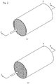
- the oxidation catalyst 4 shown in Fig. 2 is flow-through type. Any one of the flow-through type which is a through substrate having a lattice-like section as shown in Fig. 2(a) or a through substrate having a hexagonal section as shown in Fig. 2(b) may be used. A plurality of passages are configured in the through substrate. The passages may have various sectional shapes. Preferably, each of the passages of the through substrate has a hexagonal section.
- the soot filter 3 shown in Fig. 4 is partial type.
- the partial type soot filter 3 is known in the technical field (see WO 01/80978 or EP1057519 ).
- the typical partial type soot filter has a plurality of channels and a plurality of walls which are boundaries of the plurality of the channels. Each of the channels has at least one opening end, and preferably has two opening ends.
- the partial type soot filter has an element collecting particulates.
- the typical collecting element is a plurality of deviations provided in the plurality of the walls.
- Each of the walls may have any deviation or one or more deviations.
- Each of the deviations acts as an obstacle concerning particle matters in the exhaust gas flowing through the substrate.
- Each of the deviations has a flap or a wing-like shape, and the typical deviation is directed (with a certain angle) outward from a wall surface of the deviation.
- each of the deviations is connected to an opening of a wall of the carrier.
- Each opening in the wall can make the exhaust gas flow from one channel to an adjacent channel.
- a catalyst layer of the present invention is adopted to the flow-through type oxidation catalyst 4 or the partial type soot filter 3.
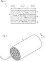
- the catalyst layer of the present invention is formed so as to be composed of an upstream-side catalyst layer 5, a downstream-side inner catalyst layer 6 and a downstream-side outer catalyst layer 7. Below, the case in which the catalyst layer of the present invention is adopted to the oxidation catalyst 4 is explained.
- the upstream-side catalyst layer 5 shown in Fig. 3 is formed at an upstream side of the exhaust gas in the substrate 8 including cordierite and the like.
- a carrier including alumina and the like is coated by the substrate 8 with a wash-coat method or the like.
- the coated upstream-side catalyst layer 5 is dried at predetermined temperature and time.
- the downstream-side inner catalyst layer 6 is formed at a downstream side of the exhaust gas in the substrate 8.
- the downstream-side outer catalyst layer 7 is formed on a surface of the downstream-side inner catalyst layer 6 (upper side of the downstream-side inner catalyst layer 6).
- the oxidation catalyst 4 in which the upstream-side catalyst layer 5, the downstream-side inner catalyst layer 6 and the downstream-side outer catalyst layer 7 are formed at the predetermined positions of the substrate 8 is baked at predetermined temperature and time.
- the oxidation catalyst 4 is configured so that lengths of the downstream-side inner catalyst layer 6 and the downstream-side outer catalyst layer 7 in the flow direction of the exhaust gas are not less than half of the whole length of the oxidation catalyst 4 in the flow direction of the exhaust gas.
- the oxidation catalyst 4 is set so that a ratio of a length of the upstream-side catalyst layer 5 and the length of the downstream-side outer catalyst layer 7 X:Y is within a range from 1:9 to 5:5.
- a carrier of the upstream-side catalyst layer 5 includes Pt and Pd as catalyst metal at a predetermined ratio (For example, a ratio of 2:1 to 4:1 and 1.8 to 2.4g/L of an amount of platinum is suitable. However, a ratio of 1:2 to 10:1 and 0.1 to 3.0g/L of the amount of platinum is permitted).
- a carrier of the downstream-side inner catalyst layer 6 includes Pt and Pd as catalyst metal at a predetermined ratio (for example, 1:1).
- a carrier of the downstream-side outer catalyst layer 7 includes only Pt as catalyst metal at an optional ratio within a predetermined range. Namely, the oxidation catalyst 4 is configured so that only the upstream-side catalyst layer 5 and the downstream-side inner catalyst layer 6 include Pd.
- An amount of Pt included in the downstream-side outer catalyst layer 7 is set optionally within the predetermined range corresponding to characteristics of the exhaust gas as mentioned above.
- amounts of Pt and Pd included in the upstream-side catalyst layer 5 and the downstream-side inner catalyst layer 6 is set predetermined amounts always regardless of the amount of Pt included in the downstream-side outer catalyst layer 7.
- the oxidation catalyst 4 is configured so that only the amount of Pt included in the downstream-side outer catalyst layer 7 is changed corresponding to the characteristics of the exhaust gas.
- the oxidation catalyst 4 configured as the above, when the exhaust gas reaches the upstream-side catalyst layer 5, CO included in the exhaust gas is oxidized to CO2 and HC is oxidized to H2O and CO2 by oxidation promotion effect of Pt and Pd included in the upstream-side catalyst layer 5. Namely, the upstream-side catalyst layer 5 removes CO and HC, which obstruct oxidation promotion effect of Pt of the downstream-side outer catalyst layer 7, from the exhaust gas. In the oxidation catalyst 4, when the exhaust gas from which CO and HC are removed reaches the downstream-side inner catalyst layer 6 and the downstream-side outer catalyst layer 7, NO included in the exhaust gas is oxidized to NO2 by oxidation promotion effect of Pt included in the downstream-side outer catalyst layer 7.
- the oxidation catalyst 4 in the oxidation catalyst 4, CO and HC are removed by the upstream-side catalyst layer 5, and Pt is contained intensively in the downstream-side outer catalyst layer 7 so as to improve conversion efficiency of NO to NO2. Accordingly, as shown in Fig. 5 , the oxidation catalyst 4 according to the present invention maintains equivalent conversion efficiency to conversion efficiency of a conventional oxidation catalyst 10 with fewer amount of Pt than that of the conventional oxidation catalyst 10.
- the upstream-side catalyst layer 5 includes Pd so as to improve ignition performance at the time of post ignition. Namely, in the oxidation catalyst 4, an inlet temperature of the oxidation catalyst 4 required for the post ignition is lowered. Accordingly, as shown in Fig. 6 , the oxidation catalyst 4 according to the present invention can perform the post ignition with lower amount of Pt than that of the conventional oxidation catalyst 10 at equivalent temperature to temperature required by the post ignition of the conventional oxidation catalyst 10.
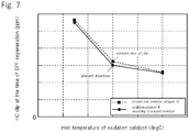
- the upstream-side catalyst layer 5 includes Pd so as to improve conversion efficiency of HC to H2O and CO2. Namely, in the oxidation catalyst 4, a slip amount of HC is lowered. Accordingly, as shown in Fig. 7 , in the oxidation catalyst 4 according to the present invention, equivalent slip amount of HC to slip amount of the conventional oxidation catalyst 10 is maintained with lower amount of Pt than that of the conventional oxidation catalyst 10.
- the oxidation catalyst 4 when the amount of Pt included in the downstream-side outer catalyst layer 7 is increased, the conversion efficiency of NO to NO2 is improved.
- the oxidation catalyst 4 when the downstream-side outer catalyst layer 7 is enlarged, the conversion efficiency of NO to NO2 is improved. Namely, in the oxidation catalyst 4, by increasing the amount of Pt included in the downstream-side outer catalyst layer 7, the oxidation catalyst 4 can be miniaturized. Accordingly, the oxidation catalyst 4 can be arranged in a smaller space.
- the substrate 8 of the oxidation catalyst 4 is shaped so as to have the hexagonal section against the flow direction of the exhaust gas, whereby the catalyst can be applied uniformly to the substrate 8 easily. Accordingly, production cost can be reduced while maintaining the performance of the oxidation catalyst 4.
- the oxidation catalyst 4 is configured so as to exhibit performance corresponding to the diesel engine by changing kind and amount of the catalyst metal included in the substrate following characteristics of the exhaust gas.
- the oxidation catalyst 10 including a surface side catalyst 11 and an inner side catalyst 12 and difference kinds of the catalyst metal are arranged in each of the catalyst, the kinds and amounts of the catalyst metal arranged in the surface side catalyst 11 and the inner side catalyst 12 are determined for the diesel engine connected thereto, and the oxidation catalyst 10 is produced through processes such as preparation, coating, drying and baking.
- the oxidation catalyst 10 when the oxidation catalyst 10 is produced for diesel engines A, B and C, it is necessary to prepare a surface side catalyst layer 11a and an inner side catalyst layer 12a as an oxidation catalyst 10A for the diesel engine A. It is necessary to prepare a surface side catalyst layer 11b and an inner side catalyst layer 12b with blending of the catalyst different from that of the catalyst layers of the oxidation catalyst 10A as an oxidation catalyst 10B for the diesel engine B. It is necessary to prepare a surface side catalyst layer 11c and an inner side catalyst layer 12c with blending of the catalyst different from that of the catalyst layers of the oxidation catalyst 10A and the oxidation catalyst 10B as an oxidation catalyst 10C for the diesel engine C. Accordingly, it is necessary to prepare total 6 catalyst layers.
- the oxidation efficiency of the oxidation catalyst 4 is not lowered without changing the kinds and amounts of the catalyst metal of the upstream-side catalyst layer 5 whose target includes oxidation of CO and HC included in the exhaust gas for each diesel engine.
- the upstream-side catalyst layer 5 is formed upstream the downstream-side inner catalyst layer 6, and the downstream-side outer catalyst layer 7 is formed in the surface of the downstream-side inner catalyst layer 6. Accordingly, in comparison with the upstream-side catalyst layer 5 and the downstream-side outer catalyst layer 7, the downstream-side inner catalyst layer 6 is hard to contact the exhaust gas and has low contribution rate to the performance of the oxidation catalyst 4. Namely, in the oxidation catalyst 4, the oxidation efficiency is not lowered without changing the kinds and amounts of the catalyst metal of the downstream-side inner catalyst layer 6 whose contribution rate to the performance is low.
- the catalyst metal included in the oxidation catalyst 4 contributes to improvement of post ignition performance.
- the contribution rate to the post ignition performance of the upstream-side catalyst layer 5 which contacts firstly HC by post injection depends strongly on the kinds and amounts of the catalyst metal included in the upstream-side catalyst layer 5.
- the downstream-side inner catalyst layer 6 and the downstream-side outer catalyst layer 7 are heated by oxidation heat of HC generated in the upstream-side catalyst layer 5 so that their oxidation speed is increased.
- the contribution rate of the downstream-side inner catalyst layer 6 and the downstream-side outer catalyst layer 7 to the post ignition performance does not depend on the kinds and amounts of the catalyst metal included in the downstream-side inner catalyst layer 6 and the downstream-side outer catalyst layer 7.
- the post injection is performed at substantially the same condition regardless of the kinds of the diesel engines A, B and C. Accordingly, in the oxidation catalyst 4, the post ignition performance is not lowered without changing the kinds and amounts of the catalyst metal of the upstream-side catalyst layer 5, the downstream-side inner catalyst layer 6 and the downstream-side outer catalyst layer 7 for the diesel engines A, B and C.
- an amount of NO included in the exhaust gas is influenced greatly by the characteristics of the diesel engine.
- the oxidation efficiency is changed by changing the amount of Pt which is the catalyst metal of the downstream-side outer catalyst layer 7 whose target is oxidation of NO included in the exhaust gas.
- the amount of Pt included in the downstream-side outer catalyst layer 7 is set optionally within a predetermined range corresponding to the characteristics of the exhaust gas. Namely, in the oxidation catalyst 4, only the amount of Pt included in the downstream-side outer catalyst layer 7 is changed corresponding to the characteristics of the diesel engine, and the upstream-side catalyst layer 5 and the downstream-side inner catalyst layer 6 are common regardless of the characteristics of the diesel engine.
- the upstream-side catalyst layer 5 ⁇ and the downstream-side inner catalyst layer 6 ⁇ with the same blending of the catalyst as the upstream-side catalyst layer 5 ⁇ and the downstream-side inner catalyst layer 6 ⁇ of the oxidation catalyst 4A (the oxidation catalyst 4B) and a downstream-side outer catalyst layer 7c with different blending of the catalyst from the downstream-side outer catalyst layer 7a of the oxidation catalyst 4A and the downstream-side outer catalyst layer 7b of the oxidation catalyst 4B as an oxidation catalyst 4C for the diesel engine C. Accordingly, it is necessary to prepare total 5 kinds of the catalyst.
- the upstream-side catalyst layer 5 ⁇ and the downstream-side inner catalyst layer 6 ⁇ are common regardless of the kinds of the diesel engines so that number of the required catalysts is reduced though number of the catalyst layers is increased from the oxidation catalyst 10.
- the oxidation catalyst for the diesel engine including the three catalyst layers having at least one of Pt and Pd is composed of the upstream-side catalyst layer 5, the downstream-side inner catalyst layer 6 and the downstream-side outer catalyst layer 7 concerning the flow direction of the exhaust gas.
- the upstream-side catalyst layer 5 and the downstream-side inner catalyst layer 6 include Pt and Pd and the downstream-side outer catalyst layer 7 includes Pt.
- the amounts of Pt and Pd included in the upstream-side catalyst layer 5 and the amounts of Pt and Pd included in the downstream-side inner catalyst layer 6 are fixed, and the amount of Pt included in the downstream-side outer catalyst layer 7 is set so as to make the oxidation efficiency not less than the predetermined value.
- HC and CO are removed by the oxidation promotion effect of Pt and Pd included in the upstream-side catalyst layer 5, whereby the oxidation promotion effect of Pt is not lowered even when the amount of Pt included in the downstream-side inner catalyst layer 6 is reduced. It is not necessary to produce the upstream-side catalyst layer 5 and the downstream-side inner catalyst layer 6 corresponding to the characteristics of the exhaust gas of the diesel engine 20. Accordingly, production cost can be reduced while maintaining the performance of the oxidation catalyst 4.
- the oxidation catalyst for the diesel engine including the three catalyst layers having at least one of Pt and Pd is composed of the upstream-side catalyst layer 5, the downstream-side inner catalyst layer 6 and the downstream-side outer catalyst layer 7 concerning the flow direction of the exhaust gas.
- the upstream-side catalyst layer 5 and the downstream-side inner catalyst layer 6 include Pt and Pd and the downstream-side outer catalyst layer 7 includes Pt.
- the amounts of Pt and Pd included in the upstream-side catalyst layer 5 and the amounts of Pt and Pd included in the downstream-side inner catalyst layer 6 are fixed, and the amount of Pt included in the downstream-side outer catalyst layer 7 is set so as to make the oxidation efficiency not less than the predetermined value.
- the length of the downstream-side outer catalyst layer 7 in the flow direction of the exhaust gas is not less than half of the whole length of the oxidation catalyst 4 in the flow direction of the exhaust gas.
- HC and CO are removed by the oxidation promotion effect of Pt and Pd included in the upstream-side catalyst layer 5, and Pt is arranged intensively in the fixed range of the downstream-side outer catalyst layer 7 so as to improve the oxidation efficiency, whereby the oxidation promotion effect of Pt is not lowered even when the amount of Pt included in the downstream-side inner catalyst layer 6 is reduced. It is not necessary to produce the upstream-side catalyst layer 5 and the downstream-side inner catalyst layer 6 corresponding to the characteristics of the exhaust gas of the diesel engine. Accordingly, production cost can be reduced while maintaining the performance of the oxidation catalyst 4.
- the present invention can be used for an art of an oxidation catalyst for a diesel engine.
Description
- The present invention relates to an oxidation catalyst for a diesel engine.
- Conventionally, as a catalyst purifying exhaust gas from a diesel engine, an oxidation catalyst oxidizing carbon monoxide (CO), hydrocarbon (HC), and nitrogen monoxide (NO) in the exhaust gas is used. The oxidation catalyst is made by applying a carrier including porous oxide such as alumina to a member of ceramic or metal so as to form a catalyst layer. The catalyst layer including precious metal such as platinum (Pt) and palladium (Pd) is known, see
JP2012217938 - In the oxidation catalyst, for exhibiting characteristics of platinum (Pt), palladium (Pd) and the like so as to improve performance of the oxidation catalyst, in consideration of temperature at each part of the catalyst and components of the exhaust gas, the oxidation catalyst in which different materials are arranged in upstream and downstream sides of a substrate is developed. For example, an art described in the
Patent Literature 1 is so. - However, in the oxidation catalyst described in the
Patent Literature 1, the carrier in which amounts of Pt and Pd are adjusted corresponding to characteristics of the exhaust gas must be applied to a predetermined position. Namely, blending of a plurality of catalysts arranged in each part of the substrate must be performed for the diesel engine connected to the oxidation catalyst, whereby it is disadvantageous because production cost is increased. - Patent Literature 1: the Japanese Patent Laid Open Gazette
2009-101252 - The present invention is provided for the above problem, and the purpose of the present invention is to provide an oxidation catalyst for a diesel engine which can reduce production cost while maintaining performance of the oxidation catalyst.
- The problems to be solved by the present invention have been described above, and subsequently, the means of solving the problems will be described below.
- According to the present invention, there is provided an apparatus according to the features of
claim 1. - According to the present invention, a plurality of passages having a hexagonal section against the flow direction of the exhaust gas are formed in the substrate.
- According to the present invention, the substrate is a partial type soot filter.
- The present invention configured as the above brings the following effects.
- According to the present invention, HC and CO are removed by oxidation promotion effect of Pt and Pd included in the upstream-side catalyst layer, whereby the oxidation promotion effect of Pt is not lowered even when the amount of Pt included in the downstream-side inner catalyst layer is reduced. It is not necessary to produce characteristics of the upstream-side catalyst layer and the downstream-side inner catalyst layer corresponding to the characteristics of the exhaust gas. Accordingly, production cost can be reduced while maintaining the performance of the oxidation catalyst.
- According to the present invention, HC and CO are removed by the oxidation promotion effect of Pt and Pd included in the upstream-side catalyst layer, and Pt is arranged intensively in the fixed range of the downstream-side outer catalyst layer so as to improve the oxidation efficiency, whereby the oxidation promotion effect of Pt is not lowered even when the amount of Pt included in the downstream-side inner catalyst layer is reduced. It is not necessary to produce the upstream-side catalyst layer and the downstream-side inner catalyst layer corresponding to the characteristics of the exhaust gas. Accordingly, production cost can be reduced while maintaining the performance of the oxidation catalyst.
- According to the present invention, the catalyst can be applied uniformly to the substrate easily. Accordingly, production cost can be reduced while maintaining the performance of the oxidation catalyst.
- According to the present invention, the catalyst layer is adopted to not only the substrate having the through hole but also the partial type soot filter. Accordingly, production cost can be reduced while maintaining the performance of the oxidation catalyst.
-
- [
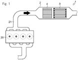
Fig. 1] Fig. 1 is a schematic drawing of an entire configuration of an exhaust purifier. - [
Fig. 2] Fig. 2(a) is a perspective view of an embodiment of an oxidation catalyst for a diesel engine according to the present invention.Fig. 2(b) is a perspective view of another embodiment of the oxidation catalyst for a diesel engine according to the present invention. - [
Fig. 3] Fig. 3 is a schematic drawing ofFig. 2(a), Fig. 2(b) andFig. 4 viewed from arrows Z. - [
Fig. 4] Fig. 4 is a perspective view of an embodiment of a partial type soot filter according to the present invention. - [
Fig. 5] Fig. 5 is a graph of conversion efficiency of a catalyst layer of the present invention and a conventional catalyst layer. - [
Fig. 6] Fig. 6 is a graph of inlet temperature required for post ignition of the catalyst layer of the present invention and the conventional catalyst layer. - [
Fig. 7] Fig. 7 is a graph of slip of HC at the time of DPF regeneration of the catalyst layer of the present invention and the conventional catalyst layer. - [
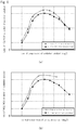
Fig. 8] Fig. 8(a) is a graph of the conversion efficiency of the catalyst layer used in the present invention corresponding to amount of catalyst metal.Fig. 8(b) is a graph of the conversion efficiency of the catalyst layer used in the present invention corresponding to size of a downstream-side outer catalyst layer. - [
Fig. 9] Fig. 9(a) is a schematic drawing of combination of catalysts of the conventional catalyst layer required for production of each diesel engine.Fig. 9(b) is a schematic drawing of combination of catalysts of the catalyst layer used in the present invention required for production of each diesel engine. - Referring to
Figs. 1 to 3 , anexhaust purifier 1 is explained. In this embodiment, an "upstream side" means an upstream side in a flow direction of fluid, and a "downstream side" means a downstream side in the flow direction of the fluid. - As shown in
Fig. 1 , theexhaust purifier 1 purifies exhaust gas discharged from adiesel engine 20. Theexhaust purifier 1 is provided in anexhaust pipe 21 connected to thediesel engine 20. Theexhaust purifier 1 has acasing 2, asoot filter 3, anoxidation catalyst 4 and the like. - The
casing 2 guides the exhaust gas to thesoot filter 3 and theoxidation catalyst 4 arranged therein. Theexhaust pipe 21 is connected to one of ends of thecasing 2, and the other end of thecasing 2 is opened to the outside via theexhaust pipe 21. Namely, thecasing 2 is provided in a middle part of theexhaust pipe 21 connected to thediesel engine 20, and is configured as an exhaust passage in which the exhaust gas from thediesel engine 20 flows from the one side (upstream side) to the other side (downstream side) (see a black arrow inFig. 1 ). - The
soot filter 3 removes particulates (soot including carbon, highly boiling hydrocarbon component (SOF) and the like) in the exhaust gas. Thesoot filter 3 is arranged inside thecasing 2. For example, thesoot filter 3 includes a porous wall such as ceramic formed lattice-like. Thesoot filter 3 is configured so as to make the exhaust gas guided by thecasing 2 pass through the porous wall. When the exhaust gas pass through the porous wall, thesoot filter 3 collects particulates in the exhaust gas. As a result, the particulates are removed from the exhaust gas. - The
oxidation catalyst 4 oxidizes carbon monoxide (hereinafter, simply referred to as "CO"), hydrocarbon (hereinafter, simply referred to as "HC"), and nitrogen monoxide (hereinafter, simply referred to as "NO") in the exhaust gas discharged from thediesel engine 20. Theoxidation catalyst 4 is arranged upstream thesoot filter 3. A predetermined range of asubstrate 8 is coated with a catalyst carrier including catalyst metal, and dried and baked at predetermined temperature and time so as to configure theoxidation catalyst 4. - The
substrate 8 of theoxidation catalyst 4 shown inFig. 3 is an optional material generally used for an exhaust gas purification catalyst, for example, a ceramic material having heat resistance such as cordierite (2MgO·2Al2O3·5SiO2), alumina, zirconia, and silicon carbide and a metal material including metal foil of stainless steel and the like, formed to be a structure having many through holes. - The carrier including catalyst metal of the
oxidation catalyst 4 is an optional metal oxide generally used as a catalyst carrier, for example, a metal oxide selected from a group including alumina (Al2O3), zirconia (ZrO2), seria (CeO2), silica (SiO2), titania (TiO2) and combination thereof. - In the
exhaust purifier 1 configured as the above, the exhaust gas from thediesel engine 20 is supplied via theexhaust pipe 21 to thecasing 2. Theexhaust purifier 1 oxidizes CO, HC and NO included in the exhaust gas by making the supplied exhaust gas pass through the oxidation catalyst 4 (see a white arrow inFig. 3 ). Furthermore, theexhaust purifier 1 collects particulates included in the supplied exhaust gas by thesoot filter 3. - Next, referring
Figs. 2 to 9 , theoxidation catalyst 4 of theexhaust purifier 1 is explained concretely. - The
oxidation catalyst 4 shown inFig. 2 is flow-through type. Any one of the flow-through type which is a through substrate having a lattice-like section as shown inFig. 2(a) or a through substrate having a hexagonal section as shown inFig. 2(b) may be used. A plurality of passages are configured in the through substrate. The passages may have various sectional shapes. Preferably, each of the passages of the through substrate has a hexagonal section. - The
soot filter 3 shown inFig. 4 is partial type. The partialtype soot filter 3 is known in the technical field (seeWO 01/80978 EP1057519 ). The typical partial type soot filter has a plurality of channels and a plurality of walls which are boundaries of the plurality of the channels. Each of the channels has at least one opening end, and preferably has two opening ends. - The partial type soot filter has an element collecting particulates. The typical collecting element is a plurality of deviations provided in the plurality of the walls. Each of the walls may have any deviation or one or more deviations. Each of the deviations acts as an obstacle concerning particle matters in the exhaust gas flowing through the substrate. Each of the deviations has a flap or a wing-like shape, and the typical deviation is directed (with a certain angle) outward from a wall surface of the deviation. Preferably, each of the deviations is connected to an opening of a wall of the carrier. Each opening in the wall can make the exhaust gas flow from one channel to an adjacent channel.
- A catalyst layer of the present invention is adopted to the flow-through
type oxidation catalyst 4 or the partialtype soot filter 3. A group including at least one of thesoot filter 3 and theoxidation catalyst 4 to which the catalyst layer of the present invention is defined as an oxidation catalyst for a diesel engine of the present invention. The catalyst layer of the present invention is formed so as to be composed of an upstream-side catalyst layer 5, a downstream-sideinner catalyst layer 6 and a downstream-sideouter catalyst layer 7. Below, the case in which the catalyst layer of the present invention is adopted to theoxidation catalyst 4 is explained. - The upstream-
side catalyst layer 5 shown inFig. 3 is formed at an upstream side of the exhaust gas in thesubstrate 8 including cordierite and the like. In the upstream-side catalyst layer 5, a carrier including alumina and the like is coated by thesubstrate 8 with a wash-coat method or the like. The coated upstream-side catalyst layer 5 is dried at predetermined temperature and time. Similarly, the downstream-sideinner catalyst layer 6 is formed at a downstream side of the exhaust gas in thesubstrate 8. Furthermore, the downstream-sideouter catalyst layer 7 is formed on a surface of the downstream-side inner catalyst layer 6 (upper side of the downstream-side inner catalyst layer 6). Theoxidation catalyst 4 in which the upstream-side catalyst layer 5, the downstream-sideinner catalyst layer 6 and the downstream-sideouter catalyst layer 7 are formed at the predetermined positions of thesubstrate 8 is baked at predetermined temperature and time. - In this case, the
oxidation catalyst 4 is configured so that lengths of the downstream-sideinner catalyst layer 6 and the downstream-sideouter catalyst layer 7 in the flow direction of the exhaust gas are not less than half of the whole length of theoxidation catalyst 4 in the flow direction of the exhaust gas. Concretely, when the upstream-side catalyst layer 5 and the downstream-sideouter catalyst layer 7 are formed so as to be adjacent to each other, theoxidation catalyst 4 is set so that a ratio of a length of the upstream-side catalyst layer 5 and the length of the downstream-side outer catalyst layer 7 X:Y is within a range from 1:9 to 5:5. By forming the downstream-sideouter catalyst layer 7 within the fixed range as the above, oxidation can be promoted efficiently. - A carrier of the upstream-
side catalyst layer 5 includes Pt and Pd as catalyst metal at a predetermined ratio (For example, a ratio of 2:1 to 4:1 and 1.8 to 2.4g/L of an amount of platinum is suitable. However, a ratio of 1:2 to 10:1 and 0.1 to 3.0g/L of the amount of platinum is permitted). A carrier of the downstream-sideinner catalyst layer 6 includes Pt and Pd as catalyst metal at a predetermined ratio (for example, 1:1). A carrier of the downstream-sideouter catalyst layer 7 includes only Pt as catalyst metal at an optional ratio within a predetermined range. Namely, theoxidation catalyst 4 is configured so that only the upstream-side catalyst layer 5 and the downstream-sideinner catalyst layer 6 include Pd. - An amount of Pt included in the downstream-side
outer catalyst layer 7 is set optionally within the predetermined range corresponding to characteristics of the exhaust gas as mentioned above. On the other hand, amounts of Pt and Pd included in the upstream-side catalyst layer 5 and the downstream-sideinner catalyst layer 6 is set predetermined amounts always regardless of the amount of Pt included in the downstream-sideouter catalyst layer 7. Namely, theoxidation catalyst 4 is configured so that only the amount of Pt included in the downstream-sideouter catalyst layer 7 is changed corresponding to the characteristics of the exhaust gas. - In the
oxidation catalyst 4 configured as the above, when the exhaust gas reaches the upstream-side catalyst layer 5, CO included in the exhaust gas is oxidized to CO2 and HC is oxidized to H2O and CO2 by oxidation promotion effect of Pt and Pd included in the upstream-side catalyst layer 5. Namely, the upstream-side catalyst layer 5 removes CO and HC, which obstruct oxidation promotion effect of Pt of the downstream-sideouter catalyst layer 7, from the exhaust gas. In theoxidation catalyst 4, when the exhaust gas from which CO and HC are removed reaches the downstream-sideinner catalyst layer 6 and the downstream-sideouter catalyst layer 7, NO included in the exhaust gas is oxidized to NO2 by oxidation promotion effect of Pt included in the downstream-sideouter catalyst layer 7. - Namely, in the
oxidation catalyst 4, CO and HC are removed by the upstream-side catalyst layer 5, and Pt is contained intensively in the downstream-sideouter catalyst layer 7 so as to improve conversion efficiency of NO to NO2. Accordingly, as shown inFig. 5 , theoxidation catalyst 4 according to the present invention maintains equivalent conversion efficiency to conversion efficiency of aconventional oxidation catalyst 10 with fewer amount of Pt than that of theconventional oxidation catalyst 10. - In the
oxidation catalyst 4, the upstream-side catalyst layer 5 includes Pd so as to improve ignition performance at the time of post ignition. Namely, in theoxidation catalyst 4, an inlet temperature of theoxidation catalyst 4 required for the post ignition is lowered. Accordingly, as shown inFig. 6 , theoxidation catalyst 4 according to the present invention can perform the post ignition with lower amount of Pt than that of theconventional oxidation catalyst 10 at equivalent temperature to temperature required by the post ignition of theconventional oxidation catalyst 10. - Furthermore, in the
oxidation catalyst 4, the upstream-side catalyst layer 5 includes Pd so as to improve conversion efficiency of HC to H2O and CO2. Namely, in theoxidation catalyst 4, a slip amount of HC is lowered. Accordingly, as shown inFig. 7 , in theoxidation catalyst 4 according to the present invention, equivalent slip amount of HC to slip amount of theconventional oxidation catalyst 10 is maintained with lower amount of Pt than that of theconventional oxidation catalyst 10. - In the
oxidation catalyst 4, as shown inFig. 8(a) , when the amount of Pt included in the downstream-sideouter catalyst layer 7 is increased, the conversion efficiency of NO to NO2 is improved. Similarly, in theoxidation catalyst 4, as shown inFig. 8(b) , when the downstream-sideouter catalyst layer 7 is enlarged, the conversion efficiency of NO to NO2 is improved. Namely, in theoxidation catalyst 4, by increasing the amount of Pt included in the downstream-sideouter catalyst layer 7, theoxidation catalyst 4 can be miniaturized. Accordingly, theoxidation catalyst 4 can be arranged in a smaller space. - The
substrate 8 of theoxidation catalyst 4 is shaped so as to have the hexagonal section against the flow direction of the exhaust gas, whereby the catalyst can be applied uniformly to thesubstrate 8 easily. Accordingly, production cost can be reduced while maintaining the performance of theoxidation catalyst 4. - Next, referring to
Fig. 9 , combination of theoxidation catalyst 4 and the diesel engine is explained. - The
oxidation catalyst 4 is configured so as to exhibit performance corresponding to the diesel engine by changing kind and amount of the catalyst metal included in the substrate following characteristics of the exhaust gas. As shown inFig. 9(a) , in the case of theoxidation catalyst 10 including asurface side catalyst 11 and aninner side catalyst 12 and difference kinds of the catalyst metal are arranged in each of the catalyst, the kinds and amounts of the catalyst metal arranged in thesurface side catalyst 11 and theinner side catalyst 12 are determined for the diesel engine connected thereto, and theoxidation catalyst 10 is produced through processes such as preparation, coating, drying and baking. - Concretely, when the
oxidation catalyst 10 is produced for diesel engines A, B and C, it is necessary to prepare a surfaceside catalyst layer 11a and an innerside catalyst layer 12a as an oxidation catalyst 10A for the diesel engine A. It is necessary to prepare a surfaceside catalyst layer 11b and an innerside catalyst layer 12b with blending of the catalyst different from that of the catalyst layers of the oxidation catalyst 10A as anoxidation catalyst 10B for the diesel engine B. It is necessary to prepare a surfaceside catalyst layer 11c and an innerside catalyst layer 12c with blending of the catalyst different from that of the catalyst layers of the oxidation catalyst 10A and theoxidation catalyst 10B as anoxidation catalyst 10C for the diesel engine C. Accordingly, it is necessary to prepare total 6 catalyst layers. - However, amounts of CO and HC included in the exhaust gas are influenced a little by the characteristics of the diesel engine. Accordingly, the oxidation efficiency of the
oxidation catalyst 4 is not lowered without changing the kinds and amounts of the catalyst metal of the upstream-side catalyst layer 5 whose target includes oxidation of CO and HC included in the exhaust gas for each diesel engine. In theoxidation catalyst 4, the upstream-side catalyst layer 5 is formed upstream the downstream-sideinner catalyst layer 6, and the downstream-sideouter catalyst layer 7 is formed in the surface of the downstream-sideinner catalyst layer 6. Accordingly, in comparison with the upstream-side catalyst layer 5 and the downstream-sideouter catalyst layer 7, the downstream-sideinner catalyst layer 6 is hard to contact the exhaust gas and has low contribution rate to the performance of theoxidation catalyst 4. Namely, in theoxidation catalyst 4, the oxidation efficiency is not lowered without changing the kinds and amounts of the catalyst metal of the downstream-sideinner catalyst layer 6 whose contribution rate to the performance is low. - Furthermore, the catalyst metal included in the
oxidation catalyst 4 contributes to improvement of post ignition performance. Namely, the contribution rate to the post ignition performance of the upstream-side catalyst layer 5 which contacts firstly HC by post injection depends strongly on the kinds and amounts of the catalyst metal included in the upstream-side catalyst layer 5. The downstream-sideinner catalyst layer 6 and the downstream-sideouter catalyst layer 7 are heated by oxidation heat of HC generated in the upstream-side catalyst layer 5 so that their oxidation speed is increased. Namely, the contribution rate of the downstream-sideinner catalyst layer 6 and the downstream-sideouter catalyst layer 7 to the post ignition performance does not depend on the kinds and amounts of the catalyst metal included in the downstream-sideinner catalyst layer 6 and the downstream-sideouter catalyst layer 7. The post injection is performed at substantially the same condition regardless of the kinds of the diesel engines A, B and C. Accordingly, in theoxidation catalyst 4, the post ignition performance is not lowered without changing the kinds and amounts of the catalyst metal of the upstream-side catalyst layer 5, the downstream-sideinner catalyst layer 6 and the downstream-sideouter catalyst layer 7 for the diesel engines A, B and C. - On the other hand, an amount of NO included in the exhaust gas is influenced greatly by the characteristics of the diesel engine. Namely, in the
oxidation catalyst 4, the oxidation efficiency is changed by changing the amount of Pt which is the catalyst metal of the downstream-sideouter catalyst layer 7 whose target is oxidation of NO included in the exhaust gas. Accordingly, in theoxidation catalyst 4, the amount of Pt included in the downstream-sideouter catalyst layer 7 is set optionally within a predetermined range corresponding to the characteristics of the exhaust gas. Namely, in theoxidation catalyst 4, only the amount of Pt included in the downstream-sideouter catalyst layer 7 is changed corresponding to the characteristics of the diesel engine, and the upstream-side catalyst layer 5 and the downstream-sideinner catalyst layer 6 are common regardless of the characteristics of the diesel engine. - Concretely, as shown in
Fig. 9(b) , when the oxidation catalyst 4 is produced for the diesel engines A, B and C, it is necessary to prepare an upstream-side catalyst layer 5α, a downstream-side inner catalyst layer 6β and a downstream-side outer catalyst layer 7a as an oxidation catalyst 4A for the diesel engine A. It is necessary to prepare the upstream-side catalyst layer 5α and the downstream-side inner catalyst layer 6β with the same blending of the catalyst as the upstream-side catalyst layer 5α and the downstream-side inner catalyst layer 6β of the oxidation catalyst 4A and a downstream-side outer catalyst layer 7b with different blending of the catalyst from the downstream-side outer catalyst layer 7a of the oxidation catalyst 4A as an oxidation catalyst 4B for the diesel engine B. It is necessary to prepare the upstream-side catalyst layer 5α and the downstream-side inner catalyst layer 6β with the same blending of the catalyst as the upstream-side catalyst layer 5α and the downstream-side inner catalyst layer 6β of the oxidation catalyst 4A (the oxidation catalyst 4B) and a downstream-side outer catalyst layer 7c with different blending of the catalyst from the downstream-side outer catalyst layer 7a of the oxidation catalyst 4A and the downstream-side outer catalyst layer 7b of the oxidation catalyst 4B as an oxidation catalyst 4C for the diesel engine C. Accordingly, it is necessary to prepare total 5 kinds of the catalyst. Accordingly, in theoxidation catalyst 4, the upstream-side catalyst layer 5α and the downstream-side inner catalyst layer 6β are common regardless of the kinds of the diesel engines so that number of the required catalysts is reduced though number of the catalyst layers is increased from theoxidation catalyst 10. - As the above, the oxidation catalyst for the diesel engine including the three catalyst layers having at least one of Pt and Pd is composed of the upstream-
side catalyst layer 5, the downstream-sideinner catalyst layer 6 and the downstream-sideouter catalyst layer 7 concerning the flow direction of the exhaust gas. The upstream-side catalyst layer 5 and the downstream-sideinner catalyst layer 6 include Pt and Pd and the downstream-sideouter catalyst layer 7 includes Pt. The amounts of Pt and Pd included in the upstream-side catalyst layer 5 and the amounts of Pt and Pd included in the downstream-sideinner catalyst layer 6 are fixed, and the amount of Pt included in the downstream-sideouter catalyst layer 7 is set so as to make the oxidation efficiency not less than the predetermined value. - According to the configuration, HC and CO are removed by the oxidation promotion effect of Pt and Pd included in the upstream-
side catalyst layer 5, whereby the oxidation promotion effect of Pt is not lowered even when the amount of Pt included in the downstream-sideinner catalyst layer 6 is reduced. It is not necessary to produce the upstream-side catalyst layer 5 and the downstream-sideinner catalyst layer 6 corresponding to the characteristics of the exhaust gas of thediesel engine 20. Accordingly, production cost can be reduced while maintaining the performance of theoxidation catalyst 4. - As the above, the oxidation catalyst for the diesel engine including the three catalyst layers having at least one of Pt and Pd is composed of the upstream-
side catalyst layer 5, the downstream-sideinner catalyst layer 6 and the downstream-sideouter catalyst layer 7 concerning the flow direction of the exhaust gas. The upstream-side catalyst layer 5 and the downstream-sideinner catalyst layer 6 include Pt and Pd and the downstream-sideouter catalyst layer 7 includes Pt. The amounts of Pt and Pd included in the upstream-side catalyst layer 5 and the amounts of Pt and Pd included in the downstream-sideinner catalyst layer 6 are fixed, and the amount of Pt included in the downstream-sideouter catalyst layer 7 is set so as to make the oxidation efficiency not less than the predetermined value. The length of the downstream-sideouter catalyst layer 7 in the flow direction of the exhaust gas is not less than half of the whole length of theoxidation catalyst 4 in the flow direction of the exhaust gas. - According to the configuration, HC and CO are removed by the oxidation promotion effect of Pt and Pd included in the upstream-
side catalyst layer 5, and Pt is arranged intensively in the fixed range of the downstream-sideouter catalyst layer 7 so as to improve the oxidation efficiency, whereby the oxidation promotion effect of Pt is not lowered even when the amount of Pt included in the downstream-sideinner catalyst layer 6 is reduced. It is not necessary to produce the upstream-side catalyst layer 5 and the downstream-sideinner catalyst layer 6 corresponding to the characteristics of the exhaust gas of the diesel engine. Accordingly, production cost can be reduced while maintaining the performance of theoxidation catalyst 4. - The present invention can be used for an art of an oxidation catalyst for a diesel engine.
-
- 3
- soot filter
- 4
- oxidation catalyst
- 5
- upstream-side catalyst layer
- 6
- downstream-side inner catalyst layer
- 7
- downstream-side outer catalyst layer
- 8
- substrate
Claims (2)
- An apparatus comprising a diesel engine and an exhaust system comprising an oxidation catalyst (4, 4a, 4B, 4C) which comprises a flow-through type substrate (8) having a plurality of passages configured therein and three catalyst layers (5, 6, 7, 5α, 6β, 7a, 7b, 7c) including at least one of Pt and Pd,
wherein the oxidation catalyst (4, 4a, 4B, 4C) is composed of an upstream-side catalyst layer (5, 5α), a downstream-side inner catalyst layer (6, 6β) and a downstream-side outer catalyst layer (7, 7a, 7b, 7c) relative to a flow direction of exhaust gas, and
the upstream-side catalyst layer (5, 5α) and the downstream-side inner catalyst layer (6, 6β) include Pt and Pd and the downstream-side outer catalyst layer (7, 7a, 7b, 7c) includes only Pt as catalyst metal, wherein a length of the downstream-side inner catalyst layer (6, 6β) and the downstream-side outer catalyst layer (7, 7a, 7b, 7c) are not less than half of the whole length of the flow-through type substrate and wherein the upstream-side catalyst layer (5, 5α) includes Pt and Pd at a ratio of 1:2 to 4:1 and 0.1 to 2.4 g/L of the amount of platinum. - The apparatus according to claim 1, wherein the plurality of passages having a hexagonal section against the flow direction of the exhaust gas are formed in the substrate (8).
Applications Claiming Priority (2)
| Application Number | Priority Date | Filing Date | Title |
|---|---|---|---|
| JP2014166914A JP6716067B2 (en) | 2014-08-19 | 2014-08-19 | Diesel oxidation catalyst |
| PCT/JP2015/072470 WO2016027698A1 (en) | 2014-08-19 | 2015-08-07 | Oxidation catalyst for diesel engines |
Publications (3)
| Publication Number | Publication Date |
|---|---|
| EP3184169A1 EP3184169A1 (en) | 2017-06-28 |
| EP3184169A4 EP3184169A4 (en) | 2018-04-11 |
| EP3184169B1 true EP3184169B1 (en) | 2020-03-25 |
Family
ID=55350644
Family Applications (1)
| Application Number | Title | Priority Date | Filing Date |
|---|---|---|---|
| EP15833235.3A Active EP3184169B1 (en) | 2014-08-19 | 2015-08-07 | Oxidation catalyst for diesel engines |
Country Status (6)
| Country | Link |
|---|---|
| US (1) | US10562013B2 (en) |
| EP (1) | EP3184169B1 (en) |
| JP (1) | JP6716067B2 (en) |
| KR (1) | KR101990711B1 (en) |
| CN (1) | CN106573229B (en) |
| WO (1) | WO2016027698A1 (en) |
Families Citing this family (4)
| Publication number | Priority date | Publication date | Assignee | Title |
|---|---|---|---|---|
| GB201315892D0 (en) | 2013-07-31 | 2013-10-23 | Johnson Matthey Plc | Zoned diesel oxidation catalyst |
| JP6753179B2 (en) * | 2016-07-08 | 2020-09-09 | いすゞ自動車株式会社 | Oxidation catalyst and exhaust gas purification system |
| JP6990606B2 (en) * | 2018-03-05 | 2022-01-12 | エヌ・イーケムキャット株式会社 | Exhaust gas treatment member |
| JP7430833B1 (en) | 2023-03-17 | 2024-02-13 | 株式会社キャタラー | Exhaust gas purification catalyst |
Family Cites Families (19)
| Publication number | Priority date | Publication date | Assignee | Title |
|---|---|---|---|---|
| DE10020170C1 (en) | 2000-04-25 | 2001-09-06 | Emitec Emissionstechnologie | Process for removing soot particles from the exhaust gas of internal combustion engine comprises feeding gas through collecting element, and holding and/or fluidizing until there is sufficient reaction with nitrogen dioxide in exhaust gas |
| US6087298A (en) * | 1996-05-14 | 2000-07-11 | Engelhard Corporation | Exhaust gas treatment system |
| FI107828B (en) | 1999-05-18 | 2001-10-15 | Kemira Metalkat Oy | Systems for cleaning exhaust gases from diesel engines and method for cleaning exhaust gases from diesel engines |
| JP4350250B2 (en) | 2000-01-27 | 2009-10-21 | 株式会社キャタラー | Exhaust gas purification catalyst |
| JP4413366B2 (en) * | 2000-03-22 | 2010-02-10 | 株式会社キャタラー | Exhaust gas purification catalyst |
| JP3855266B2 (en) * | 2001-11-01 | 2006-12-06 | 日産自動車株式会社 | Exhaust gas purification catalyst |
| US7900441B2 (en) * | 2004-02-12 | 2011-03-08 | Fleetguard, Inc. | Precat-NOx adsorber exhaust aftertreatment system for internal combustion engines |
| JP5103052B2 (en) | 2007-04-17 | 2012-12-19 | 東京濾器株式会社 | Oxidation catalyst of exhaust gas purification system for diesel engine |
| JP5328133B2 (en) | 2007-10-19 | 2013-10-30 | トヨタ自動車株式会社 | Exhaust gas purification catalyst |
| US8252258B2 (en) * | 2009-01-16 | 2012-08-28 | Basf Corporation | Diesel oxidation catalyst with layer structure for improved hydrocarbon conversion |
| JP2010179204A (en) * | 2009-02-03 | 2010-08-19 | Toyota Motor Corp | Catalyst for cleaning exhaust gas |
| US8802016B2 (en) | 2009-11-20 | 2014-08-12 | BASF Catalyst Germany GmbH | Zoned catalyzed soot filter |
| BR112013005103A2 (en) | 2010-09-02 | 2016-05-03 | Basf Se | catalyst, method for producing a catalyst, process for treating a gas stream comprising nitrogen oxide, and use of the catalyst |
| JP5287884B2 (en) * | 2011-01-27 | 2013-09-11 | トヨタ自動車株式会社 | Exhaust gas purification catalyst |
| JP2012217938A (en) * | 2011-04-08 | 2012-11-12 | Toyota Motor Corp | Exhaust gas purifying catalyst |
| US8449852B1 (en) * | 2011-12-01 | 2013-05-28 | Basf Corporation | Diesel oxidation catalysts, systems and methods of treatment |
| JP5720949B2 (en) | 2011-12-08 | 2015-05-20 | トヨタ自動車株式会社 | Exhaust gas purification catalyst |
| GB201315892D0 (en) * | 2013-07-31 | 2013-10-23 | Johnson Matthey Plc | Zoned diesel oxidation catalyst |
| WO2015087871A1 (en) | 2013-12-13 | 2015-06-18 | 株式会社キャタラー | Exhaust gas purification catalyst |
-
2014
- 2014-08-19 JP JP2014166914A patent/JP6716067B2/en active Active
-
2015
- 2015-08-07 EP EP15833235.3A patent/EP3184169B1/en active Active
- 2015-08-07 WO PCT/JP2015/072470 patent/WO2016027698A1/en active Application Filing
- 2015-08-07 US US15/505,436 patent/US10562013B2/en active Active
- 2015-08-07 KR KR1020177006146A patent/KR101990711B1/en active IP Right Grant
- 2015-08-07 CN CN201580044059.3A patent/CN106573229B/en active Active
Non-Patent Citations (1)
| Title |
|---|
| None * |
Also Published As
| Publication number | Publication date |
|---|---|
| US20170291162A1 (en) | 2017-10-12 |
| US10562013B2 (en) | 2020-02-18 |
| KR20170041810A (en) | 2017-04-17 |
| KR101990711B1 (en) | 2019-06-18 |
| JP2016043276A (en) | 2016-04-04 |
| CN106573229B (en) | 2020-05-08 |
| JP6716067B2 (en) | 2020-07-01 |
| EP3184169A4 (en) | 2018-04-11 |
| CN106573229A (en) | 2017-04-19 |
| EP3184169A1 (en) | 2017-06-28 |
| WO2016027698A1 (en) | 2016-02-25 |
Similar Documents
| Publication | Publication Date | Title |
|---|---|---|
| CN108700336B (en) | Bare heating element for heating a fluid stream | |
| EP3184169B1 (en) | Oxidation catalyst for diesel engines | |
| EP2002094B1 (en) | Low temperature diesel particulate matter reduction system | |
| EP2180936B1 (en) | Tuning particulate filter performance through selective plugging and use of multiple particulate filters to reduce emissions and improve thermal robustness | |
| RU2015124049A (en) | ZONED CATALYST ON MONOLITHIC SUBSTRATE | |
| US10107162B2 (en) | Catalyst subassembly, device comprising same for purifying exhaust gases from an internal combustion engine, modular system for the subassembly, and method for manufacturing the subassembly | |
| JP2007514104A (en) | Exhaust mechanism for lean burn internal combustion engines including particulate matter filters | |
| JP2009538727A (en) | Offline filter with improved filtration efficiency | |
| JP2015516534A (en) | Use of catalytic converter parts and catalytic converter parts of automobile exhaust gas purification equipment | |
| JP6445228B1 (en) | Exhaust gas purification catalyst | |
| JP2003184546A (en) | Method and device for catalytic conversion of gaseous pollutant in exhaust gas of combustion engine | |
| US20170122158A1 (en) | Diesel particulate filter coated with selective catalytic reduction and exhaust gas aftertreatment system including the same | |
| JP2009530521A (en) | Exhaust gas device with two exhaust gas treatment devices | |
| EP2444611A1 (en) | Exhaust purifier of internal combustion engine | |
| JP2000282852A (en) | Exhaust emission control device | |
| JP5434762B2 (en) | Exhaust gas purification filter | |
| JP2006257889A (en) | Catalytic converter | |
| CN105813715A (en) | Particulate filter designed as a wall-flow filter | |
| EP3730751B1 (en) | Structure for exhaust purification | |
| JPH1089056A (en) | Exhaust emission control catalyst for diesel engine | |
| US20200018216A1 (en) | Exhaust gas purification system | |
| CN113329806B (en) | Honeycomb body having an array of through channels with a range of hydraulic diameters | |
| JP4382574B2 (en) | Method for predicting pressure loss of honeycomb structure and method for manufacturing honeycomb structure | |
| JP6790728B2 (en) | Exhaust gas purification system for internal combustion engine | |
| JP2009233597A (en) | Catalyst for purifying exhaust gas and its manufacturing method |
Legal Events
| Date | Code | Title | Description |
|---|---|---|---|
| STAA | Information on the status of an ep patent application or granted ep patent |
Free format text: STATUS: THE INTERNATIONAL PUBLICATION HAS BEEN MADE |
|
| PUAI | Public reference made under article 153(3) epc to a published international application that has entered the european phase |
Free format text: ORIGINAL CODE: 0009012 |
|
| STAA | Information on the status of an ep patent application or granted ep patent |
Free format text: STATUS: REQUEST FOR EXAMINATION WAS MADE |
|
| 17P | Request for examination filed |
Effective date: 20170320 |
|
| AK | Designated contracting states |
Kind code of ref document: A1 Designated state(s): AL AT BE BG CH CY CZ DE DK EE ES FI FR GB GR HR HU IE IS IT LI LT LU LV MC MK MT NL NO PL PT RO RS SE SI SK SM TR |
|
| AX | Request for extension of the european patent |
Extension state: BA ME |
|
| DAV | Request for validation of the european patent (deleted) | ||
| DAX | Request for extension of the european patent (deleted) | ||
| A4 | Supplementary search report drawn up and despatched |
Effective date: 20180308 |
|
| RIC1 | Information provided on ipc code assigned before grant |
Ipc: F01N 3/10 20060101ALI20180303BHEP Ipc: F01N 3/023 20060101ALI20180303BHEP Ipc: F01N 3/28 20060101ALI20180303BHEP Ipc: B01J 35/04 20060101ALI20180303BHEP Ipc: B01J 23/44 20060101AFI20180303BHEP Ipc: F01N 3/035 20060101ALI20180303BHEP Ipc: B01D 53/94 20060101ALI20180303BHEP |
|
| STAA | Information on the status of an ep patent application or granted ep patent |
Free format text: STATUS: EXAMINATION IS IN PROGRESS |
|
| 17Q | First examination report despatched |
Effective date: 20190102 |
|
| GRAP | Despatch of communication of intention to grant a patent |
Free format text: ORIGINAL CODE: EPIDOSNIGR1 |
|
| STAA | Information on the status of an ep patent application or granted ep patent |
Free format text: STATUS: GRANT OF PATENT IS INTENDED |
|
| INTG | Intention to grant announced |
Effective date: 20191017 |
|
| GRAS | Grant fee paid |
Free format text: ORIGINAL CODE: EPIDOSNIGR3 |
|
| GRAA | (expected) grant |
Free format text: ORIGINAL CODE: 0009210 |
|
| STAA | Information on the status of an ep patent application or granted ep patent |
Free format text: STATUS: THE PATENT HAS BEEN GRANTED |
|
| AK | Designated contracting states |
Kind code of ref document: B1 Designated state(s): AL AT BE BG CH CY CZ DE DK EE ES FI FR GB GR HR HU IE IS IT LI LT LU LV MC MK MT NL NO PL PT RO RS SE SI SK SM TR |
|
| REG | Reference to a national code |
Ref country code: GB Ref legal event code: FG4D |
|
| REG | Reference to a national code |
Ref country code: AT Ref legal event code: REF Ref document number: 1247943 Country of ref document: AT Kind code of ref document: T Effective date: 20200415 Ref country code: IE Ref legal event code: FG4D |
|
| REG | Reference to a national code |
Ref country code: DE Ref legal event code: R096 Ref document number: 602015049547 Country of ref document: DE |
|
| PG25 | Lapsed in a contracting state [announced via postgrant information from national office to epo] |
Ref country code: RS Free format text: LAPSE BECAUSE OF FAILURE TO SUBMIT A TRANSLATION OF THE DESCRIPTION OR TO PAY THE FEE WITHIN THE PRESCRIBED TIME-LIMIT Effective date: 20200325 Ref country code: FI Free format text: LAPSE BECAUSE OF FAILURE TO SUBMIT A TRANSLATION OF THE DESCRIPTION OR TO PAY THE FEE WITHIN THE PRESCRIBED TIME-LIMIT Effective date: 20200325 Ref country code: NO Free format text: LAPSE BECAUSE OF FAILURE TO SUBMIT A TRANSLATION OF THE DESCRIPTION OR TO PAY THE FEE WITHIN THE PRESCRIBED TIME-LIMIT Effective date: 20200625 |
|
| PG25 | Lapsed in a contracting state [announced via postgrant information from national office to epo] |
Ref country code: BG Free format text: LAPSE BECAUSE OF FAILURE TO SUBMIT A TRANSLATION OF THE DESCRIPTION OR TO PAY THE FEE WITHIN THE PRESCRIBED TIME-LIMIT Effective date: 20200625 Ref country code: HR Free format text: LAPSE BECAUSE OF FAILURE TO SUBMIT A TRANSLATION OF THE DESCRIPTION OR TO PAY THE FEE WITHIN THE PRESCRIBED TIME-LIMIT Effective date: 20200325 Ref country code: GR Free format text: LAPSE BECAUSE OF FAILURE TO SUBMIT A TRANSLATION OF THE DESCRIPTION OR TO PAY THE FEE WITHIN THE PRESCRIBED TIME-LIMIT Effective date: 20200626 Ref country code: LV Free format text: LAPSE BECAUSE OF FAILURE TO SUBMIT A TRANSLATION OF THE DESCRIPTION OR TO PAY THE FEE WITHIN THE PRESCRIBED TIME-LIMIT Effective date: 20200325 Ref country code: SE Free format text: LAPSE BECAUSE OF FAILURE TO SUBMIT A TRANSLATION OF THE DESCRIPTION OR TO PAY THE FEE WITHIN THE PRESCRIBED TIME-LIMIT Effective date: 20200325 |
|
| REG | Reference to a national code |
Ref country code: NL Ref legal event code: MP Effective date: 20200325 |
|
| REG | Reference to a national code |
Ref country code: LT Ref legal event code: MG4D |
|
| PG25 | Lapsed in a contracting state [announced via postgrant information from national office to epo] |
Ref country code: NL Free format text: LAPSE BECAUSE OF FAILURE TO SUBMIT A TRANSLATION OF THE DESCRIPTION OR TO PAY THE FEE WITHIN THE PRESCRIBED TIME-LIMIT Effective date: 20200325 |
|
| REG | Reference to a national code |
Ref country code: DE Ref legal event code: R082 Ref document number: 602015049547 Country of ref document: DE Representative=s name: JOSTARNDT PATENTANWALTS-AG, DE Ref country code: DE Ref legal event code: R081 Ref document number: 602015049547 Country of ref document: DE Owner name: YANMAR POWER TECHNOLOGY CO., LTD., JP Free format text: FORMER OWNERS: JOHNSON MATTHEY PUBLIC LIMITED COMPANY, LONDON, GB; YANMAR CO., LTD., OSAKA, JP Ref country code: DE Ref legal event code: R081 Ref document number: 602015049547 Country of ref document: DE Owner name: JOHNSON MATTHEY PUBLIC LIMITED COMPANY, GB Free format text: FORMER OWNERS: JOHNSON MATTHEY PUBLIC LIMITED COMPANY, LONDON, GB; YANMAR CO., LTD., OSAKA, JP |
|
| PG25 | Lapsed in a contracting state [announced via postgrant information from national office to epo] |
Ref country code: SK Free format text: LAPSE BECAUSE OF FAILURE TO SUBMIT A TRANSLATION OF THE DESCRIPTION OR TO PAY THE FEE WITHIN THE PRESCRIBED TIME-LIMIT Effective date: 20200325 Ref country code: IS Free format text: LAPSE BECAUSE OF FAILURE TO SUBMIT A TRANSLATION OF THE DESCRIPTION OR TO PAY THE FEE WITHIN THE PRESCRIBED TIME-LIMIT Effective date: 20200725 Ref country code: CZ Free format text: LAPSE BECAUSE OF FAILURE TO SUBMIT A TRANSLATION OF THE DESCRIPTION OR TO PAY THE FEE WITHIN THE PRESCRIBED TIME-LIMIT Effective date: 20200325 Ref country code: RO Free format text: LAPSE BECAUSE OF FAILURE TO SUBMIT A TRANSLATION OF THE DESCRIPTION OR TO PAY THE FEE WITHIN THE PRESCRIBED TIME-LIMIT Effective date: 20200325 Ref country code: EE Free format text: LAPSE BECAUSE OF FAILURE TO SUBMIT A TRANSLATION OF THE DESCRIPTION OR TO PAY THE FEE WITHIN THE PRESCRIBED TIME-LIMIT Effective date: 20200325 Ref country code: SM Free format text: LAPSE BECAUSE OF FAILURE TO SUBMIT A TRANSLATION OF THE DESCRIPTION OR TO PAY THE FEE WITHIN THE PRESCRIBED TIME-LIMIT Effective date: 20200325 Ref country code: LT Free format text: LAPSE BECAUSE OF FAILURE TO SUBMIT A TRANSLATION OF THE DESCRIPTION OR TO PAY THE FEE WITHIN THE PRESCRIBED TIME-LIMIT Effective date: 20200325 Ref country code: PT Free format text: LAPSE BECAUSE OF FAILURE TO SUBMIT A TRANSLATION OF THE DESCRIPTION OR TO PAY THE FEE WITHIN THE PRESCRIBED TIME-LIMIT Effective date: 20200818 |
|
| REG | Reference to a national code |
Ref country code: AT Ref legal event code: MK05 Ref document number: 1247943 Country of ref document: AT Kind code of ref document: T Effective date: 20200325 |
|
| REG | Reference to a national code |
Ref country code: DE Ref legal event code: R097 Ref document number: 602015049547 Country of ref document: DE |
|
| PG25 | Lapsed in a contracting state [announced via postgrant information from national office to epo] |
Ref country code: ES Free format text: LAPSE BECAUSE OF FAILURE TO SUBMIT A TRANSLATION OF THE DESCRIPTION OR TO PAY THE FEE WITHIN THE PRESCRIBED TIME-LIMIT Effective date: 20200325 Ref country code: DK Free format text: LAPSE BECAUSE OF FAILURE TO SUBMIT A TRANSLATION OF THE DESCRIPTION OR TO PAY THE FEE WITHIN THE PRESCRIBED TIME-LIMIT Effective date: 20200325 Ref country code: IT Free format text: LAPSE BECAUSE OF FAILURE TO SUBMIT A TRANSLATION OF THE DESCRIPTION OR TO PAY THE FEE WITHIN THE PRESCRIBED TIME-LIMIT Effective date: 20200325 Ref country code: AT Free format text: LAPSE BECAUSE OF FAILURE TO SUBMIT A TRANSLATION OF THE DESCRIPTION OR TO PAY THE FEE WITHIN THE PRESCRIBED TIME-LIMIT Effective date: 20200325 |
|
| PLBE | No opposition filed within time limit |
Free format text: ORIGINAL CODE: 0009261 |
|
| STAA | Information on the status of an ep patent application or granted ep patent |
Free format text: STATUS: NO OPPOSITION FILED WITHIN TIME LIMIT |
|
| PG25 | Lapsed in a contracting state [announced via postgrant information from national office to epo] |
Ref country code: PL Free format text: LAPSE BECAUSE OF FAILURE TO SUBMIT A TRANSLATION OF THE DESCRIPTION OR TO PAY THE FEE WITHIN THE PRESCRIBED TIME-LIMIT Effective date: 20200325 |
|
| 26N | No opposition filed |
Effective date: 20210112 |
|
| PG25 | Lapsed in a contracting state [announced via postgrant information from national office to epo] |
Ref country code: MC Free format text: LAPSE BECAUSE OF FAILURE TO SUBMIT A TRANSLATION OF THE DESCRIPTION OR TO PAY THE FEE WITHIN THE PRESCRIBED TIME-LIMIT Effective date: 20200325 |
|
| REG | Reference to a national code |
Ref country code: CH Ref legal event code: PL |
|
| PG25 | Lapsed in a contracting state [announced via postgrant information from national office to epo] |
Ref country code: CH Free format text: LAPSE BECAUSE OF NON-PAYMENT OF DUE FEES Effective date: 20200831 Ref country code: LU Free format text: LAPSE BECAUSE OF NON-PAYMENT OF DUE FEES Effective date: 20200807 Ref country code: LI Free format text: LAPSE BECAUSE OF NON-PAYMENT OF DUE FEES Effective date: 20200831 |
|
| REG | Reference to a national code |
Ref country code: BE Ref legal event code: MM Effective date: 20200831 |
|
| PG25 | Lapsed in a contracting state [announced via postgrant information from national office to epo] |
Ref country code: SI Free format text: LAPSE BECAUSE OF FAILURE TO SUBMIT A TRANSLATION OF THE DESCRIPTION OR TO PAY THE FEE WITHIN THE PRESCRIBED TIME-LIMIT Effective date: 20200325 |
|
| PG25 | Lapsed in a contracting state [announced via postgrant information from national office to epo] |
Ref country code: IE Free format text: LAPSE BECAUSE OF NON-PAYMENT OF DUE FEES Effective date: 20200807 Ref country code: BE Free format text: LAPSE BECAUSE OF NON-PAYMENT OF DUE FEES Effective date: 20200831 |
|
| PG25 | Lapsed in a contracting state [announced via postgrant information from national office to epo] |
Ref country code: TR Free format text: LAPSE BECAUSE OF FAILURE TO SUBMIT A TRANSLATION OF THE DESCRIPTION OR TO PAY THE FEE WITHIN THE PRESCRIBED TIME-LIMIT Effective date: 20200325 Ref country code: MT Free format text: LAPSE BECAUSE OF FAILURE TO SUBMIT A TRANSLATION OF THE DESCRIPTION OR TO PAY THE FEE WITHIN THE PRESCRIBED TIME-LIMIT Effective date: 20200325 Ref country code: CY Free format text: LAPSE BECAUSE OF FAILURE TO SUBMIT A TRANSLATION OF THE DESCRIPTION OR TO PAY THE FEE WITHIN THE PRESCRIBED TIME-LIMIT Effective date: 20200325 |
|
| PG25 | Lapsed in a contracting state [announced via postgrant information from national office to epo] |
Ref country code: MK Free format text: LAPSE BECAUSE OF FAILURE TO SUBMIT A TRANSLATION OF THE DESCRIPTION OR TO PAY THE FEE WITHIN THE PRESCRIBED TIME-LIMIT Effective date: 20200325 Ref country code: AL Free format text: LAPSE BECAUSE OF FAILURE TO SUBMIT A TRANSLATION OF THE DESCRIPTION OR TO PAY THE FEE WITHIN THE PRESCRIBED TIME-LIMIT Effective date: 20200325 |
|
| PGFP | Annual fee paid to national office [announced via postgrant information from national office to epo] |
Ref country code: GB Payment date: 20230822 Year of fee payment: 9 |
|
| PGFP | Annual fee paid to national office [announced via postgrant information from national office to epo] |
Ref country code: FR Payment date: 20230825 Year of fee payment: 9 Ref country code: DE Payment date: 20230821 Year of fee payment: 9 |