EP3183721B1 - Method and axle-counting device for contact-free axle counting of a vehicle and axle-counting system for road traffic - Google Patents
Method and axle-counting device for contact-free axle counting of a vehicle and axle-counting system for road traffic Download PDFInfo
- Publication number
- EP3183721B1 EP3183721B1 EP15753898.4A EP15753898A EP3183721B1 EP 3183721 B1 EP3183721 B1 EP 3183721B1 EP 15753898 A EP15753898 A EP 15753898A EP 3183721 B1 EP3183721 B1 EP 3183721B1
- Authority
- EP
- European Patent Office
- Prior art keywords
- image data
- vehicle
- axles
- image
- processed
- Prior art date
- Legal status (The legal status is an assumption and is not a legal conclusion. Google has not performed a legal analysis and makes no representation as to the accuracy of the status listed.)
- Active
Links
- 238000000034 method Methods 0.000 title claims description 53
- 238000012545 processing Methods 0.000 claims description 58
- 238000005096 rolling process Methods 0.000 claims description 30
- 238000001514 detection method Methods 0.000 claims description 20
- 230000033001 locomotion Effects 0.000 claims description 20
- 238000004458 analytical method Methods 0.000 claims description 8
- 238000004590 computer program Methods 0.000 claims description 4
- 238000005286 illumination Methods 0.000 claims description 3
- 238000013459 approach Methods 0.000 description 9
- 238000011156 evaluation Methods 0.000 description 7
- 230000003287 optical effect Effects 0.000 description 7
- 238000005259 measurement Methods 0.000 description 6
- 238000012544 monitoring process Methods 0.000 description 6
- 230000005540 biological transmission Effects 0.000 description 5
- 230000002349 favourable effect Effects 0.000 description 5
- 230000006870 function Effects 0.000 description 5
- 230000004927 fusion Effects 0.000 description 5
- 238000009877 rendering Methods 0.000 description 5
- 230000003068 static effect Effects 0.000 description 5
- 238000009825 accumulation Methods 0.000 description 4
- 230000008901 benefit Effects 0.000 description 4
- 238000004364 calculation method Methods 0.000 description 3
- 238000010191 image analysis Methods 0.000 description 3
- 238000009434 installation Methods 0.000 description 3
- 238000007781 pre-processing Methods 0.000 description 3
- 238000007619 statistical method Methods 0.000 description 3
- 238000012549 training Methods 0.000 description 3
- 230000006978 adaptation Effects 0.000 description 2
- 238000005311 autocorrelation function Methods 0.000 description 2
- 238000009795 derivation Methods 0.000 description 2
- 238000010586 diagram Methods 0.000 description 2
- 238000006073 displacement reaction Methods 0.000 description 2
- 238000003384 imaging method Methods 0.000 description 2
- 238000000926 separation method Methods 0.000 description 2
- 230000003595 spectral effect Effects 0.000 description 2
- 238000003860 storage Methods 0.000 description 2
- 230000009466 transformation Effects 0.000 description 2
- 238000000844 transformation Methods 0.000 description 2
- 230000001133 acceleration Effects 0.000 description 1
- 230000002411 adverse Effects 0.000 description 1
- 238000004422 calculation algorithm Methods 0.000 description 1
- 230000007423 decrease Effects 0.000 description 1
- 230000001419 dependent effect Effects 0.000 description 1
- 238000013461 design Methods 0.000 description 1
- 230000004069 differentiation Effects 0.000 description 1
- 230000000694 effects Effects 0.000 description 1
- 238000005265 energy consumption Methods 0.000 description 1
- 238000005516 engineering process Methods 0.000 description 1
- 238000000605 extraction Methods 0.000 description 1
- 238000001914 filtration Methods 0.000 description 1
- 238000009499 grossing Methods 0.000 description 1
- 230000006872 improvement Effects 0.000 description 1
- 230000006698 induction Effects 0.000 description 1
- 238000005304 joining Methods 0.000 description 1
- 230000007246 mechanism Effects 0.000 description 1
- 238000005457 optimization Methods 0.000 description 1
- 238000003909 pattern recognition Methods 0.000 description 1
- 230000008569 process Effects 0.000 description 1
- 238000001454 recorded image Methods 0.000 description 1
- 230000009467 reduction Effects 0.000 description 1
- 239000004065 semiconductor Substances 0.000 description 1
- 239000013589 supplement Substances 0.000 description 1
- 230000002123 temporal effect Effects 0.000 description 1
- 238000012546 transfer Methods 0.000 description 1
- 238000013519 translation Methods 0.000 description 1
- 238000011144 upstream manufacturing Methods 0.000 description 1
Images


Classifications
-
- G—PHYSICS
- G06—COMPUTING; CALCULATING OR COUNTING
- G06V—IMAGE OR VIDEO RECOGNITION OR UNDERSTANDING
- G06V20/00—Scenes; Scene-specific elements
- G06V20/10—Terrestrial scenes
- G06V20/182—Network patterns, e.g. roads or rivers
-
- G—PHYSICS
- G08—SIGNALLING
- G08G—TRAFFIC CONTROL SYSTEMS
- G08G1/00—Traffic control systems for road vehicles
- G08G1/01—Detecting movement of traffic to be counted or controlled
- G08G1/015—Detecting movement of traffic to be counted or controlled with provision for distinguishing between two or more types of vehicles, e.g. between motor-cars and cycles
-
- G—PHYSICS
- G06—COMPUTING; CALCULATING OR COUNTING
- G06T—IMAGE DATA PROCESSING OR GENERATION, IN GENERAL
- G06T7/00—Image analysis
- G06T7/10—Segmentation; Edge detection
- G06T7/11—Region-based segmentation
-
- G—PHYSICS
- G06—COMPUTING; CALCULATING OR COUNTING
- G06T—IMAGE DATA PROCESSING OR GENERATION, IN GENERAL
- G06T7/00—Image analysis
- G06T7/10—Segmentation; Edge detection
- G06T7/143—Segmentation; Edge detection involving probabilistic approaches, e.g. Markov random field [MRF] modelling
-
- G—PHYSICS
- G06—COMPUTING; CALCULATING OR COUNTING
- G06T—IMAGE DATA PROCESSING OR GENERATION, IN GENERAL
- G06T7/00—Image analysis
- G06T7/10—Segmentation; Edge detection
- G06T7/194—Segmentation; Edge detection involving foreground-background segmentation
-
- G—PHYSICS
- G06—COMPUTING; CALCULATING OR COUNTING
- G06T—IMAGE DATA PROCESSING OR GENERATION, IN GENERAL
- G06T7/00—Image analysis
- G06T7/60—Analysis of geometric attributes
- G06T7/64—Analysis of geometric attributes of convexity or concavity
-
- G—PHYSICS
- G06—COMPUTING; CALCULATING OR COUNTING
- G06T—IMAGE DATA PROCESSING OR GENERATION, IN GENERAL
- G06T7/00—Image analysis
- G06T7/60—Analysis of geometric attributes
- G06T7/68—Analysis of geometric attributes of symmetry
-
- G—PHYSICS
- G06—COMPUTING; CALCULATING OR COUNTING
- G06T—IMAGE DATA PROCESSING OR GENERATION, IN GENERAL
- G06T7/00—Image analysis
- G06T7/70—Determining position or orientation of objects or cameras
- G06T7/73—Determining position or orientation of objects or cameras using feature-based methods
-
- G—PHYSICS
- G06—COMPUTING; CALCULATING OR COUNTING
- G06V—IMAGE OR VIDEO RECOGNITION OR UNDERSTANDING
- G06V20/00—Scenes; Scene-specific elements
- G06V20/50—Context or environment of the image
- G06V20/56—Context or environment of the image exterior to a vehicle by using sensors mounted on the vehicle
- G06V20/58—Recognition of moving objects or obstacles, e.g. vehicles or pedestrians; Recognition of traffic objects, e.g. traffic signs, traffic lights or roads
- G06V20/582—Recognition of moving objects or obstacles, e.g. vehicles or pedestrians; Recognition of traffic objects, e.g. traffic signs, traffic lights or roads of traffic signs
-
- G—PHYSICS
- G06—COMPUTING; CALCULATING OR COUNTING
- G06V—IMAGE OR VIDEO RECOGNITION OR UNDERSTANDING
- G06V20/00—Scenes; Scene-specific elements
- G06V20/50—Context or environment of the image
- G06V20/56—Context or environment of the image exterior to a vehicle by using sensors mounted on the vehicle
- G06V20/58—Recognition of moving objects or obstacles, e.g. vehicles or pedestrians; Recognition of traffic objects, e.g. traffic signs, traffic lights or roads
- G06V20/584—Recognition of moving objects or obstacles, e.g. vehicles or pedestrians; Recognition of traffic objects, e.g. traffic signs, traffic lights or roads of vehicle lights or traffic lights
-
- G—PHYSICS
- G06—COMPUTING; CALCULATING OR COUNTING
- G06V—IMAGE OR VIDEO RECOGNITION OR UNDERSTANDING
- G06V20/00—Scenes; Scene-specific elements
- G06V20/50—Context or environment of the image
- G06V20/56—Context or environment of the image exterior to a vehicle by using sensors mounted on the vehicle
- G06V20/588—Recognition of the road, e.g. of lane markings; Recognition of the vehicle driving pattern in relation to the road
-
- G—PHYSICS
- G08—SIGNALLING
- G08G—TRAFFIC CONTROL SYSTEMS
- G08G1/00—Traffic control systems for road vehicles
- G08G1/01—Detecting movement of traffic to be counted or controlled
- G08G1/017—Detecting movement of traffic to be counted or controlled identifying vehicles
- G08G1/0175—Detecting movement of traffic to be counted or controlled identifying vehicles by photographing vehicles, e.g. when violating traffic rules
-
- G—PHYSICS
- G08—SIGNALLING
- G08G—TRAFFIC CONTROL SYSTEMS
- G08G1/00—Traffic control systems for road vehicles
- G08G1/01—Detecting movement of traffic to be counted or controlled
- G08G1/04—Detecting movement of traffic to be counted or controlled using optical or ultrasonic detectors
-
- G—PHYSICS
- G08—SIGNALLING
- G08G—TRAFFIC CONTROL SYSTEMS
- G08G1/00—Traffic control systems for road vehicles
- G08G1/01—Detecting movement of traffic to be counted or controlled
- G08G1/056—Detecting movement of traffic to be counted or controlled with provision for distinguishing direction of travel
-
- G—PHYSICS
- G06—COMPUTING; CALCULATING OR COUNTING
- G06T—IMAGE DATA PROCESSING OR GENERATION, IN GENERAL
- G06T2207/00—Indexing scheme for image analysis or image enhancement
- G06T2207/10—Image acquisition modality
- G06T2207/10016—Video; Image sequence
- G06T2207/10021—Stereoscopic video; Stereoscopic image sequence
-
- G—PHYSICS
- G06—COMPUTING; CALCULATING OR COUNTING
- G06T—IMAGE DATA PROCESSING OR GENERATION, IN GENERAL
- G06T2207/00—Indexing scheme for image analysis or image enhancement
- G06T2207/30—Subject of image; Context of image processing
- G06T2207/30236—Traffic on road, railway or crossing
-
- G—PHYSICS
- G06—COMPUTING; CALCULATING OR COUNTING
- G06T—IMAGE DATA PROCESSING OR GENERATION, IN GENERAL
- G06T2207/00—Indexing scheme for image analysis or image enhancement
- G06T2207/30—Subject of image; Context of image processing
- G06T2207/30242—Counting objects in image
-
- G—PHYSICS
- G06—COMPUTING; CALCULATING OR COUNTING
- G06T—IMAGE DATA PROCESSING OR GENERATION, IN GENERAL
- G06T7/00—Image analysis
- G06T7/60—Analysis of geometric attributes
-
- G—PHYSICS
- G08—SIGNALLING
- G08G—TRAFFIC CONTROL SYSTEMS
- G08G1/00—Traffic control systems for road vehicles
- G08G1/01—Detecting movement of traffic to be counted or controlled
- G08G1/017—Detecting movement of traffic to be counted or controlled identifying vehicles
Definitions
- the present invention relates to a method for contactless axle counting of a vehicle on a roadway, an axle counting device for contactless axle counting of a vehicle on a roadway, a corresponding axle counting system for road traffic and a corresponding computer program product.
- Road traffic is monitored with measuring devices.
- Systems can, for example, classify vehicles or monitor speeds.
- Non-contact axle counting systems can be implemented using induction loops embedded in the roadway.
- the EP 1 361 488 B1 discloses a non-contact axle counting system for road traffic.
- the DE 10 2012 113 009 A1 discloses a method for classifying a moving vehicle by taking an image of the vehicle using a camera and determining the position and perspective orientation of the vehicle therefrom, rendered 2D views from 3D vehicle models stored in a database in positions along an expected trajectory of the vehicle are generated and compared with the recorded image of the vehicle and the vehicle is classified from the found 2D view with the greatest match by assigning the associated 3D vehicle model.
- the U.S. 2012/020526 A1 discloses a method for automatically inspecting tires of a truck with a single camera, wherein individual consecutive tire images are combined into one image.
- the present invention provides an improved method for contactless axle counting of a vehicle on a roadway according to claim 1, an axle counting device for contactless axle counting of a vehicle on a roadway according to claim 11 corresponding axle counting system for road traffic according to claim 12 and a corresponding computer program product according to claim 13 are presented.
- Advantageous configurations result from the respective dependent claims and the following description.
- a traffic monitoring system is also used to enforce rules and laws in road traffic.
- a traffic monitoring system can determine the number of axles of a passing vehicle and optionally assign them as rolling or stationary axles.
- a rolling axle can be understood to mean a loaded axle and a stationary axle to be understood to mean an unloaded axle or one that is lifted from the roadway.
- a result can be validated by a second image or an independent second method.
- Vehicles can move on a lane.
- the lane can be part of a road, so that a plurality of lanes can be arranged in parallel.
- a vehicle can be understood to mean a passenger car or a commercial vehicle such as a bus or truck.
- a vehicle can be understood to mean a trailer will.
- a vehicle can also include a trailer or semi-trailer.
- a vehicle can be understood to mean a motor vehicle or a motor vehicle with a trailer.
- the vehicles can have at least two axles.
- a motor vehicle can have at least two axles.
- a trailer may have at least one axle.
- axles of a vehicle can be assigned to a motor vehicle or to a trailer that can be assigned to the motor vehicle.
- the vehicles may have multiple axles, some of which may be unloaded.
- Unloaded axles can be spaced from the roadway and have no rotational movement.
- axles can be characterized by wheels, with the wheels of the vehicle rolling on the roadway or being able to be at a distance from the roadway when unloaded.
- idle axles can be understood to mean unloaded axles.
- An image data recording sensor can be understood to mean a stereo camera, a radar sensor or a mono camera.
- a stereo camera can be designed to create an image of the surroundings in front of the stereo camera and to make it available as image data.
- a stereo camera can be understood to mean a stereo image camera.
- a mono camera can be designed to create an image of the environment in front of the mono camera and to provide it as image data.
- the image data can also be referred to as image or image information.
- the image data can be provided as a digital signal from the stereo camera at an interface.
- a three-dimensional reconstruction of the environment in front of the stereo camera can be created from the image data of a stereo camera.
- the image data can be pre-processed in order to facilitate or enable an evaluation. In this way, different objects can be recognized or identified in the image data.
- the objects can be classified.
- a vehicle can thus be recognized and classified as an object in the image data.
- Wheels of the vehicle can thus be recognized and classified as an object or as a sub-object of an object.
- the wheels of the vehicle can be searched for and determined in a camera image or in the image data.
- An axle can be deduced from an image of a wheel.
- Information about the object can be provided as image information or object information.
- the object information can include information about a position, location, speed, direction of movement, object classification or the like.
- Object information can be assigned to an image or image data or processed image data.
- the first image data can represent first image data captured at a first point in time and the second image data can represent image data captured at a second point in time that differs from the first point in time.
- the first image data can be captured from a first viewing direction and the second image data can be from a image data captured in the second viewing direction.
- the first image data and the second image data can represent image data captured by a mono camera or a stereo camera.
- One image or pair of images can be captured and processed at a time.
- first image data can be read in at a first point in time and second image data can be read in at a second point in time that differs from the first point in time.
- the following variants can be used for the image data acquisition sensor and other sensors, including the respective data processing options.
- a mono camera is used as the image data recording sensor, a single image recording can take place. Methods that do not require 3-D information can be used, i.e. a pure 2-D single-image analysis.
- an image sequence can be read in and processed. Methods for taking a single image can be used, and it is also possible to use 3D methods that can work with unknown scaling.
- a mono camera can be combined with a radar sensor system. In this way, a single image from a mono camera can be combined with a distance measurement. In this way, a 2D image analysis can be enriched with additional information or validated.
- An evaluation of an image sequence together with a trajectory of the radar can advantageously be used. In this way, a 3D analysis with correct scaling can be carried out.
- a stereo camera is used to record the first image data and the at least second image data, a single (double) image or, alternatively, a (double) image sequence can be evaluated with functions of a 2/3-D analysis.
- a stereo camera as an image recording sensor can be combined with a radar sensor system and functions of a 2D analysis or a 3D analysis can be applied to the measurement data.
- a radar sensor system or a radar can each be replaced by a non-invasive distance-measuring sensor or a combination of non-invasive devices that perform this task.
- the method can be preceded by preparatory method steps.
- the sensor system in a preparatory step of self-calibration, can be transferred to a state of readiness for measurement.
- the sensor system can be understood to mean at least the image recording sensor.
- the sensor system can be understood to mean at least the stereo camera.
- the sensor system can be understood to mean a mono camera whose alignment with the road is determined.
- the sensor system can also be understood to mean another imaging or distance-measuring sensor system.
- the stereo camera or the sensor system for the traffic scene can optionally be set up in an initialization step. As a result of the initialization step, an alignment of the sensor system with respect to the road can be known.
- further image data can be read in at the first point in time and additionally or alternatively at the second point in time and additionally or alternatively at a third point in time that differs from the first point in time and additionally or alternatively the second point in time.
- the further image data can represent image information recorded by a stereo camera and additionally or alternatively by a mono camera and additionally or alternatively by a radar sensor system.
- a mono camera, a stereo camera and a radar sensor system can be collectively and generally referred to as a sensor system.
- a radar sensor system can be understood to mean a non-invasive distance-measuring sensor.
- the image data and the further image data can be processed in order to obtain processed image data and additionally or alternatively further processed image data.
- the number of axles of the vehicle or the assignment of the axles to stationary axles or rolling axles of the vehicle can take place using the further processed image data or the object information assigned to the further processed image data.
- the additional image data can thus advantageously lead to a more robust result.
- the additional image data can be used to validate results.
- Using a data sequence ie a plurality of image data that was captured at a plurality of points in time, can be useful in the context of self-calibration, background estimation, stitching and repetition of steps on individual images. In these cases, more than two points in time can be relevant. In this way, further image data can be recorded at least at a third point in time.
- the image data and additionally or alternatively image data derived therefrom can be homographically rectified using the object information and provided as processed image data, so that a side view of the vehicle is homographically rectified in the processed image data.
- a three-dimensional reconstruction of the object ie the vehicle, can be used to provide a view or image data by calculating homography, as would be provided as image data with an orthogonal view of a vehicle side or image of the vehicle.
- wheels of the axles can be shown as circular and rolling axles at the same height as the homographically prepared ones Image data are played back. Stationary axes can have a different height.
- the processing step includes a stitching step.
- an image of a vehicle can extend over a plurality of images. Overlapping image areas can be identified and superimposed. Similar functions can be known from panoramic photography.
- the distance between the detection device, such as a stereo camera, and the imaged vehicle is smaller and in the case of longer vehicles, an image can be created on which the vehicle is imaged in its entirety.
- a distance between the roadway and the stereo camera can be smaller than without the use of stitching or wide-angle lenses that distort an image.
- An overall view of the vehicle can advantageously be generated from the combined image data, which offers a constantly high local pixel resolution of image details compared to an individual view.
- the processing step can include a step of fitting primitives in the first image data and additionally or alternatively in the second image data and additionally or alternatively first image data derived therefrom and additionally or alternatively second image data derived therefrom in order to produce a result of the fitted and additionally or alternatively provide fitted primitives as object information.
- Primitives can be understood to mean, in particular, circles, ellipses or segments of circles or ellipses.
- a quality measure for an adaptation of a primitive to a wheel contour can be determined as object information.
- a circle fitting in a transformed side view, ie prepared image data, for example by a step of homographic rectification, can be secured by an ellipse fitting in the original image, ie the image data, at the corresponding point.
- An accumulation of center estimates of the primitives can indicate an increased probability of a wheel center and thus an axle.
- the processing step includes a step of detecting radial symmetries in the first image data and additionally or alternatively in the second Image data and additionally or alternatively first image data derived therefrom and additionally or alternatively second image data derived therefrom in order to provide a result of the detected radial symmetries as object information.
- the step of recognizing radial symmetries can include pattern recognition using accumulation methods. For example, transformations into polar coordinates can be carried out for candidates for centers of symmetry, with translation symmetries being able to result in the polar representation. Translational symmetries can be recognized by means of displacement detection. Scored candidates for centers of radial symmetry indicative of axes can be provided as object information.
- the step of processing can include a step of classifying a plurality of image areas using at least one classifier in the first image data and additionally or alternatively in the second image data and additionally or alternatively first image data derived therefrom and additionally or alternatively second image data derived therefrom, to provide a result of the classified image areas as object information.
- a classifier can be trained in advance. The parameters of the classifier can be determined with reference data sets.
- a probability value which represents a probability for a wheel or an axle, can be assigned to an image area or a region in the image data using the classifier.
- a background estimate can be made using statistical methods.
- a static background in the image data can be recognized using statistical methods, and a probability of a static image background can be determined.
- Image areas adjacent to a vehicle can be associated with a road surface or lane.
- Information about the static image background can also be transformed into another view, for example a side view.
- the processing step can include a step of determining contact points on the roadway using the first image data and additionally or alternatively the second image data and additionally or alternatively first image data derived therefrom and additionally or alternatively second image data derived therefrom in order to determine contact points of the vehicle on the Provide roadway as object information. If a contact point is assigned to an axle, it can be a rolling axle. Thereby can a 3D reconstruction of the vehicle from the image data of the stereo camera can be used. Positions at which a vehicle or an object touches the roadway in the three-dimensional model or is within a predetermined tolerance range have a high probability of an axle, in particular a rolling axle.
- the processing step can include a step of model-based recognition of wheels and/or axles using the first image data and additionally or alternatively the second image data and additionally or alternatively first image data derived therefrom and additionally or alternatively second image data derived therefrom in order to identify wheel contours and / or provide axles of the vehicle as object information.
- a three-dimensional model of a vehicle can be generated from the image data of the stereo camera. From the three-dimensional model of the vehicle no wheel contours and thus axles are determined. The number of vehicles can be determined from a 3D reconstruction.
- the processing step comprises a step of projecting an image of a side view of the vehicle from the image data of the stereo camera.
- certain object information from a three-dimensional model can be used in a transformed side view to identify axes.
- the three-dimensional model can be subjected to a homographic rectification step.
- the step of processing can include a step of determining self-similarities using the first image data and additionally or alternatively the second image data and additionally or alternatively first image data derived therefrom and additionally or alternatively second image data derived therefrom and additionally or alternatively the object information in order to Provide self-similarities certain wheel positions of the vehicle as object information.
- An image of an axle or a wheel of a vehicle in a side view may be similar to an image of another axle of the vehicle in the side view.
- Self-similarities can be determined using an autocorrelation. Peaks in a result of the autocorrelation function can show similarities in image content in the image data. A number and spacing of the peaks can provide an indication of axis positions.
- the processing step includes a step of analyzing motion blurring using the first image data and additionally or alternatively the second image data and additionally or alternatively first image data derived therefrom and additionally or alternatively second image data derived therefrom and additionally or alternatively the object information to represented axes assigned to stationary axles of the vehicle and additionally or alternatively to rolling axles of the vehicle and provide as object information.
- Rolling or live axles may exhibit some motion blur due to wheel rotation.
- Information about a rolling axis can be obtained from a specific motion blur.
- Stationary axles can be raised on the vehicle so that the associated wheels are not used. In-use or rolling axis candidates may exhibit motion blur due to wheel rotation.
- the different motion blurs can mark features for recognizing stationary and moving axles.
- the image sharpness can be estimated by summing the magnitudes of the second derivatives in the image. Due to the rotational movement, wheels on moving axles can provide a less sharp image than wheels on stationary axles.
- the motion blur can be actively controlled and measured. Correspondingly high exposure times can be used for this purpose.
- the resulting images can show straight-line movements along the direction of travel with stationary axles and radial courses with moving axles.
- first and second image data are read which represent image data recorded by an image data recording sensor arranged to the side of the roadway.
- Such an embodiment of the approach presented here offers the advantage of being able to carry out a very precise, non-contact axle count of the vehicle, since the defined viewing direction from the side of the road to a vehicle passing an axle counting unit means that objects in the edge area of the vehicle from the Image data recording sensor monitored area can be largely minimized, avoided or suppressed entirely.
- first and second image data can be read in using a Flash unit to improve the illumination of a detection area of the Image data recording sensor were recorded.
- a flash unit can be an optical unit designed to emit light, for example in the visible or infrared spectral range, into an area monitored by an image data acquisition sensor in order to obtain a sharper or brighter image of the vehicle passing this area.
- vehicle data of the vehicle passing the image data acquisition sensor are also read in in the reading step, with the number of axles being determined using the read-in vehicle data in the determining step.
- vehicle data can be understood, for example, as one or more of the following parameters: speed of the vehicle relative to the image data recording sensor, distance/position of the vehicle to the image data recording sensor, size/length of the vehicle, or the like.
- the axle counting device is designed to carry out or implement the steps of a variant of a method presented here in corresponding devices.
- the object on which the invention is based can also be achieved quickly and efficiently by this embodiment variant of the invention in the form of a device.
- the device for detecting, the device for tracking and the device for classifying can be partial devices of the device for processing.
- an axle counting device can be understood to mean an electrical device that processes sensor signals and outputs control and/or data signals as a function thereof.
- the axle counting device also simply referred to as a device, can have an interface that can be configured as hardware and/or software.
- the interfaces can be part of a so-called system ASIC, for example, which contains a wide variety of functions of the device.
- the interfaces can be separate integrated circuits or to consist at least partially of discrete components.
- the interfaces can be software modules which are present, for example, on a microcontroller alongside other software modules.
- Axle counting system for road traffic which comprises at least one stereo camera and a variant of an axle counting device described here, in order to contactlessly count axles of a vehicle on a roadway.
- the sensors of the axle counting system can be arranged or mounted on a mast or in a tower next to the roadway.
- a computer program product with a program code that can be stored on a machine-readable medium such as a semiconductor memory, a hard disk memory or an optical memory and is used to carry out the method according to one of the embodiments described above is also advantageous if the program product is used on a computer or a device is performed.
- FIG. 12 is an illustration of an axle counting system 100 according to an embodiment of the present invention.
- the axle counting system 100 is arranged next to a roadway 102 .
- Two vehicles 104 , 106 are shown on roadway 102 . In the exemplary embodiment shown, these are commercial vehicles 104, 106 or trucks 104, 106. A direction of travel of the two vehicles 104, 106 is shown in FIG 1 left to right.
- the vehicle 104 in front is a truck 104 with a box body.
- the rear vehicle 106 is an articulated lorry with a trailer.
- the vehicle 104 ie the truck with a box body, has three axles 108.
- the three axles 108 are rolling or loaded axles 108.
- the vehicle 106 ie the articulated lorry with trailer, has a total of six axles 108, 110.
- the articulated lorry has three axles 108, 110 and the trailer has three axles 108, 110.
- two axles 108 are in contact with the roadway and one axle 110 is arranged above the roadway.
- Axles 108 are rolling or loaded axles 108 and axles 110 are stationary or unloaded axles 110.
- the axle counting system 100 includes at least one image data acquisition sensor and an axle counting device 114 for contactless axle counting of a vehicle 104, 106 on the roadway 102.
- the image data acquisition sensor is designed as a stereo camera 112 .
- the stereo camera 112 is designed to capture an image in the viewing direction in front of the stereo camera 112 and to provide it as image data 116 at an interface.
- the axle counting device 114 is designed to receive and evaluate the image data 116 provided by the stereo camera 112 in order to determine a number of the axles 108, 110 of the vehicles 104, 106.
- the axle counting device 114 is designed to distinguish between the axles 108, 110 of a vehicle 104, 106 as rolling axles 108 and stationary axles 110.
- the number of axles 108, 110 is determined based on the number of wheels observed.
- the axle counting system 100 includes as in 1 At least one additional sensor system 118 is shown.
- the additional sensor system 118 is an additional stereo camera 118, a mono camera 118 or a radar sensor system 118.
- the axle counting system 100 can have a plurality of the same or different ones various sensors 118 include.
- the image data recording sensor is a mono camera, such as is shown here as additional sensor system 118 in 1 is shown.
- the image data recording sensor can be designed as a stereo camera 112 or as a mono camera 118 in variants of the exemplary embodiment shown.
- the axle counting system 100 also includes a device 120 for the temporary storage of data and a device 122 for the remote transmission of data.
- the system 100 further includes an uninterruptible power supply 124.
- the axle counting system 100 is mounted in a column or on a mast on a traffic control bridge or gantry sign above the roadway 102 or laterally above the roadway 102, in contrast to the exemplary embodiment shown here.
- An exemplary embodiment of one described here can be used in connection with a system for detecting a toll obligation for the use of traffic routes.
- a vehicle 104 , 106 can advantageously be determined with a low latency while the vehicle 104 , 106 is driving past an installation location for the axle counting system 100 .
- a mast installation of the axle counting system 100 includes in one embodiment as in 1 shown components for data acquisition and data processing, for at least temporary storage and long-distance transmission of data and for uninterruptible power supply.
- a calibrated or self-calibrating stereo camera 112 can be used as the sensor system.
- a radar sensor 118 is optionally used. Furthermore, the use of a mono camera with an additional depth-measuring sensor is possible.
- the axle counting device 114 can be the in 1 act axle counting device 114 shown.
- the vehicle can also be an exemplary embodiment of an in 1 shown vehicle 104, 106 act.
- the axle counting device 114 has at least one interface 230 for reading in, a device 232 for processing and a device 234 for determining.
- the interface 230 for reading in is designed to read in at least first image data 116 at a first point in time t1 and second image data 216 at a second point in time t2.
- the first time t1 and the second time t2 are two different times t1, t2.
- the image data 116, 216 represent at a Interface of a stereo camera 112 provided image data comprising an image of a vehicle on a roadway. At least one image of a partial area of the vehicle is shown or represented in the image data. As described below, at least two images or image data 116, each of which depicts a partial area of the vehicle, can be combined to form further image data 116 in order to obtain a complete image from a viewing direction of the vehicle.
- the device 232 for processing is designed to provide processed first image data 236 and processed second image data 238 using the first image data 116 and the second image data 216 .
- the device 232 for processing comprises at least one device for detection, one device for tracking and one device for classification.
- the detection device at least one object is detected in the first image data 116 and the second image data 216 and provided as object information 240 associated with the respective image data and representing the object.
- the object information 240 includes, for example, a size, a location or a position of the detected object.
- the device for tracking is designed to track the at least one object using the object information 240 in the image data 116, 216 over time.
- the device for tracking is thus also designed to predict a position or location of the object at a future time.
- the device for classifying is designed to identify the at least one object using object information 240, that is to say, for example, to differentiate between vehicles with a box body and articulated lorries with a trailer.
- object information 240 that is to say, for example, to differentiate between vehicles with a box body and articulated lorries with a trailer.
- the number of possible vehicle classes can be chosen almost arbitrarily.
- Device 234 for determining is designed to assign a number of axles of the vehicle depicted or an assignment of the axles to stationary axles and rolling axles using processed first image data 236, processed second image data 238 and object information 240 assigned to image data 236, 238 determine. Furthermore, the device 234 for determining is designed to provide a result 242 at an interface.
- device 114 is designed to create a three-dimensional reconstruction of the vehicle and to provide it for further processing.
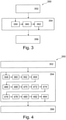
- FIG. 3 shows a flowchart of a method 350 according to an embodiment of the present invention.
- Method 350 for contactless axle counting of a vehicle on a roadway comprises at least three steps, a step 352 of reading in, a step 354 of processing and a step 356 of determining.
- step 352 of reading in first image data are read in at a first point in time and second image data are read in at a second point in time.
- the first image data and the second image data are read in in parallel.
- the first image data represent image data captured by a stereo camera at a first point in time and the second image data represent image data captured at a second point in time that differs from the first point in time.
- the image data include at least information about an image of a vehicle on a roadway. In one embodiment, at least a portion of the vehicle is depicted.
- processed first image data, processed second image data and object information associated with the image data are processed using the first image data and the second image data.
- a number of axles of the vehicle is determined using the processed first image data, the processed second image data and the object information associated with the processed image data. In a favorable exemplary embodiment, in addition to the total number of axles of the vehicle in step 356 of determination, these are also differentiated according to stationary axles and rolling axles, or the total number is assigned to these.
- Step 354 of processing comprises at least three sub-steps 358, 360, 362.
- sub-step 358 of detecting at least one object is detected in the first image data and the second image data and object information that is assigned to the first image data and the second image data and represents the object is provided .
- sub-step 360 of tracking the at least one object detected in sub-step 358 is tracked over time using the object information in the image data.
- the sub-step 362 of classifying that follows the sub-step 360 of tracking the at least one object is classified using the object information.
- FIG. 3 shows a flowchart of a method 350 according to an embodiment of the present invention.
- the method 350 for contactless axle counting of a vehicle on a roadway can be an exemplary embodiment of the 3 shown method 350 act for contactless axle counting of a vehicle on a roadway.
- the method comprises at least a step 352 of reading in, a step 354 of processing and a step 356 of determining.
- the step 354 of processing includes at least the in 3 described partial steps 358 of detecting, 360 of tracking and 362 of classifying.
- Method 350 in step 354 of processing further sub-steps.
- the order of the optional sub-steps of step 354 of processing described below can be changed, and in exemplary embodiments that are not shown, only some of the optional steps can be carried out.
- the axles are counted and differentiated according to stationary and rolling axles, advantageously by a selection and combination of the following steps.
- the optional sub-steps provide a result as a supplement to the object information and additionally or alternatively as processed image data.
- the object information can thus be expanded by each partial step.
- the object information includes information about the vehicle with the number of axles and an assignment to stationary axles and rolling axles.
- step 356 of determining a number of axes and, optionally, an assignment of the axes to rolling axes and stationary axes can be determined using the object information.
- a homographic rectification of the side view of a vehicle takes place.
- the trajectory of the cuboid circumscribing the vehicle or of the cuboid circumscribing the object detected as a vehicle is determined from the 3D reconstruction over the course of the vehicle movement over time. This means that the rotational position of the vehicle in relation to the measuring device and the direction of travel are known at all times after initialization. With a known rotational position, a homograph calculation can be used to generate a view as would be produced with an orthogonal view of the side of the vehicle, with this statement being restricted to a planar area. As a result, tire contours are displayed as approximately circular and the wheels used are at the same height in the transformed image. In this case, a transformed image can be understood to mean processed image data.
- the step 354 of processing optionally includes an optional sub-step 466 of stitching of image recordings in the close-up range.
- the local image resolution decreases with increasing distance from the measuring system and thus from the cameras such as the stereo camera.
- For an approximately constant resolution of a vehicle such as a long tractor unit multiple images are combined in which different sections of a long vehicle are each close to the camera.
- the combination of the overlapping partial images can be well initialized by the known speed of the vehicle.
- the result of the joining is optimized with local image comparisons in the overlapping area.
- the end result is processed image data or an image of a side view of the vehicle with an approximately constant and high image resolution.
- the step 354 of rendering includes a step 468 of fitting primitives in the original image and in the rectified image.
- the original image can be understood to mean the image data and the corrected image can be understood to mean the processed image data.
- the fitting of geometric primitives is used as a possibility for identifying wheels in the image or the image data.
- circles and ellipses and segments of circles or ellipses are to be understood as primitives in this exemplary embodiment.
- Classic estimation methods provide quality measures for an adaptation of a primitive to a wheel contour.
- the circle fitting in the transformed side view can be secured by an ellipse fitting in the original image at the corresponding point. Fitting segments results in candidates for the respective associated midpoints. An accumulation of such center point estimates indicates an increased probability of a wheel center point and thus an axle.
- the step 354 of processing includes an optional sub-step 470 of detecting radial symmetries.
- Wheels are characterized by radially symmetrical patterns in the image, i.e. the image data. These patterns can be recognized using accumulation methods. For this purpose, transformations in polar coordinates are carried out for candidates of centers of symmetry. Translational symmetries arise in the polar representation, which are recognized by means of displacement detection. The result is evaluated candidates for centers of radial symmetry, which in turn indicate wheels.
- the step 354 of rendering includes a step 472 of classifying image regions.
- classification methods are used to identify wheel areas in the image.
- a classifier is trained in advance, i.e. the parameters of the classifier are calculated with annotated reference data sets.
- an image area ie a sub-area of the image data, is given a value by the classifier, which describes the probability that it is a wheel area.
- Such an image area can be pre-selected using the other methods presented here.
- the step 354 of rendering includes an optional sub-step 474 of background estimation with a camera.
- This uses the fact that static background in the image can be recognized using statistical methods. By accumulating processed, local gray values, a scatter can be determined that correlates with the probability of a static image background.
- image areas that border on the vehicle can be assigned to the road surface.
- These background points can also be transformed into another view, for example the side view. This offers the possibility of delimiting the contours of the wheels against the background.
- the round edges are a characteristic identifying feature.
- the step 354 of processing includes an optional step 476 for determining contact points on the road surface in the image data of the stereo camera or a 3D reconstruction using the image data.
- the 3D reconstruction of the stereo system can be used to identify candidate wheel positions.
- the 3D estimation of the road surface in combination with the 3D object model can be used to determine positions in 3D space that are very close to or touch the road surface. At these points the presence of a wheel is likely, and there are candidates for further evaluation.
- the step 354 of processing optionally includes a sub-step 478 of model-based recognition of the wheels from the 3D object data of a vehicle.
- the 3D object data can be understood as the object information.
- a high-quality 3D model of a vehicle can be generated by bundle block adjustment or other methods of 3D optimization. This enables model-based 3D recognition of the wheel contours.
- the step 354 of rendering includes a step 480 of projection from the 3D measurement into the image of the side view.
- Information determined from the 3D model is used in the transformed side view, for example to identify stationary axes.
- 3D information is subjected to the same homography of the side view.
- the 3D object is projected into the plane of the vehicle side. The distance of the 3D object from the side plane is known. The projection of the 3D object in the view of the vehicle side can then be seen in the transformed view.
- the step 354 of processing includes an optional sub-step 482 of checking for self-similarities.
- Wheel areas of a vehicle usually look very similar when viewed from the side. This circumstance can be used by checking self-similarities of a specific image region of the side view using autocorrelation.
- a peak (peaks) or a plurality of peaks in the result of the autocorrelation function indicates shifts in the image that lead to the greatest possible similarity of the image content.
- Conclusions about possible wheel positions can be drawn from the number and spacing of the peaks.
- the step 354 of processing includes an optional step 484 of analyzing motion blur to detect moving and still axes.
- Stationary axles are raised on the vehicle so that the associated wheels are not used.
- Candidates for used axes are characterized by motion blur due to wheel rotation.
- the different motion blurs mark features for recognizing stationary and moving or rolling or loaded axles.
- the image sharpness is estimated by summing the magnitudes of the second derivatives in the image. Due to the rotational movement, wheels on moving axles offer a less sharp image than wheels on stationary axles. The result is an initial estimate of which axes are stationary or moving. Further information for the differentiation can be drawn from the 3D model.
- the motion blur is optionally actively controlled and measured. Correspondingly long exposure times are used for this purpose.
- the resulting images show straight-line movements along the direction of travel with stationary axles and radial movements with moving axles.
- step 354 of processing comprises at least three partial steps 358, 360, 362.
- step 358 of detection objects are detected, ie objects on the road in the monitoring area are detected.
- Data fusion with radar is advantageous here.
- step 360 of tracking objects are tracked, ie moving objects are tracked over time.
- An extension or combination with an optional step of fusing for data fusion with radar is advantageous in step 360 of tracking.
- sub-step 362 of classification objects are classified or candidates for trucks are identified.
- data fusion with radar is advantageous.
- the method has a calibration step (not shown) and a traffic scene setup step (not shown).
- a self-calibration or a transfer of the sensors to a state of readiness for measurement optionally takes place.
- an alignment of the sensor system with the road is known.
- the described method 350 advantageously uses 3D information and image information, with a corresponding device, such as in 1 shown is installable on a single pole.
- a stereo camera and, optionally, a radar sensor system creates a robust system with robust, inexpensive sensors and without moving parts.
- the method 350 advantageously has a robust detection performance, with a corresponding device, as in Fig. 1 or Fig. 2 shown has a system capability for self-calibration and self-setup.
- FIG. 12 shows a schematic representation of an axle counting system 100 according to an exemplary embodiment of the present invention.
- the axle counting system 100 is installed in a column.
- the axle counting system 100 can be an embodiment of an in 1 axle counting system 100 shown act.
- the axle counting system 100 includes in the in figure 5 shown embodiment two cameras 112, 118, an axle counting device 114 and a device 122 for remote transmission of data.
- the two cameras 112, 118 and the axle counting device 114 are also shown separately next to the axle counting system 100.
- the cameras 112, 118, the axle counting device 114 and the device 122 for the long-distance transmission of data are coupled to one another via a bus system.
- the named devices of the axle counting system 100 are coupled to one another via an Ethernet bus.
- Both the stereo camera 112 and the other Sensor system 118 which is representative of a stereo camera 118 as well as a mono camera 118 or a radar sensor system 118, are in figure 5 illustrated embodiment shown as a sensor 112, 118 with remote sensor head or camera head.
- the circuit board assigned to the sensor head or camera head includes devices for pre-processing the recorded sensor data and for providing the image data.
- the sensor head and the associated circuit board are coupled via the already mentioned Ethernet bus and in another embodiment, which is not shown, via a proprietary sensor bus such as Camera Link, Firewire IEEE-1394 or GigE (Gigabit Ethernet) with power -over Ethernet (PoE).
- the circuit board assigned to the sensor head, the device 122 for remote transmission of data and the axle counting device 114 are coupled to one another via a standardized bus such as PCI or PCIe.
- a standardized bus such as PCI or PCIe.
- the axle counting system 100 has more than two sensors 112, 118.
- the use of two independent stereo cameras 112 and a radar sensor system 118 is conceivable.
- FIG. 6 12 shows a conceptual representation of a classification according to an embodiment of the present invention.
- a classification can, for example, in one embodiment in 4 described step 472 of classification can be used as a sub-step of step 354 of processing the method 350 .
- a HOG-based detector is used.
- the abbreviation HOG stands for "Histograms of Oriented Gradients" and describes a method for obtaining features in image processing.
- the classification creates an independent learning of the object properties (template) based on provided training data, in this case sets are essentially learned from object edges in different positions, lengths and orientations. In one embodiment, object properties are trained over a number of days.
- the classification shown here creates real-time processing through a cascade approach and pixel-precise query mechanism, for example query generation through stereo pre-processing.
- the step 472 of classification described in detail has a first partial step 686 of generating a training data set.
- the training data set is generated using a few 1000 images.
- the HOG features are calculated from gradients and statistics.
- the object properties are learned and a universal textual representation is learned.
- Figures 7 to 9 show a photographic side view 792, 894, 996 and representation of detected axes 793 according to an embodiment of the present invention.
- the detected axles 793 can be rolling axles 108 as well as stationary axles 110 of an in 1 Act embodiment shown.
- the axes can be recognized with the in 1 and 2 Axle counting system 100 shown.
- a vehicle 104, 106 is shown in each of the photographic side views 792, 894, 996.
- a tow truck 104 with another vehicle on the bed is shown in a side view 792 according to an embodiment of the present invention. If the axle counting system is used to record and calculate a fee for using traffic routes, then only the rolling or stationary axles of the tow truck 104 are relevant. in the in 7 In the photographic side view 792 shown, in addition to two (rolling) axles 108, 793 of the tow truck 104, at least one axle 793 of the vehicle located on the loading area of the vehicle 104 is recognized and marked accordingly for an observer of the photographic side view 792.
- Vehicle 106 in a side view 894 according to an exemplary embodiment of the present invention.
- Vehicle 106 is shown as an articulated lorry with a trailer similar to that in FIG 1 shown embodiment.
- the tractor or semitrailer has two axles, the trailer has three axles.
- a total of five axes 793 are recognized and marked in the side view 894 .
- the two axles of the articulated lorry and the first two axles of the semi-trailer following the articulated lorry are rolling axles 108, and the third axle of the semi-trailer is a stationary axle 110.
- FIG. 9 shows a vehicle 106 in a side view 996 according to an exemplary embodiment of the present invention.
- the vehicle 106 is similar to that shown in FIG 8 a semi-trailer truck with a trailer. This in 9
- the vehicle 106 shown has a total of four axles 108, which are marked as recognized axles 793 in the illustration.
- the four axles 108 are rolling axles 108.
- 10 12 is a conceptual representation of a fitting from Primitiva according to an embodiment of the present invention.
- a fitting of primitives can, for example, in one embodiment in 4 described step 468 of fitting primitives may be used as a sub-step of step 354 of rendering method 350 .
- the inside 4 described step 468 of the fitting of primitives comprises in an in 10 illustrated embodiment three sub-steps, wherein in a first sub-step an extraction of relevant contours 1097, 1098 takes place by means of a bandpass filter and edge detector, in a second sub-step a pre-filtering of contours 1097, 1098 is performed and in a third sub-step a fitting of ellipses 1099 or circles 1099 filtered contours 1097, 1098.
- a fitting can be understood to mean fitting in or adapting.
- a primitive 1099 can be understood as a geometric (base) shape. So will in the in 10 In the exemplary embodiment shown, a primitive 1099 is understood to be a circle 1099; in an alternative exemplary embodiment, which is not shown, a primitive 1099 is understood to be an ellipse 1099.
- a planar geometric object can be understood by a primitive. Objects can advantageously be compared with primitives stored in a database. In this way, the database with the primitives can be created in a sub-step of learning.
- a first closed contour 1097 is shown, into which a circle 1099 is fitted as a primitive 1099.
- a contour of a circle segment 1098 is shown underneath, which follows a partial area of the primitive 1099 in the form of a circle 1099 .
- a corresponding segment 1098 is recognized and recognized as part of a wheel or axle by fitting into the primitive.
- 11 12 shows a conceptual representation of detecting radial symmetries according to an embodiment of the present invention.
- a detection of radial symmetries can, for example, in one embodiment in 4 described step 470 of detecting radial symmetries can be used as a sub-step of step 354 of preparing the method 350 .
- the wheels and thus the axles of a vehicle appear as radially symmetrical patterns in the image data.
- 11 shows four figures 1102, 1104, 1106, 1108.
- a first figure 1102, in 11 located at the top right, shows a section of an image or image data with a wheel depicted in it. Such a section is also referred to as a "region of interest", ROI or "area of interest”.
- the area selected in the image 1102 represents a greatly enlarged area or section of image data or processed image data.
- the displays 1102, 1104, 1106, 1108 or images 1102, 1104, 1106, 1108 are arranged counterclockwise.
- the image area selected in the first figure is shown transformed in polar coordinates at the top left.
- the third figure 1106 in 11 bottom left shows a histogram of the polar plot 1104 after applying a Sobel operator. In this case, a first derivation of the pixel brightness values is determined, with smoothing being carried out at the same time orthogonally to the derivation direction.
- a frequency analysis is shown below right.
- the four images 1102, 1104, 1106, 1108 show four partial steps or aspects that are carried out one after the other to detect radial symmetries: a local environment in image 1102, a polar image in image 1104, a histogram in image 1106 and finally a frequency analysis in image 1108
- the stereo image processing has a first stereo camera 112 and a second stereo camera 118 .
- the image data from the stereo cameras are routed to a device 232 for processing via an interface that is not shown in detail.
- the device 232 for processing can be an exemplary embodiment of the 2 shown device 232 act for processing.
- the device 232 for processing has a device 1210 for rectification for each connected stereo camera 112, 118.
- the device 1210 for rectification geometric distortions in the image data are eliminated and made available as processed image data. In this sense, the institution creates 1210 a special form of georeferencing of image data for rectification.
- the image data processed by the device 1210 for rectification is transmitted to a device 1212 of the optical flow.
- the optical flow of the image data, a sequence of image data or an image sequence can be understood as the vector field of the speed of visible points of the object space projected into the image plane in the reference system of the imaging optics.
- the image data processed by the device 1110 for rectification are transmitted to a device 1214 for disparity.
- Transverse disparity is a shift or offset in position that the same object occupies in the image on two different image planes.
- the device 1214 for determining the disparity is designed to determine a distance to an imaged object in the image data.
- the processed image data is therefore equivalent to a depth image.
- Both the processed image data from the device 1214 for determining the disparity and the processed image data from the device 1212 are transmitted to a device 1260 for tracking and classifying.
- Device 1112 is designed to track and classify a vehicle depicted in the image data using a plurality of image data.
- FIG. 13 shows a simplified representation of processed image data 236 with an identification of objects close to the roadway according to an exemplary embodiment of the present invention.
- the representation in 13 shows a 3D point cloud of disparities.
- a corresponding representation on a display device with color representation (color monitor) of the in 13 The image data shown shows a height of the shown objects above a roadway as color coding. For the application shown here, color coding of objects up to a height of 50 cm above the road makes sense and is shown here.
- the solution proposed here enables the generation of a high-quality side view of a vehicle from which characteristics such as number of axles, axle status (raised, lowered), tractor-trailer separation, heights and length estimates can be determined.
- the proposed solution is inexpensive and requires little computing power/energy consumption.
- the approach presented here should also enable high-quality detection of placed and raised vehicle axles with little computing effort and low sensor costs. Furthermore, the approach presented here should offer the possibility of detecting tractor units and trailers separately from one another and of providing an accurate estimate of the vehicle length and vehicle height.
- FIG. 14 shows a representation of an arrangement of an axle counting system 100 with an image data acquisition sensor 112 (also referred to as a camera) next to a roadway 1400.
- a vehicle 104 is driving on the roadway 1400, the axles of which are to be counted.
- an image is recorded from the side of the vehicle 104 in the transverse direction 1417 to the roadway 1400 and transmitted to a computing unit or to the image evaluation unit 1415, in which an algorithm for detecting or Detection of a position and/or number of axles of the vehicle 104 from the image of the image data acquisition sensor 112 is carried out.
- a flash unit 1420 is also provided, which emits, for example, an (infrared) flash of light in a flashing area 1425 that overlaps a large part of the monitoring area 1410.
- a supporting sensor system 1430 is provided, which is designed to reliably detect the axles of a vehicle 104 driving past image recording sensor 112 ensure.
- a supporting sensor in the 14 radar, lidar and/or ultrasonic sensor (not shown), which is designed to determine a distance of the vehicle driving past image recording unit 112 in a sensor system area 1435 and to use this distance to detect lanes in which vehicle 104 is driving .
- the flash unit 1420 can also be activated or the data from the supporting sensor system 1430 can be processed in the image evaluation unit 1415 .
- the proposed solution thus optionally includes a flash 1420 in order to generate high-quality side images even in low light conditions.
- An advantage of the small lateral distance is the low power consumption of the lighting realized in this way.
- the proposed solution can be supported by an additional sensor system 1430 (radar, lidar, laser) in order to relieve the image processing with regard to the detection of vehicles and the calculation of the optical flow (reduction of the computing power).
- upstream or downstream sensors forward the information about the speed and the location to the side camera so that the side camera can derive better estimates of the stitching offset.
- a further component of the proposed solution is therefore a camera 112, which is installed at an angle of approximately 90° with a small to medium lateral distance (2-5m) and low height (0-3m) from the traffic, as is the case, for example.
- a lens is selected with which the relevant features of the vehicle 104 can be captured (sufficiently small focal length, i.e. large aperture angle).
- camera 112 is operated at a high frequency of a few 100 Hz.
- a camera ROI is set that is a few (e.g. 1-100) pixels wide. As a result, perspective distortions and optics-based distortion (in the image horizontal) are very low.
- An optical flow between the individually generated slices (images) is determined via an image analysis (which is carried out, for example, in the image evaluation unit 1415).
- the slices can then be combined into a single image by means of stitching.
- image 15 shows a representation of such a stitching, in which image segments 1500 of vehicle 104, which were recorded at different points in time when driving past image data recording sensor 112, were combined to form an overall image 1510.
- a very accurate and precise image 1500 of the Side view of the vehicle 104 can be made from the combination of the slices, from which the number/position of the axles of the vehicle 104 can then be determined very easily in the image evaluation unit 1415 .
- 16 16 shows such an image 1600 of a vehicle, which is composed or smoothed from different slices of the images 1500 recorded by the image data recording sensor 112 (at a lateral distance of 2 m from the roadway at an installation height of 1.5 m).
- axle counting system 100 that has a camera system that films the road space 1410 approximately perpendicular to the direction of travel and records image strips (slices) at a high frame rate, which are then combined (stitching) to form an overall image 1500 or 1600 , in order to extract downstream information such as length, vehicle class and number of axles of the vehicle 104 on this basis.
- This axle counting system 100 can be equipped with an additional sensor system 1430 that supplies a priori information about how far away the object or vehicle 104 is from the camera 112 in the transverse direction 1417 .
- the system 100 can also be equipped with an additional sensor system 1430 that supplies a priori information about how fast the object or vehicle 104 is moving in the transverse direction 1417 .
- the system 100 can also subsequently classify the object or vehicle 104 into a specific vehicle class, determine the start, end and length of the object and/or extract characteristic features such as the number of axles and the number of vehicle occupants.
- the system 100 may also acquire vehicle position and speed information from more spatially distant measurement units to perform improved stitching.
- the system 100 can also use structured lighting (e.g. by means of a light or laser pattern emitted by the flash unit 1420, for example in the form of stripes or checks, into the illumination area 1425) in order to provide an indication of the distance caused by the previously known light or laser pattern structure of the object or vehicle 104 to be able to extract optical distortions of the image of the vehicle 104 in the image from the image recording unit 112 and to support the aforementioned information acquisition.
- structured lighting e.g. by means of a light or laser pattern emitted by the flash unit 1420, for example in the form of stripes or checks, into the illumination area 1425
- the system 100 can also be equipped with lighting, for example in the visible and/or infrared spectral range, in order to support the aforementioned information acquisition.
- an embodiment includes an "and/or" link between a first feature and a second feature, this should be read in such a way that the embodiment according to one embodiment includes both the first feature and the second feature and according to a further embodiment either only that having the first feature or only the second feature.
Description
Die vorliegende Erfindung bezieht sich auf ein Verfahren zur berührungslosen Achsenzählung eines Fahrzeugs auf einer Fahrbahn, eine Achsenzähl-Vorrichtung zur berührungslosen Achsenzählung eines Fahrzeugs auf einer Fahrbahn, ein entsprechendes Achsenzählsystem für den Straßenverkehr sowie ein entsprechendes Computerprogrammprodukt.The present invention relates to a method for contactless axle counting of a vehicle on a roadway, an axle counting device for contactless axle counting of a vehicle on a roadway, a corresponding axle counting system for road traffic and a corresponding computer program product.
Der Straßenverkehr wird mit messtechnischen Einrichtungen überwacht. Dabei können Systeme beispielsweise Fahrzeuge klassifizieren oder Geschwindigkeiten überwachen. Über in der Fahrbahn eingelassene Induktionsschleifen können berührungslose Achsenzählsysteme realisiert werden.Road traffic is monitored with measuring devices. Systems can, for example, classify vehicles or monitor speeds. Non-contact axle counting systems can be implemented using induction loops embedded in the roadway.
Die
Vor diesem Hintergrund wird mit der vorliegenden Erfindung ein verbessertes Verfahren zur berührungslosen Achsenzählung eines Fahrzeugs auf einer Fahrbahn nach Anspruch 1, eine Achsenzähl-Vorrichtung zur berührungslosen Achsenzählung eines Fahrzeugs auf einer Fahrbahn nach Anspruch 11, ein entsprechendes Achsenzählsystem für den Straßenverkehr nach Anspruch 12 sowie ein entsprechendes Computerprogrammprodukt nach Anspruch 13 vorgestellt. Vorteilhafte Ausgestaltungen ergeben sich aus den jeweiligen Unteransprüchen und der nachfolgenden Beschreibung.Against this background, the present invention provides an improved method for contactless axle counting of a vehicle on a roadway according to claim 1, an axle counting device for contactless axle counting of a vehicle on a roadway according to
Ein Verkehrsüberwachungssystem dient auch der Durchsetzung von Regeln und Gesetzen im Straßenverkehr. Ein Verkehrsüberwachungssystem kann die Anzahl von Achsen eines vorbeifahrenden Fahrzeugs bestimmen und optional als rollende oder ruhende Achsen zuordnen. Dabei kann unter einer rollenden Achse eine belastete Achse und unter einer ruhenden eine unbelastete oder von der Fahrbahn angehobene Achse verstanden werden. In optionalen Ausbaustufen kann ein Ergebnis durch ein zweites Bild oder eine unabhängige zweite Methode validiert werden.A traffic monitoring system is also used to enforce rules and laws in road traffic. A traffic monitoring system can determine the number of axles of a passing vehicle and optionally assign them as rolling or stationary axles. A rolling axle can be understood to mean a loaded axle and a stationary axle to be understood to mean an unloaded axle or one that is lifted from the roadway. In optional expansion stages, a result can be validated by a second image or an independent second method.
Fahrzeuge können sich auf einer Fahrbahn bewegen. Die Fahrbahn kann Bestandteil einer Straße sein, sodass eine Mehrzahl von Fahrbahnen parallel angeordnet sein können. Dabei kann unter einem Fahrzeug ein Personenkraftwagen oder ein Nutzfahrzeug wie ein Omnibus oder Lastkraftwagen verstanden werden. Unter einem Fahrzeug kann ein Anhänger verstanden werden. Dabei kann ein Fahrzeug auch einen Anhänger oder Auflieger umfassen. So kann unter einem Fahrzeug ein Kraftfahrzeug oder ein Kraftfahrzeug mit einem Anhänger verstanden werden. Die Fahrzeuge können zumindest zwei Achsen aufweisen. Ein Kraftfahrzeug kann zumindest zwei Achsen aufweisen. Ein Anhänger kann zumindest eine Achse aufweisen. So können Achsen eines Fahrzeugs einem Kraftfahrzeug oder einem dem Kraftfahrzeug zuordenbaren Anhänger zugeordnet werden. Die Fahrzeuge können eine Vielzahl von Achsen aufweisen, wobei ein Teil unbelastet sein kann. Unbelastete Achsen können einen Abstand zur Fahrbahn aufweisen und keine Rotationsbewegung aufweisen. Dabei können Achsen durch Räder gekennzeichnet sein, wobei die Räder des Fahrzeugs auf der Fahrbahn rollen oder unbelastet einen Abstand zur Fahrbahn aufweisen können. So können unter ruhenden Achsen unbelastete Achsen verstanden werden. Unter einem Bilddatenaufnahmesensor kann eine Stereokamera, ein Radarsensor oder eine Monokamera verstanden werden. Eine Stereokamera kann ausgebildet sein, ein Abbild der Umgebung vor der Stereokamera zu schaffen und als Bilddaten bereitzustellen. Unter einer Stereokamera kann eine Stereobildkamera verstanden werden. Eine Monokamera kann ausgebildet sein, ein Abbild der Umgebung vor der Monokamera zu schaffen und als Bilddaten bereitzustellen. Die Bilddaten können auch als Bild oder Bildinformation bezeichnet werden. Die Bilddaten können als ein digitales Signal von der Stereokamera an einer Schnittstelle bereitgestellt werden. Aus den Bilddaten einer Stereokamera kann eine dreidimensionale Rekonstruktion der Umgebung vor der Stereokamera erstellt werden. Die Bilddaten können vorverarbeitet werden, um eine Auswertung zu erleichtern oder zu ermöglichen. So können in den Bilddaten verschiedene Objekte erkannt oder identifiziert werden. Die Objekte können klassifiziert werden. So kann ein Fahrzeug als ein Objekt in den Bilddaten erkannt und klassifiziert werden. So können Räder des Fahrzeugs als ein Objekt oder als ein Teilobjekt eines Objekts erkannt und klassifiziert werden. Dabei können in einem Kamerabild beziehungsweise den Bilddaten Räder des Fahrzeugs gesucht und bestimmt. Aus einer Abbildung eines Rades kann auf eine Achse geschlossen werden. Eine Information über das Objekt kann als Bildinformation oder Objektinformation bereitgestellt werden. So kann die Objektinformation beispielsweise eine Information über eine Position, eine Lage, eine Geschwindigkeit, eine Bewegungsrichtung, eine Objektklassifikation oder Ähnliches umfassen. Eine Objektinformation kann einem Bild beziehungsweise Bilddaten oder aufbereiteten Bilddaten zugeordnet sein.Vehicles can move on a lane. The lane can be part of a road, so that a plurality of lanes can be arranged in parallel. Included A vehicle can be understood to mean a passenger car or a commercial vehicle such as a bus or truck. A vehicle can be understood to mean a trailer will. A vehicle can also include a trailer or semi-trailer. A vehicle can be understood to mean a motor vehicle or a motor vehicle with a trailer. The vehicles can have at least two axles. A motor vehicle can have at least two axles. A trailer may have at least one axle. Thus, axles of a vehicle can be assigned to a motor vehicle or to a trailer that can be assigned to the motor vehicle. The vehicles may have multiple axles, some of which may be unloaded. Unloaded axles can be spaced from the roadway and have no rotational movement. In this case, axles can be characterized by wheels, with the wheels of the vehicle rolling on the roadway or being able to be at a distance from the roadway when unloaded. For example, idle axles can be understood to mean unloaded axles. An image data recording sensor can be understood to mean a stereo camera, a radar sensor or a mono camera. A stereo camera can be designed to create an image of the surroundings in front of the stereo camera and to make it available as image data. A stereo camera can be understood to mean a stereo image camera. A mono camera can be designed to create an image of the environment in front of the mono camera and to provide it as image data. The image data can also be referred to as image or image information. The image data can be provided as a digital signal from the stereo camera at an interface. A three-dimensional reconstruction of the environment in front of the stereo camera can be created from the image data of a stereo camera. The image data can be pre-processed in order to facilitate or enable an evaluation. In this way, different objects can be recognized or identified in the image data. The objects can be classified. A vehicle can thus be recognized and classified as an object in the image data. Wheels of the vehicle can thus be recognized and classified as an object or as a sub-object of an object. The wheels of the vehicle can be searched for and determined in a camera image or in the image data. An axle can be deduced from an image of a wheel. Information about the object can be provided as image information or object information. For example, the object information can include information about a position, location, speed, direction of movement, object classification or the like. Object information can be assigned to an image or image data or processed image data.
Im Schritt des Einlesens können die ersten Bilddaten zu einem ersten Zeitpunkt erfasste erste Bilddaten und die zweiten Bilddaten zu einem von dem ersten Zeitpunkt verschiedenen zweiten Zeitpunkt erfasste Bilddaten repräsentieren. Im Schritt des Einlesens können die ersten Bilddaten aus einer ersten Blickrichtung erfasste Bilddaten und die zweiten Bilddaten aus einer zweiten Blickrichtung erfasste Bilddaten repräsentieren. Die ersten Bilddaten und die zweiten Bilddaten können von einer Monokamera oder einer Stereokamera erfasste Bilddaten repräsentieren. So kann zu einem Zeitpunkt ein Bild oder ein Bildpaar erfasst und verarbeitet werden. So können im Schritt des Einlesens erste Bilddaten zu einem ersten Zeitpunkt und zweite Bilddaten zu einem von dem ersten Zeitpunkt verschiedenen zweiten Zeitpunkt eingelesen werden.In the step of reading in, the first image data can represent first image data captured at a first point in time and the second image data can represent image data captured at a second point in time that differs from the first point in time. In the reading step, the first image data can be captured from a first viewing direction and the second image data can be from a image data captured in the second viewing direction. The first image data and the second image data can represent image data captured by a mono camera or a stereo camera. One image or pair of images can be captured and processed at a time. Thus, in the step of reading in, first image data can be read in at a first point in time and second image data can be read in at a second point in time that differs from the first point in time.
Als ein Aspekt der hier vorgestellten Idee können beispielsweise folgende Varianten für den Bilddatenaufnahmesensor und weiterer Sensorik einschließlich der jeweiligen Möglichkeiten der Datenverarbeitung eingesetzt werden. Wenn als Bilddatenaufnahmesensor eine Monokamera verwendet wird, so kann eine Einzelbildaufnahme erfolgen. Dabei können Methoden, die keine 3-D-Information benötigen angewendet werden, das heißt eine reine 2-D-Einzelbildanalyse. Ergänzend kann eine Bildfolge eingelesen und verarbeitet werden. So können Methoden für eine Einzelbildaufnahme verwendet werden, wie weiterhin kann eine Verwendung von 3-D-Methoden möglich sein, die mit unbekannter Skalierung arbeiten können. Ferner kann eine Monokamera mit einer Radarsensorik kombiniert werden. So kann ein Einzelbild einer Monokamera mit einer Entfernungsmessung kombiniert werden. So kann eine 2-D-Bildanalyse mit Zusatzinformation angereichert werden oder validiert werden. Vorteilhaft kann eine Auswertung einer Bildfolge zusammen mit einer Trajektorie des Radars eingesetzt werden. So kann eine 3-D-Analyse mit korrekter Skalierung durchgeführt werden. Bei einer Verwendung einer Stereokamera zur Aufnahme der ersten Bilddaten und der zumindest zweiten Bilddaten kann ein Einzel- (Doppel-) Bild, wie alternativ auch eine (Doppel-) Bildfolge mit Funktionen einer 2/3-D-Analyse ausgewertet werden. Eine Stereokamera als Bildaufnahmesensor kann mit einer Radarsensorik kombiniert werden und Funktionen einer 2D-Analyse oder einer 3D-Analyse auf die Messdaten angewendet werden. In den beschriebenen Ausführungsformen kann eine Radarsensorik oder ein Radar jeweils ersetzt werden durch einen nicht-invasiv entfernungsmessenden Sensor oder eine Kombination nicht-invasiv agierender Geräte, welche diese Aufgabe erfüllen.As an aspect of the idea presented here, for example, the following variants can be used for the image data acquisition sensor and other sensors, including the respective data processing options. If a mono camera is used as the image data recording sensor, a single image recording can take place. Methods that do not require 3-D information can be used, i.e. a pure 2-D single-image analysis. In addition, an image sequence can be read in and processed. Methods for taking a single image can be used, and it is also possible to use 3D methods that can work with unknown scaling. Furthermore, a mono camera can be combined with a radar sensor system. In this way, a single image from a mono camera can be combined with a distance measurement. In this way, a 2D image analysis can be enriched with additional information or validated. An evaluation of an image sequence together with a trajectory of the radar can advantageously be used. In this way, a 3D analysis with correct scaling can be carried out. If a stereo camera is used to record the first image data and the at least second image data, a single (double) image or, alternatively, a (double) image sequence can be evaluated with functions of a 2/3-D analysis. A stereo camera as an image recording sensor can be combined with a radar sensor system and functions of a 2D analysis or a 3D analysis can be applied to the measurement data. In the described embodiments, a radar sensor system or a radar can each be replaced by a non-invasive distance-measuring sensor or a combination of non-invasive devices that perform this task.
Dem Verfahren können vorbereitende Verfahrensschritte vorausgehen. So kann vorbereitend in einem Schritt des Selbstkalibrierens eine Überführung der Sensorik in einen Zustand der Messbereitschaft erfolgen. Dabei kann unter der Sensorik zumindest der Bildaufnahmesensor verstanden werden. Dabei kann unter der Sensorik zumindest die Stereokamera verstanden werden. Dabei kann unter der Sensorik eine Monokamera verstanden werden, deren Ausrichtung zur Straße ermittelt wird. In optionalen Erweiterungen kann unter der Sensorik auch eine andere bildgebende oder entfernungsmessende Sensorik verstanden werden. Weiterhin kann optional in einem Schritt des Initialisierens ein Einrichten der Stereokamera beziehungsweise der Sensorik zur Verkehrsszene erfolgen. Als Ergebnis des Schritts des Initialisierens kann eine Ausrichtung der Sensorik zur Straße bekannt sein.The method can be preceded by preparatory method steps. Thus, in a preparatory step of self-calibration, the sensor system can be transferred to a state of readiness for measurement. In this case, the sensor system can be understood to mean at least the image recording sensor. In this case, the sensor system can be understood to mean at least the stereo camera. In this case, the sensor system can be understood to mean a mono camera whose alignment with the road is determined. In optional extensions, the sensor system can also be understood to mean another imaging or distance-measuring sensor system. Furthermore, the stereo camera or the sensor system for the traffic scene can optionally be set up in an initialization step. As a result of the initialization step, an alignment of the sensor system with respect to the road can be known.
Im Schritt des Einlesens können weitere Bilddaten zu dem ersten Zeitpunkt und ergänzend oder alternativ dem zweiten Zeitpunkt und ergänzend oder alternativ zu einem von dem ersten Zeitpunkt und ergänzend oder alternativ dem zweiten Zeitpunkt verschiedenen dritten Zeitpunkt eingelesen werden. Dabei können die weiteren Bilddaten eine von einer Stereokamera und ergänzend oder alternativ einer Monokamera und ergänzend oder alternativ einer Radarsensorik erfasste Bildinformation repräsentieren. Eine Monokamera, eine Stereokamera und eine Radarsensorik können zusammenfassend und verallgemeinernd als Sensorik bezeichnet werden. Unter einer Radarsensorik kann ein nicht-invasiv entfernungsmessender Sensor verstanden werden. Im Schritt des Aufbereitens können die Bilddaten und die weiteren Bilddaten aufbereitet werden, um aufbereitete Bilddaten und ergänzend oder alternativ weitere aufbereitete Bilddaten zu erhalten. Im Schritt des Bestimmens kann die Anzahl der Achsen des Fahrzeugs oder die Zuordnung der Achsen zu ruhenden Achsen oder rollenden Achsen des Fahrzeugs unter Verwendung der weiteren aufbereiteten Bilddaten oder der den weiteren aufbereiteten Bilddaten zugeordneten Objektinformation erfolgen. Vorteilhaft können so die weiteren Bilddaten zu einem robusteren Ergebnis führen. Alternativ können die weiteren Bilddaten zum Validieren von Ergebnissen genutzt werden. Eine Verwendung einer Datensequenz, das heißt eine Mehrzahl von Bilddaten, die zu einer Mehrzahl von Zeitpunkten erfasst wurden, kann sinnvoll im Rahmen von einer Selbstkalibrierung, einer Hintergrundschätzung, Stitching und einer Wiederholung von Schritten auf Einzelbildern sein. In diesen Fällen können mehr als zwei Zeitpunkte relevant sein. So können weitere Bilddaten zu zumindest einem dritten Zeitpunkt erfasst werden.In the reading step, further image data can be read in at the first point in time and additionally or alternatively at the second point in time and additionally or alternatively at a third point in time that differs from the first point in time and additionally or alternatively the second point in time. In this case, the further image data can represent image information recorded by a stereo camera and additionally or alternatively by a mono camera and additionally or alternatively by a radar sensor system. A mono camera, a stereo camera and a radar sensor system can be collectively and generally referred to as a sensor system. A radar sensor system can be understood to mean a non-invasive distance-measuring sensor. In the processing step, the image data and the further image data can be processed in order to obtain processed image data and additionally or alternatively further processed image data. In the determination step, the number of axles of the vehicle or the assignment of the axles to stationary axles or rolling axles of the vehicle can take place using the further processed image data or the object information assigned to the further processed image data. The additional image data can thus advantageously lead to a more robust result. Alternatively, the additional image data can be used to validate results. Using a data sequence, ie a plurality of image data that was captured at a plurality of points in time, can be useful in the context of self-calibration, background estimation, stitching and repetition of steps on individual images. In these cases, more than two points in time can be relevant. In this way, further image data can be recorded at least at a third point in time.
Im Schritt des homografischen Entzerrens können die Bilddaten und ergänzend oder alternativ daraus abgeleitete Bilddaten unter Verwendung der Objektinformation homografisch entzerrt werden und als aufbereitete Bilddaten bereitgestellt werden, sodass eine Seitenansicht des Fahrzeugs in den aufbereiteten Bilddaten homografisch entzerrt ist. Insbesondere kann eine dreidimensionale Rekonstruktion des Objekts, das heißt des Fahrzeugs, genutzt werden, um durch Berechnung einer Homografie eine Ansicht oder Bilddaten bereitzustellen, wie sie bei einer orthogonalen Sicht auf eine Fahrzeugseite beziehungsweise Abbildung des Fahrzeugs als Bilddaten bereitstehen würde. Vorteilhaft können Räder der Achsen kreisrund dargestellt werden und rollenden Achsen in ein und derselben Höhe den homografisch aufbereiteten Bilddaten wiedergegeben werden. Ruhende Achsen können eine davon abweichende Höhe aufweisen.In the step of homographic rectification, the image data and additionally or alternatively image data derived therefrom can be homographically rectified using the object information and provided as processed image data, so that a side view of the vehicle is homographically rectified in the processed image data. In particular, a three-dimensional reconstruction of the object, ie the vehicle, can be used to provide a view or image data by calculating homography, as would be provided as image data with an orthogonal view of a vehicle side or image of the vehicle. Advantageously, wheels of the axles can be shown as circular and rolling axles at the same height as the homographically prepared ones Image data are played back. Stationary axes can have a different height.
Ferner fasst der Schritt des Aufbereitens einen Schritt des Stitching um. Beispielsweise kann sich eine Abbildung eines Fahrzeugs über eine Mehrzahl von Bildern erstrecken. Dabei können sich überlappende Bildbereiche identifiziert und überlagert werden. Ähnliche Funktionen können aus der Panoramafotografie bekannt sein. Vorteilhaft kann auch bei einem geringeren Abstand der Erfassungseinrichtung wie beispielsweise einer Stereokamera zu dem abgebildeten Fahrzeug und bei längeren Fahrzeugen ein Bild erstellt werden, auf dem das Fahrzeug komplett abgebildet ist. Vorteilhaft kann dadurch ein Abstand zwischen der Fahrbahn und der Stereokamera geringer ausfallen, als ohne den Einsatz von Stitching oder ein Bild verzerrenden Weitwinkelobjektiven. Vorteilhaft kann aus den zusammengefügten Bilddaten eine Gesamtansicht des Fahrzeuges generiert werden, welche gegenüber einer Einzelansicht eine konstant hohe lokale Pixelauflösung von Bilddetails bietet.Furthermore, the processing step includes a stitching step. For example, an image of a vehicle can extend over a plurality of images. Overlapping image areas can be identified and superimposed. Similar functions can be known from panoramic photography. Advantageously, even if the distance between the detection device, such as a stereo camera, and the imaged vehicle is smaller and in the case of longer vehicles, an image can be created on which the vehicle is imaged in its entirety. Advantageously, a distance between the roadway and the stereo camera can be smaller than without the use of stitching or wide-angle lenses that distort an image. An overall view of the vehicle can advantageously be generated from the combined image data, which offers a constantly high local pixel resolution of image details compared to an individual view.
Der Schritt des Aufbereitens kann einen Schritt des Fittings von Primitiva in den ersten Bilddaten und ergänzend oder alternativ in den zweiten Bilddaten und ergänzend oder alternativ daraus abgeleiteten ersten Bilddaten und ergänzend oder alternativ daraus abgeleiteten zweiten Bilddaten umfassen, um ein Ergebnis der gefitteten und ergänzend oder alternativ eingepassten Primitiva als Objektinformation bereitzustellen. Unter Primitiva können insbesondere Kreise, Ellipsen oder Segmente von Kreisen oder Ellipsen verstanden werden. Dabei kann als Objektinformation ein Gütemaß für eine Anpassung eines Primitivums an eine Radkontur bestimmt werden. Ein Kreisfitting in einer transformierten Seitenansicht, das heißt aufbereiteten Bilddaten beispielsweise durch einen Schritt des homografischen Entzerrens, kann durch ein Ellipsenfitting im Originalbild, das heißt den Bilddaten, an korrespondierender Stelle abgesichert werden. Eine Häufung von Mittelpunktschätzungen der Primitiva kann eine erhöhte Wahrscheinlichkeit eines Radmittelpunktes und somit einer Achse anzeigen.The processing step can include a step of fitting primitives in the first image data and additionally or alternatively in the second image data and additionally or alternatively first image data derived therefrom and additionally or alternatively second image data derived therefrom in order to produce a result of the fitted and additionally or alternatively provide fitted primitives as object information. Primitives can be understood to mean, in particular, circles, ellipses or segments of circles or ellipses. A quality measure for an adaptation of a primitive to a wheel contour can be determined as object information. A circle fitting in a transformed side view, ie prepared image data, for example by a step of homographic rectification, can be secured by an ellipse fitting in the original image, ie the image data, at the corresponding point. An accumulation of center estimates of the primitives can indicate an increased probability of a wheel center and thus an axle.
Günstig ist es auch, wenn der Schritt des Aufbereitens einen Schritt des Erkennens von Radialsymmetrien in den ersten Bilddaten und ergänzend oder alternativ in den zweiten Bilddaten und ergänzend oder alternativ daraus abgeleiteten ersten Bilddaten und ergänzend oder alternativ daraus abgeleiteten zweiten Bilddaten umfasst, um ein Ergebnis der erkannten Radialsymmetrien als Objektinformation bereitzustellen. Dabei kann der Schritt des Erkennens von Radialsymmetrien eine Mustererkennung mittels Akkumulationsmethoden umfassen. Beispielsweise können für Kandidaten von Zentren der Symmetrien Transformationen in Polarkoordinaten durchgeführt werden, wobei in der Polardarstellung sich Translationssymmetrien ergeben können. Dabei können Translationssymmetrien mittels Verschiebungsdetektion erkannt werden. Bewertete Kandidaten für Mittelpunkte von Radialsymmetrien, die auf Achsen hinweisen, können als Objektinformation bereitgestellt werden.It is also favorable if the processing step includes a step of detecting radial symmetries in the first image data and additionally or alternatively in the second Image data and additionally or alternatively first image data derived therefrom and additionally or alternatively second image data derived therefrom in order to provide a result of the detected radial symmetries as object information. The step of recognizing radial symmetries can include pattern recognition using accumulation methods. For example, transformations into polar coordinates can be carried out for candidates for centers of symmetry, with translation symmetries being able to result in the polar representation. Translational symmetries can be recognized by means of displacement detection. Scored candidates for centers of radial symmetry indicative of axes can be provided as object information.
Ferner kann der Schritt des Aufbereitens einen Schritt des Klassifizierens von einer Mehrzahl von Bildbereichen unter Verwendung zumindest eines Klassifikators in den ersten Bilddaten und ergänzend oder alternativ in den zweiten Bilddaten und ergänzend oder alternativ daraus abgeleiteten ersten Bilddaten und ergänzend oder alternativ daraus abgeleiteten zweiten Bilddaten umfassen, um ein Ergebnis der klassifizierten Bildbereiche als Objektinformation bereitzustellen. Ein Klassifikator kann vorab trainiert werden. So können mit Referenzdatensätzen die Parameter des Klassifikators bestimmt werden. Einem Bildbereich oder einer Region in den Bilddaten kann unter Verwendung des Klassifikators ein Wahrscheinlichkeitswert zugeordnet werden, der eine Wahrscheinlichkeit für ein Rad beziehungsweise eine Achse repräsentiert.Furthermore, the step of processing can include a step of classifying a plurality of image areas using at least one classifier in the first image data and additionally or alternatively in the second image data and additionally or alternatively first image data derived therefrom and additionally or alternatively second image data derived therefrom, to provide a result of the classified image areas as object information. A classifier can be trained in advance. The parameters of the classifier can be determined with reference data sets. A probability value, which represents a probability for a wheel or an axle, can be assigned to an image area or a region in the image data using the classifier.
Im Schritt des Aufbereitens kann eine Hintergrundschätzung mit statistischen Methoden erfolgen. Dabei kann ein statischer Hintergrund in den Bilddaten mit statistischen Methoden erkannt werden dabei kann eine Wahrscheinlichkeit für einen statischen Bildhintergrund bestimmt werden. Bildbereiche, die an ein Fahrzeug angrenzen, können einer Straßenoberfläche oder Fahrbahn zugeordnet werden. Dabei kann eine Information über den statischen Bildhintergrund auch in eine andere Ansicht, beispielsweise Seitenansicht, transformiert werden.In the processing step, a background estimate can be made using statistical methods. A static background in the image data can be recognized using statistical methods, and a probability of a static image background can be determined. Image areas adjacent to a vehicle can be associated with a road surface or lane. Information about the static image background can also be transformed into another view, for example a side view.
Der Schritt des Aufbereitens kann einen Schritt des Ermittelns von Aufstandspunkten auf der Fahrbahn unter Verwendung der ersten Bilddaten und ergänzend oder alternativ der zweiten Bilddaten und ergänzend oder alternativ daraus abgeleiteten ersten Bilddaten und ergänzend oder alternativ daraus abgeleiteten zweiten Bilddaten umfassen, um Aufstandspunkte des Fahrzeugs auf der Fahrbahn als Objektinformation bereitzustellen. Wenn einer Achse ein Aufstandspunkt zugeordnet ist, so kann es sich um eine rollende Achse handeln. Dabei kann eine 3D-Rekonstruktion des Fahrzeugs aus den Bilddaten der Stereokamera genutzt werden. Positionen, an denen ein Fahrzeug, oder ein Objekt, die Fahrbahn in dem dreidimensionalen Modell berührt oder sich in einem vorbestimmten Toleranzbereich befindet, weisen eine hohe Wahrscheinlichkeit für eine Achse, insbesondere eine rollende Achse, auf.The processing step can include a step of determining contact points on the roadway using the first image data and additionally or alternatively the second image data and additionally or alternatively first image data derived therefrom and additionally or alternatively second image data derived therefrom in order to determine contact points of the vehicle on the Provide roadway as object information. If a contact point is assigned to an axle, it can be a rolling axle. Thereby can a 3D reconstruction of the vehicle from the image data of the stereo camera can be used. Positions at which a vehicle or an object touches the roadway in the three-dimensional model or is within a predetermined tolerance range have a high probability of an axle, in particular a rolling axle.
Der Schritt des Aufbereitens kann einen Schritt des modellbasierten Erkennens von Rädern und/oder Achsen unter Verwendung der ersten Bilddaten und ergänzend oder alternativ der zweiten Bilddaten und ergänzend oder alternativ daraus abgeleiteten ersten Bilddaten und ergänzend oder alternativ daraus abgeleiteten zweiten Bilddaten umfassen, um erkannte Radkonturen und/oder Achsen des Fahrzeugs als Objektinformation bereitzustellen. Aus den Bilddaten der Stereokamera kann ein dreidimensionales Modell eines Fahrzeuges erzeugt werden. Aus dem dreidimensionalen Modell des Fahrzeugs keinen Radkonturen und somit Achsen bestimmt werden. So kann aus einer 3D-Rekonstruktion die Anzahl des Fahrzeugs bestimmt werden.The processing step can include a step of model-based recognition of wheels and/or axles using the first image data and additionally or alternatively the second image data and additionally or alternatively first image data derived therefrom and additionally or alternatively second image data derived therefrom in order to identify wheel contours and / or provide axles of the vehicle as object information. A three-dimensional model of a vehicle can be generated from the image data of the stereo camera. From the three-dimensional model of the vehicle no wheel contours and thus axles are determined. The number of vehicles can be determined from a 3D reconstruction.
Günstig ist es auch, wenn der Schritt des Aufbereitens einen Schritt des Projizierens aus den Bilddaten der Stereokamera in einem Bild einer Seitenansicht des Fahrzeugs umfasst. So können aus einem dreidimensionalen Modell bestimmte Objektinformationen in eine transformierte Seitenansicht zur Erkennung von Achsen genutzt werden. So kann das dreidimensionale Modell beispielsweise einem Schritt des homografischen Entzerrens unterzogen werden.It is also advantageous if the processing step comprises a step of projecting an image of a side view of the vehicle from the image data of the stereo camera. In this way, certain object information from a three-dimensional model can be used in a transformed side view to identify axes. For example, the three-dimensional model can be subjected to a homographic rectification step.
Ferner kann der Schritt des Aufbereitens einen Schritt des Bestimmens von Selbstähnlichkeiten unter Verwendung der ersten Bilddaten und ergänzend oder alternativ der zweiten Bilddaten und ergänzend oder alternativ daraus abgeleiteten ersten Bilddaten und ergänzend oder alternativ daraus abgeleiteten zweiten Bilddaten und ergänzend oder alternativ der Objektinformation umfassen, um über Selbstähnlichkeiten bestimmte Radpositionen des Fahrzeugs als Objektinformation bereitzustellen. Eine Abbildung einer Achse oder eines Rades eines Fahrzeugs in einer Seitenansicht kann ähnlich zu einer Abbildung einer weiteren Achse des Fahrzeugs in der Seitenansicht sein. Dabei können unter Verwendung einer Autokorrelation Selbstähnlichkeiten bestimmt werden. Spitzen (Peaks) in einem Ergebnis der Autokorrelationsfunktion können Ähnlichkeiten von Bildinhalten in den Bilddaten aufzeigen. Eine Anzahl und ein Abstand der Spitzen können einen Hinweis auf Achsenpositionen aufzeigen.Furthermore, the step of processing can include a step of determining self-similarities using the first image data and additionally or alternatively the second image data and additionally or alternatively first image data derived therefrom and additionally or alternatively second image data derived therefrom and additionally or alternatively the object information in order to Provide self-similarities certain wheel positions of the vehicle as object information. An image of an axle or a wheel of a vehicle in a side view may be similar to an image of another axle of the vehicle in the side view. Self-similarities can be determined using an autocorrelation. Peaks in a result of the autocorrelation function can show similarities in image content in the image data. A number and spacing of the peaks can provide an indication of axis positions.
Der Schritt des Aufbereitens fasst einen Schritt des Analysierens von Bewegungsunschärfen unter Verwendung der ersten Bilddaten und ergänzend oder alternativ der zweiten Bilddaten und ergänzend oder alternativ daraus abgeleiteten ersten Bilddaten und ergänzend oder alternativ daraus abgeleiteten zweiten Bilddaten und ergänzend oder alternativ der Objektinformation um, um dargestellte Achsen zu ruhenden Achsen des Fahrzeugs und ergänzend oder alternativ rollenden Achsen des Fahrzeugs zuzuordnen und als Objektinformation bereitzustellen. Rollende oder genutzte Achsen können eine bestimmte Bewegungsunschärfe wegen einer Radrotation aufweisen. Aus einer bestimmten Bewegungsunschärfe kann eine Information über eine rollende Achse gewonnen werden. Ruhende Achsen können am Fahrzeug hochgesetzt sein, sodass die zugehörigen Räder nicht genutzt werden. Kandidaten für genutzte oder rollende Achsen können sich durch Bewegungsunschärfe wegen Radrotation auszeichnen. Neben den unterschiedlichen Höhenlagen ruhender und bewegter Räder oder Achsen in den Bilddaten können die unterschiedlichen Bewegungsunschärfen Merkmale zur Erkennung ruhender und bewegter Achsen markieren. Für Bildbereiche, in denen ein Rad abgebildet ist, kann die Abbildungsschärfe durch Summierung der Beträge der zweiten Ableitungen im Bild abgeschätzt werden. Räder an bewegten Achsen können durch die Rotationsbewegung eine weniger scharfe Abbildung als Räder an ruhenden Achsen bieten. Weiterhin kann die Bewegungsunschärfe aktiv gesteuert und bemessen werden. Dazu können entsprechend hohe Belichtungszeiten genutzt werden. Die resultierenden Bilder können geradlinige Bewegungsverläufe entlang der Fahrtrichtung bei ruhenden Achsen und radiale Verläufe an bewegten Achsen zeigen.The processing step includes a step of analyzing motion blurring using the first image data and additionally or alternatively the second image data and additionally or alternatively first image data derived therefrom and additionally or alternatively second image data derived therefrom and additionally or alternatively the object information to represented axes assigned to stationary axles of the vehicle and additionally or alternatively to rolling axles of the vehicle and provide as object information. Rolling or live axles may exhibit some motion blur due to wheel rotation. Information about a rolling axis can be obtained from a specific motion blur. Stationary axles can be raised on the vehicle so that the associated wheels are not used. In-use or rolling axis candidates may exhibit motion blur due to wheel rotation. In addition to the different heights of stationary and moving wheels or axles in the image data, the different motion blurs can mark features for recognizing stationary and moving axles. For image areas in which a wheel is imaged, the image sharpness can be estimated by summing the magnitudes of the second derivatives in the image. Due to the rotational movement, wheels on moving axles can provide a less sharp image than wheels on stationary axles. Furthermore, the motion blur can be actively controlled and measured. Correspondingly high exposure times can be used for this purpose. The resulting images can show straight-line movements along the direction of travel with stationary axles and radial courses with moving axles.
Von Vorteil ist ferner eine Ausführungsform des hier vorgestellten Ansatzes, bei dem im Schritt des Einlesens erste und zweite Bilddaten eingelesen werden, die Bilddaten repräsentieren, die von einer seitlich von der Fahrbahn angeordneten Bilddatenaufnahmesensors aufgenommen wurden. Eine solche Ausführungsform des hier vorgestellten Ansatzes bietet den Vorteil, eine sehr präzise arbeitende berührungslose Achsenzählung des Fahrzeugs vornehmen zu können, da durch die definierte Blickrichtung von seitlich der Fahrbahn auf ein eine Achszähleinheit passierendes Fahrzeug eine Falsch-Erkennung und Falschinterpretation von Objekten im Randbereich des vom Bilddatenaufnahmesensor überwachten Bereichs weitgehend minimiert, vermieden oder ganz unterdrückt werden kann.Also of advantage is an embodiment of the approach presented here, in which, in the reading step, first and second image data are read which represent image data recorded by an image data recording sensor arranged to the side of the roadway. Such an embodiment of the approach presented here offers the advantage of being able to carry out a very precise, non-contact axle count of the vehicle, since the defined viewing direction from the side of the road to a vehicle passing an axle counting unit means that objects in the edge area of the vehicle from the Image data recording sensor monitored area can be largely minimized, avoided or suppressed entirely.
Ferner können in einer weiteren Ausführungsform des hier vorgestellten Ansatzes im Schritt des Einlesens erste und zweite Bilddaten eingelesen werden, die unter Verwendung einer Blitzeinheit zur Verbesserung der Ausleuchtung eines Erfassungsbereichs des Bilddatenaufnahmesensors aufgenommen wurden. Eine solche Blitzeinheit kann eine optische Einheit sein, die ausgebildet ist, um Licht, beispielsweise im sichtbaren oder im infraroten Spektralbereich in einen von einem Bilddatenaufnahmesensor überwachten Bereich auszusenden, um ein schärferes oder helleres Abbild des diesen Bereich passierenden Fahrzeugs zu erhalten. Auf diese Weise kann vorteilhaft eine Verbesserung der Achsenerkennung bei der Auswertung der ersten und zweiten Bilddaten erreicht werden, wodurch eine Effizienz des hier vorgestellten Verfahrens erhöht werden kann.Furthermore, in a further embodiment of the approach presented here, in the step of reading in, first and second image data can be read in using a Flash unit to improve the illumination of a detection area of the Image data recording sensor were recorded. Such a flash unit can be an optical unit designed to emit light, for example in the visible or infrared spectral range, into an area monitored by an image data acquisition sensor in order to obtain a sharper or brighter image of the vehicle passing this area. In this way, an improvement in the axis detection when evaluating the first and second image data can advantageously be achieved, as a result of which the efficiency of the method presented here can be increased.
Denkbar ist ferner eine Ausführungsform des hier vorgestellten Ansatzes, bei der im Schritt des Einlesens ferner Fahrzeugdaten des den Bilddatenaufnahmesensor passierenden Fahrzeugs eingelesen werden, wobei im Schritt des Bestimmens die Anzahl der Achsen unter Verwendung der eingelesenen Fahrzeugdaten bestimmt werden. Unter solchen Fahrzeugdaten kann beispielsweise einer oder mehrere der folgenden Parameter verstanden werden: Geschwindigkeit des Fahrzeugs relativ zum Bilddatenaufnahmesensor, Abstand / Position des Fahrzeugs zum Bilddatenaufnahmesensor, Größe / Länge des Fahrzeugs, oder dergleichen. Eine solche Ausführungsform des hier vorgestellten Verfahrens bietet den Vorteil, bei einem geringen Zusatzaufwand für die Ermittlung der Fahrzeugdaten, die bereits durch einfache und breit verfügbare Sensoren bereitgestellt werden können, eine deutliche Präzisierung und Beschleunigung der berührungslosen Achsenzählung realisieren vornehmen zu können.Also conceivable is an embodiment of the approach presented here, in which vehicle data of the vehicle passing the image data acquisition sensor are also read in in the reading step, with the number of axles being determined using the read-in vehicle data in the determining step. Such vehicle data can be understood, for example, as one or more of the following parameters: speed of the vehicle relative to the image data recording sensor, distance/position of the vehicle to the image data recording sensor, size/length of the vehicle, or the like. Such an embodiment of the method presented here offers the advantage of being able to realize a significant precision and acceleration of the non-contact axle counting with little additional effort for determining the vehicle data, which can already be provided by simple and widely available sensors.
Eine Achsenzähl-Vorrichtung zur berührungslosen Achsenzählung eines Fahrzeugs auf einer Fahrbahn umfasst zumindest die folgenden Merkmale:
- eine Schnittstelle zum Einlesen von ersten Bilddaten zu einem ersten Zeitpunkt und Einlesen von zweiten Bilddaten zu einem von dem ersten Zeitpunkt verschieden zweiten Zeitpunkt, wobei die ersten Bilddaten und ergänzend oder alternativ die zweiten Bilddaten an einer Schnittstelle bereitgestellte Bilddaten einer seitlich von der Fahrbahn angeordneten Stereokamera repräsentieren, wobei die ersten Bilddaten und ergänzend oder alternativ die zweiten Bilddaten ein Abbild des Fahrzeugs umfassen;
- eine Einrichtung zum Aufbereiten der ersten Bilddaten und ergänzend oder alternativ zweiten Bilddaten, um aufbereitete erste Bilddaten und ergänzend oder alternativ aufbereitete zweite Bilddaten zu erhalten, wobei unter Verwendung der ersten Bilddaten und ergänzend oder alternativ der zweiten Bilddaten in einer Einrichtung des Detektierens zumindest ein Objekt in den ersten Bilddaten und ergänzend oder alternativ den zweiten Bilddaten detektiert wird und wobei als eine zu den ersten Bilddaten und ergänzend oder alternativ zweiten Bilddaten zugeordnete das Objekt repräsentierende Objektinformation bereitgestellt wird und wobei in einer Einrichtung des Verfolgens das zumindest eine Objekt unter Verwendung der Objektinformation in den Bilddaten über die Zeit verfolgt wird sowie wobei in einer Einrichtung des Klassifizierens das zumindest eine Objekt unter Verwendung der Objektinformation identifiziert und ergänzend oder alternativ klassifiziert wird; und
- eine Einrichtung zum Bestimmen einer Anzahl von Achsen des Fahrzeugs und ergänzend oder alternativ einer Zuordnung der Achsen zu ruhenden Achsen des Fahrzeugs und rollenden Achsen des Fahrzeugs unter Verwendung der aufbereiteten ersten Bilddaten und ergänzend oder alternativ der aufbereiteten zweiten Bilddaten und ergänzend oder alternativ der den aufbereiteten Bilddaten zugeordneten Objektinformation, um die Achsen des Fahrzeugs berührungslos zu zählen.
- an interface for reading in first image data at a first point in time and reading in second image data at a second point in time that differs from the first point in time, the first image data and additionally or alternatively the second image data representing image data provided at an interface of a stereo camera arranged to the side of the roadway , wherein the first image data and additionally or alternatively the second image data comprise an image of the vehicle;
- a device for processing the first image data and additionally or alternatively second image data in order to obtain processed first image data and additionally or alternatively processed second image data, wherein using the first image data and additionally or alternatively the second image data in a device for detecting at least one object in the first image data and additionally or alternatively the second image data is detected and wherein object information representing the object is provided and assigned to the first image data and additionally or alternatively to second image data, and wherein in a tracking device the at least one object is tracked over time using the object information in the image data, and wherein in a classification device the at least one object is identified using the object information and additionally or alternatively classified; and
- a device for determining a number of axles of the vehicle and additionally or alternatively an assignment of the axles to stationary axles of the vehicle and rolling axles of the vehicle using the processed first image data and additionally or alternatively the processed second image data and additionally or alternatively the processed image data associated object information to count the axles of the vehicle without contact.
Die Achsenzähl-Vorrichtung ist ausgebildet, um die Schritte einer Variante eines hier vorgestellten Verfahrens in entsprechenden Einrichtungen durchzuführen beziehungsweise umzusetzen. Auch durch diese Ausführungsvariante der Erfindung in Form einer Vorrichtung kann die der Erfindung zugrunde liegende Aufgabe schnell und effizient gelöst werden. Die Einrichtung des Detektierens, die Einrichtung des Verfolgens und die Einrichtung des Klassifizierens können dabei Teileinrichtungen der Einrichtung zum Aufbereiten sein.The axle counting device is designed to carry out or implement the steps of a variant of a method presented here in corresponding devices. The object on which the invention is based can also be achieved quickly and efficiently by this embodiment variant of the invention in the form of a device. The device for detecting, the device for tracking and the device for classifying can be partial devices of the device for processing.
Unter einer Achsenzähl-Vorrichtung kann vorliegend ein elektrisches Gerät verstanden werden, das Sensorsignale verarbeitet und in Abhängigkeit davon Steuer- und/oder Datensignale ausgibt. Die Achsenzähl-Vorrichtung, auch einfach nur als Vorrichtung bezeichnet, kann eine Schnittstelle aufweisen, die hard- und/oder softwaremäßig ausgebildet sein kann. Bei einer hardwaremäßigen Ausbildung können die Schnittstellen beispielsweise Teil eines sogenannten System-ASICs sein, der verschiedenste Funktionen der Vorrichtung beinhaltet. Es ist jedoch auch möglich, dass die Schnittstellen eigene, integrierte Schaltkreise sind oder zumindest teilweise aus diskreten Bauelementen bestehen. Bei einer softwaremäßigen Ausbildung können die Schnittstellen Softwaremodule sein, die beispielsweise auf einem Mikrocontroller neben anderen Softwaremodulen vorhanden sind.In the present case, an axle counting device can be understood to mean an electrical device that processes sensor signals and outputs control and/or data signals as a function thereof. The axle counting device, also simply referred to as a device, can have an interface that can be configured as hardware and/or software. In the case of a hardware design, the interfaces can be part of a so-called system ASIC, for example, which contains a wide variety of functions of the device. However, it is also possible for the interfaces to be separate integrated circuits or to consist at least partially of discrete components. In the case of a software design, the interfaces can be software modules which are present, for example, on a microcontroller alongside other software modules.
Es wird Achsenzählsystem für den Straßenverkehr vorgestellt, das zumindest eine Stereokamera und eine Variante einer hier beschriebenen Achsenzähl-Vorrichtung umfasst, um Achsen eines Fahrzeugs auf einer Fahrbahn berührungslos zu zählen. Die Sensorik des Achsenzählsystems kann an einem Mast oder in einem Turm neben der Fahrbahn angeordnet beziehungsweise montiert sein.Axle counting system for road traffic is presented, which comprises at least one stereo camera and a variant of an axle counting device described here, in order to contactlessly count axles of a vehicle on a roadway. The sensors of the axle counting system can be arranged or mounted on a mast or in a tower next to the roadway.
Von Vorteil ist auch ein Computerprogrammprodukt mit Programmcode, der auf einem maschinenlesbaren Träger wie einem Halbleiterspeicher, einem Festplattenspeicher oder einem optischen Speicher gespeichert sein kann und zur Durchführung des Verfahrens nach einer der vorstehend beschriebenen Ausführungsformen verwendet wird, wenn das Programmprodukt auf einem Computer oder einer Vorrichtung ausgeführt wird.A computer program product with a program code that can be stored on a machine-readable medium such as a semiconductor memory, a hard disk memory or an optical memory and is used to carry out the method according to one of the embodiments described above is also advantageous if the program product is used on a computer or a device is performed.
Die Erfindung wird nachstehend anhand der beigefügten Zeichnungen beispielhaft näher erläutert. Es zeigen:
-
Fig. 1 eine Darstellung eines Achsenzählsystems gemäß einem Ausführungsbeispiel der vorliegenden Erfindung; -
Fig. 2 ein Blockschaltbild eine Achsenzähl-Vorrichtung zur berührungslosen Achsenzählung eines Fahrzeugs auf einer Fahrbahn gemäß einem Ausführungsbeispiel der vorliegenden Erfindung; -
Fig. 3 ein Ablaufdiagramm eines Verfahrens gemäß einem Ausführungsbeispiel der vorliegenden Erfindung; -
Fig. 4 ein Ablaufdiagramm eines Verfahrens gemäß einem Ausführungsbeispiel der vorliegenden Erfindung; -
Fig. 5 eine schematische Darstellung eines Achsenzählsystems gemäß einem Ausführungsbeispiel der vorliegenden Erfindung; -
Fig. 6 eine Konzeptdarstellung einer Klassifikation gemäß einem Ausführungsbeispiel der vorliegenden Erfindung; -
Fig. 7 bis Fig. 9 eine fotografische Seitenansicht und Darstellung erkannter Achsen gemäß einem Ausführungsbeispiel der vorliegenden Erfindung; -
Fig. 10 eine Konzeptdarstellung eines Fittings von Primitiva gemäß einem Ausführungsbeispiel der vorliegenden Erfindung; -
Fig. 11 eine Konzeptdarstellung eines Erkennens von Radialsymmetrien gemäß einem Ausführungsbeispiel der vorliegenden Erfindung; -
Fig. 12 eine Konzeptdarstellung einer Stereobildverarbeitung gemäß einem Ausführungsbeispiel der vorliegenden Erfindung; -
Fig. 13 vereinfachte Darstellung von aufbereiteten Bilddaten mit einer Kennzeichnung fahrbahnnaher Objekte gemäß einem Ausführungsbeispiel der vorliegenden Erfindung -
Fig. 14 eine Darstellung einer Anordnung eines Achszählystems mit einem Bildaufnahmesensor neben einer Fahrbahn; -
Fig. 15 eine Darstellung eines Stitchings, in dem von einem Bilddatenaufnahmesensor aufgenommene Bildsegmente des Fahrzeugs zu einem Gesamtbild zusammengesetzt wurden; und -
Fig. 16 ein Abbild eines Fahrzeugs, das aus einem Bild generiert wurde, welches durch ein Stitching von unterschiedlichen von einem Bilddatenaufnahmesensor aufgenommenen Bildsegmenten generiert wurde.
-
1 a representation of an axle counting system according to an embodiment of the present invention; -
2 a block diagram of an axle counting device for contactless axle counting of a vehicle on a road according to an embodiment of the present invention; -
3 a flow chart of a method according to an embodiment of the present invention; -
4 a flow chart of a method according to an embodiment of the present invention; -
figure 5 a schematic representation of an axle counting system according to an embodiment of the present invention; -
6 a conceptual representation of a classification according to an embodiment of the present invention; -
Figures 7 to 9 12 is a side view photograph showing recognized axes according to an embodiment of the present invention; -
10 Figure 12 is a conceptual illustration of a fitting from Primitiva according to an embodiment of the present invention; -
11 a conceptual representation of a detection of radial symmetries according to an embodiment of the present invention; -
12 12 is a conceptual representation of stereo image processing according to an embodiment of the present invention; -
13 simplified representation of processed image data with an identification of objects close to the roadway according to an exemplary embodiment of the present invention -
14 an illustration of an arrangement of an axle counting system with an image recording sensor next to a roadway; -
15 an illustration of a stitching, in which image segments of the vehicle recorded by an image data recording sensor were combined to form an overall image; and -
16 an image of a vehicle that was generated from an image that was generated by stitching different image segments recorded by an image data recording sensor.
In der nachfolgenden Beschreibung günstiger Ausführungsbeispiele der vorliegenden Erfindung werden für die in den verschiedenen Figuren dargestellten und ähnlich wirkenden Elemente gleiche oder ähnliche Bezugszeichen verwendet, wobei auf eine wiederholte Beschreibung dieser Elemente verzichtet wird.In the following description of favorable exemplary embodiments of the present invention, the same or similar reference symbols are used for the elements which are shown in the various figures and have a similar effect, with a repeated description of these elements being dispensed with.
Das Fahrzeug 104, das heißt der Lastkraftwagen mit Kastenaufbau, weist drei Achsen 108 auf. Bei den drei Achsen 108 handelt es sich um rollende oder belastete Achse 108. Das Fahrzeug 106, das heißt der Sattelschlepper mit Auflieger, weist insgesamt sechs Achsen 108, 110 auf. Dabei weist der Sattelschlepper drei Achsen 108, 110 und der Auflieger drei Achsen 108, 110 auf. Von den drei Achsen 108, 110 des Sattelschleppers und den drei Achsen 108, 110 des Aufliegers sind jeweils zwei Achsen 108 in Kontakt mit der Fahrbahn und jeweils eine Achse 110 oberhalb von der Fahrbahn angeordnet. So handelt es sich bei den Achsen 108 jeweils um rollende oder belastete Achsen 108 und bei den Achsen 110 ruhende oder unbelastete Achsen 110.The
Das Achsenzählsystem 100 umfasst zumindest einen Bilddatenaufnahmesensor sowie eine Achsenzähl-Vorrichtung 114 zur berührungslosen Achsenzählung eines Fahrzeugs 104, 106 auf der Fahrbahn 102. In dem in
Optional umfasst das Achsenzählsystem 100 wie in
In einer Variante des hier beschriebenen Achsenzählsystems 100 umfasst das Achsenzählsystem 100 weiterhin eine Einrichtung 120 zur temporären Speicherung von Daten sowie eine Einrichtung 122 zur Fernübertragung von Daten. Optional umfasst das System 100 weiterhin eine unterbrechungsfreie Spannungsversorgung 124.In a variant of the
In einem nicht dargestellten Ausführungsbeispiel ist das Achsenzählsystem 100 im Unterschied zu dem hier dargestellten Ausführungsbeispiel in einer Säule oder an einem Mast an einer Verkehrsleitbrücke oder Schilderbrücke oberhalb der Fahrbahn 102 beziehungsweise seitlich oberhalb der Fahrbahn 102 montiert.In an exemplary embodiment that is not shown, the
Ein Ausführungsbeispiel eines hier beschriebenen kann in Verbindung mit einem System zum Erfassen einer Gebührenpflicht für die Nutzung von Verkehrswegen eingesetzt werden. Vorteilhaft kann ein Fahrzeug 104, 106 mit einer geringen Latenz bestimmt werden, während das Fahrzeug 104, 106 an einem Installationsort des Achsenzählsystems 100 vorüberfährt.An exemplary embodiment of one described here can be used in connection with a system for detecting a toll obligation for the use of traffic routes. A
Eine Mastinstallation des Achsenzählsystems 100 umfasst in einem Ausführungsbeispiel wie in
Die Schnittstelle 230 zum Einlesen ist ausgebildet zumindest erste Bilddaten 116 zu einem ersten Zeitpunkt t1 sowie zweite Bilddaten 216 zu einem zweiten Zeitpunkt t2 einzulesen. Dabei handelt es sich bei dem ersten Zeitpunkt t1 und dem zweiten Zeitpunkt t2 um zwei voneinander verschiedene Zeitpunkte t1, t2. Die Bilddaten 116, 216 repräsentieren an einer Schnittstelle einer Stereokamera 112 bereitgestellte Bilddaten, die ein Abbild eines Fahrzeugs auf einer Fahrbahn umfassen. Dabei ist in den Bilddaten zumindest ein Abbild eines Teilbereichs des Fahrzeugs dargestellt beziehungsweise repräsentiert. Wie nachfolgend beschrieben können zumindest zwei Bilder beziehungsweise Bilddaten 116, die jeweils einen Teilbereich des Fahrzeugs abbilden zu weiteren Bilddaten 116 zusammengefügt werden, um ein vollständiges Abbild aus einer Blickrichtung des Fahrzeugs zu erhalten.The
Die Einrichtung 232 zum Aufbereiten ist ausgebildet, unter Verwendung der ersten Bilddaten 116 und der zweiten Bilddaten 216 aufbereitete erste Bilddaten 236 sowie aufbereitete zweite Bilddaten 238 bereitzustellen. Hierzu umfasst die Einrichtung 232 zum Aufbereiten zumindest eine Einrichtung des Detektierens, eine Einrichtung des Verfolgens sowie eine Einrichtung des Klassifizierens. In der Einrichtung des Detektierens wird zumindest ein Objekt in den ersten Bilddaten 116 sowie den zweiten Bilddaten 216 detektiert und als eine den jeweiligen Bilddaten zugeordnete das Objekt repräsentierende Objektinformation 240 bereitgestellt. Dabei umfasst die Objektinformation 240 je nach Ausführungsbeispiel beispielsweise eine Größe, eine Lage oder eine Position des erkannten Objekts. Die Einrichtung des Verfolgens ist ausgebildet das zumindest eine Objekt unter Verwendung der Objektinformation 240 in den Bilddaten 116, 216 über die Zeit zu verfolgen. So ist die Einrichtung des Verfolgens weiterhin ausgebildet, eine Position oder eine Lage des Objekts zu einer zukünftigen Zeit zu prognostizieren. Die Einrichtung des Klassifizierens ist ausgebildet, das zumindest eine Objekt unter Verwendung der Objektinformation 240 zu identifizieren, das heißt beispielsweise, die Fahrzeuge nach Fahrzeugen mit einem Kastenaufbau und Sattelschlepper mit einem Auflieger zu unterscheiden. Dabei kann die Anzahl der möglichen Fahrzeugklassen quasi beliebig gewählt werden. Die Einrichtung 234 zum Bestimmen ist ausgebildet, eine Anzahl von Achsen des abgebildeten Fahrzeugs beziehungsweise eine Zuordnung der Achsen zu ruhenden Achsen und rollenden Achsen unter Verwendung der aufbereiteten ersten Bilddaten 236, der aufbereiteten zweiten Bilddaten 238 sowie der den Bilddaten 236, 238 zugeordneten Objektinformationen 240 zu bestimmen. Weiterhin ist die Einrichtung 234 zum Bestimmen ausgebildet, ein Ergebnis 242 an einer Schnittstelle bereitzustellen.The
In einem Ausführungsbeispiel ist die Vorrichtung 114 ausgebildet, eine dreidimensionale Rekonstruktion des Fahrzeugs zu erstellen und für eine weitere Verarbeitung bereitzustellen.In one exemplary embodiment,
Der Schritt 354 des Aufbereitens umfasst zumindest drei Teilschritte 358, 360, 362. In dem Teilschritt 358 des Detektierens wird zumindest ein Objekt in den ersten Bilddaten und den zweiten Bilddaten detektiert und eine zu den ersten Bilddaten und den zweiten Bilddaten zugeordnete das Objekt repräsentierende Objektinformation bereitgestellt. In dem Teilschritt 360 des Verfolgens wird das im Teilschritt 358 detektierte zumindest eine Objekt unter Verwendung der Objektinformation in den Bilddaten über die Zeit verfolgt. In dem auf den Teilschritt 360 des Verfolgens folgenden Teilschritt 362 des Klassifizierens wird das zumindest eine Objekt unter Verwendung der Objektinformation klassifiziert.Step 354 of processing comprises at least three
Der Schritt 354 des Aufbereitens umfasst zumindest die in
Die Achsenzählung und Differenzierung nach ruhenden und rollenden Achsen erfolgt in optionalen Ausführungsbeispielen vorteilhaft durch eine Auswahl und Kombination folgender Schritte. Dabei stellen die optionalen Teilschritte ein Ergebnis als Ergänzung der Objektinformation und ergänzend oder alternativ als aufbereitete Bilddaten bereit. Die Objektinformation kann somit von jedem Teilschritt erweitert werden. In einem Ausführungsbeispiel umfasst die Objektinformation nach einem Durchlaufen der Verfahrensschritte eine Information über das Fahrzeug mit der Anzahl der Achsen und einer Zuordnung zu ruhenden Achsen und rollenden Achsen. So kann im Schritt 356 des Bestimmens eine Anzahl der Achsen und optional ergänzend eine Zuordnung der Achsen zu rollenden Achsen und ruhenden Achsen unter Verwendung der Objektinformation bestimmt werden.In optional exemplary embodiments, the axles are counted and differentiated according to stationary and rolling axles, advantageously by a selection and combination of the following steps. The optional sub-steps provide a result as a supplement to the object information and additionally or alternatively as processed image data. The object information can thus be expanded by each partial step. In one exemplary embodiment, after the method steps have been run through, the object information includes information about the vehicle with the number of axles and an assignment to stationary axles and rolling axles. Thus, in
In einem optionalen Teilschritt 464 des homografischen Entzerrens des Schritts 354 des Aufbereitens erfolgt eine homografische Entzerrung der Seitenansicht eines Fahrzeuges. Dabei wird aus der 3D-Rekonstruktion über den zeitlichen Verlauf der Fahrzeugbewegung die Trajektorie des das Fahrzeug umschreibenden Quaders oder des als Fahrzeug detektierten Objekts umschreibenden Quaders ermittelt. Damit sind nach einer Initialisierung zu jedem Zeitpunkt die Rotationslage des Fahrzeugs zum Messgerät und die Fahrtrichtung bekannt. Mit bekannter Rotationslage lässt sich durch Berechnung einer Homografie eine Ansicht erzeugen, wie sie bei orthogonaler Sicht auf die Seite des Fahrzeuges entstehen würde, wobei diese Aussage auf einen planaren Bereich eingeschränkt ist. Als Ergebnis werden Reifenkonturen annähernd kreisrund dargestellt und die benutzten Räder befinden sich in derselben Höhenlage im transformierten Bild. Dabei können unter einem transformierten Bild aufbereitete Bilddaten verstanden werden.In an
Optional umfasst der Schritt 354 des Aufbereitens einen optionalen Teilschritt 466 des Stitching von Bildaufnahmen im Nahbereich. Mit steigender Entfernung vom Messsystem und damit von den Kameras wie beispielsweise der Stereokamera fällt die örtliche Bildauflösung ab. Für eine annähernd konstante Auflösung eines Fahrzeugs wie beispielsweise einer langen Zugmaschine werden mehrere Bildaufnahmen kombiniert, in denen verschiedene Abschnitte eines langen Fahrzeuges jeweils nahe bei der Kamera sind. Die Kombination der überlappenden Teilbilder kann durch die bekannte Geschwindigkeit des Fahrzeuges gut initialisiert werden. Anschließend wird mit lokalen Bildvergleichen im Überlappungsbereich das Ergebnis des Zusammenfügens optimiert. Am Ende stehen aufbereitete Bilddaten oder eine Bildaufnahme einer Seitenansicht des Fahrzeuges mit annähernd konstanter und hoher Bildauflösung.The
In einem optionalen Ausführungsbeispiel umfasst der Schritt 354 des Aufbereitens einen Schritt 468 des Fittings von Primitiva im Originalbild und im entzerrten Bild. Dabei können unter dem Originalbild die Bilddaten und dem entzerrten Bild die aufbereiteten Bilddaten verstanden werden. Als eine Möglichkeit zur Identifikation von Rädern im Bild beziehungsweise den Bilddaten wird das Fitting geometrischer Primitiva genutzt. Insbesondere sind in diesem Ausführungsbeispiel Kreise und Ellipsen und Segmente von Kreisen oder Ellipsen als Primitiva zu verstehen. Klassische Schätzmethoden liefern Gütemaße für eine Anpassung eines Primitivums an eine Radkontur. Das Kreisfitting in der transformierten Seitenansicht kann durch ein Ellipsenfitting im Originalbild an korrespondierender Stelle abgesichert werden. Durch Fitting von Segmenten ergeben sich Kandidaten für die jeweiligen zugehörigen Mittelpunkte. Eine Häufung solcher Mittelpunktschätzungen zeigt eine erhöhte Wahrscheinlichkeit eines Radmittelpunktes und somit einer Achse an.In an optional embodiment, the
Optional umfasst der Schritt 354 des Aufbereitens einen optionalen Teilschritt 470 des Detektierens von Radialsymmetrien. Räder zeichnen sich durch radialsymmetrische Muster in der Abbildung, das heißt den Bilddaten, aus. Diese Muster können mittels Akkumulationsmethoden erkannt werden. Dazu werden für Kandidaten von Zentren der Symmetrien Transformationen in Polarkoordinaten durchgeführt. In der Polardarstellung ergeben sich Translationssymmetrien, die mittels Verschiebungsdetektion erkannt werden. Als Ergebnis entstehen bewertete Kandidaten für Mittelpunkte von Radialsymmetrien, die wiederum auf Räder hinweisen.Optionally, the
In einem optionalen Ausführungsbeispiel umfasst der Schritt 354 des Aufbereitens einen Schritt 472 des Klassifizierens von Bildbereichen. Weiterhin werden für die Erkennung von Radbereichen im Bild Klassifikationsmethoden eingesetzt. Vorab wird dazu ein Klassifikator trainiert, also mit annotierten Referenzdatensätzen die Parameter des Klassifikators berechnet. Im Anwendungsfall wird ein Bildbereich, das heißt ein Teilbereich der Bilddaten, durch den Klassifikator mit einem Wert versehen, der die Wahrscheinlichkeit beschreibt, dass es sich dabei um einen Radbereich handelt. Die Vorauswahl eines solchen Bildbereiches kann mittels der anderen hier vorgestellten Methoden erfolgen.In an optional embodiment, the
Optional umfasst der Schritt 354 des Aufbereitens einen optionalen Teilschritt 474 der Hintergrundschätzung mit einer Kamera. Hierbei wird genutzt, dass statischer Hintergrund im Bild mit statistischen Methoden erkannt werden kann. Durch Akkumulation verarbeiteter, lokaler Grauwerte kann eine Streuung ermittelt werden, die mit der Wahrscheinlichkeit von statischem Bildhintergrund korreliert. Bei einer Fahrzeugdurchfahrt können Bildbereiche, die an das Fahrzeug angrenzen, der Straßenoberfläche zugeordnet werden. Diese Hintergrundpunkte können auch in eine andere Ansicht, beispielsweise die Seitenansicht, transformiert werden. Somit wird die Möglichkeit geboten, die Konturen der Räder gegen den Hintergrund abzugrenzen. Mit dem runden Kantenverlauf ist ein charakteristisches Erkennungsmerkmal gegeben.Optionally, the
In einem Ausführungsbeispiel umfasst der Schritt 354 des Aufbereitens einen optionalen Schritt 476 zur Ermittlung von Aufstandspunkten auf der Straßenoberfläche in den Bilddaten der Stereokamera oder einer 3D-Rekonstruktion unter Verwendung der Bilddaten. Die 3D-Rekonstruktion des Stereosystems kann genutzt werden, um Kandidaten für Radpositionen zu identifizieren. Aus der 3D-Schätzung der Straßenoberfläche in Kombination mit dem 3D-Objektmodell lassen sich Positionen im 3D-Raum bestimmen, die der Straßenoberfläche sehr nahe kommen oder diese berühren. An diesen Stellen ist das Vorhandensein eines Rades wahrscheinlich, es ergeben sich Kandidaten für die weitere Bewertung.In one exemplary embodiment, the
Der Schritt 354 des Aufbereitens umfasst optional einen Teilschritt 478 des modellbasierten Erkennens der Räder aus den 3D-Objektdaten eines Fahrzeuges. Dabei kann unter den 3D-Objektdaten die Objektinformation verstanden werden. Durch Bündelblockausgleich oder andere Methoden der 3D-Optimierung kann ein qualitativ hochwertiges 3D-Modell eines Fahrzeuges erzeugt werden. Damit ist die modellbasierte 3D-Erkennung der Radkonturen möglich.The
In einem optionalen Ausführungsbeispiel umfasst der Schritt 354 des Aufbereitens einen Schritt 480 der Projektion aus der 3D-Messung ins Bild der Seitenansicht. Dabei werden aus dem 3D-Modell ermittelte Informationen in der transformierten Seitenansicht genutzt, beispielsweise zur Erkennung ruhender Achsen. Hierzu werden 3D-Informationen derselben Homografie der Seitenansicht unterzogen. Als Vorverarbeitung wird dazu das 3D-Objekt in die Ebene der Fahrzeugseite projiziert werden. Der Abstand des 3D-Objektes von der Seitenebene ist bekannt. In der transformierten Ansicht ist dann die Projektion des 3D-Objektes in die Ansicht der Fahrzeugseite zu sehen.In an optional embodiment, the
Optional umfasst der Schritt 354 des Aufbereitens einen optionalen Teilschritt 482 der Prüfung auf Selbstähnlichkeiten. Radbereiche eines Fahrzeuges sehen in einer Seitenansicht üblicherweise sehr ähnlich aus. Dieser Umstand kann genutzt werden, indem mittels Autokorrelation Selbstähnlichkeiten einer bestimmten Bildregion der Seitenansicht geprüft werden. Ein Peak (Spitzen) oder eine Mehrzahl von Peaks im Ergebnis der Autokorrelationsfunktion zeigt Verschiebungen des Bildes an, die zu einer möglichst großen Ähnlichkeit der Bildinhalte führen. Aus Anzahl und Abständen der Peaks lassen sich Rückschlüsse über mögliche Radpositionen ziehen.Optionally, the
In einem Ausführungsbeispiel umfasst der Schritt 354 des Aufbereitens einen optionalen Schritt 484 des Analysierens einer Bewegungsunschärfe zur Erkennung bewegter und ruhender Achsen. Ruhende Achsen sind am Fahrzeug hochgesetzt, sodass die zugehörigen Räder nicht genutzt werden. Kandidaten für genutzte Achsen zeichnen sich durch eine Bewegungsunschärfe wegen einer Radrotation aus. Neben den unterschiedlichen Höhenlagen ruhender und bewegter Räder im Bild markieren die unterschiedlichen Bewegungsunschärfen Merkmale zur Erkennung ruhender und bewegter beziehungsweise rollender oder belasteter Achsen. Für Bildbereiche, in denen ein Rad abgebildet ist, wird die Abbildungsschärfe durch Summierung der Beträge der zweiten Ableitungen im Bild abgeschätzt. Räder an bewegten Achsen bieten durch die Rotationsbewegung eine weniger scharfe Abbildung als Räder an ruhenden Achsen. Als Ergebnis entsteht eine erste Abschätzung, welche Achsen ruhend beziehungsweise bewegt sind. Weitere Information für die Differenzierung kann aus dem 3D-Modell herangezogen werden.In one embodiment, the
Als weiterer Ansatz wird optional die Bewegungsunschärfe aktiv gesteuert und bemessen. Dazu werden entsprechend hohe Belichtungszeiten genutzt. Die resultierenden Bilder zeigen geradlinige Bewegungsverläufe entlang der Fahrtrichtung bei ruhenden Achsen und radiale Verläufe an bewegten Achsen.As a further approach, the motion blur is optionally actively controlled and measured. Correspondingly long exposure times are used for this purpose. The resulting images show straight-line movements along the direction of travel with stationary axles and radial movements with moving axles.
In einem besonderen Ausführungsbeispiel leisten mehrere Verfahrensschritte die Einrichtung des Systems sowie die Auswertung des fließenden Verkehrs bezüglich der Aufgabenstellung. Wenn ein optionaler Radarsensor genutzt wird, werden in einem nicht gezeigten Schritt des Fusionierens mittels Datenfusion auf verschiedenen Ebenen einzelne Verfahrensschritte optimiert. Mittels Radarsensor werden insbesondere die Abhängigkeiten gegenüber Sichtverhältnissen reduziert. Ungünstige Witterung und Dunkelheit werden in ihrem Einfluss auf die Erfassungsrate reduziert. Wie bereits in
In einem optionalen Ausführungsbeispiel weist das Verfahren einen nicht gezeigten Schritt des Kalibrierens und einen nicht gezeigten Schritt des Einrichtens der Verkehrsszene auf. Im Schritt des Kalibrierens erfolgt optional eine Selbstkalibrierung oder eine Überführung der Sensorik in einen Zustand der Messbereitschaft. Als Ergebnis des optionalen Schritts des Einrichtens der Verkehrsszene ist eine Ausrichtung der Sensorik zur Straße bekannt.In an optional exemplary embodiment, the method has a calibration step (not shown) and a traffic scene setup step (not shown). In the calibration step, a self-calibration or a transfer of the sensors to a state of readiness for measurement optionally takes place. As a result of the optional step of setting up the traffic scene, an alignment of the sensor system with the road is known.
Vorteilhaft nutzt das beschriebene Verfahren 350 3D-Informationen und Bildinformationen, wobei eine entsprechende Vorrichtung, wie beispielsweise in
In einem weiteren nicht gezeigten Ausführungsbeispiel weist das Achsenzählsystem 100 mehr als zwei Sensoriken 112, 118 auf. Denkbar ist beispielsweise der Einsatz von zwei unabhängigen Stereokameras 112 sowie einer Radarsensorik 118. Alternativ weist beispielsweise ein nicht dargestelltes Achsenzählsystem 100 eine Stereokamera 112, eine Monokamera 118 sowie eine Radarsensorik 118 auf.In a further exemplary embodiment, which is not shown, the
Der in
Eine derartige textuelle Repräsentation kann beispielsweise wie folgt dargestellt werden:
         <weakClassifiers>
            <_>
            <internalNodes>
                0 -1 29 5.1918663084506989e-1
            <leafValues>
                - 9.6984922885894775e-0,01 9 .6
            <_>
            <internalNodes>
                0 - 1 31 1.4692706510160446e-1
            <leafValues>
Such a textual representation can, for example, be represented as follows: <weakClassifiers><_><internalNodes>
0 -1 29 5.1918663084506989e-1
<leafValues>
- 9.6984922885894775e-0.01 9.6
<_><internalNodes>
0 - 1 31 1.4692706510160446e-1
<leafValues>
In
In
Die Erfassung von bestimmten Fahrzeugmerkmalen wie z. B. Länge, Anzahl der Achsen (inkl. hochgefahrener Achsen), Aufbauten, Unterteilung in Komponenten (Zugmaschinen, Hänger, etc.) ist eine anspruchsvolle Aufgabe für Sensoren (Radar, Laser, Kamera, etc.). Grundsätzlich kann dieses Problem mit klassischen Systemen wie Radar-, Laser- oder Schleifenanlagen eingeschränkt oder gar nicht gelöst werden. Die Verwendung von Frontalkameras oder in leichtem Winkel (0°-25° Verdrehung zwischen Sensorachse zur Fahrtrichtung) auf die Fahrzeuge schauende Kameras erlaubt nur eine eingeschränkte Erfassung der Fahrzeugeigenschaften. In diesem Fall sind hohe Auflösungen, hohe Rechenleistung und ein exaktes geometrisches Modell des Fahrzeugs für eine Erfassung der Eigenschaften notwendig. Derzeit eingesetzte Sensoriken erfassen jeweils nur einen begrenzten Teil der für eine Klassifikation notwendigen Daten. So können mit invasiven Anlagen (Schleifen) Längen, Geschwindigkeit und Anzahl der aufgesetzten Achsen bestimmt werden. Radar-, Laser- und Stereosysteme erlauben es, die Höhe, Breite und / oder Länge zu erfassen.The detection of certain vehicle characteristics such. B. length, number of axles (incl. raised axles), superstructures, subdivision into components (trucks, trailers, etc.) is a demanding task for sensors (radar, laser, camera, etc.). In principle, this problem can be limited or not solved at all with classic systems such as radar, laser or loop systems. The use of frontal cameras or cameras looking at the vehicles at a slight angle (0°-25° rotation between the sensor axis and the direction of travel) allows only limited recording of the vehicle characteristics. In this case, high resolutions, high computing power and an exact geometric model of the vehicle are required to record the properties. The sensors currently in use only record a limited part of the data required for classification. With invasive systems (loops), lengths, Speed and number of attached axes can be determined. Radar, laser and stereo systems allow the height, width and / or length to be recorded.
Bisherige Sensoriken können diese Aufgaben oft nur eingeschränkt erfüllen. Bisherige Sensoriken sind nicht in der Lage sowohl aufgesetzte Achsen als auch hochgefahrene Achsen zu erfassen. Weiterhin ist keine ausreichend gute Trennung nach Zugmaschinen und Anhängern möglich. Ebenso ist die Unterscheidung zwischen Bussen und LKW mit Windshields mit konventionellen Mitteln schwer.Existing sensors can often only fulfill these tasks to a limited extent. Previous sensors are not able to detect both mounted axles and raised axles. Furthermore, a sufficiently good separation of tractors and trailers is not possible. Likewise, it is difficult to differentiate between buses and trucks with windshields using conventional means.
Die hier vorgeschlagene Lösung ermöglicht die Erzeugung einer hochwertigen Seitenansicht eines Fahrzeuges aus denen Merkmale wie Achszahl, Achszustand (hochgefahren, abgesetzt), Zugmaschinen-Anhängertrennung, Höhen und Längenschätzungen ermittelt werden können. Die vorgeschlagene Lösung ist kostengünstig und kommt mit wenig Rechenleistung / Energieverbrauch aus.The solution proposed here enables the generation of a high-quality side view of a vehicle from which characteristics such as number of axles, axle status (raised, lowered), tractor-trailer separation, heights and length estimates can be determined. The proposed solution is inexpensive and requires little computing power/energy consumption.
Der hier vorgestellte Ansatz soll es ferner ermöglichen mit wenig Rechenaufwand und geringen Sensorkosten eine hochwertige Erfassung von aufgesetzten und hochgefahrenen Fahrzeugachsen ermöglichen. Weiterhin soll der hier vorgestellte Ansatz die Möglichkeit bieten, Zugmaschinen und Hänger voneinander getrennt zu erfassen, sowie eine genaue Abschätzung der Fahrzeuglänge und Fahrzeughöhe zu liefern.The approach presented here should also enable high-quality detection of placed and raised vehicle axles with little computing effort and low sensor costs. Furthermore, the approach presented here should offer the possibility of detecting tractor units and trailers separately from one another and of providing an accurate estimate of the vehicle length and vehicle height.
Die vorgeschlagene Lösung beinhaltet somit optional einen Blitz 1420, um auch bei geringen Lichtverhältnissen hochwertige Seitenbilder zu erzeugen. Ein Vorteil des geringen Seitenabstandes ist ein geringer Stromverbrauch der so realisierten Beleuchtung. Die vorgeschlagene Lösung kann durch eine weitere Sensorik 1430 (Radar, Lidar, Laser) unterstützt werden, um die Bildverarbeitung hinsichtlich der Detektion von Fahrzeugen und der Berechnung des optischen Flusses zu entlasten (Reduktion der Rechenkraft).The proposed solution thus optionally includes a
Ebenso ist es denkbar, dass vor- oder nachgelagerte Sensoriken die Information über die Geschwindigkeit und den Ort an die Seitenkamera weitermelden, damit die Seitenkamera bessere Schätzungen zum Stitchingversatz ableiten kann.It is also conceivable that upstream or downstream sensors forward the information about the speed and the location to the side camera so that the side camera can derive better estimates of the stitching offset.
Eine weitere Komponente der vorgeschlagenen Lösung ist somit eine Kamera 112, die mit einem Winkel von ca. 90° bei kleinem bis mittleren Seitenabstand (2-5m) und geringer Höhe (0-3m) zu dem Verkehr installiert wird, wie dies beispielsweise . Es wird ein Objektiv gewählt, bei dem die relevanten Merkmale des Fahrzeuges 104 erfasst werden können (ausreichend kleine Brennweite, sprich: großer Öffnungswinkel). Um eine hochwertige Seitenaufnahme des Fahrzeuges 104 zu erzeugen, wird die Kamera 112 mit einer hohen Frequenz von einigen 100 Hz betrieben. Dabei wird eine Kamera-ROI eingestellt, die einige wenige (z. B. 1-100) Pixel in der Breite beträgt. Dadurch fallen perspektivische Verzerrungen und optikbasierte Verzeichnung (in der Bildhorizontalen) sehr gering aus.A further component of the proposed solution is therefore a
Über eine Bildanalyse (die beispielsweise in der Bildauswerteeinheit 1415 ausgeführt wird) wird ein optischer Fluss zwischen den einzeln erzeugten Slices (Bildern) bestimmt. Mittels Stitching können dann die Slices zu einem Einzelbild kombiniert werden.An optical flow between the individually generated slices (images) is determined via an image analysis (which is carried out, for example, in the image evaluation unit 1415). The slices can then be combined into a single image by means of stitching.
Werden die in der
Der hier vorgestellte Ansatz schlägt somit ein Achszählsystem 100 vor, das ein Kamerasystem aufweist, das annähernd quer zur Fahrtrichtung den Straßenraum 1410 filmt und mit einer hoher Bildfrequenz Bildstreifen (Slices) aufnimmt, die anschließend zu einem Gesamtbild 1500 bzw. 1600 zusammengesetzt (Stitching) werden, um auf dieser Basis nachgelagerte Informationen wie Länge, Fahrzeugklasse und Achsanzahl des Fahrzeugs 104 zu extrahieren.The approach presented here thus proposes an
Dieses Achszählsystem 100 kann mit einer zusätzlichen Sensorik 1430 ausgestattet sein, die A-Priori-Information darüber liefert, wie weit das Objekt bzw. Fahrzeug 104 von der Kamera 112 in Querrichtung 1417 entfernt ist.This
Das System 100 kann ferner mit einer zusätzlichen Sensorik 1430 ausgestattet sein, die A-Priori-Information darüber liefert, wie schnell sich das Objekt bzw. Fahrzeug 104 in Querrichtung 1417 bewegt.The
Das System 100 kann ferner im Nachgang das Objekt bzw. Fahrzeug 104 in eine spezifische Fahrzeugklasse klassifizieren, Start, Ende, Länge des Objekts bestimmen und/oder charakteristische Merkmale wie Achsanzahl, Anzahl der Fahrzeuginsassen extrahieren.The
Das System 100 kann auch Informationen zur Fahrzeugposition und Geschwindigkeit aus räumlich weiter entfernten Messeinheiten übernehmen, um ein verbessertes Stitching durchzuführen.The
Das System 100 kann ferner eine strukturierte Beleuchtung (beispielsweise mittels eines von der Blitzeinheit 1420 ausgesandten Licht- oder Lasermusters, beispielsweise in Streifen- oder Karoform, in den Beleuchtungsbereich 1425) nutzen, um durch vorbekannte Licht- oder Lasermusterstruktur einen Hinweis auf die durch den Abstand des Objektes bzw. Fahrzeugs 104 bewirkten optischen Verzerrungen des Abbildes des Fahrzeugs 104 in dem Bild aus der Bildaufnahmeeinheit 112 extrahieren zu können und die vorgenannten Informationsgewinnung zu unterstützen.The
Das System 100 kann ferner mit einer Beleuchtung, beispielsweise im sichtbaren und/oder infraroten Spektralbereich, ausgestattet sein, um die vorgenannte Informationsgewinnung zu unterstützen.The
Die beschriebenen und in den Figuren gezeigten Ausführungsbeispiele sind nur beispielhaft gewählt. Unterschiedliche Ausführungsbeispiele können vollständig oder in Bezug auf einzelne Merkmale miteinander kombiniert werden. Auch kann ein Ausführungsbeispiel durch Merkmale eines weiteren Ausführungsbeispiels ergänzt werden.The exemplary embodiments described and shown in the figures are only selected as examples. Different exemplary embodiments can be combined with one another completely or in relation to individual features. An exemplary embodiment can also be supplemented by features of a further exemplary embodiment.
Ferner können erfindungsgemäße Verfahrensschritte wiederholt sowie in einer anderen als in der beschriebenen Reihenfolge ausgeführt werden.Furthermore, method steps according to the invention can be repeated and carried out in a different order from that described.
Umfasst ein Ausführungsbeispiel eine "und/oder"-Verknüpfung zwischen einem ersten Merkmal und einem zweiten Merkmal, so ist dies so zu lesen, dass das Ausführungsbeispiel gemäß einer Ausführungsform sowohl das erste Merkmal als auch das zweite Merkmal und gemäß einer weiteren Ausführungsform entweder nur das erste Merkmal oder nur das zweite Merkmal aufweist.If an embodiment includes an "and/or" link between a first feature and a second feature, this should be read in such a way that the embodiment according to one embodiment includes both the first feature and the second feature and according to a further embodiment either only that having the first feature or only the second feature.
Claims (13)
- Method (350) for the contact-free axle counting of a vehicle (104, 106) on a roadway (102), wherein the method (350) has the following steps:importing (352) first image data (116) and importing second image data (216), wherein the first image data (116) and the second image data (216) are provided to an interface (116, 216) of an image data recording sensor (112, 118) arranged to the side of the roadway (102), wherein the first image data (116) and the second image data (216) comprise an image of the vehicle (104, 106);processing (354) the first image data (116) and second image data (216), in order to obtain processed first image data (236) and processed second image data (238), wherein, using the first image data (116) and the second image data (216), at least one object is detected in the first image data (116) and the second image data (216) in a detection sub-step (358), and wherein (116) as an object information (240) representing the object and associated with the first image data (116) and second image data (216) is provided, and wherein, in a tracking sub-step (360), the at least one object is tracked over time using the object information (240) in the image data (116, 216, 236, 238), and wherein, in a classification sub-step (362), the at least one object is identified and/or classified using the object information (240); anddetermining (356) a number of axles (108, 110) of the vehicle (104, 106), and/or an association of the axles (108, 110) with stationary axles (110) of the vehicle (104, 106) and rolling axles (108) of the vehicle (104, 106), using the processed first image data (236) and the processed second image data (238) and the object information (240) associated with the processed image data (236, 238), in order to count the axles (108, 110) of the vehicle (104, 106) without contact, characterized in that the processing step (354) includes a stitching step (466), wherein, from the first image data (116) and the second image data (216) and first image data (236) derived therefrom and second image data (238) derived therefrom, and using the object information (240), at least two image data (116, 216, 236, 238) are merged and provided as first processed image data (236), and the processing step (354) includes a homographic equalization step (464) in which the image data (116, 216) and image data (236, 238) derived therefrom are homographically equalized using the object information (240) and are provided as processed image data (236, 238), so that a side view of the vehicle (104, 106) in the processed image data (236, 238) is homographically equalized, and the processing step includes a motion blur analysis step using the first image data and the second image data and first image data derived therefrom and second image data derived therefrom and the object information, in order to associate shown axles with stationary axles of the vehicle and/or alternatively with rolling axles of the vehicle and provide them as object information.
- Method according to claim 1, wherein, in the importing step (352), the first image data (116) represent first image data acquired at a first point in time (t1) and the second image data (216) represent image data acquired at a second point in time (t2) differing from the first point in time (t1).
- Method according to claim 2, wherein, in the importing step (352), further image data (116, 216) are imported at the first point in time (t1), and the second point in time (t2) and at a third point in time differing from the first point in time (t1) and the second point in time (t2), wherein the further image data (116, 216) represent image information acquired by a stereo camera (112) and/or a monocular camera (118) and/or a radar sensor system (118), wherein the image data (116, 216) and the further image data (116, 216) are processed in the processing step (354), in order to obtain processed image data (236, 238) and further processed image data (236, 238).
- Method (350) according to any one of the preceding claims, wherein the processing step (354) includes a primitive (1099) fitting step (468) in the first image data (116) and in the second image data (216) and first image data (236) derived therefrom and second image data (238) derived therefrom, in order to provide a result of the fitted and/or adjusted primitives (1099) as object information (240).
- Method (350) according to any one of the preceding claims, wherein the processing step (354) includes a radial symmetry detection step (470) in the first image data (116) and in the second image data (216) and first image data (236) derived therefrom and second image data (238) derived therefrom, in order to provide a result of the detected radial symmetries as object information (240).
- Method (350) according to any one of the preceding claims, wherein the processing step (354) includes a step (472) of classifying a plurality of image regions using at least one classifier in the first image data (116) and in the second image data (216) and first image data (236) derived therefrom and second image data (238) derived therefrom, in order to provide a result of the classified image regions as object information (240).
- Method (350) according to any one of the preceding claims, wherein the processing step (354) comprises a step (476) of determining contact points on the roadway (102) using the first image data (116) and the second image data (216) and first image data (236) derived therefrom and second image data (238) derived therefrom, in order to provide contact points of the vehicle (104, 106) on the roadway (102) as object information (240).
- Method (350) according to one of the preceding claims, characterized in that, in the importing step (352), first (116) and second (216) image data are imported that represent image data (116, 216) that were captured by an image data recording sensor (112, 118) arranged at the side of the roadway (102, 1400).
- Method (350) according to one of the preceding claims, characterized in that, in the importing step (352), first (116) and second (216) image data are imported that were captured using a flash unit (1420) to improve the illumination of a detection region (1410) of the image data recording sensor (112, 118).
- Method (350) according to one of the preceding claims, characterized in that, in the importing step (352), vehicle data of the vehicle (104) passing the image data recording sensor (112, 118) are also imported, wherein the number of axles is determined in the determining step (356) using the imported vehicle data.
- Axle counting device (114) for contact-free axle counting of a vehicle (104, 106) on a roadway (102), wherein the device (114) has the following features:an interface (230) for importing first image data (116) and importing second image data (216), wherein the first image data (116) and the second image data (216) represent image data (116, 216) of an image data recording sensor (112, 118) arranged to the side of the roadway (102) that are provided to an interface, wherein the first image data (116) and the second image data (216) comprise an image of the vehicle (104, 106);a device (232) for processing the first image data (116) and second image data (216), in order to obtain processed first image data (236) and processed second image data (238), wherein, using the first image data (116) and the second image data (216), at least one object in the first image data (116) and the second image data (216) is detected in a detection device, and wherein (116) as an object information (240) representing the object and associated with the first image data (116) and second image data (216) is provided, and wherein, in a tracking device, the at least one object is tracked over time using the object information (240) in the image data (116, 216, 236, 238), and wherein, in a classification device, the at least one object is identified and/or classified using the object information (240); anda device (234) for determining a number of axles (108, 110) of the vehicle (104, 106), and/or an association of the axles (108, 110) with stationary axles (110) of the vehicle (104, 106) and rolling axles (108) of the vehicle (104, 106), using the processed first image data (236) and the processed second image data (238) and the object information (240) associated with the processed image data (236, 238), in order to count the axles (108, 110) of the vehicle (104, 106) without contact, characterized in that the device (232) for processing the first image data (116) and second image data (216) comprises a stitching device, wherein, from the first image data (116) and the second image data (216) and first image data (236) derived therefrom and second image data (238) derived therefrom, and using the object information (240), at least two image data (116, 216, 236, 238) are merged and provided as first processed image data (236), and the processing device (232) also comprises a homographic equalization device in which the image data (116, 216) and image data (236, 238) derived therefrom are homographically equalized using the object information (240) and are provided as processed image data (236, 238) so that a side view of the vehicle (104, 106) in the processed image data (236, 238) is homographically equalized, and the processing device also comprises a motion blur analysis device using the first image data and the second image data and first image data derived therefrom and second image data derived therefrom, and the object information, in order to associate shown axles with stationary axles of the vehicle and/or alternatively with rolling axles of the vehicle and provide them as object information.
- Axle counting system (100) for road traffic, wherein the axle counting system (114) comprises at least one image data recording sensor (112, 118) and an axle counting device (114) according to claim 11, in order to count axles (108, 110) of a vehicle (104, 106) on a roadway (102) in a contact-free manner.
- Computer program product having program code for implementing the method (350) according to any one of claims 1 to 10 when the program product is executed on a device and/or an axle counting device (114).
Applications Claiming Priority (2)
| Application Number | Priority Date | Filing Date | Title |
|---|---|---|---|
| DE102014012285.9A DE102014012285A1 (en) | 2014-08-22 | 2014-08-22 | Method and axle counting device for non-contact axle counting of a vehicle and axle counting system for road traffic |
| PCT/EP2015/001688 WO2016026568A1 (en) | 2014-08-22 | 2015-08-17 | Method and axle-counting device for contact-free axle counting of a vehicle and axle-counting system for road traffic |
Publications (2)
| Publication Number | Publication Date |
|---|---|
| EP3183721A1 EP3183721A1 (en) | 2017-06-28 |
| EP3183721B1 true EP3183721B1 (en) | 2022-01-19 |
Family
ID=53969333
Family Applications (1)
| Application Number | Title | Priority Date | Filing Date |
|---|---|---|---|
| EP15753898.4A Active EP3183721B1 (en) | 2014-08-22 | 2015-08-17 | Method and axle-counting device for contact-free axle counting of a vehicle and axle-counting system for road traffic |
Country Status (7)
| Country | Link |
|---|---|
| US (1) | US20170277952A1 (en) |
| EP (1) | EP3183721B1 (en) |
| CN (1) | CN106575473B (en) |
| AU (1) | AU2015306477B2 (en) |
| CA (1) | CA2958832C (en) |
| DE (1) | DE102014012285A1 (en) |
| WO (1) | WO2016026568A1 (en) |
Cited By (2)
| Publication number | Priority date | Publication date | Assignee | Title |
|---|---|---|---|---|
| DE202022104107U1 (en) | 2022-07-20 | 2023-10-23 | Sick Ag | Device for detecting objects |
| EP4310547A1 (en) | 2022-07-20 | 2024-01-24 | Sick Ag | Device and method for detecting objects |
Families Citing this family (28)
| Publication number | Priority date | Publication date | Assignee | Title |
|---|---|---|---|---|
| US11006095B2 (en) | 2015-07-15 | 2021-05-11 | Fyusion, Inc. | Drone based capture of a multi-view interactive digital media |
| US10242474B2 (en) | 2015-07-15 | 2019-03-26 | Fyusion, Inc. | Artificially rendering images using viewpoint interpolation and extrapolation |
| US10222932B2 (en) | 2015-07-15 | 2019-03-05 | Fyusion, Inc. | Virtual reality environment based manipulation of multilayered multi-view interactive digital media representations |
| US11095869B2 (en) | 2015-09-22 | 2021-08-17 | Fyusion, Inc. | System and method for generating combined embedded multi-view interactive digital media representations |
| US11783864B2 (en) | 2015-09-22 | 2023-10-10 | Fyusion, Inc. | Integration of audio into a multi-view interactive digital media representation |
| DE102016218350A1 (en) * | 2016-09-23 | 2018-03-29 | Conti Temic Microelectronic Gmbh | METHOD AND DEVICE FOR DETECTING A SECOND VEHICLE IN THE ENVIRONMENT OF A FIRST VEHICLE |
| US10437879B2 (en) | 2017-01-18 | 2019-10-08 | Fyusion, Inc. | Visual search using multi-view interactive digital media representations |
| US10313651B2 (en) | 2017-05-22 | 2019-06-04 | Fyusion, Inc. | Snapshots at predefined intervals or angles |
| US11069147B2 (en) | 2017-06-26 | 2021-07-20 | Fyusion, Inc. | Modification of multi-view interactive digital media representation |
| CN107577988B (en) | 2017-08-03 | 2020-05-26 | 东软集团股份有限公司 | Method, device, storage medium and program product for realizing side vehicle positioning |
| GB2566524B (en) * | 2017-09-18 | 2021-12-15 | Jaguar Land Rover Ltd | Image processing method and apparatus |
| CN111133488B (en) * | 2017-09-26 | 2022-05-13 | 松下知识产权经营株式会社 | Lift determination device and lift determination method |
| JP7038522B2 (en) * | 2017-10-31 | 2022-03-18 | 三菱重工機械システム株式会社 | Axle image generator, axle image generation method, and program |
| AT520781A2 (en) * | 2017-12-22 | 2019-07-15 | Avl List Gmbh | Behavior model of an environmental sensor |
| DE102018109680A1 (en) * | 2018-04-23 | 2019-10-24 | Connaught Electronics Ltd. | Method for distinguishing lane markings and curbs by parallel two-dimensional and three-dimensional evaluation; Control means; Driving assistance system; as well as computer program product |
| US10592747B2 (en) * | 2018-04-26 | 2020-03-17 | Fyusion, Inc. | Method and apparatus for 3-D auto tagging |
| CN109271892A (en) * | 2018-08-30 | 2019-01-25 | 百度在线网络技术(北京)有限公司 | A kind of object identification method, device, equipment, vehicle and medium |
| JP7234538B2 (en) * | 2018-08-31 | 2023-03-08 | コニカミノルタ株式会社 | Image processing device, axle number detection system, fee setting device, fee setting system and program |
| CN111161542B (en) * | 2018-11-08 | 2021-09-28 | 杭州海康威视数字技术股份有限公司 | Vehicle identification method and device |
| CN111833469B (en) * | 2019-04-18 | 2022-06-28 | 杭州海康威视数字技术股份有限公司 | Vehicle charging method and system applied to charging station |
| IT201900014406A1 (en) * | 2019-08-08 | 2021-02-08 | Autostrade Tech S P A | Method and system for detecting the axles of a vehicle |
| CN114127820A (en) * | 2019-08-29 | 2022-03-01 | 松下知识产权经营株式会社 | Axle number measuring device, axle number measuring system, and axle number measuring method |
| DE102019125188A1 (en) * | 2019-09-19 | 2021-03-25 | RailWatch GmbH & Co. KG | Contactless recording of the number of axles on a moving rail vehicle |
| KR20210061069A (en) | 2019-11-19 | 2021-05-27 | 삼성전자주식회사 | Method and apparatus of displaying 3d object |
| JP7362499B2 (en) | 2020-02-03 | 2023-10-17 | 三菱重工機械システム株式会社 | Axle number detection device, toll collection system, axle number detection method, and program |
| JP7317207B2 (en) * | 2020-03-13 | 2023-07-28 | 三菱重工機械システム株式会社 | AXLE NUMBER DETECTION DEVICE, TOLL COLLECTION SYSTEM, AXLE NUMBER DETECTION METHOD, AND PROGRAM |
| CN111860381A (en) * | 2020-07-27 | 2020-10-30 | 上海福赛特智能科技有限公司 | Axle counting device and method for lane openings |
| CN112699267B (en) * | 2021-01-13 | 2022-09-02 | 招商局重庆交通科研设计院有限公司 | Vehicle type recognition method |
Citations (4)
| Publication number | Priority date | Publication date | Assignee | Title |
|---|---|---|---|---|
| US20120020526A1 (en) * | 2010-07-26 | 2012-01-26 | Nascent Technology, Llc | Computer vision aided automated tire inspection system for in-motion inspection of vehicle tires |
| US20130070108A1 (en) * | 2010-03-26 | 2013-03-21 | Maarten Aerts | Method and arrangement for multi-camera calibration |
| US20130129144A1 (en) * | 2011-11-23 | 2013-05-23 | Seoul National University Industry Foundation | Apparatus and method for detecting object using ptz camera |
| US20150227798A1 (en) * | 2012-11-02 | 2015-08-13 | Sony Corporation | Image processing device, image processing method and program |
Family Cites Families (17)
| Publication number | Priority date | Publication date | Assignee | Title |
|---|---|---|---|---|
| JPH05225490A (en) * | 1992-02-07 | 1993-09-03 | Toshiba Corp | Vehicle type discriminating device |
| DE19640938A1 (en) * | 1996-10-04 | 1998-04-09 | Bosch Gmbh Robert | Arrangement and method for monitoring traffic areas |
| KR100243317B1 (en) * | 1997-04-18 | 2000-03-02 | 윤종용 | Car classification equipment |
| AT411854B (en) * | 2000-06-09 | 2004-06-25 | Kapsch Trafficcom Ag | MEASURING SYSTEM FOR COUNTING AXLES OF MOTOR VEHICLES |
| KR100459475B1 (en) * | 2002-04-04 | 2004-12-03 | 엘지산전 주식회사 | System and method for judge the kind of vehicle |
| EP1361488B1 (en) * | 2002-05-07 | 2007-07-18 | AGES Arbeitsgemeinschaft Gebührenentrichtungssystem GmbH & Co. OHG | Method and apparatus for classifying vehicles equipped with wheels |
| AT412595B (en) | 2003-05-20 | 2005-04-25 | Joanneum Res Forschungsgmbh | TOUCHLESS STEERING SYSTEM FOR ROAD TRAFFIC |
| FR2903519B1 (en) * | 2006-07-07 | 2008-10-17 | Cs Systemes D Information Sa | AUTOMOTIVE VEHICLE CLASSIFICATION SYSTEM |
| EP2107519A1 (en) * | 2008-03-31 | 2009-10-07 | Sony Corporation | Apparatus and method for reducing motion blur in a video signal |
| DE102008037233B4 (en) * | 2008-08-09 | 2010-06-17 | Rtb Gmbh & Co. Kg | Vehicle classifier with a device for detecting a tolling wheel |
| JP5303405B2 (en) * | 2009-09-01 | 2013-10-02 | 株式会社日立製作所 | Vehicle inspection device |
| EP2306425B1 (en) * | 2009-10-01 | 2011-08-03 | Kapsch TrafficCom AG | Device and method for detecting wheel axles |
| WO2012172526A1 (en) * | 2011-06-17 | 2012-12-20 | Leddartech Inc. | System and method for traffic side detection and characterization |
| WO2013128427A1 (en) * | 2012-03-02 | 2013-09-06 | Leddartech Inc. | System and method for multipurpose traffic detection and characterization |
| DE102012107444B3 (en) * | 2012-08-14 | 2013-03-07 | Jenoptik Robot Gmbh | Method for classifying traveling vehicles e.g. passenger car, by tracking vehicle position magnitude in flowing traffic, involves comparing discontinuity portion length with stored typical velocity-normalized lengths to classify vehicle |
| DE102012113009A1 (en) * | 2012-12-21 | 2014-06-26 | Jenoptik Robot Gmbh | Method for automatically classifying moving vehicles |
| CN103794056B (en) * | 2014-03-06 | 2015-09-30 | 北京卓视智通科技有限责任公司 | Based on the vehicle precise classification system and method for real-time two-way video stream |
-
2014
- 2014-08-22 DE DE102014012285.9A patent/DE102014012285A1/en not_active Ceased
-
2015
- 2015-08-17 EP EP15753898.4A patent/EP3183721B1/en active Active
- 2015-08-17 AU AU2015306477A patent/AU2015306477B2/en active Active
- 2015-08-17 WO PCT/EP2015/001688 patent/WO2016026568A1/en active Application Filing
- 2015-08-17 US US15/505,797 patent/US20170277952A1/en not_active Abandoned
- 2015-08-17 CA CA2958832A patent/CA2958832C/en active Active
- 2015-08-17 CN CN201580043973.6A patent/CN106575473B/en active Active
Patent Citations (4)
| Publication number | Priority date | Publication date | Assignee | Title |
|---|---|---|---|---|
| US20130070108A1 (en) * | 2010-03-26 | 2013-03-21 | Maarten Aerts | Method and arrangement for multi-camera calibration |
| US20120020526A1 (en) * | 2010-07-26 | 2012-01-26 | Nascent Technology, Llc | Computer vision aided automated tire inspection system for in-motion inspection of vehicle tires |
| US20130129144A1 (en) * | 2011-11-23 | 2013-05-23 | Seoul National University Industry Foundation | Apparatus and method for detecting object using ptz camera |
| US20150227798A1 (en) * | 2012-11-02 | 2015-08-13 | Sony Corporation | Image processing device, image processing method and program |
Cited By (3)
| Publication number | Priority date | Publication date | Assignee | Title |
|---|---|---|---|---|
| DE202022104107U1 (en) | 2022-07-20 | 2023-10-23 | Sick Ag | Device for detecting objects |
| EP4310547A1 (en) | 2022-07-20 | 2024-01-24 | Sick Ag | Device and method for detecting objects |
| EP4310548A2 (en) | 2022-07-20 | 2024-01-24 | Sick Ag | Device and method for monitoring a roadway |
Also Published As
| Publication number | Publication date |
|---|---|
| CN106575473A (en) | 2017-04-19 |
| DE102014012285A1 (en) | 2016-02-25 |
| AU2015306477A1 (en) | 2017-03-02 |
| CA2958832C (en) | 2023-03-21 |
| EP3183721A1 (en) | 2017-06-28 |
| US20170277952A1 (en) | 2017-09-28 |
| CN106575473B (en) | 2021-06-18 |
| AU2015306477B2 (en) | 2020-12-10 |
| CA2958832A1 (en) | 2016-02-25 |
| WO2016026568A1 (en) | 2016-02-25 |
Similar Documents
| Publication | Publication Date | Title |
|---|---|---|
| EP3183721B1 (en) | Method and axle-counting device for contact-free axle counting of a vehicle and axle-counting system for road traffic | |
| DE102017123515B4 (en) | Method, device, storage medium and program product for lateral vehicle position determination | |
| DE102015105248B4 (en) | Method and system for generating an image of the surroundings of an articulated vehicle | |
| DE112012002885B4 (en) | Method and device for image-based vehicle detection and distance measurement | |
| EP2329222B1 (en) | Method and measuring assembly for determining the wheel or axle geometry of a vehicle | |
| DE602004012962T2 (en) | REAL-TIME OBSTACLE DETECTION WITH A CALIBRATED CAMERA AND KNOWN EGO MOTION | |
| EP3292510B1 (en) | Method and apparatus for detecting and assessing road reflections | |
| DE102016212405A1 (en) | Vehicle image processing apparatus and vehicle image processing system | |
| DE102016122489A1 (en) | VISIBLE RECORDING OF WET LIFE STATIONS BY TIRE TRACKS | |
| DE112013001424T5 (en) | Object detection device | |
| EP3044727B1 (en) | Method and device for detecting objects from depth-resolved image data | |
| DE102018100909A1 (en) | Method of reconstructing images of a scene taken by a multifocal camera system | |
| DE112017007347T5 (en) | OBJECT DETECTION DEVICE AND VEHICLE | |
| DE102017103540A1 (en) | Determine an angular position of a trailer without a target mark | |
| DE102016104730A1 (en) | Method for detecting an object along a road of a motor vehicle, computing device, driver assistance system and motor vehicle | |
| DE102017106152A1 (en) | Determine an angle of a trailer with optimized template | |
| DE112020004301T5 (en) | OBJECT RECOGNITION DEVICE | |
| EP3520023A1 (en) | Detection and validation of objects from sequential images from a camera | |
| DE102006044615A1 (en) | Image capturing device calibrating method for vehicle, involves locating objects in vehicle surrounding based on image information detected by image capturing device, and evaluating geometrical relations of objects | |
| EP2579228A1 (en) | Method and system for digital imaging of the vicinity of a vehicle | |
| DE102006037600B4 (en) | Method for the resolution-dependent representation of the environment of a motor vehicle | |
| DE102013022076A1 (en) | Method for determining a width of a target vehicle by means of a camera system of a motor vehicle, camera system and motor vehicle | |
| DE102013103953A1 (en) | Method for recognizing vehicle traveling lane, involves determining whether boundary line representations are rectilinear within threshold, and using model matching method to identify boundary lines in every frame if threshold is met | |
| DE102015223500A1 (en) | Method and device for testing the functionality of an outside lighting device of a vehicle | |
| DE102016218849A1 (en) | Detection and tracking of objects from images of a camera |
Legal Events
| Date | Code | Title | Description |
|---|---|---|---|
| STAA | Information on the status of an ep patent application or granted ep patent |
Free format text: STATUS: THE INTERNATIONAL PUBLICATION HAS BEEN MADE |
|
| PUAI | Public reference made under article 153(3) epc to a published international application that has entered the european phase |
Free format text: ORIGINAL CODE: 0009012 |
|
| STAA | Information on the status of an ep patent application or granted ep patent |
Free format text: STATUS: REQUEST FOR EXAMINATION WAS MADE |
|
| 17P | Request for examination filed |
Effective date: 20170215 |
|
| AK | Designated contracting states |
Kind code of ref document: A1 Designated state(s): AL AT BE BG CH CY CZ DE DK EE ES FI FR GB GR HR HU IE IS IT LI LT LU LV MC MK MT NL NO PL PT RO RS SE SI SK SM TR |
|
| AX | Request for extension of the european patent |
Extension state: BA ME |
|
| RIN1 | Information on inventor provided before grant (corrected) |
Inventor name: PROEFROCK, DIMA Inventor name: LEHNING, MICHAEL Inventor name: THOMMES, JAN Inventor name: TRUMMER, MICHAEL |
|
| DAV | Request for validation of the european patent (deleted) | ||
| DAX | Request for extension of the european patent (deleted) | ||
| STAA | Information on the status of an ep patent application or granted ep patent |
Free format text: STATUS: EXAMINATION IS IN PROGRESS |
|
| 17Q | First examination report despatched |
Effective date: 20191023 |
|
| STAA | Information on the status of an ep patent application or granted ep patent |
Free format text: STATUS: EXAMINATION IS IN PROGRESS |
|
| REG | Reference to a national code |
Ref country code: DE Ref legal event code: R079 Ref document number: 502015015588 Country of ref document: DE Free format text: PREVIOUS MAIN CLASS: G08G0001015000 Ipc: G06K0009000000 |
|
| GRAP | Despatch of communication of intention to grant a patent |
Free format text: ORIGINAL CODE: EPIDOSNIGR1 |
|
| STAA | Information on the status of an ep patent application or granted ep patent |
Free format text: STATUS: GRANT OF PATENT IS INTENDED |
|
| RIC1 | Information provided on ipc code assigned before grant |
Ipc: G08G 1/056 20060101ALI20210928BHEP Ipc: G08G 1/04 20060101ALI20210928BHEP Ipc: G08G 1/017 20060101ALI20210928BHEP Ipc: G08G 1/015 20060101ALI20210928BHEP Ipc: G06T 7/73 20170101ALI20210928BHEP Ipc: G06T 7/68 20170101ALI20210928BHEP Ipc: G06T 7/64 20170101ALI20210928BHEP Ipc: G06T 7/194 20170101ALI20210928BHEP Ipc: G06T 7/143 20170101ALI20210928BHEP Ipc: G06T 7/11 20170101ALI20210928BHEP Ipc: G06K 9/00 20060101AFI20210928BHEP |
|
| INTG | Intention to grant announced |
Effective date: 20211018 |
|
| GRAS | Grant fee paid |
Free format text: ORIGINAL CODE: EPIDOSNIGR3 |
|
| GRAA | (expected) grant |
Free format text: ORIGINAL CODE: 0009210 |
|
| STAA | Information on the status of an ep patent application or granted ep patent |
Free format text: STATUS: THE PATENT HAS BEEN GRANTED |
|
| AK | Designated contracting states |
Kind code of ref document: B1 Designated state(s): AL AT BE BG CH CY CZ DE DK EE ES FI FR GB GR HR HU IE IS IT LI LT LU LV MC MK MT NL NO PL PT RO RS SE SI SK SM TR |
|
| REG | Reference to a national code |
Ref country code: GB Ref legal event code: FG4D Free format text: NOT ENGLISH |
|
| REG | Reference to a national code |
Ref country code: CH Ref legal event code: EP |
|
| REG | Reference to a national code |
Ref country code: DE Ref legal event code: R096 Ref document number: 502015015588 Country of ref document: DE |
|
| REG | Reference to a national code |
Ref country code: AT Ref legal event code: REF Ref document number: 1464227 Country of ref document: AT Kind code of ref document: T Effective date: 20220215 |
|
| REG | Reference to a national code |
Ref country code: IE Ref legal event code: FG4D Free format text: LANGUAGE OF EP DOCUMENT: GERMAN |
|
| REG | Reference to a national code |
Ref country code: NL Ref legal event code: FP |
|
| REG | Reference to a national code |
Ref country code: LT Ref legal event code: MG9D |
|
| PG25 | Lapsed in a contracting state [announced via postgrant information from national office to epo] |
Ref country code: SE Free format text: LAPSE BECAUSE OF FAILURE TO SUBMIT A TRANSLATION OF THE DESCRIPTION OR TO PAY THE FEE WITHIN THE PRESCRIBED TIME-LIMIT Effective date: 20220119 Ref country code: RS Free format text: LAPSE BECAUSE OF FAILURE TO SUBMIT A TRANSLATION OF THE DESCRIPTION OR TO PAY THE FEE WITHIN THE PRESCRIBED TIME-LIMIT Effective date: 20220119 Ref country code: PT Free format text: LAPSE BECAUSE OF FAILURE TO SUBMIT A TRANSLATION OF THE DESCRIPTION OR TO PAY THE FEE WITHIN THE PRESCRIBED TIME-LIMIT Effective date: 20220519 Ref country code: NO Free format text: LAPSE BECAUSE OF FAILURE TO SUBMIT A TRANSLATION OF THE DESCRIPTION OR TO PAY THE FEE WITHIN THE PRESCRIBED TIME-LIMIT Effective date: 20220419 Ref country code: LT Free format text: LAPSE BECAUSE OF FAILURE TO SUBMIT A TRANSLATION OF THE DESCRIPTION OR TO PAY THE FEE WITHIN THE PRESCRIBED TIME-LIMIT Effective date: 20220119 Ref country code: HR Free format text: LAPSE BECAUSE OF FAILURE TO SUBMIT A TRANSLATION OF THE DESCRIPTION OR TO PAY THE FEE WITHIN THE PRESCRIBED TIME-LIMIT Effective date: 20220119 Ref country code: ES Free format text: LAPSE BECAUSE OF FAILURE TO SUBMIT A TRANSLATION OF THE DESCRIPTION OR TO PAY THE FEE WITHIN THE PRESCRIBED TIME-LIMIT Effective date: 20220119 Ref country code: BG Free format text: LAPSE BECAUSE OF FAILURE TO SUBMIT A TRANSLATION OF THE DESCRIPTION OR TO PAY THE FEE WITHIN THE PRESCRIBED TIME-LIMIT Effective date: 20220419 |
|
| PG25 | Lapsed in a contracting state [announced via postgrant information from national office to epo] |
Ref country code: PL Free format text: LAPSE BECAUSE OF FAILURE TO SUBMIT A TRANSLATION OF THE DESCRIPTION OR TO PAY THE FEE WITHIN THE PRESCRIBED TIME-LIMIT Effective date: 20220119 Ref country code: LV Free format text: LAPSE BECAUSE OF FAILURE TO SUBMIT A TRANSLATION OF THE DESCRIPTION OR TO PAY THE FEE WITHIN THE PRESCRIBED TIME-LIMIT Effective date: 20220119 Ref country code: GR Free format text: LAPSE BECAUSE OF FAILURE TO SUBMIT A TRANSLATION OF THE DESCRIPTION OR TO PAY THE FEE WITHIN THE PRESCRIBED TIME-LIMIT Effective date: 20220420 Ref country code: FI Free format text: LAPSE BECAUSE OF FAILURE TO SUBMIT A TRANSLATION OF THE DESCRIPTION OR TO PAY THE FEE WITHIN THE PRESCRIBED TIME-LIMIT Effective date: 20220119 |
|
| PG25 | Lapsed in a contracting state [announced via postgrant information from national office to epo] |
Ref country code: IS Free format text: LAPSE BECAUSE OF FAILURE TO SUBMIT A TRANSLATION OF THE DESCRIPTION OR TO PAY THE FEE WITHIN THE PRESCRIBED TIME-LIMIT Effective date: 20220519 |
|
| REG | Reference to a national code |
Ref country code: DE Ref legal event code: R097 Ref document number: 502015015588 Country of ref document: DE |
|
| PG25 | Lapsed in a contracting state [announced via postgrant information from national office to epo] |
Ref country code: SM Free format text: LAPSE BECAUSE OF FAILURE TO SUBMIT A TRANSLATION OF THE DESCRIPTION OR TO PAY THE FEE WITHIN THE PRESCRIBED TIME-LIMIT Effective date: 20220119 Ref country code: SK Free format text: LAPSE BECAUSE OF FAILURE TO SUBMIT A TRANSLATION OF THE DESCRIPTION OR TO PAY THE FEE WITHIN THE PRESCRIBED TIME-LIMIT Effective date: 20220119 Ref country code: RO Free format text: LAPSE BECAUSE OF FAILURE TO SUBMIT A TRANSLATION OF THE DESCRIPTION OR TO PAY THE FEE WITHIN THE PRESCRIBED TIME-LIMIT Effective date: 20220119 Ref country code: EE Free format text: LAPSE BECAUSE OF FAILURE TO SUBMIT A TRANSLATION OF THE DESCRIPTION OR TO PAY THE FEE WITHIN THE PRESCRIBED TIME-LIMIT Effective date: 20220119 Ref country code: DK Free format text: LAPSE BECAUSE OF FAILURE TO SUBMIT A TRANSLATION OF THE DESCRIPTION OR TO PAY THE FEE WITHIN THE PRESCRIBED TIME-LIMIT Effective date: 20220119 Ref country code: CZ Free format text: LAPSE BECAUSE OF FAILURE TO SUBMIT A TRANSLATION OF THE DESCRIPTION OR TO PAY THE FEE WITHIN THE PRESCRIBED TIME-LIMIT Effective date: 20220119 |
|
| PLBE | No opposition filed within time limit |
Free format text: ORIGINAL CODE: 0009261 |
|
| REG | Reference to a national code |
Ref country code: DE Ref legal event code: R079 Ref document number: 502015015588 Country of ref document: DE Free format text: PREVIOUS MAIN CLASS: G06K0009000000 Ipc: G06V0010000000 |
|
| STAA | Information on the status of an ep patent application or granted ep patent |
Free format text: STATUS: NO OPPOSITION FILED WITHIN TIME LIMIT |
|
| PG25 | Lapsed in a contracting state [announced via postgrant information from national office to epo] |
Ref country code: AL Free format text: LAPSE BECAUSE OF FAILURE TO SUBMIT A TRANSLATION OF THE DESCRIPTION OR TO PAY THE FEE WITHIN THE PRESCRIBED TIME-LIMIT Effective date: 20220119 |
|
| 26N | No opposition filed |
Effective date: 20221020 |
|
| PG25 | Lapsed in a contracting state [announced via postgrant information from national office to epo] |
Ref country code: SI Free format text: LAPSE BECAUSE OF FAILURE TO SUBMIT A TRANSLATION OF THE DESCRIPTION OR TO PAY THE FEE WITHIN THE PRESCRIBED TIME-LIMIT Effective date: 20220119 |
|
| PG25 | Lapsed in a contracting state [announced via postgrant information from national office to epo] |
Ref country code: MC Free format text: LAPSE BECAUSE OF FAILURE TO SUBMIT A TRANSLATION OF THE DESCRIPTION OR TO PAY THE FEE WITHIN THE PRESCRIBED TIME-LIMIT Effective date: 20220119 |
|
| PG25 | Lapsed in a contracting state [announced via postgrant information from national office to epo] |
Ref country code: LU Free format text: LAPSE BECAUSE OF NON-PAYMENT OF DUE FEES Effective date: 20220817 |
|
| REG | Reference to a national code |
Ref country code: BE Ref legal event code: MM Effective date: 20220831 |
|
| PG25 | Lapsed in a contracting state [announced via postgrant information from national office to epo] |
Ref country code: IT Free format text: LAPSE BECAUSE OF FAILURE TO SUBMIT A TRANSLATION OF THE DESCRIPTION OR TO PAY THE FEE WITHIN THE PRESCRIBED TIME-LIMIT Effective date: 20220119 Ref country code: IE Free format text: LAPSE BECAUSE OF NON-PAYMENT OF DUE FEES Effective date: 20220817 |
|
| PG25 | Lapsed in a contracting state [announced via postgrant information from national office to epo] |
Ref country code: BE Free format text: LAPSE BECAUSE OF NON-PAYMENT OF DUE FEES Effective date: 20220831 |
|
| PGFP | Annual fee paid to national office [announced via postgrant information from national office to epo] |
Ref country code: NL Payment date: 20230823 Year of fee payment: 9 |
|
| PGFP | Annual fee paid to national office [announced via postgrant information from national office to epo] |
Ref country code: TR Payment date: 20230811 Year of fee payment: 9 Ref country code: GB Payment date: 20230824 Year of fee payment: 9 Ref country code: CH Payment date: 20230902 Year of fee payment: 9 Ref country code: AT Payment date: 20230818 Year of fee payment: 9 |
|
| PGFP | Annual fee paid to national office [announced via postgrant information from national office to epo] |
Ref country code: FR Payment date: 20230821 Year of fee payment: 9 Ref country code: DE Payment date: 20230822 Year of fee payment: 9 |
|
| PG25 | Lapsed in a contracting state [announced via postgrant information from national office to epo] |
Ref country code: HU Free format text: LAPSE BECAUSE OF FAILURE TO SUBMIT A TRANSLATION OF THE DESCRIPTION OR TO PAY THE FEE WITHIN THE PRESCRIBED TIME-LIMIT; INVALID AB INITIO Effective date: 20150817 |