EP3044727B1 - Method and device for detecting objects from depth-resolved image data - Google Patents
Method and device for detecting objects from depth-resolved image data Download PDFInfo
- Publication number
- EP3044727B1 EP3044727B1 EP14777256.0A EP14777256A EP3044727B1 EP 3044727 B1 EP3044727 B1 EP 3044727B1 EP 14777256 A EP14777256 A EP 14777256A EP 3044727 B1 EP3044727 B1 EP 3044727B1
- Authority
- EP
- European Patent Office
- Prior art keywords
- image
- objects
- placeholder
- dimensions
- dimensional image
- Prior art date
- Legal status (The legal status is an assumption and is not a legal conclusion. Google has not performed a legal analysis and makes no representation as to the accuracy of the status listed.)
- Active
Links
- 238000000034 method Methods 0.000 title claims description 17
- 238000011156 evaluation Methods 0.000 claims description 5
- 239000006185 dispersion Substances 0.000 claims 1
- 238000001514 detection method Methods 0.000 description 4
- 238000004458 analytical method Methods 0.000 description 3
- 230000015572 biosynthetic process Effects 0.000 description 3
- 238000003672 processing method Methods 0.000 description 3
- 238000003909 pattern recognition Methods 0.000 description 2
- 230000011218 segmentation Effects 0.000 description 2
- 238000012549 training Methods 0.000 description 2
- 230000003044 adaptive effect Effects 0.000 description 1
- 230000001427 coherent effect Effects 0.000 description 1
- 239000002131 composite material Substances 0.000 description 1
- 238000004090 dissolution Methods 0.000 description 1
- 238000003708 edge detection Methods 0.000 description 1
- 230000004927 fusion Effects 0.000 description 1
- 238000003384 imaging method Methods 0.000 description 1
- 238000012544 monitoring process Methods 0.000 description 1
- 238000001556 precipitation Methods 0.000 description 1
- 230000001681 protective effect Effects 0.000 description 1
- 238000000926 separation method Methods 0.000 description 1
- 230000003068 static effect Effects 0.000 description 1
- 230000000007 visual effect Effects 0.000 description 1
Images
Classifications
-
- G—PHYSICS
- G06—COMPUTING; CALCULATING OR COUNTING
- G06V—IMAGE OR VIDEO RECOGNITION OR UNDERSTANDING
- G06V20/00—Scenes; Scene-specific elements
- G06V20/50—Context or environment of the image
- G06V20/56—Context or environment of the image exterior to a vehicle by using sensors mounted on the vehicle
- G06V20/58—Recognition of moving objects or obstacles, e.g. vehicles or pedestrians; Recognition of traffic objects, e.g. traffic signs, traffic lights or roads
-
- G—PHYSICS
- G06—COMPUTING; CALCULATING OR COUNTING
- G06F—ELECTRIC DIGITAL DATA PROCESSING
- G06F18/00—Pattern recognition
- G06F18/20—Analysing
- G06F18/24—Classification techniques
-
- G—PHYSICS
- G06—COMPUTING; CALCULATING OR COUNTING
- G06V—IMAGE OR VIDEO RECOGNITION OR UNDERSTANDING
- G06V20/00—Scenes; Scene-specific elements
- G06V20/60—Type of objects
- G06V20/64—Three-dimensional objects
- G06V20/647—Three-dimensional objects by matching two-dimensional images to three-dimensional objects
-
- H—ELECTRICITY
- H04—ELECTRIC COMMUNICATION TECHNIQUE
- H04N—PICTORIAL COMMUNICATION, e.g. TELEVISION
- H04N13/00—Stereoscopic video systems; Multi-view video systems; Details thereof
- H04N13/20—Image signal generators
- H04N13/204—Image signal generators using stereoscopic image cameras
-
- H—ELECTRICITY
- H04—ELECTRIC COMMUNICATION TECHNIQUE
- H04N—PICTORIAL COMMUNICATION, e.g. TELEVISION
- H04N13/00—Stereoscopic video systems; Multi-view video systems; Details thereof
- H04N13/20—Image signal generators
- H04N13/271—Image signal generators wherein the generated image signals comprise depth maps or disparity maps
-
- H—ELECTRICITY
- H04—ELECTRIC COMMUNICATION TECHNIQUE
- H04N—PICTORIAL COMMUNICATION, e.g. TELEVISION
- H04N13/00—Stereoscopic video systems; Multi-view video systems; Details thereof
- H04N13/20—Image signal generators
- H04N13/275—Image signal generators from 3D object models, e.g. computer-generated stereoscopic image signals
-
- B—PERFORMING OPERATIONS; TRANSPORTING
- B60—VEHICLES IN GENERAL
- B60R—VEHICLES, VEHICLE FITTINGS, OR VEHICLE PARTS, NOT OTHERWISE PROVIDED FOR
- B60R2300/00—Details of viewing arrangements using cameras and displays, specially adapted for use in a vehicle
- B60R2300/10—Details of viewing arrangements using cameras and displays, specially adapted for use in a vehicle characterised by the type of camera system used
- B60R2300/107—Details of viewing arrangements using cameras and displays, specially adapted for use in a vehicle characterised by the type of camera system used using stereoscopic cameras
-
- B—PERFORMING OPERATIONS; TRANSPORTING
- B60—VEHICLES IN GENERAL
- B60R—VEHICLES, VEHICLE FITTINGS, OR VEHICLE PARTS, NOT OTHERWISE PROVIDED FOR
- B60R2300/00—Details of viewing arrangements using cameras and displays, specially adapted for use in a vehicle
- B60R2300/80—Details of viewing arrangements using cameras and displays, specially adapted for use in a vehicle characterised by the intended use of the viewing arrangement
- B60R2300/8093—Details of viewing arrangements using cameras and displays, specially adapted for use in a vehicle characterised by the intended use of the viewing arrangement for obstacle warning
Definitions
- the invention relates to a method and a device for object recognition from depth-resolved image data, which is used in particular in a driver assistance system with a 3D or stereo camera.
- 3D cameras or stereo cameras are also used here.
- stereo cameras the image information from both camera sensors makes it possible to calculate depth information per pixel. A resulting depth image can then be clustered to detect raised objects in front of the camera.
- EP 1 652 161 B2 shows a device for classifying at least one object in a vehicle environment, which detects objects using an environment sensor system and classifies them based on their three-dimensional shape and their dimensions.
- a fault class is provided for objects whose three-dimensional shape and dimensions do not match the characteristic three-dimensional shapes and dimensions of the specified classes such as trucks, cars, motorcycles, bicycles, pedestrians, etc.
- this rejection class can contain relevant objects, e.g. due to faulty detection or evaluation of the environment sensors, which are then not taken into account for driver assistance functions, since the objects of the rejection class are rejected.
- the pamphlet Stephen Gould "Integrating Visual and Range Data for Robotic Object Detection", M2SFA2 2008: Workshop on Multicamera and Multi-modal Sensor Fusion, 18 October 2008 , discloses a method for object recognition in which both a 2D image recorded by a video camera and a three-dimensional image recorded by a 3D camera are used.
- the method initially uses a purely image-based classification method for evaluating and classifying one or more objects in an image area of a 2D image.
- the dimensions of an individually recognized object in the two-dimensional image are mapped to 3D dimensions in a corresponding three-dimensional image after certain tolerances have been deducted.
- the method determines several 3D dimensions of the object in the three-dimensional image and incorporates these 3D dimensions into a feature vector. Finally, this feature vector is used for a combined object recognition, which is based on both two-dimensional and three-dimensional information.
- Typical class-specific dimensions are learned by training logistic classifiers on training data obtained from static scenes for combined object recognition.
- the object of the present invention is to overcome the difficulties and disadvantages mentioned, which result from the prior art, and to specify an improved method for object recognition from depth-resolved image data.
- a starting point of the present invention is that, for example, two objects that spatially merge into one another are not recognized as two separate objects purely from the depth information, but rather a single, larger object is recognized. Neither its three-dimensional form nor its dimensions will allow this larger (composite) object to be properly classified.
- a method for object recognition according to the invention is defined in claim 1.
- the 3D camera can in particular be a stereo camera and the 2D image can preferably be recorded with one of the two stereo camera sensors.
- Alternative 3D cameras are e.g. time-of-flight cameras, in particular a photonic mixer device (PMD).
- PMD photonic mixer device
- a three-dimensional image or a depth-resolved image or depth image can be recorded with the 3D camera. From this depth-resolved image data (depth image), three-dimensional coherent objects can be formed.
- the region in the 2D image in which the formed objects are imaged can be determined, in particular by knowing the imaging properties of the monocular camera sensor. At least this area of the 2D image is evaluated and (2D) objects found there are classified.
- the evaluation in the 2D image preferably includes edge recognition, intensity or color value analysis, segmentation and/or pattern recognition. This can advantageously be followed by a 2D object formation.
- objects from the 2D image data are assigned to different classes of objects. This assignment can also be made using probability statements.
- An object class such as "Microcar”, “Small Car”, “Medium Car”, “Large Car”, “SUV”, “Van”, “Motorcycle”, “Cyclist”, “Adult Pedestrian”, “Child”, “Wheelchair User”.
- typical mean 3D dimensions and, if necessary, shapes assigned. Taking into account these class-specific properties or 3D dimensions, which result from the 2D image, the (three-dimensional) object that is formed can finally be divided into at least two individual objects. On the other hand, if the class-specific properties sufficiently match the formed object, the formed object can be verified.
- the depth image and the 2D image preferably represent at least partially overlapping areas of a vehicle environment. This is the case in particular with a vehicle stereo camera for monitoring the environment. Depth and 2D image preferably provide data for at least one driver assistance function.
- driver assistance functions are, for example, a lane departure warning (LDW, Lane Departure Warning), lane keeping support (LKA/LKS, Lane Keeping Assistance/System), traffic sign recognition (TSR, Traffic Sign Recognition), a speed limit recommendation (SLA, Speed Limit Assist), a automatic high beam control (IHC, Intelligent Headlamp Control), a collision warning (FCW, Forward Collision Warning), precipitation/rain and/or daylight detection, automatic longitudinal control (ACC, Adaptive Cruise Control), parking assistance and automatic emergency braking or Emergency steering systems (EBA, Emergency Brake Assist or ESA, Emergency Steering Assist).
- LDW Lane Departure Warning
- LKA/LKS Lane Keeping Assistance/System
- TSR Traffic Sign Recognition
- SLA Speed Limit Assist
- FCW
- At least one 3D placeholder is determined according to the result of the classification of the object or objects in the 2D image and taken into account as a placeholder for this object in the depth image.
- a frustum is advantageously used as a 3D placeholder.
- the frustum is formed from the typical three-dimensional dimensions of the object classified in the 2D image and the distance resulting from the depth image.
- a truncated pyramid can be used as the three-dimensional form of the frustum, corresponding to a vanishing point perspective.
- the 3D placeholder can take into account tolerances that result from the 3D and/or 2D image acquisition and evaluation.
- the three-dimensional position determination is subject to errors and noise in the 2D image, for example, can lead to inaccurate classification.
- the 3D placeholder can account for the spread of 3D dimensions within a class of objects.
- the height can vary between 1.50 and 2.30 meters around an average value of e.g. 1.70 meters.
- the area of the 3D placeholder is preferably separated out from the at least one object that was formed from the depth image.
- objects are formed again from the depth image, taking into account the at least one 3D placeholder, object formation beyond the limits of the 3D placeholder being made more difficult. Tolerances and scattering can be taken into account by different "difficulties".
- the 3D placeholder is preferably compared with the at least one object formed from the depth image and, if the corresponding spatial volumes are approximately the same, this object is not divided. The object formed is thereby verified.
- the invention also relates to a device for object recognition according to claim 10.
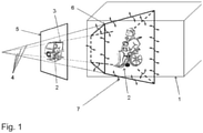
- the only figure shows schematically a cuboid for the depth image of an object (1) that was recorded with a stereo camera.
- the object consists of a wheelchair user (2) and a car (3), e.g. a van. Since the wheelchair user (2) is directly in front of the car (3), i.e. there is no spatial separation between the two, both are identified or clustered as a single object from a 3D image of the stereo camera.
- a 2D image (5) is also included, which was preferably recorded by one of the two stereo camera sensors.
- the 2D image (5) shown is in the virtual image plane of the recording camera and here includes the wheelchair user (2) and at least partially the car (3).
- the image area of the 2D image that corresponds to the determined depth image of the object (1) can be determined in advance, so that only this image area is analyzed further in the 2D image.
- An image processing method known per se in two-dimensional image data is suitable for analysis in the 2D image, in particular edge detection, intensity or color value analysis, segmentation and/or pattern recognition.
- the image processing method or methods are advantageously followed by object formation and classification based on the 2D image data.
- the object classification from the 2D image shows that at least a first object can be classified as “wheelchair user”, possibly a second object can also be classified as “car” or “van”. It is possible that the second object cannot be classified here because the car is not fully included in the 2D image and is also partially covered by the wheelchair user. However, that is not crucial at this point.
- a placeholder (6) for the depth image is now created for the object successfully classified as "wheelchair user".
- a frustum (6) is spanned from the size of the object "wheelchair user” classified in the 2D image (5) and the distance resulting from the depth image and the class-specific depth of the object.
- This frustum (6) also takes into account tolerances and deviations caused by the accuracy of the 3D acquisition, noise in the 2D image and/or scattering of typical object dimensions of a class around average object dimensions.
- the frustum (6) thus fulfills the function of a placeholder.
- typical spatial dimensions of a "wheelchair user” are to be assumed.
- the frustum can be determined as a projection into the spatial field of view (4) of the stereo camera.
- the frustum (6) has the three-dimensional shape of a truncated pyramid shown schematically in the figure.
- this offers the advantage that the wheelchair user (2) is reliably detected as an independent object in the depicted scene and the car or van (3) is then also detected in a comparable way.
- the detection from the depth image of this scene only supplies one object (1), which is too extensive for both of the object classes actually present and is in danger of not being able to be classified at all.
- a protective measure by a driver assistance system in favor of the wheelchair user (2) may not be implemented because she is not recognized as a "wheelchair user".
Description
Die Erfindung betrifft ein Verfahren und eine Vorrichtung zur Objekterkennung aus tiefenaufgelösten Bilddaten, welches insbesondere in einem Fahrerassistenzsystem mit einer 3D- oder Stereokamera zum Einsatz kommt.The invention relates to a method and a device for object recognition from depth-resolved image data, which is used in particular in a driver assistance system with a 3D or stereo camera.
Fahrerassistenzsysteme mit einer Fahrzeugkamera finden zunehmend Verbreitung. Neben Monokameras werden hierbei auch 3D-Kameras bzw. Stereokameras eingesetzt. Bei Stereokameras ergibt sich aus der Bildinformation beider Kamerasensoren die Möglichkeit, pro Pixel eine Tiefeninformation zu errechnen. Ein daraus resultierendes Tiefenbild kann anschließend geclustert werden, um erhabene Objekte vor der Kamera zu detektieren.Driver assistance systems with a vehicle camera are becoming increasingly widespread. In addition to mono cameras, 3D cameras or stereo cameras are also used here. With stereo cameras, the image information from both camera sensors makes it possible to calculate depth information per pixel. A resulting depth image can then be clustered to detect raised objects in front of the camera.
Diese Verwerfungsklasse kann unter Umständen relevante Objekte enthalten, z.B. aufgrund fehlerbehafteter Erfassung bzw. Auswertung der Umfeldsensorik, die dann für Fahrerassistenzfunktionen nicht berücksichtigt werden, da die Objekte der Verwerfungsklasse ja verworfen werden.Under certain circumstances, this rejection class can contain relevant objects, e.g. due to faulty detection or evaluation of the environment sensors, which are then not taken into account for driver assistance functions, since the objects of the rejection class are rejected.
Die Druckschrift
Aufgabe der vorliegenden Erfindung ist es, die genannten Schwierigkeiten bzw. Nachteile, die sich aus dem Stand der Technik ergeben, zu überwinden und ein verbessertes Verfahren zur Objekterkennung aus tiefenaufgelösten Bilddaten anzugeben. Ein Ausgangspunkt der vorliegenden Erfindung ist, dass z.B. zwei räumlich ineinander übergehende Objekte rein aus der Tiefeninformation nicht als zwei separate Objekte erkannt werden, sondern ein einzelnes größeres Objekt erkannt wird. Weder anhand seiner dreidimensionalen Form noch anhand seiner Abmessungen wird dieses größere (zusammengesetzte) Objekt richtig klassifiziert werden können.The object of the present invention is to overcome the difficulties and disadvantages mentioned, which result from the prior art, and to specify an improved method for object recognition from depth-resolved image data. A starting point of the present invention is that, for example, two objects that spatially merge into one another are not recognized as two separate objects purely from the depth information, but rather a single, larger object is recognized. Neither its three-dimensional form nor its dimensions will allow this larger (composite) object to be properly classified.
Ein erfindungsgemäßes Verfahren zur Objekterkennung wird im Anspruch 1 definiert.A method for object recognition according to the invention is defined in claim 1.
Die 3D-Kamera kann insbesondere eine Stereokamera sein und das 2D-Bild kann vorzugsweise mit einem der beiden Stereokamerasensoren aufgenommen werden. Alternative 3D-Kameras sind z.B. Time-of-Flight-Kameras, insbesondere ein Photonenmischdetektor (Photonic Mixer Device, PMD).The 3D camera can in particular be a stereo camera and the 2D image can preferably be recorded with one of the two stereo camera sensors. Alternative 3D cameras are e.g. time-of-flight cameras, in particular a photonic mixer device (PMD).
Mit der 3D-Kamera kann ein dreidimensionales Bild bzw. ein tiefenaufgelöstes Bild bzw. Tiefenbild aufgenommen werden. Aus diesen tiefenaufgelösten Bilddaten (Tiefenbild) können dreidimensional zusammenhängende Objekte gebildet werden.A three-dimensional image or a depth-resolved image or depth image can be recorded with the 3D camera. From this depth-resolved image data (depth image), three-dimensional coherent objects can be formed.
Da die räumliche Position und Ausdehnung der gebildeten Objekte bekannt ist, kann insbesondere unter Kenntnis der Abbildungseigenschaften des monokularen Kamerasensors der Bereich im 2D-Bild bestimmt werden, in dem die gebildeten Objekte abgebildet werden. Zumindest dieser Bereich des 2D-Bildes wird ausgewertet und dort aufgefundene (2D-)Objekte werden klassifiziert. Die Auswertung im 2D-Bild umfasst bevorzugt eine Kantenerkennung, Intensitäts- bzw. Farbwertanalyse, Segmentierung und/oder Mustererkennung. Hieran kann sich vorteilhaft eine 2D-Objektbildung anschließen. Bei der Klassifizierung werden Objekte aus den 2D-Bilddaten unterschiedlichen Klassen von Objekten zugeordnet. Diese Zuordnung kann auch über Wahrscheinlichkeitsangaben erfolgen. Einer Objektklasse wie z.B. "Kleinstwagen", "Kleinwagen", "mittelgroßer Wagen", "Großer Wagen" "SUV", "Van", "Motorrad", "Radfahrer", "erwachsener Fußgänger", "Kind", "Rollstuhlfahrer" sind typische mittlere 3D-Abmessungen und ggfs. Formen zugeordnet. Unter Berücksichtigung dieser klassenspezifischen Eigenschaften bzw. 3D-Abmessungen, die sich aus dem 2D-Bild ergeben, kann schließlich das gebildete (dreidimensionale) Objekt in mindestens zwei einzelne Objekte geteilt werden. Sofern die klassenspezifischen Eigenschaften mit dem gebildeten Objekt hingegen hinreichend übereinstimmen, kann das gebildete Objekt verifiziert werden.Since the spatial position and extension of the formed objects is known, the region in the 2D image in which the formed objects are imaged can be determined, in particular by knowing the imaging properties of the monocular camera sensor. At least this area of the 2D image is evaluated and (2D) objects found there are classified. The evaluation in the 2D image preferably includes edge recognition, intensity or color value analysis, segmentation and/or pattern recognition. This can advantageously be followed by a 2D object formation. In the Classification, objects from the 2D image data are assigned to different classes of objects. This assignment can also be made using probability statements. An object class such as "Microcar", "Small Car", "Medium Car", "Large Car", "SUV", "Van", "Motorcycle", "Cyclist", "Adult Pedestrian", "Child", "Wheelchair User". typical mean 3D dimensions and, if necessary, shapes assigned. Taking into account these class-specific properties or 3D dimensions, which result from the 2D image, the (three-dimensional) object that is formed can finally be divided into at least two individual objects. On the other hand, if the class-specific properties sufficiently match the formed object, the formed object can be verified.
Bevorzugt stellen das Tiefenbild und das 2D-Bild zumindest teilweise überlappende Bereiche einer Fahrzeugumgebung dar. Dies ist insbesondere bei einer Fahrzeugstereokamera zur Umgebungsüberwachung der Fall. Tiefen- und 2D-Bild stellen vorzugsweise Daten für mindestens eine Fahrerassistenzfunktion bereit. Bekannte kamerabasierte Fahrerassistenzfunktionen sind z.B. eine Spurverlassenswarnung (LDW, Lane Departure Warning), eine Spurhalteunterstützung (LKA/LKS, Lane Keeping Assistance/System), eine Verkehrszeichenerkennung (TSR, Traffic Sign Recognition), ein Geschwindigkeitsbegrenzungsempfehlung (SLA, Speed Limit Assist), eine automatische Fernlichtsteuerung (IHC, Intelligent Headlamp Control), eine Kollisionswarnung (FCW, Forward Collision Warning), eine Niederschlags-/Regen- und/oder Taglichterkennung, eine automatische Längsregelung (ACC, Adaptive Cruise Control), eine Einparkunterstützung sowie automatische Notbrems- bzw. Notlenksysteme (EBA, Emergency Brake Assist oder ESA, Emergency Steering Assist).The depth image and the 2D image preferably represent at least partially overlapping areas of a vehicle environment. This is the case in particular with a vehicle stereo camera for monitoring the environment. Depth and 2D image preferably provide data for at least one driver assistance function. Known camera-based driver assistance functions are, for example, a lane departure warning (LDW, Lane Departure Warning), lane keeping support (LKA/LKS, Lane Keeping Assistance/System), traffic sign recognition (TSR, Traffic Sign Recognition), a speed limit recommendation (SLA, Speed Limit Assist), a automatic high beam control (IHC, Intelligent Headlamp Control), a collision warning (FCW, Forward Collision Warning), precipitation/rain and/or daylight detection, automatic longitudinal control (ACC, Adaptive Cruise Control), parking assistance and automatic emergency braking or Emergency steering systems (EBA, Emergency Brake Assist or ESA, Emergency Steering Assist).
In einer bevorzugten Ausführungsform wird mindestens ein 3D-Platzhalter entsprechend des Ergebnisses der Klassifizierung des oder der Objekte im 2D-Bild bestimmt und als Platzhalter für dieses Objekt im Tiefenbild berücksichtigt.In a preferred embodiment, at least one 3D placeholder is determined according to the result of the classification of the object or objects in the 2D image and taken into account as a placeholder for this object in the depth image.
Vorteilhaft wird als 3D-Platzhalter ein Frustum verwendet. Das Frustum wird aus den typischen dreidimensionalen Abmessungen des im 2D-Bild klassifizierten Objekts und der aus dem Tiefenbild resultierenden Entfernung gebildet. Als dreidimensionale Form des Frustums kann entsprechend einer Fluchtpunktperspektive die eines Pyramidenstumpfs verwendet werden.A frustum is advantageously used as a 3D placeholder. The frustum is formed from the typical three-dimensional dimensions of the object classified in the 2D image and the distance resulting from the depth image. A truncated pyramid can be used as the three-dimensional form of the frustum, corresponding to a vanishing point perspective.
Gemäß einer bevorzugten Ausführungsform kann der 3D-Platzhalter Toleranzen berücksichtigen, die sich aus der 3D- und/oder 2D-Bilderfassung und -auswertung ergeben. So ist die dreidimensionale Positionsbestimmung fehlerbehaftet und z.B. Rauschen im 2D-Bild kann zu einer Ungenauigkeit in der Klassifizierung führen.According to a preferred embodiment, the 3D placeholder can take into account tolerances that result from the 3D and/or 2D image acquisition and evaluation. The three-dimensional position determination is subject to errors and noise in the 2D image, for example, can lead to inaccurate classification.
Vorteilhaft kann der 3D-Platzhalter die Streuung von 3D-Abmessungen innerhalb einer Klasse von Objekten berücksichtigen. Die Höhe kann bei der Klasse "erwachsener Fußgänger" beispielsweise zwischen 1,50 und 2,30 Metern um einen Mittelwert von z.B. 1,70 Meter streuen.Advantageously, the 3D placeholder can account for the spread of 3D dimensions within a class of objects. In the "adult pedestrian" class, for example, the height can vary between 1.50 and 2.30 meters around an average value of e.g. 1.70 meters.
Vorzugsweise wird der Bereich des 3D-Platzhalters aus dem mindestens einen Objekt herausgetrennt, welches aus dem Tiefenbild gebildet wurde.The area of the 3D placeholder is preferably separated out from the at least one object that was formed from the depth image.
In einer bevorzugten Ausführungsform werden unter Berücksichtigung des mindestens einen 3D-Platzhalters aus dem Tiefenbild erneut Objekte gebildet, wobei eine Objektbildung über die Grenzen des 3D-Platzhalters hinaus erschwert wird. Toleranzen und Streuungen können hierbei durch unterschiedliche "Erschwernisse" berücksichtigt werden.In a preferred embodiment, objects are formed again from the depth image, taking into account the at least one 3D placeholder, object formation beyond the limits of the 3D placeholder being made more difficult. Tolerances and scattering can be taken into account by different "difficulties".
Vorzugsweise wird der 3D-Platzhalter mit dem aus dem Tiefenbild gebildeten mindestens einen Objekt verglichen und bei annähernder Übereinstimmung der entsprechenden Raumvolumina wird keine Teilung dieses Objekts vorgenommen. Das gebildete Objekt wird hierdurch verifiziert.The 3D placeholder is preferably compared with the at least one object formed from the depth image and, if the corresponding spatial volumes are approximately the same, this object is not divided. The object formed is thereby verified.
Die Erfindung betrifft zudem eine Vorrichtung zur Objekterkennung gemäß Anspruch 10.The invention also relates to a device for object recognition according to
Im Folgenden wird die Erfindung anhand von Ausführungsbeispielen und einer Figur näher erläutert.The invention is explained in more detail below using exemplary embodiments and a figure.
Die einzige Figur zeigt schematisch einen Quader für das Tiefenbild eines Objekts (1), das mit einer Stereokamera aufgenommen wurde. Das Objekt besteht aus einer Rollstuhlfahrerin (2) und einem Pkw (3), z.B. einem Van. Da sich die Rollstuhlfahrerin (2) direkt vor dem Pkw (3) befindet, also keine räumliche Trennung zwischen diesen beiden vorliegt, werden beide als ein einzelnes Objekt aus einem 3D-Bild der Stereokamera ermittelt bzw. geclustert.The only figure shows schematically a cuboid for the depth image of an object (1) that was recorded with a stereo camera. The object consists of a wheelchair user (2) and a car (3), e.g. a van. Since the wheelchair user (2) is directly in front of the car (3), i.e. there is no spatial separation between the two, both are identified or clustered as a single object from a 3D image of the stereo camera.
In der Darstellung nach
An das bzw. die Bildverarbeitungsverfahren schließt sich vorteilhaft eine Objektbildung und -klassifizierung basierend auf den 2D-Bilddaten an. Die Objektklassifizierung aus dem 2D-Bild ergibt vorliegend, dass zumindest ein erstes Objekt als "Rollstuhlfahrer" klassifiziert werden kann, möglicherweise kann auch ein zweites Objekt als "Pkw" oder "Van" klassifiziert werden. Möglicherweise kann das zweite Objekt hier nicht klassifiziert werden, da der Pkw nicht vollständig im 2D-Bild enthalten und zudem teilweise durch die Rollstuhlfahrerin verdeckt ist. Das ist jedoch nicht weiter entscheidend an dieser Stelle.The image processing method or methods are advantageously followed by object formation and classification based on the 2D image data. In the present case, the object classification from the 2D image shows that at least a first object can be classified as “wheelchair user”, possibly a second object can also be classified as “car” or “van”. It is possible that the second object cannot be classified here because the car is not fully included in the 2D image and is also partially covered by the wheelchair user. However, that is not crucial at this point.
Zu dem erfolgreich als "Rollstuhlfahrer" klassifizierten Objekt wird nun ein Platzhalter (6) für das Tiefenbild gebildet. Dazu wird ein aus der Größe des im 2D-Bild (5) klassifizierten Objektes "Rollstuhlfahrer" und der aus dem Tiefenbild resultierenden Entfernung und der klassenspezifischen Tiefe des Objektes ein Frustum (6) aufgespannt. Dieses Frustum (6) berücksichtigt außerdem Toleranzen und Abweichungen, die durch die Genauigkeit der 3D-Erfassung, Rauschen im 2D-Bild und/oder Streuungen typischer Objektabmessungen einer Klasse um mittlere Objektabmessungen berücksichtigen. Das Frustum (6) erfüllt dadurch die Funktion eines Platzhalters. Dazu sind typische räumliche Abmessungen eines "Rollstuhlfahrers" anzunehmen. Mit Hilfe dieser Abmessungen und des aus dem Tiefenbild für jeden Pixel bekannten Abstands zur Kamera kann das Frustum als Projektion in das räumliche Sichtfeld (4) der Stereokamera ermittelt werden. Das Frustum (6) hat bei einer Fluchtpunktperspektive des Sichtfelds (4) die in der Figur schematisch dargestellte dreidimensionale Form eines Pyramidenstumpfs.A placeholder (6) for the depth image is now created for the object successfully classified as "wheelchair user". For this purpose, a frustum (6) is spanned from the size of the object "wheelchair user" classified in the 2D image (5) and the distance resulting from the depth image and the class-specific depth of the object. This frustum (6) also takes into account tolerances and deviations caused by the accuracy of the 3D acquisition, noise in the 2D image and/or scattering of typical object dimensions of a class around average object dimensions. The frustum (6) thus fulfills the function of a placeholder. For this purpose, typical spatial dimensions of a "wheelchair user" are to be assumed. With the help of these dimensions and the distance to the camera known from the depth image for each pixel, the frustum can be determined as a projection into the spatial field of view (4) of the stereo camera. In a vanishing point perspective of the field of view (4), the frustum (6) has the three-dimensional shape of a truncated pyramid shown schematically in the figure.
Mithilfe des Frustums (6) werden anschließend im Raum Verbindungen nach Außerhalb des Frustums fürs Clustering parametrierbar erschwert (7). Dadurch können Objekte, die sich im Tiefenbild nur schwer trennen lassen, im Raum sauber getrennt werden. Dies ist wie hier dargestellt der Fall für die Rollstuhlfahrerin (2) und den Pkw (3), in gleicher Weise gilt das auch für die Auflösung (Objektsplitting) von Gruppen von Fußgängern, einer an eine Hauswand gelehnte Person, sehr dicht aneinander geparkten Fahrzeugen oder anderen räumlich ineinander übergehenden Objekten.With the help of the frustum (6), connections to outside the frustum for clustering are then made more difficult in the room (7). This allows objects that are difficult to separate in the depth image to be cleanly separated in space. As shown here, this is the case for the wheelchair user (2) and the car (3), and it applies in the same way also for the dissolution (object splitting) of groups of pedestrians, a person leaning against a house wall, vehicles parked very close together or other spatially merging objects.
Dies bietet für Fahrerassistenzfunktionen, die auf den erkannten Objekten basieren, den Vorteil, dass bei der abgebildeten Szene die Rollstuhlfahrerin (2) als eigenständiges Objekt zuverlässig erkannt wird und anschließend in vergleichbarer Weise auch der Pkw bzw. Van (3) erkannt wird.For driver assistance functions based on the detected objects, this offers the advantage that the wheelchair user (2) is reliably detected as an independent object in the depicted scene and the car or van (3) is then also detected in a comparable way.
Dagegen liefert die Erkennung aus dem Tiefenbild dieser Szene nur ein Objekt (1), welches zu ausgedehnt für beide der tatsächlich vorhandenen Objektklassen ist und in der Gefahr steht gar nicht klassifiziert werden zu können. Eine Schutzmaßnahme eines Fahrerassistenzsystems zugunsten der Rollstuhlfahrerin (2) unterbleibt möglicherweise, weil diese gar nicht als "Rollstuhlfahrer" erkannt wird.In contrast, the detection from the depth image of this scene only supplies one object (1), which is too extensive for both of the object classes actually present and is in danger of not being able to be classified at all. A protective measure by a driver assistance system in favor of the wheelchair user (2) may not be implemented because she is not recognized as a "wheelchair user".
- 11
- Aus dem Tiefenbild gebildetes ObjektObject formed from the depth image
- 22
- Rollstuhlfahrerinwheelchair user
- 33
- Pkwcar
- 44
- Sichtfeldfield of view
- 55
- 2D-Bild2D image
- 66
- Platzhalter/FrustumPlaceholder/Frustum
- 77
- Erschwerte Verbindung beim Clustering von außen in das Frustum bzw. vom Frustum nach außenDifficult connection when clustering from the outside into the frustum or from the frustum to the outside
Claims (10)
- Method for object recognition, comprising the steps of:- forming a three-dimensionally contiguous object from a three-dimensional image of a 3D camera,
= evaluating and classifying one or more objects (2, 3) in an image region of a 2D image (5) which corresponds to the formed three-dimensionally contiguous object in the three-dimensional image (1),- assigning typical class-specific 3D dimensions on the basis of the classification of the object or objects (2, 3) in the 2D image,- dividing the three-dimensionally contiguous object (1) formed from the three-dimensional image into a plurality of individual three-dimensional objects (2; 3) taking into account the class-specific 3D dimensions if the formed three-dimensionally contiguous object is too extended for the assigned class-specific 3D dimensions of the classified object or objects (2, 3). - Method according to Claim 1, wherein the three-dimensional image is captured by means of a 3D camera, in particular a vehicle stereo camera of a driver assistance system, and the 2D image (5) is captured by means of a monocular camera sensor of a driver assistance system and they represent at least partially overlapping regions of a surrounding area of the vehicle.
- Method according to Claim 2, wherein the monocular camera sensor is one of the two camera sensors of a vehicle stereo camera.
- Method according to one of the preceding claims, wherein at least one 3D placeholder (6) corresponding to the result of the classification of the object or objects (2, 3) in the 2D image (5) is determined and taken into account as a placeholder for this object in the three-dimensional image.
- Method according to one of the preceding claims, wherein the 3D placeholder (6) is a frustum.
- Method according to one of the preceding claims, wherein the 3D placeholder (6) takes into account tolerances resulting from the 3D and/or 2D image capturing and evaluation.
- Method according to one of the preceding claims, wherein the 3D placeholder (6) takes into account the dispersion of 3D dimensions within a class of objects.
- Method according to one of the preceding claims, wherein the 3D placeholder (6) is compared with the three-dimensionally contiguous object (1) formed from the three-dimensional image and, if there is an approximate match, the three-dimensionally contiguous object is not divided.
- Method according to one of the preceding claims, wherein objects are again formed from the three-dimensional image taking into account the at least one 3D placeholder (6), wherein object forming is made more difficult beyond the limits of the 3D placeholder (6).
- Apparatus for object recognition in a vehicle vicinity, comprisinga 3D camera, which is configured to capture a three-dimensional image,a first object-forming unit, which is configured to form at least one three-dimensionally contiguous object from the three-dimensional image,a camera sensor, which is configured to record a 2D image (5),a 2D image evaluation and classification unit, which is configured toclassify one or more objects (2, 3) in an image region of the 2D image (5) which corresponds to the at least one formed three-dimensionally contiguous object in the three-dimensional image (1),assign typical class-specific 3D dimensions on the basis of the classified object or objects (2, 3) in the 2D image, andan object dividing unit, which is configured to divide the three-dimensionally contiguous object (1) formed from the three-dimensional image into a plurality of individual three-dimensional objects (2; 3) taking into account the typical class-specific 3D dimensions of the classified object or objects (2, 3) if the formed three-dimensionally contiguous object is too extended for the assigned typical class-specific 3D dimensions of the object or objects (2, 3).
Applications Claiming Priority (2)
| Application Number | Priority Date | Filing Date | Title |
|---|---|---|---|
| DE102013217915.4A DE102013217915A1 (en) | 2013-09-09 | 2013-09-09 | Method and device for object recognition from depth-resolved image data |
| PCT/DE2014/200443 WO2015032399A1 (en) | 2013-09-09 | 2014-09-04 | Method and device for detecting objects from depth-resolved image data |
Publications (2)
| Publication Number | Publication Date |
|---|---|
| EP3044727A1 EP3044727A1 (en) | 2016-07-20 |
| EP3044727B1 true EP3044727B1 (en) | 2022-01-19 |
Family
ID=51627909
Family Applications (1)
| Application Number | Title | Priority Date | Filing Date |
|---|---|---|---|
| EP14777256.0A Active EP3044727B1 (en) | 2013-09-09 | 2014-09-04 | Method and device for detecting objects from depth-resolved image data |
Country Status (5)
| Country | Link |
|---|---|
| US (1) | US9870513B2 (en) |
| EP (1) | EP3044727B1 (en) |
| JP (1) | JP6571658B2 (en) |
| DE (2) | DE102013217915A1 (en) |
| WO (1) | WO2015032399A1 (en) |
Families Citing this family (8)
| Publication number | Priority date | Publication date | Assignee | Title |
|---|---|---|---|---|
| DE102015010514B4 (en) * | 2015-08-13 | 2019-06-13 | Audi Ag | A method of determining map information for a map data set of a navigation environment and computing device |
| US10466714B2 (en) * | 2016-09-01 | 2019-11-05 | Ford Global Technologies, Llc | Depth map estimation with stereo images |
| KR101907883B1 (en) * | 2017-05-10 | 2018-10-16 | 국방과학연구소 | Object detection and classification method |
| DE102018209388A1 (en) * | 2018-06-13 | 2019-12-19 | Robert Bosch Gmbh | Detection of driving-relevant situations at a greater distance |
| ES2882402T3 (en) | 2018-07-09 | 2021-12-01 | Argo Ai Gmbh | Method for estimating a relative position of an object in the environment of a vehicle unit and electronic control unit for a vehicle and vehicle |
| US11514594B2 (en) | 2019-10-30 | 2022-11-29 | Vergence Automation, Inc. | Composite imaging systems using a focal plane array with in-pixel analog storage elements |
| US11789155B2 (en) | 2019-12-23 | 2023-10-17 | Zoox, Inc. | Pedestrian object detection training |
| US11462041B2 (en) * | 2019-12-23 | 2022-10-04 | Zoox, Inc. | Pedestrians with objects |
Citations (1)
| Publication number | Priority date | Publication date | Assignee | Title |
|---|---|---|---|---|
| US20070183669A1 (en) * | 2004-08-14 | 2007-08-09 | Yuri Owechko | Multi-view cognitive swarm for object recognition and 3D tracking |
Family Cites Families (12)
| Publication number | Priority date | Publication date | Assignee | Title |
|---|---|---|---|---|
| JPH05265547A (en) * | 1992-03-23 | 1993-10-15 | Fuji Heavy Ind Ltd | On-vehicle outside monitoring device |
| DE19926559A1 (en) * | 1999-06-11 | 2000-12-21 | Daimler Chrysler Ag | Method and device for detecting objects in the vicinity of a road vehicle up to a great distance |
| DE10336638A1 (en) | 2003-07-25 | 2005-02-10 | Robert Bosch Gmbh | Apparatus for classifying at least one object in a vehicle environment |
| ES2293268T5 (en) | 2003-07-25 | 2010-12-02 | Robert Bosch Gmbh | DEVICE FOR CLASSIFICATION OF AT LEAST ONE OBJECT IN THE ENVIRONMENT OF A VEHICLE. |
| EP1892149B1 (en) | 2006-08-24 | 2009-02-04 | Harman Becker Automotive Systems GmbH | Method for imaging the surrounding of a vehicle and system therefor |
| EP2026246A1 (en) * | 2007-08-03 | 2009-02-18 | Harman/Becker Automotive Systems GmbH | Method and apparatus for evaluating an image |
| US8401225B2 (en) * | 2011-01-31 | 2013-03-19 | Microsoft Corporation | Moving object segmentation using depth images |
| JP5693994B2 (en) * | 2011-02-16 | 2015-04-01 | 富士重工業株式会社 | Vehicle detection device |
| DE102011101246A1 (en) | 2011-05-11 | 2012-11-15 | Conti Temic Microelectronic Gmbh | REDUDENT OBJECT DETECTION FOR DRIVER ASSISTANCE SYSTEMS |
| JP5516998B2 (en) * | 2011-06-09 | 2014-06-11 | アイシン精機株式会社 | Image generation device |
| DE102012113009A1 (en) | 2012-12-21 | 2014-06-26 | Jenoptik Robot Gmbh | Method for automatically classifying moving vehicles |
| CN104217208B (en) * | 2013-06-03 | 2018-01-16 | 株式会社理光 | Object detection method and device |
-
2013
- 2013-09-09 DE DE102013217915.4A patent/DE102013217915A1/en not_active Withdrawn
-
2014
- 2014-09-04 DE DE112014002562.3T patent/DE112014002562A5/en active Pending
- 2014-09-04 JP JP2016539421A patent/JP6571658B2/en active Active
- 2014-09-04 WO PCT/DE2014/200443 patent/WO2015032399A1/en active Application Filing
- 2014-09-04 US US14/902,176 patent/US9870513B2/en active Active
- 2014-09-04 EP EP14777256.0A patent/EP3044727B1/en active Active
Patent Citations (1)
| Publication number | Priority date | Publication date | Assignee | Title |
|---|---|---|---|---|
| US20070183669A1 (en) * | 2004-08-14 | 2007-08-09 | Yuri Owechko | Multi-view cognitive swarm for object recognition and 3D tracking |
Non-Patent Citations (1)
| Title |
|---|
| STEPHEN GOULD: "Integrating Visual and Range Data for Robotic Object Detection", M2SFA2 2008: WORKSHOP ON MULTI-CAMERA AND MULTI-MODAL SENSOR FUSION, 1 January 2008 (2008-01-01), XP055041887, Retrieved from the Internet <URL:http://users.cecs.anu.edu.au/~sgould/papers/eccv08-vision3d.pdf> [retrieved on 20121023] * |
Also Published As
| Publication number | Publication date |
|---|---|
| US20160371549A1 (en) | 2016-12-22 |
| EP3044727A1 (en) | 2016-07-20 |
| JP2016530639A (en) | 2016-09-29 |
| DE112014002562A5 (en) | 2016-03-03 |
| JP6571658B2 (en) | 2019-09-04 |
| US9870513B2 (en) | 2018-01-16 |
| DE102013217915A1 (en) | 2015-03-12 |
| WO2015032399A1 (en) | 2015-03-12 |
Similar Documents
| Publication | Publication Date | Title |
|---|---|---|
| EP3044727B1 (en) | Method and device for detecting objects from depth-resolved image data | |
| EP3292510B1 (en) | Method and apparatus for detecting and assessing road reflections | |
| WO2019174682A1 (en) | Method and device for detecting and evaluating roadway conditions and weather-related environmental influences | |
| DE102017203838A1 (en) | Method and system for environment detection | |
| DE102018212655A1 (en) | Detection of the intention to move a pedestrian from camera images | |
| EP2150939B1 (en) | Method and device for determining the position of a road sign | |
| WO2016026568A1 (en) | Method and axle-counting device for contact-free axle counting of a vehicle and axle-counting system for road traffic | |
| DE112014007249T5 (en) | Image processing apparatus, vehicle display system, display apparatus, image processing method and image processing program | |
| DE102014201159A1 (en) | Method and device for classifying a behavior of a pedestrian when crossing a roadway of a vehicle and personal protection system of a vehicle | |
| DE112013001424T5 (en) | Object detection device | |
| DE102014207802B3 (en) | Method and system for proactively detecting an action of a road user | |
| DE10336638A1 (en) | Apparatus for classifying at least one object in a vehicle environment | |
| EP3053097A1 (en) | Method and apparatus for identifying road signs | |
| EP3631677A1 (en) | Method for detecting objects in an image of a camera | |
| WO2016177372A1 (en) | Method and device for detecting and evaluating environmental influences and road condition information in the vehicle surroundings | |
| DE102018100909A1 (en) | Method of reconstructing images of a scene taken by a multifocal camera system | |
| EP3078015B1 (en) | Method and device for generating an alert by means of two images of a vehicle environment obtained via cameras | |
| DE102012023060A1 (en) | Method for detecting moving object in surrounding region of motor vehicle e.g.passenger car, involves determining vector values within the respective interval values, such movable object is detected based on histogram | |
| WO2020020654A1 (en) | Method for operating a driver assistance system having two detection devices | |
| DE102011055441A1 (en) | Method for determining spacing between preceding and forthcoming motor cars by using mono camera in e.g. adaptive cruise control system, involves determining spacing between cars based on information about license plate number | |
| DE102013021840A1 (en) | Method for generating an environment model of a motor vehicle, driver assistance system and motor vehicle | |
| EP3520020B1 (en) | Road sign classification in a surrounding area of a motor vehicle | |
| EP2696310B1 (en) | Method for identifying the edge of a road | |
| DE102014218027A1 (en) | Devices for image acquisition in the field of a motor vehicle | |
| DE102018107212A1 (en) | A method for detecting a traffic area occupancy detection auxiliary element in a surrounding area of a motor vehicle, computer program product and vehicle guidance system |
Legal Events
| Date | Code | Title | Description |
|---|---|---|---|
| PUAI | Public reference made under article 153(3) epc to a published international application that has entered the european phase |
Free format text: ORIGINAL CODE: 0009012 |
|
| 17P | Request for examination filed |
Effective date: 20160411 |
|
| AK | Designated contracting states |
Kind code of ref document: A1 Designated state(s): AL AT BE BG CH CY CZ DE DK EE ES FI FR GB GR HR HU IE IS IT LI LT LU LV MC MK MT NL NO PL PT RO RS SE SI SK SM TR |
|
| AX | Request for extension of the european patent |
Extension state: BA ME |
|
| RIN1 | Information on inventor provided before grant (corrected) |
Inventor name: BACHMANN, ALEXANDER Inventor name: THIEL, ROBERT |
|
| DAX | Request for extension of the european patent (deleted) | ||
| STAA | Information on the status of an ep patent application or granted ep patent |
Free format text: STATUS: EXAMINATION IS IN PROGRESS |
|
| 17Q | First examination report despatched |
Effective date: 20190926 |
|
| STAA | Information on the status of an ep patent application or granted ep patent |
Free format text: STATUS: EXAMINATION IS IN PROGRESS |
|
| RAP1 | Party data changed (applicant data changed or rights of an application transferred) |
Owner name: CONTI TEMIC MICROELECTRONIC GMBH |
|
| GRAP | Despatch of communication of intention to grant a patent |
Free format text: ORIGINAL CODE: EPIDOSNIGR1 |
|
| STAA | Information on the status of an ep patent application or granted ep patent |
Free format text: STATUS: GRANT OF PATENT IS INTENDED |
|
| RIC1 | Information provided on ipc code assigned before grant |
Ipc: H04N 13/275 20180101ALI20210914BHEP Ipc: H04N 13/271 20180101ALI20210914BHEP Ipc: H04N 13/204 20180101ALI20210914BHEP Ipc: G06K 9/00 20060101AFI20210914BHEP |
|
| INTG | Intention to grant announced |
Effective date: 20211004 |
|
| GRAS | Grant fee paid |
Free format text: ORIGINAL CODE: EPIDOSNIGR3 |
|
| GRAA | (expected) grant |
Free format text: ORIGINAL CODE: 0009210 |
|
| STAA | Information on the status of an ep patent application or granted ep patent |
Free format text: STATUS: THE PATENT HAS BEEN GRANTED |
|
| AK | Designated contracting states |
Kind code of ref document: B1 Designated state(s): AL AT BE BG CH CY CZ DE DK EE ES FI FR GB GR HR HU IE IS IT LI LT LU LV MC MK MT NL NO PL PT RO RS SE SI SK SM TR |
|
| REG | Reference to a national code |
Ref country code: GB Ref legal event code: FG4D Free format text: NOT ENGLISH |
|
| REG | Reference to a national code |
Ref country code: CH Ref legal event code: EP |
|
| REG | Reference to a national code |
Ref country code: DE Ref legal event code: R096 Ref document number: 502014016087 Country of ref document: DE |
|
| REG | Reference to a national code |
Ref country code: AT Ref legal event code: REF Ref document number: 1464226 Country of ref document: AT Kind code of ref document: T Effective date: 20220215 |
|
| REG | Reference to a national code |
Ref country code: IE Ref legal event code: FG4D Free format text: LANGUAGE OF EP DOCUMENT: GERMAN |
|
| REG | Reference to a national code |
Ref country code: SE Ref legal event code: TRGR |
|
| REG | Reference to a national code |
Ref country code: LT Ref legal event code: MG9D |
|
| REG | Reference to a national code |
Ref country code: NL Ref legal event code: MP Effective date: 20220119 |
|
| REG | Reference to a national code |
Ref country code: DE Ref legal event code: R081 Ref document number: 502014016087 Country of ref document: DE Owner name: CONTINENTAL AUTONOMOUS MOBILITY GERMANY GMBH, DE Free format text: FORMER OWNER: CONTI TEMIC MICROELECTRONIC GMBH, 90411 NUERNBERG, DE |
|
| PG25 | Lapsed in a contracting state [announced via postgrant information from national office to epo] |
Ref country code: NL Free format text: LAPSE BECAUSE OF FAILURE TO SUBMIT A TRANSLATION OF THE DESCRIPTION OR TO PAY THE FEE WITHIN THE PRESCRIBED TIME-LIMIT Effective date: 20220119 |
|
| PG25 | Lapsed in a contracting state [announced via postgrant information from national office to epo] |
Ref country code: RS Free format text: LAPSE BECAUSE OF FAILURE TO SUBMIT A TRANSLATION OF THE DESCRIPTION OR TO PAY THE FEE WITHIN THE PRESCRIBED TIME-LIMIT Effective date: 20220119 Ref country code: PT Free format text: LAPSE BECAUSE OF FAILURE TO SUBMIT A TRANSLATION OF THE DESCRIPTION OR TO PAY THE FEE WITHIN THE PRESCRIBED TIME-LIMIT Effective date: 20220519 Ref country code: NO Free format text: LAPSE BECAUSE OF FAILURE TO SUBMIT A TRANSLATION OF THE DESCRIPTION OR TO PAY THE FEE WITHIN THE PRESCRIBED TIME-LIMIT Effective date: 20220419 Ref country code: LT Free format text: LAPSE BECAUSE OF FAILURE TO SUBMIT A TRANSLATION OF THE DESCRIPTION OR TO PAY THE FEE WITHIN THE PRESCRIBED TIME-LIMIT Effective date: 20220119 Ref country code: HR Free format text: LAPSE BECAUSE OF FAILURE TO SUBMIT A TRANSLATION OF THE DESCRIPTION OR TO PAY THE FEE WITHIN THE PRESCRIBED TIME-LIMIT Effective date: 20220119 Ref country code: ES Free format text: LAPSE BECAUSE OF FAILURE TO SUBMIT A TRANSLATION OF THE DESCRIPTION OR TO PAY THE FEE WITHIN THE PRESCRIBED TIME-LIMIT Effective date: 20220119 Ref country code: BG Free format text: LAPSE BECAUSE OF FAILURE TO SUBMIT A TRANSLATION OF THE DESCRIPTION OR TO PAY THE FEE WITHIN THE PRESCRIBED TIME-LIMIT Effective date: 20220419 |
|
| PG25 | Lapsed in a contracting state [announced via postgrant information from national office to epo] |
Ref country code: PL Free format text: LAPSE BECAUSE OF FAILURE TO SUBMIT A TRANSLATION OF THE DESCRIPTION OR TO PAY THE FEE WITHIN THE PRESCRIBED TIME-LIMIT Effective date: 20220119 Ref country code: LV Free format text: LAPSE BECAUSE OF FAILURE TO SUBMIT A TRANSLATION OF THE DESCRIPTION OR TO PAY THE FEE WITHIN THE PRESCRIBED TIME-LIMIT Effective date: 20220119 Ref country code: GR Free format text: LAPSE BECAUSE OF FAILURE TO SUBMIT A TRANSLATION OF THE DESCRIPTION OR TO PAY THE FEE WITHIN THE PRESCRIBED TIME-LIMIT Effective date: 20220420 Ref country code: FI Free format text: LAPSE BECAUSE OF FAILURE TO SUBMIT A TRANSLATION OF THE DESCRIPTION OR TO PAY THE FEE WITHIN THE PRESCRIBED TIME-LIMIT Effective date: 20220119 |
|
| PG25 | Lapsed in a contracting state [announced via postgrant information from national office to epo] |
Ref country code: IS Free format text: LAPSE BECAUSE OF FAILURE TO SUBMIT A TRANSLATION OF THE DESCRIPTION OR TO PAY THE FEE WITHIN THE PRESCRIBED TIME-LIMIT Effective date: 20220519 |
|
| REG | Reference to a national code |
Ref country code: DE Ref legal event code: R097 Ref document number: 502014016087 Country of ref document: DE |
|
| PG25 | Lapsed in a contracting state [announced via postgrant information from national office to epo] |
Ref country code: SM Free format text: LAPSE BECAUSE OF FAILURE TO SUBMIT A TRANSLATION OF THE DESCRIPTION OR TO PAY THE FEE WITHIN THE PRESCRIBED TIME-LIMIT Effective date: 20220119 Ref country code: SK Free format text: LAPSE BECAUSE OF FAILURE TO SUBMIT A TRANSLATION OF THE DESCRIPTION OR TO PAY THE FEE WITHIN THE PRESCRIBED TIME-LIMIT Effective date: 20220119 Ref country code: RO Free format text: LAPSE BECAUSE OF FAILURE TO SUBMIT A TRANSLATION OF THE DESCRIPTION OR TO PAY THE FEE WITHIN THE PRESCRIBED TIME-LIMIT Effective date: 20220119 Ref country code: EE Free format text: LAPSE BECAUSE OF FAILURE TO SUBMIT A TRANSLATION OF THE DESCRIPTION OR TO PAY THE FEE WITHIN THE PRESCRIBED TIME-LIMIT Effective date: 20220119 Ref country code: DK Free format text: LAPSE BECAUSE OF FAILURE TO SUBMIT A TRANSLATION OF THE DESCRIPTION OR TO PAY THE FEE WITHIN THE PRESCRIBED TIME-LIMIT Effective date: 20220119 Ref country code: CZ Free format text: LAPSE BECAUSE OF FAILURE TO SUBMIT A TRANSLATION OF THE DESCRIPTION OR TO PAY THE FEE WITHIN THE PRESCRIBED TIME-LIMIT Effective date: 20220119 |
|
| PLBE | No opposition filed within time limit |
Free format text: ORIGINAL CODE: 0009261 |
|
| REG | Reference to a national code |
Ref country code: DE Ref legal event code: R079 Ref document number: 502014016087 Country of ref document: DE Free format text: PREVIOUS MAIN CLASS: G06K0009000000 Ipc: G06V0010000000 |
|
| STAA | Information on the status of an ep patent application or granted ep patent |
Free format text: STATUS: NO OPPOSITION FILED WITHIN TIME LIMIT |
|
| PG25 | Lapsed in a contracting state [announced via postgrant information from national office to epo] |
Ref country code: AL Free format text: LAPSE BECAUSE OF FAILURE TO SUBMIT A TRANSLATION OF THE DESCRIPTION OR TO PAY THE FEE WITHIN THE PRESCRIBED TIME-LIMIT Effective date: 20220119 |
|
| 26N | No opposition filed |
Effective date: 20221020 |
|
| PG25 | Lapsed in a contracting state [announced via postgrant information from national office to epo] |
Ref country code: SI Free format text: LAPSE BECAUSE OF FAILURE TO SUBMIT A TRANSLATION OF THE DESCRIPTION OR TO PAY THE FEE WITHIN THE PRESCRIBED TIME-LIMIT Effective date: 20220119 |
|
| PG25 | Lapsed in a contracting state [announced via postgrant information from national office to epo] |
Ref country code: MC Free format text: LAPSE BECAUSE OF FAILURE TO SUBMIT A TRANSLATION OF THE DESCRIPTION OR TO PAY THE FEE WITHIN THE PRESCRIBED TIME-LIMIT Effective date: 20220119 |
|
| REG | Reference to a national code |
Ref country code: CH Ref legal event code: PL |
|
| GBPC | Gb: european patent ceased through non-payment of renewal fee |
Effective date: 20220904 |
|
| REG | Reference to a national code |
Ref country code: BE Ref legal event code: MM Effective date: 20220930 |
|
| P01 | Opt-out of the competence of the unified patent court (upc) registered |
Effective date: 20230522 |
|
| PG25 | Lapsed in a contracting state [announced via postgrant information from national office to epo] |
Ref country code: LU Free format text: LAPSE BECAUSE OF NON-PAYMENT OF DUE FEES Effective date: 20220904 |
|
| PG25 | Lapsed in a contracting state [announced via postgrant information from national office to epo] |
Ref country code: LI Free format text: LAPSE BECAUSE OF NON-PAYMENT OF DUE FEES Effective date: 20220930 Ref country code: IT Free format text: LAPSE BECAUSE OF FAILURE TO SUBMIT A TRANSLATION OF THE DESCRIPTION OR TO PAY THE FEE WITHIN THE PRESCRIBED TIME-LIMIT Effective date: 20220119 Ref country code: IE Free format text: LAPSE BECAUSE OF NON-PAYMENT OF DUE FEES Effective date: 20220904 Ref country code: CH Free format text: LAPSE BECAUSE OF NON-PAYMENT OF DUE FEES Effective date: 20220930 |
|
| PG25 | Lapsed in a contracting state [announced via postgrant information from national office to epo] |
Ref country code: BE Free format text: LAPSE BECAUSE OF NON-PAYMENT OF DUE FEES Effective date: 20220930 |
|
| PG25 | Lapsed in a contracting state [announced via postgrant information from national office to epo] |
Ref country code: GB Free format text: LAPSE BECAUSE OF NON-PAYMENT OF DUE FEES Effective date: 20220904 |
|
| REG | Reference to a national code |
Ref country code: AT Ref legal event code: MM01 Ref document number: 1464226 Country of ref document: AT Kind code of ref document: T Effective date: 20220904 |
|
| PGFP | Annual fee paid to national office [announced via postgrant information from national office to epo] |
Ref country code: SE Payment date: 20230920 Year of fee payment: 10 Ref country code: FR Payment date: 20230928 Year of fee payment: 10 Ref country code: DE Payment date: 20230930 Year of fee payment: 10 |
|
| PG25 | Lapsed in a contracting state [announced via postgrant information from national office to epo] |
Ref country code: AT Free format text: LAPSE BECAUSE OF NON-PAYMENT OF DUE FEES Effective date: 20220904 |
|
| PG25 | Lapsed in a contracting state [announced via postgrant information from national office to epo] |
Ref country code: HU Free format text: LAPSE BECAUSE OF FAILURE TO SUBMIT A TRANSLATION OF THE DESCRIPTION OR TO PAY THE FEE WITHIN THE PRESCRIBED TIME-LIMIT; INVALID AB INITIO Effective date: 20140904 |