EP3182193A1 - Optisches system - Google Patents
Optisches system Download PDFInfo
- Publication number
- EP3182193A1 EP3182193A1 EP16203638.8A EP16203638A EP3182193A1 EP 3182193 A1 EP3182193 A1 EP 3182193A1 EP 16203638 A EP16203638 A EP 16203638A EP 3182193 A1 EP3182193 A1 EP 3182193A1
- Authority
- EP
- European Patent Office
- Prior art keywords
- mirror
- rotation
- axis
- auxiliary beam
- signal
- Prior art date
- Legal status (The legal status is an assumption and is not a legal conclusion. Google has not performed a legal analysis and makes no representation as to the accuracy of the status listed.)
- Granted
Links
Images

Classifications
-
- G—PHYSICS
- G02—OPTICS
- G02B—OPTICAL ELEMENTS, SYSTEMS OR APPARATUS
- G02B27/00—Optical systems or apparatus not provided for by any of the groups G02B1/00 - G02B26/00, G02B30/00
- G02B27/62—Optical apparatus specially adapted for adjusting optical elements during the assembly of optical systems
-
- G—PHYSICS
- G01—MEASURING; TESTING
- G01B—MEASURING LENGTH, THICKNESS OR SIMILAR LINEAR DIMENSIONS; MEASURING ANGLES; MEASURING AREAS; MEASURING IRREGULARITIES OF SURFACES OR CONTOURS
- G01B11/00—Measuring arrangements characterised by the use of optical techniques
- G01B11/26—Measuring arrangements characterised by the use of optical techniques for measuring angles or tapers; for testing the alignment of axes
- G01B11/27—Measuring arrangements characterised by the use of optical techniques for measuring angles or tapers; for testing the alignment of axes for testing the alignment of axes
-
- G—PHYSICS
- G01—MEASURING; TESTING
- G01C—MEASURING DISTANCES, LEVELS OR BEARINGS; SURVEYING; NAVIGATION; GYROSCOPIC INSTRUMENTS; PHOTOGRAMMETRY OR VIDEOGRAMMETRY
- G01C15/00—Surveying instruments or accessories not provided for in groups G01C1/00 - G01C13/00
-
- G—PHYSICS
- G02—OPTICS
- G02B—OPTICAL ELEMENTS, SYSTEMS OR APPARATUS
- G02B27/00—Optical systems or apparatus not provided for by any of the groups G02B1/00 - G02B26/00, G02B30/00
- G02B27/30—Collimators
Definitions
- the invention relates to an optical system. Furthermore, the invention relates to a method for adjusting an optical beam, in particular a signal beam, wherein preferably such an optical system is used. With the optical system according to the invention and the method according to the invention, in particular a signal beam can be spatially stabilized, in particular in angle and position.
- an optical beam is guided over a rotatable arrangement, the beam undergoes a rotation about the instantaneous real mechanical axis of rotation.
- a rotatable arrangement may in particular be a Coudé beam path.
- the optical beam may be a laser beam or an imaging beam.
- the beam To stabilize an image in such a rotating system or to stabilize a rotationally symmetric beam stationary, the beam must be adjusted exactly to the real mechanical axis of rotation. In addition, the beam must not leave said axis of rotation during the rotation. In existing optical systems, these requirements can not or only partially be met.
- an optical system comprising a signal input, a signal output, an auxiliary light source and a rotation system.
- the Signal input is a signal beam recordable.
- the signal beam can be output.
- the signal beam may be an imaging beam.
- the signal beam may be a high-energy beam, in particular a laser beam.
- the auxiliary light source an auxiliary light beam can be emitted. It is provided that the auxiliary light beam is synchronous in angle and position to the signal beam. Alternatively, the auxiliary light beam can be coupled out of the signal beam.
- the rotation system is rotatable about an axis of rotation and has a signal output mirror and a reference mirror.
- the optical system has an axis coupling mirror.
- the signal beam and the auxiliary beam can be coupled into the rotation system.
- the signal output mirror With the signal output mirror in turn, the signal beam from the rotation system can be decoupled. It is particularly advantageously provided that the signal beam can be conducted directly from the signal output mirror to the signal output. For this purpose, advantageously no influence on the signal beam takes place.
- the axis of rotation intersects the axis coupling mirror, the signal output mirror and the reference mirror.
- the signal beam can be directed from the signal input via the axis coupling mirror to the signal output mirror.
- the auxiliary beam in turn can be steered to the reference mirror via the axis coupling mirror and through the axis coupling-out mirror.
- the auxiliary beam is at least partially mannreflektierbar to a reflection auxiliary beam.
- the auxiliary reflection beam passes through the axis output mirror in particular and back to the auxiliary light source via the axis coupling mirror.
- the optical system comprises an angle sensor.
- an angular deviation between the auxiliary beam and the reflection auxiliary beam can be detected. It will be appreciated that if the rotation system does not rotate, such angular deviation will only be present if the reference mirror is set incorrectly. Thus, by tilting the reference mirror, the angular deviation can be influenced. Should there be an angular deviation in a rotating rotation system, the signal beam and the auxiliary beam are not aligned with the axis of rotation. Thus, the angle deviation can be influenced by tilting the axis coupling mirror.
- the optical system makes it possible to align the signal beam while determining the angular deviation parallel to the axis of rotation, wherein in particular an additional tilting of the reference mirror for aligning the reflection auxiliary beam takes place.
- the signal beam may be an imaging beam or a laser beam. Due to the synchronous coupling of the auxiliary beam, an alignment of the auxiliary beam parallel to the axis of rotation causes that the signal beam is necessarily aligned parallel to the axis of rotation.
- the auxiliary beam can be easily reflected by the reference mirror, allowing a measurement of angular deviations. The angular deviations therefore apply to both the auxiliary beam and the signal beam.
- the angle sensor and the auxiliary light source are combined in a single device.
- This single device is advantageously an autocollimator.
- it can be determined at which angle the reflection auxiliary beam impinges on the autocollimator.
- This is comparable to the auxiliary beam, so that an angular deviation between reflection auxiliary beam and auxiliary beam can be detected. Since the auxiliary light source and the angle sensor are combined in the autocollimator, and because the reflection assist beam travels the same optical path as the auxiliary beam due to the back reflection by the reference mirror, no additional optical systems are necessary to redirect the reflection assist beam.
- the determination of the angle deviation by the autocollimator therefore takes place in a very simple yet reliable manner.
- a reflection assist beam projection of the reflection assist beam on the angle sensor describes a first orbit when the rotation system is rotating.
- a first radius of the first circular path can be influenced.
- the axis coupling mirror are first center coordinates of the first circular path influenced.
- the angular deviation can be influenced by tilting the axis coupling mirror and the reflection mirror.
- the influences of the angular deviation by reflection mirror and axis coupling mirror are independent of each other.
- the auxiliary beam and thus the signal beam can be aligned by tilting the axis coupling mirror parallel to the axis of rotation of the rotation system, in particular, a tilting of the reference mirror for aligning the reflection auxiliary beam.
- the optical system preferably has a signal input mirror.
- the signal beam can be conducted from the signal input partially via the signal coupling mirror to the axis coupling mirror and partly via the signal coupling mirror to an optical sensor.
- portion of the signal beam which is conductive to the axis coupling mirror greater than that portion of the signal beam which is conductive to the optical sensor.
- the auxiliary beam from the auxiliary light source can be conducted to the axis coupling mirror and partially to the optical sensor by the signal coupling mirror.
- both the signal beam and the auxiliary beam can be detected by the optical sensor.
- the signal beam and the auxiliary beam can thus be synchronized in angle and position.
- the optical system has a rotational coupling mirror.
- the signal beam and the auxiliary beam can be advantageously coupled into the rotation system via the rotational coupling-in mirror.
- the auxiliary beam and the signal beam can be guided via the rotational coupling mirror onto the axis coupling mirror.
- the Rotary coupling mirror is advantageously tiltable to adjust a position of the signal beam and the auxiliary beam.
- the rotation system has a position detector.
- An auxiliary beam projection of the auxiliary beam can be detected with the position detector.
- the position detector is arranged such that the rotation axis of the rotation system intersects the position detector.
- the auxiliary beam can be partially reflected back to the reflection auxiliary beam by the reference mirror and partially guided through the reference mirror for imaging the auxiliary beam projection onto the position detector.
- the auxiliary beam projection describes a second circular path on the position detector when the auxiliary beam is aligned parallel to the axis of rotation and the rotating device rotates.
- the circular path extends around a center, wherein the center corresponds to the point at which the axis of rotation intersects the position detector. It is provided that the second radius of the second circular path can be influenced by tilting the rotational coupling mirror.
- the auxiliary light source is preferably a laser light source.
- an autocollimator is present which, on the one hand, emits a laser light and, on the other hand, is designed to detect a return reflection of this laser light.
- the laser light is easy and reliable to handle, so that safe and reliable measurements are made.
- the optical system has a control device.
- the control device is set up to tilt the reference mirror until the first radius of the first circular path of the reflection auxiliary beam projection on the angle sensor yields the value 0.
- the reference mirror is oriented such that the rotation axis subtends the reference mirror at an angle of 90 ° cuts.
- the control device is designed to tilt the axis coupling mirror until the first center point coordinates of the first circular path of the reflection auxiliary beam projection on the angle sensor correspond to those angle coordinates from which the auxiliary beam has been emitted.
- those angle coordinates from which the auxiliary beam has been emitted correspond to the origin coordinates of a coordinate system in which the first circular path can be determined.
- the control device is arranged to tilt the rotational coupling mirror and the axis coupling mirror in combination until the second radius of the second circular path yields the value 0.
- the auxiliary beam and thus also the reflection auxiliary beam and the signal beam are shifted to the rotation axis.
- the signal beam is stabilized on the rotation axis, so that rotation of the rotation system, except for rotation about itself, does not affect the signal beam.
- the control device is set up to control the rotation system to rotate about the axis of rotation. Furthermore, the control device is set up to determine the first center point coordinates of the first circular path. From the first center point coordinates of the first orbit of the reflection auxiliary beam projection, a necessary tilting for the axis coupling mirror can be determined. The necessary tilting of the axis coupling mirror causes the center point coordinates of the first circular path to be shifted to those coordinates from which the auxiliary beam has been emitted. Thus, a tilt of the reflection mirror is not necessary.
- the control device is further configured to tilt the axis coupling mirror by the necessary tilting. Finally, the control device is set up to tilt the rotational coupling mirror and the axis coupling mirror combined until the second radius of the second circular path yields the value 0.
- the optical system is alternatively or additionally formed with a control device, wherein the control device is designed for driving the rotation system for rotating about the rotation axis. Furthermore, the control device is designed to determine the first center point coordinates of the first circular path and the second radius of the second circular path. In addition, the control device is configured to determine a necessary tilt for the axis coupling mirror and the rotational coupling mirror so that the first center coordinates of the orbit of the reflection auxiliary beam projection on the angle sensor correspond to those coordinates from which the auxiliary beam has been emitted and the second radius becomes 0. It can be seen that a first formula can be set up which shows the effect of tilting of the axis coupling mirror on the first center point coordinates.
- a second formula can be set up in which the effect of a tilt of the rotational coupling mirror on the center coordinates and on the first center point coordinates and on the second radius can be represented. Together with the second radius and the first center point coordinates, there is thus a mathematical system of equations with two equations and two unknowns.
- the control device is finally set up to tilt the axis coupling mirror and the rotational coupling mirror by the previously determined necessary tiltings. In this way, the tilting of the individual mirrors is not sequential, but parallel, whereby a fast and secure alignment of the auxiliary beam and thus also of the signal beam is made possible on the rotation axis of the rotation system.
- control device is a control device to hold the auxiliary beam on the axis of rotation.
- the control device is set up to continuously adapt a tilting of the axis coupling mirror and rotational coupling mirror, and especially of the reference mirror, to a change of the first center point coordinates and / or of the second radius.
- the optical system is advantageously characterized in that the rotation system comprises an azimuth rotation system and an elevation rotation system.
- the azimuth rotation system is rotatable about an azimuth axis of rotation
- the elevation rotation system is rotatable about an elevation axis of rotation perpendicular to the azimuth axis of rotation.
- the azimuth rotation system is part of the elevation rotation system, so that the azimuth rotation system as a whole is rotatable about the elevation rotation axis.
- the elevation rotation system is preferably part of the azimuth rotation system so that the elevation rotation system as a whole is rotatable about the azimuth axis of rotation.
- the axis coupling mirror includes an azimuth axis coupling mirror for coupling the signal beam and the auxiliary beam to the azimuth rotation system, and an elevation axis coupling mirror for coupling the signal beam and the auxiliary beam to the elevation rotation system.
- the azimuth rotation system comprises an azimuth signal output mirror for decoupling the signal beam from the azimuth rotation system, and in particular an azimuth reference mirror, wherein the azimuth rotation axis, the azimuth axis coupling mirror, the azimuth signal output mirror and the azimuth reference mirror advantageously cuts.
- the elevation rotation system has an elevation signal output mirror for decoupling the signal beam from the elevation rotation system and in particular an elevation reference mirror, the elevation rotation axis advantageously comprising the elevation axis coupling mirror, the elevation signal output mirror and the elevation reference mirror cuts.
- the signal beam can advantageously be stabilized on two mutually perpendicular axis, the azimuth axis of rotation and the elevation axis of rotation.
- the invention also relates to a method for adjusting a signal beam.
- the method is performed with the optical system as described above.
- the method according to the invention comprises the following steps: first, the reference mirror is tilted until the first radius of the first circular path of the reflection auxiliary beam projection gives the value 0 to the angle sensors. In this way, the reference mirror is aligned such that the Rotary axis of the rotation system to the reference mirror makes an angle of 90 °.
- the method comprises the following steps: First, the rotation system is rotated about the axis of rotation. Subsequently, the first center point coordinates of the first circular path are determined. Thereafter, the necessary tilt for the axis coupling mirror is determined to map the first center point coordinates of the first orbit of the reflection assist beam projection on the angle sensor to those coordinates from which the auxiliary beam has been emitted. Thus, an alignment of the auxiliary beam is parallel to the axis of rotation of the rotation system, wherein an alignment of the reference mirror is not necessary. Subsequently, the axis coupling mirror is tilted by the previously determined necessary tilting. Finally, a combined tilting of the rotational coupling mirror and the axis coupling mirror takes place until the radius of the second circular path yields the value 0.
- the method comprises the following steps: Again, the rotation system is first rotated about the axis of rotation. Subsequently, the first center coordinates of the first circular path and the second radius of the second circular path are determined. From these Parameters can determine a necessary tilt for the axis coupling mirror and for the rotational coupling mirror. In the case of the necessary tilting, the first center point coordinates of the circular path of the reflection auxiliary beam projection on the angle sensor are shifted to those angle coordinates from which the auxiliary beam has been emitted. Furthermore, the second radius is set to 0.
- the necessary tilting of the axis coupling mirror and the rotational coupling mirror in order to achieve the aforementioned effects on the first center point coordinates and on the second radius can be calculated in particular as described above.
- a tilting of the axis coupling mirror and the rotational coupling mirror takes place around the specific necessary tilting.
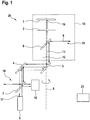
- FIG. 1 schematically shows an optical system 20 according to an embodiment of the invention.
- the optical system 20 comprises a rotation system 13, wherein the rotation system 13 is rotatable about a rotation axis 6. It is the aim of the optical system 20 to guide a signal beam 9 just about the rotation system 13, that no lateral offset and no Angular errors with respect to the axis of rotation 6 occur.
- the signal beam 9 must be precisely adjusted to the real, mechanical axis of rotation 6.
- the optical system has a plurality of mirrors whose function will be explained below.
- the signal beam 9 extends from a signal input 18 of the optical system 20 to a signal output 19 of the optical system 20.
- the signal beam 9 may be a different type of beam, in particular an imaging beam or a high-energy beam, in particular a laser beam.
- the signal input mirror 7 is partially transmissive, wherein a larger portion of the signal beam 9 is directed from the signal input mirror 7 to a rotational coupling mirror 4. At the same time, a smaller part of the signal beam 9 is passed through the signal coupling mirror 7 and impinges on an optical sensor 10.
- an autocollimator 5 wherein the autocollimator comprises an auxiliary light source and an angle sensor.
- the autocollimator as an auxiliary light source, an auxiliary beam 11 is emitted.
- the auxiliary beam 11 is in particular a laser beam.
- the auxiliary beam 11 is partially reflected by the signal input mirror 7, so that a part of the auxiliary beam 11 reaches the optical sensor 10.
- a further part of the auxiliary beam 11 passes through the signal coupling mirror 7 and extends to the rotational coupling mirror 4.
- the signal beam 9 and the auxiliary beam 11 can be compared via the optical sensor 10. In this way it is possible to synchronize the auxiliary beam 11 in angle and position with the signal beam 9. This means that in the case in which the auxiliary beam 11 is adjusted to the rotation axis 6, the signal beam 9 is also adjusted on the rotation axis 6. Thus, the adjustment of the signal beam 9 functions independently of the type of the signal beam. 9
- the rotary coupling mirror 4 is arranged tiltably.
- the further course of the signal beam 9 and of the auxiliary beam 11 can be influenced by the rotational coupling mirror 4.
- the signal beam 9 and the auxiliary beam 11 can be conducted to an axis coupling mirror 3.
- the axis coupling mirror 3 is in turn tiltably arranged so that a further course of the auxiliary beam 11 and the signal beam 9 can be influenced by the axis coupling mirror 3.
- signal beam 9 and auxiliary beam 11 can be conducted to a signal output mirror 8.
- the signal output mirror 8 reflects the signal beam 9, while the auxiliary beam 11 is passed through the signal output mirror 8.
- the signal beam 9 passes to the signal output 19 of the optical system 20.
- the auxiliary beam 11 reaches a reference mirror 2, wherein the reference mirror 2 reflects back a part of the auxiliary beam 11.
- the reflection auxiliary beam 12 which extends due to the back reflection on the same optical path as the auxiliary beam 11.
- the reflection auxiliary beam 12 reaches the autocollimator 5, in particular the angle sensor of the autocollimator 5.
- the reflection auxiliary beam projection 17, which will be described below with reference to FIG FIG. 2 is explained.
- the rotation system 13 comprises the signal output mirror 8, the reference mirror 2 and the position detector 1. All of these components are cut by the rotation axis 6. Also, all these components are arranged rotatably about the axis of rotation 6.
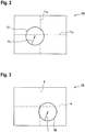
- a first measurement map 14 of the angle sensor of the autocollimator 5 is shown in FIG FIG. 2 shown.
- a first circular path is shown, the reflection auxiliary beam projection 17 on the angle sensor of the autocollimator 5 performs when the rotation system 13 is rotated.
- the first circular path has a first radius r ⁇ and first center coordinates ⁇ x, ⁇ y.
- the first radius ⁇ r of the first circular path is due to the fact that the reference mirror 2 is not aligned exactly perpendicular to the axis of rotation 6. Thus, by tilting the reference mirror 2, the first radius ⁇ r can be influenced.
- the first center point coordinates ⁇ x , ⁇ y of the center point of the circular path of the reflection auxiliary beam projection 17 can be influenced by the axis coupling mirror 3.
- the origin coordinates point to the point from which the auxiliary beam 11 was emitted. If the reference mirror 2 and the axis coupling mirror 3 are tilted until the first radius ⁇ r gives the value 0 and the first center point coordinates ⁇ x , ⁇ y lie in the origin of the first measuring field 14 in the first circular path, then the auxiliary beam 11 and thus Also, the signal beam 9 is aligned parallel to the axis of rotation 6.
- the first radius ⁇ r of the first circular path and can be influenced only by tilting the reference mirror 2, while the first center point coordinates ⁇ x , ⁇ y of the first circular path can be influenced only by tilting the Achseninkoppelador 3.
- these parameters are independently adjustable.
- the second measuring field 15 shows the course of the auxiliary beam projection 16 of the auxiliary beam 11 on the position detector 1 when the rotation system 13 is rotated. If the auxiliary beam 11 and thus the signal beam 9 are not located directly on the axis of rotation 6, the auxiliary beam projection 16 describes a second circular path about the axis of rotation 6.
- the second circular path has a second radius r and second center coordinates x, y.
- the auxiliary beam 11 and thus the signal beam 9 can be displaced parallel to the axis of rotation 6.
- the signal beam 9 is adjustable to the axis of rotation 6.
- the optical system 20 preferably also has a control device 21.
- the control device 21 is in particular a control device which continuously determines the angular deviation between the auxiliary beam 11 and reflection auxiliary beam 12 by means of the autocollimator 5 and the position of the auxiliary beam projection 16 by means of the position sensor 1 and adapts a tilting of the axis coupling mirror 3 and the rotational coupling mirror 4 and in particular of the reference mirror 2 to hold the auxiliary beam 11 and thus the signal beam 9 on the axis of rotation 6.
- axis coupling mirror 3 and rotational coupling mirror 4 takes place sequentially.
- the tilting of these mirrors can be combined so that an at least partial parallel adjustment of the auxiliary beam 11 and thus of the signal beam 9 takes place on the axis of rotation 6.
- the rotation system 13 can be rotated about the axis of rotation 6 to the in FIG. 2 to obtain the measurement shown.
- the first center point coordinates ⁇ x , ⁇ y it is possible to calculate a necessary tilting of the axis coupling mirror 3, in which the first circle center points to the origin of the in FIG. 2 shifts shown first measurement map 14.
- tilting of the axis coupling mirror 3 can be determined without the reference mirror 2 having to be exactly aligned beforehand, ie without the reference mirror 2 having to be perpendicular to the rotation axis 6, whereby the first radius ⁇ r would become 0.
- the joint adjustment of axis coupling mirror 3 and rotational coupling mirror 4 for displacement of the auxiliary beam 11 and the signal beam 9 parallel to the axis of rotation 6 is analogous as described above.
- a further special control possibility can be after a rotation of the rotation system 13, in which the in FIG. 2 and FIG. 3 imaged measurement images 14, 15 arise, the second radius r of the second circular path and the first center coordinates ⁇ x , ⁇ y determine the first circular path.
- a formula can be established which influence on the first center point coordinates ⁇ x , ⁇ y and / or on the second radius r has a tilting of either the axis coupling mirror 3 or the rotational coupling mirror 4.
- a system of equations with two equations and with two unknowns is thus present.
- FIG. 3 shows an alternative embodiment of the optical system 20. Elements with the same reference numerals as in FIG. 1 equivalent components as in FIG. 1 ,
- the optical system 20 comprises an azimuth rotation system 13 'and an elevation rotation system 13 "where an azimuth rotation axis 6' of the azimuth rotation system 13 'is perpendicular to an elevation rotation axis 6" of the elevation rotation system
- the optical system 20 advantageously comprises a Coudé beam path
- the signal beam 9 can thus be directed independently of one another in two spatial directions and can be stabilized with respect to both axes of rotation.
- the azimuth rotation system 13 ' has an azimuth signal output mirror 8' and an azimuth reference mirror 2 '.
- the azimuth rotation system 13 ' is constructed identically to the rotation system 13.
- the elevation rotation system 13 has an elevation signal output mirror 8" and an elevation reference mirror 2 ".
- the elevation rotation system 13 is also constructed the same as the rotation system 13.
- the signal beam 9 can be coupled into the azimuth rotation system 13 'via an azimuth axis coupling mirror 3', while the signal beam 9 can be coupled into the elevation rotation system 13 "via an elevation axis coupling mirror 3".
- the signal beam 9 from the azimuth signal output mirror 8 ' can be steered onto a deflection mirror 22, whereby the signal beam 9 can be steered by the deflection mirror 22 onto the elevation axis coupling mirror 3 "The elevation axis coupling-out mirror 8" directs the signal beam onto the signal exit 19 which is in FIG. 2 is shown as a further optical system.
- the optical system shown permits a stabilization of the signal beam 9 both with respect to the azimuth axis of rotation 6 'and the elevation axis of rotation 6 ", whereby the respective stabilization takes place analogously to the described stabilization by the rotation system 13.
- both an azimuth reference mirror 2 'and an elevation reference mirror 2 " are provided, with a position sensor (not shown) in each case being assigned to both the azimuth reference mirror 2' and the elevation reference mirror 2" ,
- a position sensor (not shown) in each case being assigned to both the azimuth reference mirror 2' and the elevation reference mirror 2" .
- stabilization in azimuth and elevation can be performed independently.
- preferably only a single reference mirror and a single position sensor are present.
- the stabilization of the signal beam 9 is to take place in real time with simultaneous rotation about both axes, deviations only arise at the individual axes of rotation by using only one reference mirror and only one position detector at the end of the rotation chain.
- the signal beam 9 is precisely stabilized to the output axis resulting from the current azimuth rotation angle and the instantaneous elevation rotation angle.
- the signal beam after the signal output mirror 8 "is stabilized in angle and position with respect to both axes of rotation either the coupling mirrors before the azimuth system, ie signal coupling mirror 7 and axis coupling mirror 3 'or the coupling mirror before the elevation system, ie deflection mirror 22 and elevation axis inclusion mirror 3" for the Stabilization can be used.
- each rotation system has its own reference mirror and its own position sensor, or alternatively, a single reference mirror 2 and single position sensor 1 is present. In the latter case, provision is made, in particular, for the reference mirror 2 and the position sensor 1 to be located behind the last rotation system through which the signal beam 9 passes before the signal beam leaves the optical system 20.
- corrections are advantageously made by tilting the respective coupling-in mirrors of the first two rotation systems, which the signal beam passes through when passing through the optical system.
- the corrections can be made by any Einkoppelspiegel the individual rotation systems. In this case, only the summation error is compensated at the end of the rotation systems, so that the signal beam 9 is stabilized only after leaving the optical system 20, but not with respect to the individual axes of the Rotatiossysteme.
- the invention thus describes a simple and rapid method and a device with which an optical beam path can be easily and quickly adjusted to a mechanical axis of rotation and / or stabilized.
- a particular advantage of the invention is that no external references are necessary, so that none of the elements used must be pre-positioned with high precision. Also, the real mechanical axis of rotation need not be known exactly.
- a further advantage consists in the possibility that this adjustment can be carried out in a controlled manner in order to stabilize it, with which, in particular, mechanical inaccuracies can be effectively compensated.
Landscapes
- Physics & Mathematics (AREA)
- General Physics & Mathematics (AREA)
- Optics & Photonics (AREA)
- Engineering & Computer Science (AREA)
- Radar, Positioning & Navigation (AREA)
- Remote Sensing (AREA)
- Mounting And Adjusting Of Optical Elements (AREA)
- Length Measuring Devices By Optical Means (AREA)
Abstract
Description
- Die Erfindung betrifft ein optisches System. Weiterhin betrifft die Erfindung ein Verfahren zum Justieren eines optischen Strahls, insbesondere eines Signalstrahls, wobei bevorzugt ein derartiges optisches System verwendet wird. Mit dem erfindungsgemäßen optischen System und dem erfindungsgemäßen Verfahren ist insbesondere ein Signalstrahl räumlich, insbesondere in Winkel und Position, stabilisierbar.
- Wird ein optischer Strahl über eine rotierbare Anordnung geführt, so erfährt der Strahl eine Rotation um die momentane reale mechanische Rotationsachse. Eine solche rotierbare Anordnung kann insbesondere ein Coudé-Strahlengang sein. Der optische Strahl kann insbesondere ein Laserstrahl oder ein abbildender Strahl sein.
- Um eine Abbildung in einem derartigen rotierenden System zu stabilisieren oder um einen rotationssymmetrischen Strahl ortsfest zu stabilisieren, muss der Strahl exakt auf die reale mechanische Rotationsachse justiert werden. Außerdem darf der Strahl besagte Rotationsachse auch während der Rotation nicht verlassen. In vorhandenen optischen Systemen können diese Voraussetzungen nicht oder nur bedingt eingehalten werden.
- Es ist daher Aufgabe der vorliegenden Erfindung ein optisches System bereitzustellen, das bei einfacher und kostengünstiger Herstellung und Montage eine sichere und zuverlässige Stabilisierung eines Signalstrahls auf der Rotationsachse eines rotierbaren Systems ermöglicht. Es ist außerdem Aufgabe der Erfindung, ein entsprechendes Verfahren anzugeben.
- Gelöst wird die Aufgabe durch die Merkmale der nebengeordneten Ansprüche. Somit wird die Aufgabe gelöst durch ein optisches System, das einen Signaleingang, einen Signalausgang, eine Hilfslichtquelle und ein Rotationssystem umfasst. An dem Signaleingang ist ein Signalstrahl aufnehmbar. An dem Signalausgang ist der Signalstrahl ausgebbar. Bei dem Signalstrahl kann es sich um einen abbildenden Strahl handeln. Alternativ oder zusätzlich kann der Signalstrahl ein hochenergetischer Strahl, wie insbesondere ein Laserstrahl, sein. Mit der Hilfslichtquelle ist ein Hilfslichtstrahl aussendbar. Dabei ist vorgesehen, dass der Hilfslichtstrahl in Winkel und Position zu dem Signalstrahl synchron ist. Alternativ kann der Hilfslichtstrahl aus dem Signalstrahl ausgekoppelt werden. Das Rotationssystem ist um eine Rotationsachse rotierbar und weist einen Signalauskoppelspiegel und einen Referenzspiegel auf. Außerdem weist das optische System einen Achseinkoppelspiegel auf. Mit dem Achseinkoppelspiegel sind der Signalstrahl und der Hilfsstrahl in das Rotationssystem einkoppelbar. Mit dem Signalauskoppelspiegel wiederum ist der Signalstrahl aus dem Rotationssystem auskoppelbar. Besonders vorteilhaft ist vorgesehen, dass der Signalstrahl von dem Signalauskoppelspiegel unmittelbar zu dem Signalausgang leitbar ist. Dazu erfolgt vorteilhafter Weise keine Beeinflussung des Signalstrahls.
- Bevorzugt ist vorgesehen, dass die Rotationsachse den Achseinkoppelspiegel, den Signalauskoppelspiegel und den Referenzspiegel schneidet. Weiterhin ist vorgesehen, dass der Signalstrahl von dem Signaleingang über den Achseinkoppelspiegel zu dem Signalauskoppelspiegel lenkbar ist. Der Hilfsstrahl wiederum ist über den Achseinkoppelspiegel und durch den Achsauskoppelspiegel hindurch auf den Referenzspiegel lenkbar. Von dem Referenzspiegel ist der Hilfsstrahl zumindest teilweise zu einem Reflexionshilfsstrahl rückreflektierbar. Somit verläuft der Reflexionshilfsstrahl insbesondere durch den Achsauskoppelspiegel hindurch und über den Achseinkoppelspiegel zurück zu der Hilfslichtquelle. Weiterhin ist vorgesehen, dass das optische System einen Winkelsensor umfasst. Mit dem Winkelsensor ist eine Winkelabweichung zwischen dem Hilfsstrahl und dem Reflexionshilfsstrahl erfassbar. Es ist ersichtlich, dass bei Nichtrotieren des Rotationssystems eine derartige Winkelabweichung nur dann vorhanden ist, wenn der Referenzspiegel inkorrekt eingestellt ist. Somit kann durch Verkippen des Referenzspiegels die Winkelabweichung beeinflusst werden. Sollte bei rotierendem Rotationssystem eine Winkelabweichung vorhanden sein, so sind der Signalstrahl und der Hilfsstrahl nicht auf die Rotationsachse ausgerichtet. Somit ist durch Verkippen das Achseinkoppelspiegels die Winkelabweichung beeinflussbar. Das optische System ermöglicht daher durch Verkippen des Achseinkoppelspiegels den Signalstrahl unter Bestimmung der Winkelabweichung parallel zu der Rotationsachse auszurichten, wobei insbesondere ein zusätzliches Verkippen des Referenzspiegels zum Ausrichten des Reflexionshilfsstrahls erfolgt.
- Besonders vorteilhaft eignet sich das optische System für verschiedene Arten von Signalstrahlen. So kann der Signalstrahl ein abbildender Strahl oder ein Laserstrahl sein. Durch das synchrone Einkoppeln des Hilfsstrahls, bedingt eine Ausrichtung des Hilfsstrahls parallel zu der Rotationsachse, dass auch der Signalstrahl zwingend parallel zu der Rotationsachse ausgerichtet ist. Der Hilfsstrahl lässt sich über den Referenzspiegel leicht reflektieren, sodass eine Messung von Winkelabweichungen ermöglicht ist. Die Winkelabweichungen gelten daher sowohl für den Hilfsstrahl als auch für den Signalstrahl.
- Die Unteransprüche haben bevorzugte Weiterbildungen der Erfindung zum Inhalt.
- Vorteilhafter Weise ist der Winkelsensor und die Hilfslichtquelle in einer einzigen Vorrichtung zusammengefasst. Bei dieser einzigen Vorrichtung handelt es sich vorteilhafter Weise um einen Autokollimator. Somit ist feststellbar, unter welchem Winkel der Reflexionshilfsstrahl auf dem Autokollimator auftrifft. Dies ist vergleichbar mit dem Hilfsstrahl, sodass eine Winkelabweichung zwischen Reflexionshilfsstrahl und Hilfsstrahl erfassbar ist. Da die Hilfslichtquelle und der Winkelsensor in dem Autokollimator zusammengefasst sind, und da der Reflexionshilfsstrahl aufgrund der Rückreflexion durch den Referenzspiegel denselben optischen Weg wie der Hilfsstrahl zurücklegt, sind keine zusätzlichen optischen Systeme notwendig, um den Reflexionshilfsstrahl umzulenken. Die Bestimmung der Winkelabweichung durch den Autokollimator erfolgt daher auf sehr einfache und dennoch zuverlässige Art und Weise.
- In einer bevorzugten Ausführungsform beschreibt eine Reflexionshilfsstrahlprojektion des Reflexionshilfsstrahls auf dem Winkelsensor eine erste Kreisbahn, wenn das Rotationssystem rotiert. Dabei ist durch Verkippen des Reflexionsspiegels ein erster Radius der ersten Kreisbahn beeinflussbar. Durch Verkippen des Achseinkoppelspiegels sind erste Mittelpunktkoordinaten der ersten Kreisbahn beeinflussbar. Es ist somit ersichtlich, dass die Winkelabweichung durch Verkippen des Achseinkoppelspiegels und des Reflexionsspiegels beeinflussbar sind. Insbesondere sind die Beeinflussungen der Winkelabweichung durch Reflexionsspiegel und Achseinkoppelspiegel unabhängig voneinander. So kann der Hilfsstrahl und damit der Signalstrahl durch Verkippen des Achseinkoppelspiegels parallel zu der Rotationsachse des Rotationssystems ausgerichtet werden, wobei insbesondere ein Verkippen des Referenzspiegels zum Ausrichten des Reflexionshilfsstrahls erfolgt.
- Das optische System weist bevorzugt einen Signaleinkoppelspiegel auf. Dazu ist vorgesehen, dass der Signalstrahl von dem Signaleingang teilweise über den Signaleinkoppelspiegel zu dem Achseinkoppelspiegel und teilweise über den Signaleinkoppelspiegel zu einem optischen Sensor leitbar ist. Besonders vorteilhaft ist derjenige Anteil des Signalstrahls, der zu dem Achseinkoppelspiegel leitbar ist, größer als derjenige Anteil des Signalstrahls, der zu dem optischen Sensor leitbar ist. Durch den Signaleinkoppelspiegel ist außerdem der Hilfsstrahl von der Hilfslichtquelle teilweise zu dem Achseinkoppelspiegel und teilweise zu dem optischen Sensor leitbar. Somit ist von dem optischen Sensor sowohl der Signalstrahl als auch der Hilfsstrahl erfassbar. Anhand von Messdaten des optischen Sensors sind somit der Signalstrahl und der Hilfsstrahl in Winkel und Position synchronisierbar. Dies führt vorteilhafter Weise dazu, dass jede Beeinflussung des Hilfsstrahls gleichbedeutend ist mit einer Beeinflussung des Signalstrahls. Da eine Winkelabweichung des Hilfsstrahls gegenüber dem Reflexionshilfsstrahl durch den Winkelsensor, insbesondere durch den Autokollimator, sehr einfach bestimmbar ist, lässt sich somit auch die Winkelabweichung des Signalstrahls auf sehr einfache Art und Weise bestimmen. Somit ist die Ausrichtung des Signalstrahls parallel zu der Rotationsachse sehr einfach möglich.
- In einer weiteren bevorzugten Ausführungsform der Erfindung weist das optische System einen Rotationseinkoppelspiegel auf. Der Signalstrahl und der Hilfsstrahl sind über den Rotationseinkoppelspiegel in vorteilhafter Weise in das Rotationssystem einkoppelbar. Insbesondere sind der Hilfsstrahl und der Signalstrahl über den Rotationseinkoppelspiegel auf den Achseinkoppelspiegel lenkbar. Der Rotationseinkoppelspiegel ist vorteilhafter Weise verkippbar, um eine Position des Signalstrahls und des Hilfsstrahls einzustellen.
- In einer besonders vorteilhaften Ausführungsform weist das Rotationssystem einen Positionsdetektor auf. Mit dem Positionsdetektor ist eine Hilfsstrahlprojektion des Hilfsstrahls detektierbar. Besonders vorteilhaft ist der Positionsdetektor derart angeordnet, dass die Rotationsachse des Rotationssystems den Positionsdetektor schneidet. Der Hilfsstrahl ist durch den Referenzspiegel vorteilhafter Weise teilweise zu dem Reflexionshilfsstrahl rückreflektierbar und teilweise durch den Referenzspiegel hindurch zur Abbildung der Hilfsstrahlprojektion auf den Positionsdetektor leitbar. Durch eine derartige Anordnung beschreibt die Hilfsstrahlprojektion eine zweite Kreisbahn auf dem Positionsdetektor, wenn der Hilfsstrahl parallel zu der Rotationsachse ausgerichtet ist und die Rotationsvorrichtung rotiert. Die Kreisbahn erstreckt sich dabei um einen Mittelpunkt, wobei der Mittelpunkt demjenigen Punkt entspricht, an dem die Rotationsachse den Positionsdetektor schneidet. Es ist vorgesehen, dass durch Verkippen des Rotationseinkoppelspiegels der zweite Radius der zweiten Kreisbahn beeinflussbar ist.
- Außerdem ist besonders vorteilhaft vorgesehen, dass durch gemeinsames Verkippen des Rotationseinkoppelspiegels und des Achseinkoppelspiegels der Hilfsstrahl und damit auch der Signalstrahl parallel zu der Rotationsachse verschiebbar ist.
- Die Hilfslichtquelle ist bevorzugt eine Laserlichtquelle. Somit ist besonders vorteilhaft vorgesehen, dass ein Autokollimator vorhanden ist, der einerseits ein Laserlicht aussendet, andererseits zur Detektion einer Rückreflexion dieses Laserlichts ausgebildet ist. Dabei ist das Laserlicht einfach und zuverlässig handhabbar, sodass sichere und zuverlässige Messungen erfolgen.
- Vorteilhafterweise weist das optische System eine Steuerungsvorrichtung auf. Die Steuerungsvorrichtung ist dabei eingerichtet, den Referenzspiegel zu verkippen, bis der erste Radius der ersten Kreisbahn der Reflexionshilfsstrahlprojektion auf dem Winkelsensor den Wert 0 ergibt. Auf diese Weise ist der Referenzspiegel derart ausgerichtet, dass die Rotationsachse den Referenzspiegel unter einem Winkel von 90° schneidet. Weiterhin ist die Steuervorrichtung ausgebildet, den Achseinkoppelspiegel zu verkippen, bis die ersten Mittelpunktskoordinaten der ersten Kreisbahn der Reflexionshilfsstrahlprojektion auf dem Winkelsensor denjenigen Winkelkoordinaten entsprechen, aus denen der Hilfsstrahl ausgesandt worden ist. Insbesondere entsprechen diejenigen Winkelkoordinaten, aus denen der Hilfsstrahl ausgesandt worden ist, den Ursprungskoordinaten eines Koordinatensystems, in dem die erste Kreisbahn bestimmbar ist. Auf diese Weise ist keine Winkelabweichung zwischen dem Hilfsstrahl und dem Reflexionshilfsstrahl vorhanden. Dies bedeutet, dass der Hilfsstrahl und damit auch der Reflexionshilfsstrahl sowie der Signalstrahl parallel zu der Rotationsachse ausgerichtet sind. Zusätzlich ist die Steuerungsvorrichtung eingerichtet, den Rotationseinkoppelspiegel und den Achseinkoppelspiegel kombiniert zu verkippen, bis der zweite Radius der zweiten Kreisbahn den Wert 0 ergibt. In diesem Fall sind der Hilfsstrahl und damit auch der Reflexionshilfsstrahl sowie der Signalstrahl auf die Rotationsachse verschoben. Somit ist der Signalstrahl auf der Rotationsachse stabilisiert, sodass eine Rotation des Rotationssystems, mit Ausnahme einer Drehung um sich selbst, nicht zu einer Beeinflussung des Signalstrahls führt.
- Alternativ oder zusätzlich ist vorgesehen, dass die Steuerungsvorrichtung eingerichtet ist, das Rotationssystem zum Rotieren um die Rotationsachse anzusteuern. Weiterhin ist die Steuerungsvorrichtung eingerichtet, die ersten Mittelpunktskoordinaten der ersten Kreisbahn zu bestimmen. Aus den ersten Mittelpunktskoordinaten der ersten Kreisbahn der Reflexionshilfsstrahlprojektion lässt sich eine notwendige Verkippung für den Achseinkoppelspiegel bestimmen. Die notwendige Verkippung des Achseinkoppelspiegels führt dazu, dass die Mittelpunktskoordinaten der ersten Kreisbahn auf diejenigen Koordinaten verschoben werden, von denen aus der Hilfsstrahl ausgesandt worden ist. Somit ist eine Verkippung des Reflexionsspiegels nicht notwendig. Die Steuerungsvorrichtung ist weiterhin eingerichtet, den Achseinkoppelspiegel um die notwendige Verkippung zu verkippen. Schließlich ist die Steuerungsvorrichtung eingerichtet, den Rotationseinkoppelspiegel und den Achseinkoppelspiegel kombiniert zu verkippen, bis der zweite Radius der zweiten Kreisbahn den Wert 0 ergibt.
- Das optische System ist alternativ oder zusätzlich derart mit einer Steuerungsvorrichtung ausgebildet, wobei die Steuerungsvorrichtung zum Ansteuern des Rotationssystems zum Rotieren um die Rotationsachse ausgebildet ist. Weiterhin ist die Steuerungsvorrichtung ausgebildet, die ersten Mittelpunktskoordinaten der ersten Kreisbahn sowie den zweiten Radius der zweiten Kreisbahn zu bestimmen. Außerdem ist die Steuerungsvorrichtung ausgebildet, eine notwendige Verkippung für den Achseinkoppelspiegel und den Rotationseinkoppelspiegel zu bestimmen, damit die ersten Mittelpunktskoordinaten der Kreisbahn der Reflexionshilfsstrahlprojektion auf dem Winkelsensor denjenigen Koordinaten entsprechen, von denen aus der Hilfsstrahl ausgesandt worden ist und der zweite Radius zu 0 wird. Es ist ersichtlich, dass sich eine erste Formel aufstellen lässt, in der die Auswirkung einer Verkippung des Achseinkoppelspiegels auf die ersten Mittelpunktskoordinaten dargestellt ist. Weiterhin lässt sich eine zweite Formel aufstellen, in der die Auswirkung einer Verkippung des Rotationseinkoppelspiegels auf die Mittelpunktskoordinaten sowie auf die ersten Mittelpunktskoordinaten sowie auf den zweiten Radius darstellbar ist. Zusammen mit dem zweiten Radius sowie den ersten Mittelpunktskoordinaten ist somit ein mathematisches Gleichungssystem mit zwei Gleichungen und zwei Unbekannten vorhanden. Somit existiert genau eine Lösung, nämlich die genannten notwendigen Verkippungen von Achseinkoppelspiegel und Rotationseinkoppelspiegel. Die Steuerungsvorrichtung ist schließlich eingerichtet, den Achseinkoppelspiegel und den Rotationseinkoppelspiegel um die zuvor bestimmten notwendigen Verkippungen zu verkippen. Auf diese Weise erfolgt die Verkippung der einzelnen Spiegel nicht sequenziell, sondern parallel, wodurch ein schnelles und sicheres Ausrichten des Hilfsstrahls und damit auch des Signalstrahls auf die Rotationsachse des Rotationssystems ermöglicht ist.
- Besonders vorteilhaft ist die Steuerungsvorrichtung eine Regelvorrichtung, um den Hilfsstrahl auf der Rotationsachse zu halten. Somit ist insbesondere vorgesehen, dass fortlaufend zumindest die ersten Mittelpunktskoordinaten und der zweite Radius bestimmt wird, wobei die Steuerungsvorrichtung eingerichtet ist, eine Verkippung von Achseinkoppelspiegel und Rotationseinkoppelspiegel, sowie insbesondere des Referenzspiegels, fortwährend einer Veränderung der ersten Mittelpunktskoordinaten und/oder des zweiten Radius anzupassen.
- Das optische System zeichnet sich vorteilhafterweise dadurch aus, dass das Rotationssystem ein Azimut-Rotationssystem und ein Elevations-Rotationssystem umfasst. Dabei ist das Azimut-Rotationssystem um eine Azimut-Rotationsachse rotierbar, während das Elevations-Rotationssystem um eine, insbesondere zur Azimut-Rotationsachse senkrechten, Elevations-Rotationsachse rotierbar ist. Bevorzugt ist das Azimut-Rotationssystem Teil des Elevations-Rotationssystems, so dass das Azimut-Rotationssystem als Ganzes um die Elevations-Rotationsachse rotierbar ist. Alternativ ist das Elevations-Rotationssystem bevorzugt Teil des Azimut-Rotationssystems, so dass das Elevations-Rotationssystem als Ganzes um die Azimut-Rotationsachse rotierbar ist. Der Achseinkoppelspiegel umfasst einen Azimut-Achseinkoppelspiegel zum Einkoppeln des Signalstrahls und des Hilfsstrahls in das Azimut-Rotationssystem und einen Elevations-Achseinkoppelspiegel zum Einkoppeln des Signalstrahls und des Hilfsstrahls in das Elevations-Rotationssystem. Außerdem ist vorgesehen, dass das Azimut-Rotationssystem einen Azimut-Signalauskoppelspiegel zum Auskoppeln des Signalstrahls aus dem Azimut-Rotationssystem, und insbesondere einen Azimut-Referenzspiegel, umfasst wobei die Azimut-Rotationsachse den Azimut-Achseinkoppelspiegel, den Azimut-Signalauskoppelspiegel und den Azimut-Referenzspiegel vorteilhafterweise schneidet. Ebenso ist vorgesehen, dass das Elevations-Rotationssystem einen Elevations-Signalauskoppelspiegel zum Auskoppeln des Signalstrahls aus dem Elevations-Rotationssystem und insbesondere einen Elevations-Referenzspiegel aufweist, wobei die Elevations-Rotationsachse den Elevations-Achseinkoppelspiegel, den Elevations-Signalauskoppelspiegel und den Elevations-Referenzspiegel vorteilhafterweise schneidet. Somit lässt sich der Signalstrahl vorteilhafterweise auf zwei senkrecht zueinander stehende Achse, die Azimut-Rotationsachse und die Elevations-Rotationsachse, stabilisieren.
- Die Erfindung betrifft außerdem ein Verfahren zum Justieren eines Signalstrahls. Insbesondere wird das Verfahren mit dem optischen System wie zuvor beschrieben ausgeführt. Das erfindungsgemäße Verfahren umfasst die folgenden Schritte: zunächst erfolgt ein Verkippen des Referenzspiegels, bis der erste Radius der ersten Kreisbahn der Reflexionshilfsstrahlprojektion auf die Winkelsensoren den Wert 0 ergibt. Auf diese Weise wird der Referenzspiegel derart ausgerichtet, dass die Rotationsachse des Rotationssystems zu dem Referenzspiegel einen Winkel von 90° einnimmt.
- Anschließend erfolgt eine Verkippung des Achseinkoppelspiegels, bis die ersten Mittelpunktskoordinaten der Kreisbahn der Reflexionshilfsstrahlprojektion auf dem Winkelsensor denjenigen Koordinaten entsprechen, von denen aus der Hilfsstrahl ausgesandt worden ist. Somit ist eine Winkelabweichung zwischen Hilfsstrahl und Reflexionshilfsstrahl nicht mehr vorhanden, wodurch der Hilfsstrahl und damit auch der Reflexionshilfsstrahl sowie der Signalstrahl parallel zu der Rotationsachse des Rotationssystems ausgerichtet sind. Danach werden der Rotationseinkoppelspiegel und der Achseinkoppelspiegel kombiniert verkippt, bis der zweite Radius der zweiten Kreisbahn den Wert 0 ergibt. Somit erfolgt eine Verschiebung des Hilfsstrahls und damit auch des Signalstrahls auf die Rotationsachse. Eine Rotation des Rotationssystems führt damit bis auf eine Rotation um sich selbst nicht mehr zu einer Veränderung des Signalstrahls. Somit ist der Signalstrahl auf der Rotationsachse stabilisiert.
- Alternativ oder zusätzlich umfasst das Verfahren die erfolgenden Schritte: Zunächst erfolgt ein Rotieren des Rotationssystem um die Rotationsachse. Anschließend erfolgt ein Bestimmen der ersten Mittelpunktskoordinaten der ersten Kreisbahn. Danach wird die notwendige Verkippung für den Achseinkoppelspiegel bestimmt, um die ersten Mittelpunktskoordinaten der ersten Kreisbahn der Reflexionshilfsstrahlprojektion auf dem Winkelsensor auf diejenigen Koordinaten abzubilden, von denen aus der Hilfsstrahl ausgesandt worden ist. Somit erfolgt ein Ausrichten des Hilfsstrahls parallel zu der Rotationsachse des Rotationssystems, wobei eine Ausrichtung des Referenzspiegels nicht notwendig ist. Anschließend wird der Achseinkoppelspiegel um die zuvor bestimmte notwendige Verkippung verkippt. Schließlich erfolgt ein kombiniertes Verkippen des Rotationseinkoppelspiegels sowie des Achseinkoppelspiegels, bis der Radius der zweiten Kreisbahn den Wert 0 ergibt.
- Schließlich ist bevorzugt vorgesehen, dass das Verfahren die folgenden Schritte umfasst: Wiederum erfolgt zunächst ein Rotieren des Rotationssystem um die Rotationsachse. Anschließend werden die ersten Mittelpunktkoordinaten der ersten Kreisbahn sowie der zweite Radius der zweiten Kreisbahn bestimmt. Aus diesen Parametern lässt sich eine notwendige Verkippung für den Achseinkoppelspiegel und für den Rotationseinkoppelspiegel bestimmen. Bei der notwendigen Verkippung erfolgt ein Verschieben der ersten Mittelpunktskoordinaten der Kreisbahn der Reflexionshilfsstrahlprojektion auf den Winkelsensor auf diejenigen Winkelkoordinaten, aus denen der Hilfsstrahl ausgesandt worden ist. Weiterhin wird der zweite Radius zu 0 gesetzt. Die notwendige Verkippung von Achseinkoppelspiegel und Rotationseinkoppelspiegel, um die genannten Auswirkungen auf die ersten Mittelpunktskoordinaten und auf den zweiten Radius zu erreichen, ist insbesondere wie zuvor beschrieben berechenbar. Als letzter Schritt erfolgt ein Verkippen des Achseinkoppelspiegels und des Rotationseinkoppelspiegels um die bestimmte notwendige Verkippung.
- Die Erfindung wird nun anhand eines Ausführungsbeispiels unter Berücksichtigung der beigefügten Zeichnungen im Detail beschrieben. In den Zeichnungen ist:
- Fig. 1
- eine schematische Abbildung des optischen Systems gemäß einem Ausführungsbeispiel der Erfindung,
- Fig. 2
- eine schematische Abbildung einer Messung des Winkelsensors des optischen Systems gemäß dem Ausführungsbeispiel der Erfindung,
- Fig. 3
- eine schematische Abbildung der Messung des Positionsdetektors des optischen Systems gemäß dem Ausführungsbeispiel der Erfindung, und
- Fig. 4
- eine schematische Abbildung des optischen Systems gemäß einem alternativen Ausführungsbeispiel der Erfindung.
-
Figur 1 zeigt schematisch ein optisches System 20 gemäß einem Ausführungsbeispiel der Erfindung. Das optische System 20 umfasst ein Rotationssystem 13, wobei das Rotationssystem 13 um eine Rotationsachse 6 rotierbar ist. Es ist Ziel des optischen Systems 20 einen Signalstrahl 9 gerade so über das Rotationssystem 13 zu führen, dass kein lateraler Versatz und kein Winkelfehler bezüglich der Rotationsachse 6 auftreten. Zu diesem Zweck muss der Signalstrahl 9 genau auf der realen, mechanischen Rotationsachse 6 justiert sein. Zum Justieren des Signalstrahls 9 auf die Rotationsachse 6 weist das optische System eine Vielzahl von Spiegeln auf, deren Funktion nachfolgend erklärt wird. - Außerdem ist vorgesehen, dass sich der Signalstrahl 9 von einem Signaleingang 18 des optischen Systems 20 zu einem Signalausgang 19 des optischen Systems 20 erstreckt. Der Signalstrahl 9 kann eine unterschiedliche Art von Strahl sein, insbesondere ein abbildender Strahl oder ein hochenergetischer Strahl, insbesondere ein Laserstrahl.
- Von dem Signaleingang 18 gelangt der Signalstrahl 9 auf einen Signaleinkoppelspiegel 7. Der Signaleinkoppelspiegel 7 ist teildurchlässig, wobei ein größerer Anteil des Signalsstrahls 9 von dem Signaleinkoppelspiegel 7 auf einen Rotationseinkoppelspiegel 4 gelenkt wird. Gleichzeitig wird ein geringerer Teil des Signalstrahls 9 durch den Signaleinkoppelspiegel 7 hindurchgeleitet und trifft auf einen optischen Sensor 10.
- Weiterhin ist ein Autokollimator 5 vorhanden, wobei der Autokollimator eine Hilfslichtquelle und einen Winkelsensor umfasst. Mit dem Autokollimator als Hilfslichtquelle ist ein Hilfsstrahl 11 aussendbar. Der Hilfsstrahl 11 ist insbesondere ein Laserstrahl. Wiederum ist der Hilfsstrahl 11 teilweise von dem Signaleinkoppelspiegel 7 reflektierbar, sodass ein Teil des Hilfsstrahls 11 auf den optischen Sensor 10 gelangt. Ein weiterer Teil des Hilfsstrahls 11 gelangt durch den Signaleinkoppelspiegel 7 hindurch und verläuft zu dem Rotationseinkoppelspiegel 4.
- Über den optischen Sensor 10 lassen sich der Signalstrahl 9 und der Hilfsstrahl 11 vergleichen. Auf diese Weise ist ermöglicht, den Hilfsstrahl 11 in Winkel und Position mit dem Signalstrahl 9 zu synchronisieren. Dies bedeutet, dass in dem Fall, in dem der Hilfsstrahl 11 auf die Rotationsachse 6 justiert wird, der Signalstrahl 9 ebenfalls auf der Rotationsachse 6 justiert ist. Somit funktioniert das Justieren des Signalstrahls 9 unabhängig von der Art des Signalstrahls 9.
- Der Rotationseinkoppelspiegel 4 ist verkippbar angeordnet. Somit lässt sich der weitere Verlauf des Signalstrahls 9 und des Hilfsstrahls 11 durch den Rotationseinkoppelspiegel 4 beeinflussen. Von dem Rotationseinkoppelspiegel 4 ist der Signalstrahl 9 und der Hilfsstrahl 11 auf einen Achseinkoppelspiegel 3 leitbar. Der Achseinkoppelspiegel 3 ist wiederum verkippbar angeordnet, sodass ein weiterer Verlauf des Hilfsstrahls 11 und des Signalstrahls 9 von dem Achseinkoppelspiegel 3 beeinflussbar ist.
- Von dem Achseinkoppelspiegel 3 sind Signalstrahl 9 und Hilfsstrahl 11 auf einen Signalauskoppelspiegel 8 leitbar. Der Signalauskoppelspiegel 8 reflektiert den Signalstrahl 9, während der Hilfsstrahl 11 durch den Signalauskoppelspiegel 8 hindurchgeleitet wird. Von dem Signalauskoppelspiegel 8 gelangt der Signalstrahl 9 zu dem Signalausgang 19 des optischen Systems 20. Der Hilfsstrahl 11 gelangt zu einem Referenzspiegel 2, wobei der Referenzspiegel 2 einen Teil des Hilfsstrahls 11 rückreflektiert. Auf diese Weise entsteht der Reflektionshilfsstrahl 12, der aufgrund der Rückreflektion über den gleichen optischen Weg wie der Hilfsstrahl 11 verläuft. Somit gelangt der Reflexionshilfsstrahl 12 auf den Autokollimator 5, insbesondere auf den Winkelsensor des Autokollimators 5. Auf dem Winkelsensor entsteht daher die Reflexionshilfsstrahlprojektion 17, die nachfolgend mit Bezug auf
Figur 2 erklärt wird. - Der Teil des Hilfsstrahls 11, der von dem Referenzspiegel 2 nicht rückreflektiert wird, gelangt durch den Referenzspiegel 2 auf einen Positionsdetektor 1. Auf dem Positionsdetektor 1 entsteht somit eine Hilfsstrahlprojektion 16 des Hilfsstrahls 11.
- Das Rotationssystem 13 umfasst den Signalauskoppelspiegel 8, den Referenzspiegel 2 und den Positionsdetektor 1. Alle diese Komponenten werden von der Rotationsachse 6 geschnitten. Auch sind alle diese Komponenten rotierbar um die Rotationsachse 6 angeordnet.
- Anhand des Winkelsensors des Autokollimators 5 lässt sich eine Winkelabweichung zwischen dem Hilfsstrahl 11 und dem Reflexionshilfsstrahl 12 bestimmen. Eine erste Messabbildung 14 des Winkelsensors des Autokollimators 5 ist in
Figur 2 dargestellt. In der ersten Messabbildung 14 ist eine erste Kreisbahn dargestellt, die Reflexionshilfsstrahlprojektion 17 auf dem Winkelsensor des Autokollimators 5 ausführt, wenn das Rotationssystem 13 rotiert wird. Die erste Kreisbahn weist einen ersten Radius αr sowie erste Mittelpunktskoordinaten αx, αy auf. Der erste Radius αr der ersten Kreisbahn kommt dadurch zustanden, dass der Referenzspiegel 2 nicht exakt senkrecht zu der Rotationsachse 6 ausgerichtet ist. Somit kann durch eine Verkippung des Referenzspiegels 2 der erste Radius αr beeinflusst werden. Die erste Mittelpunktskoordinaten αx, αy des Mittelpunkts der Kreisbahn der Reflexionshilfsstrahlprojektion 17 lassen sich durch den Achseinkoppelspiegel 3 beeinflussen. In dem inFigur 2 gezeigten ersten Messfeld 14 deuten die Ursprungskoordinaten auf denjenigen Punkt hin, von dem der Hilfsstrahl 11 ausgesandt wurde. Werden der Referenzspiegel 2 und der Achseinkoppelspiegel 3 solange verkippt, bis der erste Radius αr den Wert 0 ergibt und die ersten Mittelpunktskoordinaten αx, αy bei der ersten Kreisbahn in den Ursprung des ersten Messfelds 14 liegen, so ist der Hilfsstrahl 11 und damit auch der Signalstrahl 9 parallel zu der Rotationsachse 6 ausgerichtet. Dabei ist vorteilhaft, dass der erste Radius αr der ersten Kreisbahn und nur durch eine Verkippung des Referenzspiegels 2 beeinflussbar ist, während die ersten Mittelpunktskoordinaten αx, αy der ersten Kreisbahn nur durch Verkippung des Achseinkoppelspiegels 3 beeinflussbar sind. Somit sind diese Parameter unabhängig voneinander einstellbar. - Wurde der Signalstrahl 9 und der Hilfsstrahl 11 wie zuvor beschrieben eingestellt, so ergibt sich eine Messung wie in dem zweiten Messfeld 15 in
Figur 3 dargestellt ist. Das zweite Messfeld 15 zeigt den Verlauf der Hilfsstrahlprojektion 16 des Hilfsstrahls 11 auf den Positionsdetektor 1, wenn das Rotationssystem 13 rotiert wird. Befindet sich der Hilfsstrahl 11 und damit der Signalstrahl 9 nicht unmittelbar auf der Rotationsachse 6, so beschreibt die Hilfsstrahlprojektion 16 eine zweite Kreisbahn, um die Rotationsachse 6. Die zweite Kreisbahn weist einen zweiten Radius r sowie zweite Mittelpunktskoordinaten x, y auf. Über gemeinsames Verkippen des Rotationseinkoppelspiegels 4 und des Achseinkoppelspiegels 3 ist der zweite Radius r der zweiten Kreisbahn beeinflussbar. Somit lässt sich durch gemeinsames Verkippen von Achseinkoppelspiegel 3 und Rotationseinkoppelspiegel 4 der Hilfsstrahl 11 und damit der Signalstrahl 9 parallel zu der Rotationsachse 6 verschieben. Auf diese Weise ist der Signalstrahl 9 auf die Rotationsachse 6 justierbar. - Das optische System 20 weist bevorzugt außerdem eine Steuerungsvorrichtung 21 auf. Die Steuerungsvorrichtung 21 ist insbesondere eine Regelvorrichtung, die fortlaufend die Winkelabweichung zwischen Hilfsstrahl 11 und Reflexionshilfsstrahl 12 mittels des Autokollimators 5 sowie die Position der Hilfsstrahlprojektion 16 mittels des Positionssensors 1 bestimmt und eine Verkippung von Achseinkoppelspiegel 3 und Rotationseinkoppelspiegel 4, sowie insbesondere des Referenzspiegels 2, anpasst, um den Hilfsstrahl 11 und damit den Signalstrahl 9 auf der Rotationsachse 6 zu halten.
- Zuvor wurde beschrieben, wie die Verkippung von Referenzspiegel 2, Achseinkoppelspiegel 3 und Rotationseinkoppelspiegel 4 sequenziell erfolgt. Vorteilhafterweise können die Verkippungen dieser Spiegel zusammengefasst werden, sodass ein zumindest teilweises paralleles Justieren des Hilfsstrahls 11 und damit des Signalstrahls 9 auf der Rotationsachse 6 erfolgt.
- So kann das Rotationssystem 13 um die Rotationsachse 6 rotiert werden, um die in
Figur 2 dargestellte Messung zu erhalten. Anhand der ersten Mittelpunktskoordinaten αx, αy lässt sich eine notwendige Verkippung des Achseinkoppelspiegels 3 berechnen, bei der sich der erste Kreismittelpunkt auf den Ursprung der inFigur 2 gezeigten ersten Messabbildung 14 verschiebt. Somit lässt sich eine Verkippung des Achseinkoppelspiegels 3 bestimmen, ohne dass zuvor der Referenzspiegel 2 exakt ausgerichtet werden muss, das bedeutet ohne dass der Referenzspiegel 2 senkrecht zu der Rotationsachse 6 stehen muss, wodurch der erste Radius αr zu 0 werden würde. Die gemeinsame Einstellung von Achseinkoppelspiegel 3 und Rotationseinkoppelspiegel 4 zur Verschiebung des Hilfsstrahls 11 und des Signalstrahls 9 parallel zur Rotationsachse 6 erfolgt analog wie oben beschrieben. - In einer weiteren besonderen Ansteuerungsmöglichkeit lässt sich nach einer Rotation des Rotationssystems 13, bei der die in
Figur 2 und Figur 3 abgebildeten Messungabbildungen 14, 15 entstehen, der zweite Radius r der zweiten Kreisbahn sowie die ersten Mittelpunktskoordinaten αx, αy der ersten Kreisbahn bestimmen. Außerdem lässt sich jeweils eine Formel aufstellen, welchen Einfluss auf die ersten Mittelpunktskoordinaten αx, αy und / oder auf den zweiten Radius r eine Verkippung entweder des Achseinkoppelspiegels 3 oder des Rotationseinkoppelspiegels 4 hat. Zusammen mit den ersten Mittelpunktskoordinaten αx, αy sowie dem zweiten Radius r ist somit ein Gleichungssystem mit zwei Gleichungen und mit zwei Unbekannten vorhanden. Dieses Gleichungssystem lässt sich mathematisch eindeutig lösen, wodurch die notwendige Verkippung von dem Achseinkoppelspiegel 3 und dem Rotationseinkoppelspiegel 4 berechenbar ist. Somit kann ein Verkippen von Achseinkoppelspiegel 3 und Rotationseinkoppelspiegel 4 parallel erfolgen. Auf diese Weise ist insbesondere vorgesehen, dass der Hilfsstrahl 11 und damit der Signalstrahl 9 fortwährend nachgeführt werden, sodass der Hilfsstrahl 11 und damit der Signalstrahl 9 fortwährend auf der Rotationsachse 6 gehalten werden. Somit ist keine Abweichung des Signalstrahls 9 vorhanden, obwohl dieser durch das Rotationssystem 13 geleitet wird. -
Figur 4 zeigt schließlich ein alternatives Ausführungsbeispiel des optischen Systems 20. Dabei zeigen Elemente mit denselben Bezugszeichen wie inFigur 1 äquivalente Bauteile wie inFigur 1 . - In dem alternativen Ausführungsbeispiel weist das optische System 20 ein Azimut-Rotationssystem 13' und ein Elevations-Rotationssystem 13" auf. Dabei ist eine Azimut-Rotationsachse 6' des Azimut-Rotationssystems 13' senkrecht zu einer Elevations-Rotationachse 6" des Elevations-Rotationssystems 13" orientiert. Somit umfasst das optische System 20 in vorteilhafter Weise einen Coudé-Strahlengang. Der Signalstrahl 9 ist somit in zwei Raumrichtungen unabhängig voneinander richtbar und dabei über bezüglich beider Rotationsachsen stabilisierbar.
- Das Azimut-Rotationssystem 13' weist einen Azimut-Signalauskoppelspiegel 8' und einen Azimut-Referenzspiegel 2' auf. Somit ist das Azimut-Rotationssystem 13' identisch wie das Rotationssystem 13 aufgebaut. Ebenso weist das Elevations-Rotationssystem 13"einen Elevations-Signalauskoppelspiegel 8" und einen Elevations-Referenzspiegel 2" auf. Somit ist das auch das Elevations-Rotationssystem 13" identisch wie das Rotationssystem 13 aufgebaut. Über einen Azimut-Achseinkoppelspiegel 3' ist der Signalstrahl 9 in das Azimut-Rotationssystem 13' einkoppelbar, während der Signalstrahl 9 über einen Elevations-Achseinkoppelspiegel 3" in das Elevations-Rotationssystem 13" einkoppelbar ist. Dabei ist vorgesehen, dass der Signalstrahl 9 von dem Azimut-Signalauskoppelspiegel 8' auf einen Umlenkspiegel 22 lenkbar ist, wobei der Signalstrahl 9 von dem Umlenkspiegel 22 auf den Elevations-Achseinkoppelspiegel 3" lenkbar ist. Der Elevations-Achsauskoppelspiegel 8" lenkt den Signalstrahl auf den Signalausgang 19, der in
Figur 2 als weiteres optisches System dargestellt ist. - Insbesondere sind alle Elemente außerhalb des Azimut-Rotationssystems 13' und des Elevations-Rotationssystems 13" identisch zu dem in
Figur 1 gezeigten Ausführungsbeispiel. Es wird lediglich auf den Rotationseinkoppelspiegel 4 verzichtet. Außerdem sind inFigur 4 die jeweiligen Rückreflektionen des Hilfsstrahls 11 durch den Azimut-Referenzspiegel 2' und den Elevations-Referenzspiegel 2" nicht gezeigt. - Das in
Figur 4 dargestellte optische System erlaubt somit eine Stabilisierung des Signalstrahls 9 sowohl bezüglich der Azimut-Rotationsachse 6' als auch der Elevations-Rotationsachse 6". Dabei erfolgt die jeweilige Stabilisierung analog zu der beschriebenen Stabilisierung durch das Rotationssystem 13. - In dem in
Figur 4 dargestelltem Ausführungsbeispiel ist sowohl ein Azimut-Referenzspiegel 2' als auch ein Elevations-Referenzspiegel 2" vorhanden. Dabei ist insbesondere vorgesehen, dass sowohl dem Azimut-Referenzspiegel 2' als auch dem Elevations-Referenzspiegel 2" jeweils ein Positionssensor (nicht gezeigt) zugeordnet ist. Somit lässt sich eine Stabilisierung in Azimut und Elevation unabhängig voneinander ausführen. Alternativ sind bevorzugt nur ein einziger Referenzspiegel und ein einziger Positionssensor vorhanden. Diese sind insbesondere Teil desjenigen Rotationssystems, das der Signalstrahl 9 als letztes erreicht, in dem inFigur 4 gezeigten Ausführungsbeispiel somit des Elevations-Rotationssystems 13". - Soll eine Justierung des Signalstrahls 9 sowohl auf die Azimut-Rotationsachse 6' als auch auf die Elevations-Rotationsachse 6"erfolgen, so ist bei Verwendung von lediglich einem Referenzspiegel und Positionssensor jeweils eines der Rotationssysteme festzustellen. Die Justage erfolgt dann bezüglich der rotierten Achse durch Verkippen der zugehörigen Achseinkoppel-, Signaleinkoppel- bzw. Rotationseinkoppelspiegel.
- Soll die Stabilisierung des Signalstrahls 9 in Echtzeit bei gleichzeitiger Rotation um beide Achsen erfolgen, so entstehen durch Nutzung nur eines Referenzspiegels und nur einem Positionsdetektor am Ende der Rotationskette lediglich bei den einzelnen Rotationsachsen Abweichungen. Der Signalstrahl 9 ist aber nach Verlassen des Elevations-Rotationssystems 13", d.h. nach der Reflektion durch den Elevations-Signalauskoppelspiegel 8", präzise auf die sich aus dem momentanen Azimutdrehwinkel und dem momentanten Elevationsdrehwinkel ergebene Ausgangsachse stabilisiert. Damit ist der Signalstrahl nach dem Signalauskoppelspiegel 8" in Winkel und Positions bezüglich beider Rotationsachsen stabilisiert. Dabei können entweder die Einkoppelspiegel vor dem Azimutsystem, d.h. Signaleinkoppelspiegel 7 und Achseinkoppelspiegel 3' oder die Einkoppelspiegel vor dem Elevationssystem, d.h. Umlenkspiegel 22 und Elevationsachseinkoppelspiegel 3" für die Stabilisierung verwendet werden.
- In einer alternativen Ausführungsform ist außerdem vorgesehen, dass zumindest drei Rotationssysteme vorhanden sind. Dabei sind die Rotationssysteme analog zu dem zuvor beschriebenen Ausführungsbeispiel ineinander verschachtelt. Dabei ist vorgesehen, dass entweder jedes Rotationssystem einen eigenen Referenzspiegel sowie einen eigenen Positionssensor aufweist, oder alternativ ein einziger Referenzspiegel 2 und einziger Positionssensor 1 vorhanden ist. In letzterem Fall ist insbesondere vorgesehen, dass sich der Referenzspiegel 2 und der Positionssensor 1 hinter dem letzten Rotationssystem befindet, das der Signalstrahl 9 durchläuft, bevor der Signalstrahl das optische System 20 verlässt.
- Sind zumindest drei Rotationssysteme vorhanden, so werden Korrekturen vorteilhafterweise durch das Verkippen der jeweiligen Einkoppelspiegel der ersten beiden Rotationssysteme vorgenommen, die der Signalstrahl 9 beim Durchqueren des optischen Systems 20 durchläuft. Alternativ können die Korrekturen durch beliebige Einkoppelspiegel der einzelnen Rotationssysteme erfolgen. In diesem Fall wird lediglich der Summenfehler am Ende der Rotationssysteme ausgeglichen, so dass der Signalstrahl 9 lediglich nach Verlassen des optischen Systems 20 stabilisiert ist, nicht jedoch bezüglich der einzelnen Achsen der Rotatiossysteme.
- Werden mindestens drei Rotationssysteme verwendet, so ergeben sich folgende Abweichungen zu den zuvor beschriebenen Ausführungsformen:
- der Referenzspiegel 2 und der Positionssensor 1 werden nicht mehr von der jeweiligen Rotationsachse 6 geschnitten;
- der Referenzspiegel 2 und der Positionssensor 1 stehen nach einer möglichen Verkippung des Referenzspiegels 2, um, wie zuvor beschrieben, den Radius der ersten Kreisbahn α eher zu Null zu justieren, nicht notwendigerweise senkrecht zu der entsprechenden Rotationsachse 6. Dennoch ist durch die Justage der Summenfehler aller vorherigen Rotationsachsen 6 ausgeglichen;
- analog gilt für den Positionsdetektor, dass in dem Fall, in dem der Radius der ersten Kreisbahn α eher zu Null geregelt ist, der Summenpositionsfehler aller vorherigen Rotationsachse 6 Null ergibt.
- Die Erfindung beschreibt somit ein einfaches und schnelles Verfahren sowie eine Vorrichtung, mit der einfach und schnell ein optischer Strahlengang auf eine mechanische Rotationsachse justiert und/oder stabilisiert werden kann. Ein besonderer Vorzug der Erfindung ist, dass keine externen Referenzen notwendig sind, sodass keines der verwendeten Elemente hochpräzise vorpositioniert werden muss. Auch muss die reale mechanische Rotationsachse nicht genau bekannt sein. Ein weiterer Vorteil besteht in der Möglichkeit, dass diese Justage zur Stabilisierung in Echtzeit geregelt ausgeführt werden kann, womit insbesondere mechanische Ungenauigkeiten wirksam ausgeglichen werden können.
- Neben der vorstehenden schriftlichen Beschreibung der Erfindung wird zu deren ergänzender Offenbarung hiermit explizit auf die zeichnerische Darstellung der Erfindung in den
Fig. 1 bis 3 Bezug genommen. -
- 1
- Positionssensor
- 2
- Referenzspiegel
- 2'
- Azimut-Referenzspiegel
- 2"
- Elevations-Referenzspiegel
- 3
- Achseinkoppelspiegel
- 3'
- Azimut-Achseinkoppelspiegel
- 3"
- Elevations-Achseinkoppelspiegel
- 4
- Rotationseinkoppelspiegel
- 5
- Autokollimator
- 6
- Rotationsachse
- 6'
- Azimut-Rotationsachse
- 6"
- Elevations-Rotationsachse
- 7
- Signaleinkoppelspiegel
- 8
- Signalauskoppelspiegel
- 8'
- Azimut-Signalauskoppelspiegel
- 8"
- Elevations-Signalauskoppelspiegel
- 9
- Signalstrahl
- 10
- Optischer Sensor
- 11
- Hilfsstrahl
- 12
- Reflexionshilfsstrahl
- 13
- Rotationssystem
- 13'
- Azimut-Rotationssystem
- 13"
- Elevations-Rotationssystem
- 14
- Erste Messabbildung
- 15
- Zweite Messabbildung
- 16
- Hilfsstrahlprojektion
- 17
- Reflexionshilfsstrahlprojektion
- 18
- Signaleingang
- 19
- Signalausgang
- 20
- Optisches System
- 21
- Steuerungsvorrichtung
- 22
- Umlenkspiegel
- αx, αy
- Mittelpunktkoordinaten der ersten Kreisbahn
- αr
- Radius der ersten Kreisbahn
- x, y
- zweite Mittelpunktkoordinaten der zweiten Kreisbahn
- r
- zweiter Radius der zweiten Kreisbahn
Claims (15)
- Optisches System (20), umfassend- einen Signaleingang (18) zum Aufnehmen eines Signalstrahls (9),- einen Signalausgang (19) zum Ausgeben des Signalstrahls (9),- eine Hilfslichtquelle zum Aussenden eines Hilfsstrahls (11), wobei der Hilfsstrahl (11) in Winkel und Position zu dem Signalstrahl (9) synchron ist,- ein Rotationssystem (13), wobei das Rotationssystem (13) um eine Rotationsachse (6) rotierbar ist, und- einen Achseinkoppelspiegel (3) zum Einkoppeln des Signalstrahls (9) und des Hilfsstrahls (11) in das Rotationssystem (13),- wobei das Rotationssystem (13) aufweist:o einen Signalauskoppelspiegel (8) zum Auskoppeln des Signalstrahls (9) aus dem Rotationssystem (13), undo einen Referenzspiegel (2),- wobei der Signalstrahl (9) von dem Signaleingang (18) über den Achseinkoppelspiegel (3) zu dem Signalauskoppelspiegel (8) lenkbar ist, und der Hilfsstrahl (11) über den Achseinkoppelspiegel (3) durch den Achsauskoppelspiegel (8) auf den Referenzspiegel (2) lenkbar ist, wobei von dem Referenzspiegel (2) der Hilfsstrahls (11) zumindest teilweise zu einem Reflexionshilfsstrahls (12) rückreflecktierbar ist,- wobei das optische System (20) ferner einen Winkelsensor umfasst, über den eine Winkelabweichung zwischen dem Hilfsstrahl (11) und dem Reflexionsshilfsstrahl (12) erfassbar ist, und- wobei der Achseinkoppelspiegel (3) und er Referenzspiegel (2) verkippbar sind, um anhand der gemessenen Winkelabweichung den Signalstrahl (9) parallel zu der Rotationsachse (6) auszurichten.
- Optisches System (20) nach Anspruch 1, dadurch gekennzeichnet, dass der Winkelsensor und die Hilfslichtquelle in einer Vorrichtung, insbesondere in einem Autokollimator (5), zusammengefasst sind.
- Optisches System (20) nach einem der vorhergehenden Ansprüche, dadurch gekennzeichnet, dass eine Reflexionshilfsstrahlprojektion (17) auf dem Winkelsensor eine erste Kreisbahn beschreibt, wenn das Rotationssystem (13) rotiert, wobei durch ein Verkippen des Reflexionsspiegels (2) ein erster Radius (α r ) der ersten Kreisbahn und durch Verkippen des Achseinkoppelspiegels (3) erste Mittelpunktkoordinaten (α x , α y ) der ersten Kreisbahn beeinflussbar sind.
- Optisches System (20) nach einem der vorhergehenden Ansprüche, gekennzeichnet durch einen Signaleinkoppelspiegel (7),- wobei der Signalstrahl (9) von dem Signaleingang (18) teilweise über den Signaleinkoppelspiegel (7) zu dem Achseinkoppelspiegel (3) und teilweise durch den Signaleinkoppelspiegel (7) hindurch zu einem optischen Sensor (10) leitbar ist, und- wobei der Hilfsstrahl (11) von der Hilfslichtquelle teilweise über den Signaleinkoppelspiegel (7) zu dem optischen Sensor (10) und teilweise durch den Signaleinkoppelspiegel (7) hindurch zu dem Achseinkoppelspiegel (3) leitbar ist, und- wobei anhand von Messdaten des optischen Sensors (10) der Hilfsstrahl (11) und der Signalstrahl (9) in Winkel und Position synchronisierbar sind.
- Optisches System (20) nach einem der vorhergehenden Ansprüche, gekennzeichnet durch einen Rotationseinkoppelspiegel (4), wobei der Signalstrahl (9) und der Hilfsstrahl (10) über den Rotaionseinkoppelspiegel (4) in das Rotationssystem (13) einkoppelbar sind, insbesondere auf den Achseinkoppelspiegel (3) lenkbar sind.
- Optisches System (20) nach Anspruch 5, dadurch gekennzeichnet, dass- das Rotationssystem (13) einen Positionsdetektor (1) zum Detektieren einer Hilfsstrahlprojektion (16) des Hilfsstrahls (11) aufweist, und- von dem Referenzspiegel (2) der Hilfsstrahls (11) teilweise zu dem Reflexionshilfsstrahls (12) rückreflecktierbar ist und teilweise durch den Referenzspiegel (2) zur Abbildung der Hilfsstrahlprojektion (16) auf den Positionsdetektor (1) leitbar ist,- wobei die Hilfsstrahlprojektion (16) eine zweite Kreisbahn beschreibt, wenn der Hilfsstrahl (11) parallel zu der Rotationsachse (6) ausgerichtet ist und die Rotationsvorrichtung (13) rotiert, und- wobei durch Verkippen des Rotationseinkoppelspiegels (4) ein zweiter Radius (r) der zweiten Kreisbahn beeinflussbar ist.
- Optisches System (20) nach einem der vorhergehenden Ansprüche, dadurch gekennzeichnet, dass Hilfslichtquelle eine Laserlichtquelle ist.
- Optisches System (20) nach einem der vorhergehenden Ansprüche, gekennzeichnet durch eine Steuerungsvorrichtung (21), wobei die Steuerungsvorrichtung (21) eingerichtet ist,- den Referenzspiegel (8) zu verkippen, bis der erste Radius (α r ) der ersten Kreisbahn der Reflexionshilfsstrahlprojektion (17) auf dem Winkelsensor den Wert Null ergibt,- den Achseinkoppelspiegel (3) zu verkippen, bis die ersten Mittelpunktskoordinaten (α x , α y ) der ersten Kreisbahn der Reflexionshilfsstrahlprojektion (17) auf dem Winkelsensor denjenigen Koordinaten entsprechen, von denen aus der Hilfsstrahl (11) ausgesandt worden ist, und- den Rotationseinkoppelspiegel (4) und den Achseinkoppelspiegel (3) kombiniert zu verkippen, bis der zweite Radius (r) der zweiten Kreisbahn den Wert Null ergibt.
- Optisches System (20) nach einem der vorhergehenden Ansprüche, gekennzeichnet durch eine Steuerungsvorrichtung (21), wobei die Steuerungsvorrichtung (21) eingerichtet ist,- das Rotationssystem (13) zum Rotieren um die Rotationsachse (6) anzusteuern,- die ersten Mittelpunktkoordinaten (α x , α y ) der ersten Kreisbahn zu bestimmen,- eine notwendigen Verkippung für den Achseinkoppelspiegel (3) zu bestimmen, damit die Mittelpunktskoordinaten (α x , α y ) der ersten Kreisbahn der Reflexionshilfsstrahlprojektion (17) auf dem Winkelsensor denjenigen Koordinaten entsprechen, von denen aus der Hilfsstrahl (11) ausgesandt worden ist,- den Achseinkoppelspiegel (3) um die notwendigen Verkippung zu verkippen, und- den Rotationseinkoppelspiegel (4) und den Achseinkoppelspiegel (3) kombiniert zu verkippen, bis der zweite Radius (r) der zweiten Kreisbahn den Wert Null ergibt.
- Optisches System (20) nach einem der vorhergehenden Ansprüche, gekennzeichnet durch eine Steuerungsvorrichtung (21), wobei die Steuerungsvorrichtung (21) eingerichtet ist,- das Rotationssystem (13) zum Rotieren um die Rotationsachse (6) anzusteuern,- die ersten Mittelpunktkoordinaten (α x , α y ) der ersten Kreisbahn, sowie den zweiten Radius (r) der zweiten Kreisbahn zu bestimmen,- eine notwendigen Verkippung für den Achseinkoppelspiegel (3) und den Rotationseinkoppelspiegel (4) zu bestimmen, damit die ersten Mittelpunktskoordinaten (α x , α y ) der ersten Kreisbahn der Reflexionshilfsstrahlprojektion (17) auf dem Winkelsensor denjenigen Koordinaten entsprechen, von denen aus der Hilfsstrahl (11) ausgesandt worden ist und der zweite Radius (r) zu null wird, und- den Achseinkoppelspiegel (3) und den Rotationseinkoppelspiegel (4) um die notwendigen Verkippung zu verkippen.
- Optisches System (20) nach einem der vorhergehenden Ansprüche, gekennzeichnet durch eine Steuerungsvorrichtung (21), wobei die Steuerungsvorrichtung (21) eine Regelvorrichtung ist, um den Hilfsstrahl (10) auf der Rotationsachse (6) zu halten.
- Optisches System (20) nach einem der vorhergehenden Ansprüche, dadurch gekennzeichnet, dass das Rotationssystem (13) ein Azimut-Rotationssystem (13') und ein Elevations-Rotationssystem (13") umfasst,- wobei das Azimut-Rotationssystem (13') um eine Azimut-Rotationsachse (6') rotierbar ist,- wobei das Elevations-Rotationssystem (13") um eine, insbesondere zur Azimut-Rotationsachse (6') senkrechten, Elevations-Rotationsachse (6") rotierbar ist,- wobei der Achseinkoppelspiegel (3) einen Azimut-Achseinkoppelspiegel (3') zum Einkoppeln des Signalstrahls (9) und des Hilfsstrahls (11) in das Azimut-Rotationssystem (13') und einen Elevations-Achseinkoppelspiegel (3") zum Einkoppeln des Signalstrahls (9) und des Hilfsstrahls (11) in das Elevations-Rotationssystem (13") umfasst,- wobei das Azimut-Rotationssystem (13') aufweist:o einen Azimut-Signalauskoppelspiegel (8') zum Auskoppeln des Signalstrahls (9) aus dem Azimut-Rotationssystem (13'), und- wobei das Elevations-Rotationssystem (13") aufweist:o einen Elevations-Signalauskoppelspiegel (8") zum Auskoppeln des Signalstrahls (9) aus dem Elevations-Rotationssystem (13").
- Verfahren zum Justieren eines Signalstrahls (9) mit einem optischen System (20) nach einem der Ansprüche 1 bis 12, gekennzeichnet durch die Schritte:- Verkippen des Referenzspiegels (8), bis der erste Radius (α r ) der ersten Kreisbahn der Reflexionshilfsstrahlprojektion (17) auf dem Winkelsensor den Wert Null ergibt,- Verkippen des Achseinkoppelspiegels (3), bis die ersten Mittelpunktskoordinaten (α x , α y ) der Kreisbahn der Reflexionshilfsstrahlprojektion (17) auf dem Winkelsensor denjenigen Koordinaten entsprechen, von denen aus der Hilfsstrahl (11) ausgesandt worden ist, und- kombiniertes Verkippen des Rotationseinkoppelspiegels (4) und des Achseinkoppelspiegels (3), bis der zweite Radius (r) der zweiten Kreisbahn den Wert Null ergibt.
- Verfahren nach Anspruch 13, gekennzeichnet durch die Schritte:- Rotieren des Rotationssystems (13) um die Rotationsachse (6),- Bestimmen der ersten Mittelpunktkoordinaten (α x , α y ) der ersten Kreisbahn,- Bestimmen einer notwendigen Verkippung für den Achseinkoppelspiegel (3), damit die ersten Mittelpunktskoordinaten (α x , α y ) der ersten Kreisbahn der Reflexionshilfsstrahlprojektion (17) auf dem Winkelsensor denjenigen Koordinaten entsprechen, von denen aus der Hilfsstrahl (11) ausgesandt worden ist,- Verkippen des Achseinkoppelspiegel (3) um die notwendigen Verkippung, und- kombiniertes Verkippen des Rotationseinkoppelspiegels (4) und des Achseinkoppelspiegels (3), bis der zweite Radius (r) der zweiten Kreisbahn den Wert Null ergibt.
- Verfahren nach Anspruch 13 oder 14, gekennzeichnet durch die Schritte:- Rotieren des Rotationssystems (13) um die Rotationsachse (6),- Bestimmen der ersten Mittelpunktkoordinaten (α x , α y ) der ersten Kreisbahn, sowie des zweiten Radius (r) der zweiten Kreisbahn,- Bestimmen einer notwendigen Verkippung für den Achseinkoppelspiegel (3) und den Rotationseinkoppelspiegel (4), damit die ersten Mittelpunktskoordinaten (α x , α y ) der Kreisbahn der Reflexionshilfsstrahlprojektion (17) auf dem Winkelsensor denjenigen Koordinaten entsprechen, von denen aus der Hilfsstrahl (11) ausgesandt worden ist und der zweite Radius (r) zu null wird, und- Verkippen des Achseinkoppelspiegels (3) und des Rotationseinkoppelspiegels (4) um die notwendige Verkippung.
Applications Claiming Priority (1)
| Application Number | Priority Date | Filing Date | Title |
|---|---|---|---|
| DE102015016274.8A DE102015016274B4 (de) | 2015-12-16 | 2015-12-16 | Optisches System und Verfahren zum Justieren eines Signalstrahls |
Publications (2)
| Publication Number | Publication Date |
|---|---|
| EP3182193A1 true EP3182193A1 (de) | 2017-06-21 |
| EP3182193B1 EP3182193B1 (de) | 2021-08-04 |
Family
ID=57544323
Family Applications (1)
| Application Number | Title | Priority Date | Filing Date |
|---|---|---|---|
| EP16203638.8A Active EP3182193B1 (de) | 2015-12-16 | 2016-12-13 | Optisches system |
Country Status (2)
| Country | Link |
|---|---|
| EP (1) | EP3182193B1 (de) |
| DE (1) | DE102015016274B4 (de) |
Cited By (5)
| Publication number | Priority date | Publication date | Assignee | Title |
|---|---|---|---|---|
| CN110865466A (zh) * | 2019-11-15 | 2020-03-06 | 中国科学院长春光学精密机械与物理研究所 | 平面镜水平度的标定装置与方法 |
| CN110865465A (zh) * | 2019-11-15 | 2020-03-06 | 中国科学院长春光学精密机械与物理研究所 | 一种平面镜水平基准的装调装置及装调方法 |
| CN117331235A (zh) * | 2023-10-07 | 2024-01-02 | 中国科学院长春光学精密机械与物理研究所 | 库德光路逆向装调方法 |
| US11867482B2 (en) | 2018-10-26 | 2024-01-09 | Rheinmetall Waffe Munition Gmbh | Directed-energy weapon and method for displaying the position of an impact point of the directed-energy weapon |
| CN118199730A (zh) * | 2024-05-14 | 2024-06-14 | 中国科学院长春光学精密机械与物理研究所 | 一种激光通信系统接收功率提升方法及装置 |
Families Citing this family (1)
| Publication number | Priority date | Publication date | Assignee | Title |
|---|---|---|---|---|
| DE102018100891A1 (de) | 2018-01-16 | 2019-07-18 | Rheinmetall Waffe Munition Gmbh | Hochleistungslaser, insbesondere Laserwaffe |
Citations (1)
| Publication number | Priority date | Publication date | Assignee | Title |
|---|---|---|---|---|
| US5085509A (en) * | 1988-02-29 | 1992-02-04 | Framatome | Apparatus and method for aligning an optical beam |
Family Cites Families (5)
| Publication number | Priority date | Publication date | Assignee | Title |
|---|---|---|---|---|
| AU6697874A (en) * | 1973-03-28 | 1975-09-25 | Commonwealth Of Australia, The | Optical collimating alignment units |
| DE2536903C3 (de) * | 1975-08-19 | 1978-05-11 | Siemens Ag, 1000 Berlin Und 8000 Muenchen | Prüf- und Justiervorrichtung für optronische Systeme und Geräte |
| FR2337326A1 (fr) * | 1975-12-29 | 1977-07-29 | Realisations Electronique Et | Appareil d'observation et de visee, notamment sur vehicule |
| DE3329590C2 (de) * | 1983-08-16 | 1985-09-19 | Eltro GmbH, Gesellschaft für Strahlungstechnik, 6900 Heidelberg | Verfahren und Vorrichtung zur Harmonisierung mehrerer optisch/optronischer Achsen einer Zieleinrichtung auf eine gemeinsame Bezugsachse |
| DE3942922A1 (de) * | 1989-12-23 | 1991-06-27 | Rheinmetall Gmbh | Vorrichtung zur optischen messung von winkeln zwischen zwei annaehernd parallel verlaufenden optischen achsen |
-
2015
- 2015-12-16 DE DE102015016274.8A patent/DE102015016274B4/de active Active
-
2016
- 2016-12-13 EP EP16203638.8A patent/EP3182193B1/de active Active
Patent Citations (1)
| Publication number | Priority date | Publication date | Assignee | Title |
|---|---|---|---|---|
| US5085509A (en) * | 1988-02-29 | 1992-02-04 | Framatome | Apparatus and method for aligning an optical beam |
Cited By (5)
| Publication number | Priority date | Publication date | Assignee | Title |
|---|---|---|---|---|
| US11867482B2 (en) | 2018-10-26 | 2024-01-09 | Rheinmetall Waffe Munition Gmbh | Directed-energy weapon and method for displaying the position of an impact point of the directed-energy weapon |
| CN110865466A (zh) * | 2019-11-15 | 2020-03-06 | 中国科学院长春光学精密机械与物理研究所 | 平面镜水平度的标定装置与方法 |
| CN110865465A (zh) * | 2019-11-15 | 2020-03-06 | 中国科学院长春光学精密机械与物理研究所 | 一种平面镜水平基准的装调装置及装调方法 |
| CN117331235A (zh) * | 2023-10-07 | 2024-01-02 | 中国科学院长春光学精密机械与物理研究所 | 库德光路逆向装调方法 |
| CN118199730A (zh) * | 2024-05-14 | 2024-06-14 | 中国科学院长春光学精密机械与物理研究所 | 一种激光通信系统接收功率提升方法及装置 |
Also Published As
| Publication number | Publication date |
|---|---|
| DE102015016274B4 (de) | 2023-10-19 |
| DE102015016274A1 (de) | 2017-06-22 |
| EP3182193B1 (de) | 2021-08-04 |
Similar Documents
| Publication | Publication Date | Title |
|---|---|---|
| EP3182193B1 (de) | Optisches system | |
| EP2446300B1 (de) | Tracking-verfahren und messsystem mit lasertracker | |
| EP2446299B1 (de) | Koordinatenmessgerät | |
| DE102015012565B3 (de) | Vorrichtung und Verfahren zur Erhöhung der Genauigkeit eines OCT-Messsystems für die Lasermaterialbearbeitung | |
| EP3310519B1 (de) | Justageanordnung zur offline-justage mit einem scannerkopf mit integriertem strahllagesensor sowie entsprechendes justageverfahren unterverwendung einer solchen justageanordnung | |
| DE102005003601B4 (de) | Vermessungssystem | |
| DE102018105877B3 (de) | Vorrichtung für die Bestimmung einer Ausrichtung einer optischen Vorrichtung eines Kohärenztomographen, Kohärenztomograph und Laserbearbeitungssystem | |
| DE69306399T2 (de) | Validierung der optischen Entfernungsmessung einer Zieloberfläche in einer gestörten Umgebung | |
| EP2095184B1 (de) | Projektions-vorrichtung mit verbesserter projektionseigenschaft | |
| DE69101053T2 (de) | Verfahren zum messen von winkelverdrehungen. | |
| DE19963010B4 (de) | Verfahren und Vorrichtung zur Laserbearbeitung von Werkstücken | |
| EP2933600B1 (de) | Verfahren zum ermitteln der ausrichtung einer ersten riemenscheibe eines riemenantriebs in bezug auf eine zweite riemenscheibe des riemenantriebs | |
| EP3176606B1 (de) | Verfahren zum ausrichten eines laserscanners | |
| WO2014056476A1 (de) | Laserstrahlrichtsystem und verfahren zur ausrichtung von optikkomponenten des laserstrahlrichtsystems | |
| EP0547378A1 (de) | Ultraschall-Regeleinrichtung für ein fahrbares Fräsegerät | |
| EP2455710A2 (de) | Rotationslasergerät und Verfahren zur Steuerung eines Laserstrahls | |
| EP3827882B1 (de) | Multilamellenkollimator | |
| EP0374290A1 (de) | Schienenfahrzeug | |
| EP3990944B1 (de) | Bestimmen einer nickwinkellage eines aktiven optischen sensorsystems | |
| EP2690398A1 (de) | Vorrichtung zum Ermitteln der Lage von mechanischen Elementen | |
| DE10128650A1 (de) | Meßeinrichtung für Strahlparameter der Bearbeitungsstrahlung einer Vorrichtung zur fotorefraktiven Korrektur von Fehlsichtigkeiten sowie Vorrichtung zur fotorefraktiven Korrektur von Fehlsichtigkeiten | |
| DE10324111B3 (de) | Verfahren und Vorrichtung zur Verteilung der Stromdichte eines Lichtstroms | |
| WO2013007353A1 (de) | Verfahren und vorrichtung zur bestimmung der position und orientierung eines körpers | |
| DE2712468A1 (de) | Laseranordnung zur verbesserung des visierens mit herkoemmlichen vermessungs- und aufnahmegeraeten | |
| DE69526414T2 (de) | Messvorrichtung für die Winkelposition eines beweglichen Teiles, insbesondere einer Antenne, mit Bezug auf ein anderes mechanisches Teil |
Legal Events
| Date | Code | Title | Description |
|---|---|---|---|
| PUAI | Public reference made under article 153(3) epc to a published international application that has entered the european phase |
Free format text: ORIGINAL CODE: 0009012 |
|
| STAA | Information on the status of an ep patent application or granted ep patent |
Free format text: STATUS: THE APPLICATION HAS BEEN PUBLISHED |
|
| AK | Designated contracting states |
Kind code of ref document: A1 Designated state(s): AL AT BE BG CH CY CZ DE DK EE ES FI FR GB GR HR HU IE IS IT LI LT LU LV MC MK MT NL NO PL PT RO RS SE SI SK SM TR |
|
| AX | Request for extension of the european patent |
Extension state: BA ME |
|
| STAA | Information on the status of an ep patent application or granted ep patent |
Free format text: STATUS: REQUEST FOR EXAMINATION WAS MADE |
|
| 17P | Request for examination filed |
Effective date: 20171206 |
|
| RBV | Designated contracting states (corrected) |
Designated state(s): AL AT BE BG CH CY CZ DE DK EE ES FI FR GB GR HR HU IE IS IT LI LT LU LV MC MK MT NL NO PL PT RO RS SE SI SK SM TR |
|
| GRAP | Despatch of communication of intention to grant a patent |
Free format text: ORIGINAL CODE: EPIDOSNIGR1 |
|
| STAA | Information on the status of an ep patent application or granted ep patent |
Free format text: STATUS: GRANT OF PATENT IS INTENDED |
|
| RIC1 | Information provided on ipc code assigned before grant |
Ipc: G02B 27/62 20060101AFI20210315BHEP Ipc: G02B 27/30 20060101ALI20210315BHEP Ipc: G01B 11/27 20060101ALI20210315BHEP Ipc: F41G 3/32 20060101ALI20210315BHEP Ipc: G01C 15/00 20060101ALI20210315BHEP |
|
| INTG | Intention to grant announced |
Effective date: 20210331 |
|
| GRAS | Grant fee paid |
Free format text: ORIGINAL CODE: EPIDOSNIGR3 |
|
| GRAA | (expected) grant |
Free format text: ORIGINAL CODE: 0009210 |
|
| STAA | Information on the status of an ep patent application or granted ep patent |
Free format text: STATUS: THE PATENT HAS BEEN GRANTED |
|
| AK | Designated contracting states |
Kind code of ref document: B1 Designated state(s): AL AT BE BG CH CY CZ DE DK EE ES FI FR GB GR HR HU IE IS IT LI LT LU LV MC MK MT NL NO PL PT RO RS SE SI SK SM TR |
|
| REG | Reference to a national code |
Ref country code: GB Ref legal event code: FG4D Free format text: NOT ENGLISH |
|
| REG | Reference to a national code |
Ref country code: AT Ref legal event code: REF Ref document number: 1417570 Country of ref document: AT Kind code of ref document: T Effective date: 20210815 |
|
| REG | Reference to a national code |
Ref country code: CH Ref legal event code: EP |
|
| REG | Reference to a national code |
Ref country code: DE Ref legal event code: R096 Ref document number: 502016013533 Country of ref document: DE |
|
| REG | Reference to a national code |
Ref country code: IE Ref legal event code: FG4D Free format text: LANGUAGE OF EP DOCUMENT: GERMAN |
|
| REG | Reference to a national code |
Ref country code: LT Ref legal event code: MG9D |
|
| REG | Reference to a national code |
Ref country code: NL Ref legal event code: MP Effective date: 20210804 |
|
| PG25 | Lapsed in a contracting state [announced via postgrant information from national office to epo] |
Ref country code: HR Free format text: LAPSE BECAUSE OF FAILURE TO SUBMIT A TRANSLATION OF THE DESCRIPTION OR TO PAY THE FEE WITHIN THE PRESCRIBED TIME-LIMIT Effective date: 20210804 Ref country code: ES Free format text: LAPSE BECAUSE OF FAILURE TO SUBMIT A TRANSLATION OF THE DESCRIPTION OR TO PAY THE FEE WITHIN THE PRESCRIBED TIME-LIMIT Effective date: 20210804 Ref country code: FI Free format text: LAPSE BECAUSE OF FAILURE TO SUBMIT A TRANSLATION OF THE DESCRIPTION OR TO PAY THE FEE WITHIN THE PRESCRIBED TIME-LIMIT Effective date: 20210804 Ref country code: PT Free format text: LAPSE BECAUSE OF FAILURE TO SUBMIT A TRANSLATION OF THE DESCRIPTION OR TO PAY THE FEE WITHIN THE PRESCRIBED TIME-LIMIT Effective date: 20211206 Ref country code: NO Free format text: LAPSE BECAUSE OF FAILURE TO SUBMIT A TRANSLATION OF THE DESCRIPTION OR TO PAY THE FEE WITHIN THE PRESCRIBED TIME-LIMIT Effective date: 20211104 Ref country code: LT Free format text: LAPSE BECAUSE OF FAILURE TO SUBMIT A TRANSLATION OF THE DESCRIPTION OR TO PAY THE FEE WITHIN THE PRESCRIBED TIME-LIMIT Effective date: 20210804 Ref country code: BG Free format text: LAPSE BECAUSE OF FAILURE TO SUBMIT A TRANSLATION OF THE DESCRIPTION OR TO PAY THE FEE WITHIN THE PRESCRIBED TIME-LIMIT Effective date: 20211104 Ref country code: SE Free format text: LAPSE BECAUSE OF FAILURE TO SUBMIT A TRANSLATION OF THE DESCRIPTION OR TO PAY THE FEE WITHIN THE PRESCRIBED TIME-LIMIT Effective date: 20210804 Ref country code: RS Free format text: LAPSE BECAUSE OF FAILURE TO SUBMIT A TRANSLATION OF THE DESCRIPTION OR TO PAY THE FEE WITHIN THE PRESCRIBED TIME-LIMIT Effective date: 20210804 |
|
| PG25 | Lapsed in a contracting state [announced via postgrant information from national office to epo] |
Ref country code: PL Free format text: LAPSE BECAUSE OF FAILURE TO SUBMIT A TRANSLATION OF THE DESCRIPTION OR TO PAY THE FEE WITHIN THE PRESCRIBED TIME-LIMIT Effective date: 20210804 Ref country code: LV Free format text: LAPSE BECAUSE OF FAILURE TO SUBMIT A TRANSLATION OF THE DESCRIPTION OR TO PAY THE FEE WITHIN THE PRESCRIBED TIME-LIMIT Effective date: 20210804 Ref country code: GR Free format text: LAPSE BECAUSE OF FAILURE TO SUBMIT A TRANSLATION OF THE DESCRIPTION OR TO PAY THE FEE WITHIN THE PRESCRIBED TIME-LIMIT Effective date: 20211105 |
|
| PG25 | Lapsed in a contracting state [announced via postgrant information from national office to epo] |
Ref country code: NL Free format text: LAPSE BECAUSE OF FAILURE TO SUBMIT A TRANSLATION OF THE DESCRIPTION OR TO PAY THE FEE WITHIN THE PRESCRIBED TIME-LIMIT Effective date: 20210804 |
|
| PG25 | Lapsed in a contracting state [announced via postgrant information from national office to epo] |
Ref country code: DK Free format text: LAPSE BECAUSE OF FAILURE TO SUBMIT A TRANSLATION OF THE DESCRIPTION OR TO PAY THE FEE WITHIN THE PRESCRIBED TIME-LIMIT Effective date: 20210804 |
|
| REG | Reference to a national code |
Ref country code: DE Ref legal event code: R097 Ref document number: 502016013533 Country of ref document: DE |
|
| PG25 | Lapsed in a contracting state [announced via postgrant information from national office to epo] |
Ref country code: SM Free format text: LAPSE BECAUSE OF FAILURE TO SUBMIT A TRANSLATION OF THE DESCRIPTION OR TO PAY THE FEE WITHIN THE PRESCRIBED TIME-LIMIT Effective date: 20210804 Ref country code: SK Free format text: LAPSE BECAUSE OF FAILURE TO SUBMIT A TRANSLATION OF THE DESCRIPTION OR TO PAY THE FEE WITHIN THE PRESCRIBED TIME-LIMIT Effective date: 20210804 Ref country code: RO Free format text: LAPSE BECAUSE OF FAILURE TO SUBMIT A TRANSLATION OF THE DESCRIPTION OR TO PAY THE FEE WITHIN THE PRESCRIBED TIME-LIMIT Effective date: 20210804 Ref country code: EE Free format text: LAPSE BECAUSE OF FAILURE TO SUBMIT A TRANSLATION OF THE DESCRIPTION OR TO PAY THE FEE WITHIN THE PRESCRIBED TIME-LIMIT Effective date: 20210804 Ref country code: CZ Free format text: LAPSE BECAUSE OF FAILURE TO SUBMIT A TRANSLATION OF THE DESCRIPTION OR TO PAY THE FEE WITHIN THE PRESCRIBED TIME-LIMIT Effective date: 20210804 Ref country code: AL Free format text: LAPSE BECAUSE OF FAILURE TO SUBMIT A TRANSLATION OF THE DESCRIPTION OR TO PAY THE FEE WITHIN THE PRESCRIBED TIME-LIMIT Effective date: 20210804 |
|
| PLBE | No opposition filed within time limit |
Free format text: ORIGINAL CODE: 0009261 |
|
| STAA | Information on the status of an ep patent application or granted ep patent |
Free format text: STATUS: NO OPPOSITION FILED WITHIN TIME LIMIT |
|
| 26N | No opposition filed |
Effective date: 20220506 |
|
| PG25 | Lapsed in a contracting state [announced via postgrant information from national office to epo] |
Ref country code: MC Free format text: LAPSE BECAUSE OF FAILURE TO SUBMIT A TRANSLATION OF THE DESCRIPTION OR TO PAY THE FEE WITHIN THE PRESCRIBED TIME-LIMIT Effective date: 20210804 Ref country code: IT Free format text: LAPSE BECAUSE OF FAILURE TO SUBMIT A TRANSLATION OF THE DESCRIPTION OR TO PAY THE FEE WITHIN THE PRESCRIBED TIME-LIMIT Effective date: 20210804 |
|
| REG | Reference to a national code |
Ref country code: CH Ref legal event code: PL |
|
| GBPC | Gb: european patent ceased through non-payment of renewal fee |
Effective date: 20211213 |
|
| PG25 | Lapsed in a contracting state [announced via postgrant information from national office to epo] |
Ref country code: SI Free format text: LAPSE BECAUSE OF FAILURE TO SUBMIT A TRANSLATION OF THE DESCRIPTION OR TO PAY THE FEE WITHIN THE PRESCRIBED TIME-LIMIT Effective date: 20210804 |
|
| REG | Reference to a national code |
Ref country code: BE Ref legal event code: MM Effective date: 20211231 |
|
| PG25 | Lapsed in a contracting state [announced via postgrant information from national office to epo] |
Ref country code: LU Free format text: LAPSE BECAUSE OF NON-PAYMENT OF DUE FEES Effective date: 20211213 Ref country code: IE Free format text: LAPSE BECAUSE OF NON-PAYMENT OF DUE FEES Effective date: 20211213 Ref country code: GB Free format text: LAPSE BECAUSE OF NON-PAYMENT OF DUE FEES Effective date: 20211213 |
|
| PG25 | Lapsed in a contracting state [announced via postgrant information from national office to epo] |
Ref country code: FR Free format text: LAPSE BECAUSE OF NON-PAYMENT OF DUE FEES Effective date: 20211231 Ref country code: BE Free format text: LAPSE BECAUSE OF NON-PAYMENT OF DUE FEES Effective date: 20211231 |
|
| PG25 | Lapsed in a contracting state [announced via postgrant information from national office to epo] |
Ref country code: LI Free format text: LAPSE BECAUSE OF NON-PAYMENT OF DUE FEES Effective date: 20211231 Ref country code: CH Free format text: LAPSE BECAUSE OF NON-PAYMENT OF DUE FEES Effective date: 20211231 |
|
| REG | Reference to a national code |
Ref country code: AT Ref legal event code: MM01 Ref document number: 1417570 Country of ref document: AT Kind code of ref document: T Effective date: 20211213 |
|
| PG25 | Lapsed in a contracting state [announced via postgrant information from national office to epo] |
Ref country code: AT Free format text: LAPSE BECAUSE OF NON-PAYMENT OF DUE FEES Effective date: 20211213 |
|
| PG25 | Lapsed in a contracting state [announced via postgrant information from national office to epo] |
Ref country code: HU Free format text: LAPSE BECAUSE OF FAILURE TO SUBMIT A TRANSLATION OF THE DESCRIPTION OR TO PAY THE FEE WITHIN THE PRESCRIBED TIME-LIMIT; INVALID AB INITIO Effective date: 20161213 |
|
| P01 | Opt-out of the competence of the unified patent court (upc) registered |
Effective date: 20230509 |
|
| PG25 | Lapsed in a contracting state [announced via postgrant information from national office to epo] |
Ref country code: CY Free format text: LAPSE BECAUSE OF FAILURE TO SUBMIT A TRANSLATION OF THE DESCRIPTION OR TO PAY THE FEE WITHIN THE PRESCRIBED TIME-LIMIT Effective date: 20210804 |
|
| PG25 | Lapsed in a contracting state [announced via postgrant information from national office to epo] |
Ref country code: MK Free format text: LAPSE BECAUSE OF FAILURE TO SUBMIT A TRANSLATION OF THE DESCRIPTION OR TO PAY THE FEE WITHIN THE PRESCRIBED TIME-LIMIT Effective date: 20210804 |
|
| PG25 | Lapsed in a contracting state [announced via postgrant information from national office to epo] |
Ref country code: TR Free format text: LAPSE BECAUSE OF FAILURE TO SUBMIT A TRANSLATION OF THE DESCRIPTION OR TO PAY THE FEE WITHIN THE PRESCRIBED TIME-LIMIT Effective date: 20210804 |
|
| PG25 | Lapsed in a contracting state [announced via postgrant information from national office to epo] |
Ref country code: MT Free format text: LAPSE BECAUSE OF FAILURE TO SUBMIT A TRANSLATION OF THE DESCRIPTION OR TO PAY THE FEE WITHIN THE PRESCRIBED TIME-LIMIT Effective date: 20210804 |
|
| PGFP | Annual fee paid to national office [announced via postgrant information from national office to epo] |
Ref country code: DE Payment date: 20251230 Year of fee payment: 10 |