EP3181434A1 - Elektronisches sicherungsschloss - Google Patents
Elektronisches sicherungsschloss Download PDFInfo
- Publication number
- EP3181434A1 EP3181434A1 EP15199837.4A EP15199837A EP3181434A1 EP 3181434 A1 EP3181434 A1 EP 3181434A1 EP 15199837 A EP15199837 A EP 15199837A EP 3181434 A1 EP3181434 A1 EP 3181434A1
- Authority
- EP
- European Patent Office
- Prior art keywords
- unit
- electronic
- base body
- receiving
- receiving body
- Prior art date
- Legal status (The legal status is an assumption and is not a legal conclusion. Google has not performed a legal analysis and makes no representation as to the accuracy of the status listed.)
- Granted
Links
Images

Classifications
-
- B—PERFORMING OPERATIONS; TRANSPORTING
- B62—LAND VEHICLES FOR TRAVELLING OTHERWISE THAN ON RAILS
- B62H—CYCLE STANDS; SUPPORTS OR HOLDERS FOR PARKING OR STORING CYCLES; APPLIANCES PREVENTING OR INDICATING UNAUTHORIZED USE OR THEFT OF CYCLES; LOCKS INTEGRAL WITH CYCLES; DEVICES FOR LEARNING TO RIDE CYCLES
- B62H5/00—Appliances preventing or indicating unauthorised use or theft of cycles; Locks integral with cycles
-
- E—FIXED CONSTRUCTIONS
- E05—LOCKS; KEYS; WINDOW OR DOOR FITTINGS; SAFES
- E05B—LOCKS; ACCESSORIES THEREFOR; HANDCUFFS
- E05B71/00—Locks specially adapted for bicycles, other than padlocks
-
- B—PERFORMING OPERATIONS; TRANSPORTING
- B62—LAND VEHICLES FOR TRAVELLING OTHERWISE THAN ON RAILS
- B62H—CYCLE STANDS; SUPPORTS OR HOLDERS FOR PARKING OR STORING CYCLES; APPLIANCES PREVENTING OR INDICATING UNAUTHORIZED USE OR THEFT OF CYCLES; LOCKS INTEGRAL WITH CYCLES; DEVICES FOR LEARNING TO RIDE CYCLES
- B62H5/00—Appliances preventing or indicating unauthorised use or theft of cycles; Locks integral with cycles
- B62H2005/008—Arrangements or adaptations for supporting U-locks on cycles
-
- E—FIXED CONSTRUCTIONS
- E05—LOCKS; KEYS; WINDOW OR DOOR FITTINGS; SAFES
- E05B—LOCKS; ACCESSORIES THEREFOR; HANDCUFFS
- E05B47/00—Operating or controlling locks or other fastening devices by electric or magnetic means
- E05B2047/0048—Circuits, feeding, monitoring
- E05B2047/0057—Feeding
- E05B2047/0059—Feeding by transfer between frame and wing
- E05B2047/0061—Feeding by transfer between frame and wing using induction
Definitions
- the present invention relates to an electronic security unit for a bicycle, comprising a base body and a lock body which is at least partially releasable in an open state of the body and which can be locked in a closed state on the base body, and wherein in the base body, an electronic communication unit is set up for Communication is formed with a hand-held control device, by means of which the fuse unit can be converted at least from the closed state to the open state, and wherein in the main body an energy storage is provided for supplying power to at least the communication unit.
- An electronic security unit for a bicycle is for example from the DE 20 2014 005 564 U1 known.
- the electronic security unit is designed to block a bottom bracket of a bicycle and integrated as part of the bicycle.
- the security unit has a communication unit.
- the fuse unit has an energy storage to at least the Supply the communication unit with energy.
- the known electronic fuse unit is used to lock the bike so that it can not be used, but the electronic fuse unit is not designed so that it can prevent carrying away the bike.
- the power supply for a communication unit of an electronic security unit is the difficulty in providing a security unit, especially if it is movable and can be removed from the bicycle.
- a regular charging of an energy storage device of a security unit, for example, with or on a charger is not advantageous if the electronic security unit must always remain on the bike, especially if the bike is parked and the electronic security unit is to be used to secure the bike.
- EP 1 818 246 A2 Another embodiment of an electronic fuse unit is known from EP 1 818 246 A2 known.
- the document teaches the formation of an electronic security unit as a ring lock for securing the rear wheel of a bicycle, and in a conventional manner, the securing unit on a rotatable bracket, which can be retracted as a bolt between the spokes of the rear wheel.
- this security unit is firmly connected to the bike and can not prevent carrying away the bike.
- the advantage of electronic fuse units is also that the hand-held control unit can be designed as a mobile phone, so that no mechanically acting key must be carried for the security unit, also no backup code must be memorized.
- the DE 10 2004 054 331 A1 an electronic security unit for a bicycle with a lock body in the form of a cable construction, and the cable construction can be inserted into a hole of a lock case, which lock case forms a main body of the securing unit.
- a communication unit is received, which can communicate with a hand-held control element to the lock between a Open state and a closed state to change.
- the electronic security unit has a multiplicity of openings, holes and individual parts, which are mounted on the frame of the bicycle, so that the securing unit is susceptible to manipulation.
- the object of the invention is the development of an electronic fuse unit for a bicycle, which can be operated with a hand-held control unit, and which can be solved by the bicycle.
- the electronic fuse unit with respect to a power supply can be used regardless of location.
- the electronic fuse unit comprises a receiving body, wherein the main body for holding receptacle to a first side of the receiving body can be arranged and through which the lock body for locking on the base body in front of an opposite second side of the receiving body can be passed, and wherein in the receiving body, a charging unit is received, via which the energy storage is wirelessly chargeable when the base body is arranged on the receiving body.
- the core of the invention is a receiving body which fulfills two functions.
- the user will arrange the body to the receiving body and lock with the lock body. If the user moves the bicycle, the energy store is charged via the charging unit in the receiving body.
- the energy store is for example an accumulator and can be accommodated within a housing of the main body.
- the base body Due to the wireless charging of the energy storage of the body does not have to be performed with connectors and the like. Furthermore, the base body has no interface for a key, since the communication unit communicates with the handheld control unit via a radio link. As a result, the advantage is achieved that the electronic fuse unit can be made free of openings, creating a special resistance to tampering. In particular, with the design of the basic body, the advantage arises that the housing of the basic body can be completely closed without openings and can thus be made hermetically sealed.
- the base body only has to offer the possibility of locking the lock body on the base body, however, a locking system for a key or a charging plug for charging the energy store can be omitted with the electronic fuse unit according to the invention.
- a charging unit is accommodated in the main body, wherein the charging unit in the receiving body forms a primary charging unit and wherein the charging unit forms a secondary charging unit in the basic body, which charging units can be coupled to each other electronically.
- the primary charging unit has a coil which is electromagnetically coupled to a coil having the secondary charging unit.
- the principle of electromagnetic coupling is also known, for example, in electrical household and hygiene appliances, and the household appliances have in the Typically a removable part, which can be removed from a receiving station and put back on this.
- the electromagnetic coupling between the primary loading unit in the stationary part and the secondary loading unit in the removable part is always generated when the removable part is placed on the stationary part.
- the receiving body is connected via an electrical line to a power source.
- the receiving body is in particular fixedly arranged on the frame of the bicycle, for example a bicycle or a motorcycle.
- the bicycle may have a hub dynamo, and the receiving body is connected via an electrical line to the hub dynamo, for example in the same way as the lighting of a bicycle.
- the energy source is formed by a dynamo of the bicycle, such as a bicycle.
- the energy source may be formed by a battery of the motorcycle, if any.
- the securing unit of the lock body is bow-shaped, wherein the receiving body for the passage of the bow-shaped lock body has passage openings.
- the lock body is flexibly formed, for example, as a steel cable, as a chain or provided with a plurality of rotatable members, the embodiments of the lock body having two ends in common, which can be passed through through holes in the receiving body.
- the passage of the ends of the lock body through the passage openings takes place from a side which is opposite to the side against which the base body of the securing unit bears against the receiving body.
- the ends of the lock body are locked in the base body, so that finally a captive, retaining arrangement of the main body and the lock body on the receiving body is possible.
- the bow-shaped lock body has projections which are designed such that the receiving body is enclosed between the base body and the projections in the closed state of the securing unit. This prevents that the bow-shaped lock body further slips through the through holes in the receiving body, and the main body and the lock body are substantially immovable, rigidly connected to the receiving body when the lock body is locked in the base body.
- the receiving body is formed, for example, for arrangement on a frame of the bicycle.
- the receiving body can be attached to the seat tube, and the bow-shaped lock body extends in the plane of the frame of the bicycle so as not to interfere with the use of the bicycle as possible.
- an electrical locking unit is provided with which the ends of the bow-shaped lock body are locked in the body.
- the electrical locking unit is connected to the energy store and can be electrically actuated to lock and unlock the lock body on the base body and to alternately bring about the closing state or the opening state of the electronic security unit.
- the electrical locking unit may comprise, for example, a solenoid or a servomotor to move at least one locking pin within the body, with which the ends of the lock body can be positively locked in the body and released.
- the electrical locking unit can be addressed in particular via the communication unit and thus via the handheld control unit.
- the hand-held control unit is formed according to a further exemplary embodiment by means of a mobile telephone, wherein the communication unit is designed for communication with the mobile telephone.
- the communication between the communication unit and the handheld controller may, for example, be an electronic pairing for exchange include secret electronic key. It is conceivable that the mobile phone has an app and that this is operable on the mobile phone, and finally the fuse unit for securing the bicycle is controlled, in particular to switch back and forth between the closed state and the open state.
- the communication unit is designed so that the pairing is executable when the fuse unit is a predetermined minimum time in the open state.
- the longer opening state is usually not brought about in the ordinary use of the fuse unit, since the fuse unit is closed either in arrangement on the receiving body or is also closed to complete the bicycle. For example, it may therefore be provided to make the pairing executable only when the opening state is significantly longer than during regular use.
- the present longer open state is in particular when the electronic security unit is in the possession of an authorized owner.
- FIG. 1 shows a bicycle 100 in the form of a bicycle, and an electronic security unit 1 is shown arranged on the bicycle 100.
- the electronic fuse unit 1 is shown with the main body 10 and with the lock body 11, and the main body 10 and the lock body 11 are arranged on the receiving body 15.
- the fuse unit 1 secures the fuse unit 1, the two-wheel 100 in the state shown and is located on the receiving body 15th to move the two-wheeler 100.
- the illustration shows the receiving body 15 in arrangement on the frame of the bicycle 100, and the bicycle 100 has an energy source 19 in the form of a hub dynamo. Between the power source 19 and the receiving body 15, an electrical line 18 extends, and if the bicycle 100 is moved, electrical energy from the energy source 19 is made available via the receiving body 15.
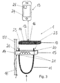
- the Figures 2 and 3 show the electronic fuse unit 1 with the main body 10 and with the lock body 11, and it is the receiving body 15 shown in arrangement on the two-wheeler 100, wherein the two-wheeled vehicle 100 is represented by, for example, a seat tube. Furthermore, the electrical line 18 is shown in sections, which is led out of the receiving body 15.
- a charging unit 16 which forms a primary charging unit 16
- a loading unit 17 which forms a secondary charging unit 17. If the main body 10 is brought into abutment flat against the receiving body 15, then the primary loading unit 16 and the secondary loading unit 17 are opposite one another with only a small distance. As a result, a magnetic coupling is achieved, whereby 10 electrical energy is transferable into the main body without contact.
- the main body 10 also has an energy store 14, which can be charged via the charging units 16 and 17 with energy from the energy source 19. Furthermore, a communication unit 12 is located in the main body 10, the, how FIG. 3 shows in detail, can communicate with a hand-held control unit 13, which control unit 13 is exemplified as a mobile phone 24.
- the control unit 13 may, for example, also be an other transceiver device in the manner of a motor vehicle key or the like.
- the lock body 11 is designed like a bow and has two free ends, which can be passed through through holes 20 in the receiving body 15, as in FIG. 3 shown.
- the ends of the bow-shaped lock body 11 projections 21 against which the receiving body 15 abuts when the lock body 11 is passed through the through holes 20.
- the ends of the bow-shaped lock body 11 from the receiving body 15, and on the ends of the base body 10 can be placed, as FIG. 3 indicated by arrows.
- An app 25 can be operated on the mobile telephone 24, which describes an application with which the mobile telephone 24 can communicate with the communication unit 12 in the base body 10.
- the locking unit 23 in the main body 10 can be controlled via the communication unit 12, and each end of the lock body 11 is associated with a locking unit 23 to block the ends of the bow-shaped lock body 11 within the body 10 or release.
- the locking unit 23 is also fed via the electrical energy storage 14, which can be charged via the charging units 16 and 17 when the base body 10 is in arrangement on the receiving body 15.
Landscapes
- Engineering & Computer Science (AREA)
- Mechanical Engineering (AREA)
- Lock And Its Accessories (AREA)
Abstract
Description
- Die vorliegende Erfindung betrifft eine elektronische Sicherungseinheit für ein Zweirad, aufweisend einen Grundkörper und einen Schlosskörper, der in einem Öffnungszustand vom Grundkörper wenigstens teilweise lösbar ist und der in einem Schließzustand am Grundkörper verriegelbar ist, und wobei im Grundkörper eine elektronische Kommunikationseinheit eingerichtet ist, die zur Kommunikation mit einem handhaltbaren Steuergerät ausgebildet ist, mittels dem die Sicherungseinheit wenigstens vom Schließzustand in den Öffnungszustand überführbar ist, und wobei im Grundkörper ein Energiespeicher zur Energieversorgung wenigstens der Kommunikationseinheit vorgesehen ist.
- Eine elektronische Sicherungseinheit für ein Zweirad ist beispielsweise aus der
DE 20 2014 005 564 U1 bekannt. Die elektronische Sicherungseinheit ist zur Sperrung eines Tretlagers eines Fahrrades ausgebildet und im Rahmen des Fahrrades integriert. Zur Kommunikation mit einem handhaltbaren Steuergerät weist die Sicherungseinheit eine Kommunikationseinheit auf. Zudem weist die Sicherungseinheit einen Energiespeicher auf, um wenigstens die Kommunikationseinheit mit Energie zu versorgen. Die bekannte elektronische Sicherungseinheit dient zur Sperrung des Fahrrades, so dass dieses nicht benutzt werden kann, die elektronische Sicherungseinheit ist jedoch nicht derart ausgebildet, dass diese ein Wegtragen des Fahrrades verhindern kann. - Häufig ist die Energiebereitstellung für eine Kommunikationseinheit einer elektronischen Sicherungseinheit die Schwierigkeit bei der Bereitstellung einer Sicherungseinheit, insbesondere wenn diese beweglich ist und vom Zweirad entnommen werden kann. Ein regelmäßiges Aufladen eines Energiespeichers einer Sicherungseinheit beispielsweise mit oder auf einem Ladegerät ist dann nicht vorteilhaft, wenn die elektronische Sicherungseinheit grundsätzlich am Fahrrad verbleiben muss, insbesondere dann, wenn das Fahrrad abgestellt wird und die elektronische Sicherungseinheit zur Sicherung des Fahrrades eingesetzt werden soll.
- Ein weiteres Ausführungsbeispiel einer elektronischen Sicherungseinheit ist aus der
EP 1 818 246 A2 bekannt. Die Druckschrift lehrt die Ausbildung einer elektronischen Sicherungseinheit als Ringschloss zur Sicherung des Hinterrades eines Fahrrades, und in an sich bekannter Weise weist die Sicherungseinheit einen drehbaren Bügel auf, der als Bolzen zwischen die Speichen des Hinterrades eingefahren werden kann. Damit ist auch diese Sicherungseinheit fest mit dem Fahrrad verbunden und kann ein Wegtragen des Fahrrades nicht verhindern. Der Vorteil elektronischer Sicherungseinheiten liegt ferner darin, dass das handhaltbare Steuergerät als Mobiltelefon ausgeführt werden kann, so dass für die Sicherungseinheit kein mechanisch wirkender Schlüssel mitgetragen werden muss, ferner muss kein Sicherungscode auswendig gelernt werden. - Als weiteres Ausführungsbeispiel zeigt die
DE 10 2004 054 331 A1 eine elektronische Sicherungseinheit für ein Fahrrad mit einem Schlosskörper in Form einer Kabelkonstruktion, und die Kabelkonstruktion kann in ein Loch eines Schlosskastens eingesteckt werden, welcher Schlosskasten einen Grundkörper der Sicherungseinheit bildet. In der Sicherungseinheit ist eine Kommunikationseinheit aufgenommen, die mit einem handhaltbaren Bedienelement kommunizieren kann, um das Schloss zwischen einem Öffnungszustand und einem Schließzustand zu wechseln. Nachteilhafterweise weist die elektronische Sicherungseinheit eine Vielzahl von Öffnungen, Löchern und Einzelteilen auf, die am Rahmen des Fahrrades montiert sind, so dass die Sicherungseinheit manipulationsanfällig ist. - Aufgabe der Erfindung ist die Weiterbildung einer elektronischen Sicherungseinheit für ein Zweirad, die mit einem handhaltbaren Steuergerät bedient werden kann, und die vom Fahrrad gelöst werden kann. Dabei soll die elektronische Sicherungseinheit mit Bezug auf eine Energieversorgung ortsunabhängig benutzt werden können.
- Diese Aufgabe wird ausgehend von einer elektronischen Sicherungseinheit für ein Zweirad gemäß dem Oberbegriff des Anspruches 1 mit den jeweils kennzeichnenden Merkmalen gelöst. Vorteilhafte Weiterbildungen der Erfindung sind in den abhängigen Ansprüchen angegeben.
- Die Erfindung schließt die technische Lehre ein, dass die elektronische Sicherungseinheit einen Aufnahmekörper umfasst, wobei der Grundkörper zur haltenden Aufnahme an eine erste Seite des Aufnahmekörpers anordbar ist und durch den der Schlosskörper zur Verriegelung am Grundkörper vor einer gegenüberliegenden zweiten Seite des Aufnahmekörpers hindurchführbar ist, und wobei im Aufnahmekörper eine Ladeeinheit aufgenommen ist, über die der Energiespeicher kabellos aufladbar ist, wenn der Grundkörper am Aufnahmekörper angeordnet ist.
- Kern der Erfindung ist ein Aufnahmekörper, welcher zwei Funktionen erfüllt. Eine erste Funktion erfüllt der Aufnahmekörper mit der haltenden Aufnahme des Grundkörpers, und wenn der Schlosskörper am Grundkörper verriegelt ist, nimmt der Aufnahmekörper den Grundkörper und den Schlosskörper verliersicher auf. Eine weitere Funktion erfüllt der Aufnahmekörper mit der integrierten Ladeeinheit, über die der Energiespeicher des Grundkörpers kabellos aufladbar ist. Das Aufladen kann dann erfolgen, wenn der Grundkörper am Aufnahmekörper angeordnet ist.
- Entriegelt beispielsweise ein Benutzer des Zweirades die elektronische Sicherungseinheit, so wird der Benutzer den Grundkörper an den Aufnahmekörper anordnen und mit dem Schlosskörper verriegeln. Bewegt der Benutzer das Zweirad, so wird der Energiespeicher über die Ladeeinheit im Aufnahmekörper aufgeladen. Der Energiespeicher ist beispielsweise ein Akkumulator und kann innerhalb eines Gehäuses des Grundkörpers aufgenommen sein.
- Durch das kabellose Aufladen des Energiespeichers muss der Grundkörpers nicht mit Steckverbindern und dergleichen ausgeführt werden. Weiterhin weist der Grundkörper keine Schnittstelle für einen Schlüssel auf, da die Kommunikationseinheit mit dem handhaltbaren Steuergerät über eine Funkverbindung kommuniziert. Im Ergebnis wird der Vorteil erreicht, dass die elektronische Sicherungseinheit frei von Öffnungen ausgeführt werden kann, wodurch ein besonderer Widerstand gegen eine Manipulation geschaffen wird. Insbesondere entsteht mit der Ausgestaltung des Grundkörpers der Vorteil, dass das Gehäuse des Grundkörpers ohne Öffnungen vollständig geschlossen und damit hermetisch dicht ausgeführt werden kann. Der Grundkörper muss lediglich die Möglichkeit bieten, den Schlosskörper am Grundkörper zu verriegeln, ein Schließsystem für einen Schlüssel oder ein Ladestecker für die Aufladung des Energiespeichers können mit der erfindungsgemäßen elektronischen Sicherungseinheit jedoch entfallen.
- Nach einer weiteren vorteilhaften Ausführungsform der elektronischen Sicherungseinheit ist im Grundkörper eine Ladeeinheit aufgenommen, wobei die Ladeeinheit im Aufnahmekörper eine primäre Ladeeinheit und wobei die Ladeeinheit im Grundkörper eine sekundäre Ladeeinheit bildet, welche Ladeeinheiten elektronmagnetisch miteinander koppelbar sind. Insbesondere dann, wenn der Grundkörper quaderförmig ausgeführt ist, kann dieser an den ebenfalls quaderförmig ausgeführten Aufnahmekörper angeordnet werden, so dass beide Körper eine jeweilige Planfläche aufweisen, die aufeinander liegen. Beispielsweise weist die primäre Ladeeinheit eine Spule auf, die elektromagnetisch gekoppelt wird mit einer Spule, die die sekundäre Ladeeinheit aufweist. Das Prinzip der elektromagnetischen Kopplung ist beispielsweise auch bei elekteischen Haushalts- und Hygienegeräten bekannt, und die Haushaltsgeräte weisen in der Regel einen entnehmbaren Teil auf, der von einer Aufnahmestation entnommen und auf diese wieder aufgesetzt werden kann. Die elektromagnetische Kopplung zwischen der primären Ladeeinheit im stationären Teil und der sekundären Ladeeinheit im entnehmbaren Teil wird immer dann erzeugt, wenn der entnehmbare Teil auf den stationären Teil aufgesetzt wird.
- Weiterhin ist es von Vorteil, wenn der Aufnahmekörper über eine elektrische Leitung mit einer Energiequelle verbunden ist. Der Aufnahmekörper ist insbesondere fest am Rahmen des Zweirades angeordnet, beispielsweise eines Fahrrades oder eines Motorrades. Beispielsweise kann das Fahrrad einen Nabendynamo aufweisen, und der Aufnahmekörper ist über eine elektrische Leitung mit dem Nabendynamo verbunden, beispielsweise auf gleiche Weise wie die Beleuchtung eines Fahrrades. Bewegt der Benutzer das Zweirad, so wird über die Energiequelle, also beispielsweise den Nabendynamo, elektrische Energie bereitgestellt, und über die elektromagnetische Kopplung der Ladeeinheiten wird der Energiespeicher mit der Energie aus der Energiequelle geladen. Beispielsweise ist die Energiequelle durch einen Dynamo des Zweirades gebildet, beispielsweise eines Fahrrades. Dient das elektronische Sicherungsmittel für ein Kraftrad, so kann die Energiequelle durch eine Batterie des Kraftrades gebildet sein, sofern vorhanden.
- Gemäß einer vorteilhaften Ausführung der Sicherungseinheit ist der Schlosskörper bügelförmig ausgebildet, wobei der Aufnahmekörper zur Hindurchführung des bügelförmigen Schlosskörpers Durchgangsöffnungen aufweist. Alternativ ist der Schlosskörper flexibel ausgebildet, beispielsweise als Stahlseil, als Kette oder mit mehreren drehbeweglichen Gliedern versehen, wobei den Ausführungen des Schlosskörpers zwei Enden gemeinsam sind, die durch Durchgangsöffnungen im Aufnahmekörper hindurchgeführt werden können. Das Hindurchführen der Enden des Schlosskörpers durch die Durchgangsöffnungen erfolgt von einer Seite, die der Seite gegenüberliegt, an der der Grundkörper der Sicherungseinheit am Aufnahmekörper anliegt. Die Enden des Schlosskörpers werden dabei im Grundkörper verriegelt, so dass schließlich eine verliersichere, haltende Anordnung des Grundkörpers und des Schlosskörpers am Aufnahmekörper möglich ist.
- Weiterführend weist der bügelförmige Schlosskörper Anformungen auf, die derart ausgebildet sind, dass der Aufnahmekörper zwischen dem Grundkörper und den Anformungen im Schließzustand der Sicherungseinheit eingefasst ist. Damit wird verhindert, dass der bügelförmige Schlosskörper durch die Durchgangsöffnungen im Aufnahmekörper weiter hindurchrutscht, und der Grundkörper und der Schlosskörper sind im Wesentlichen unbeweglich, starr mit dem Aufnahmekörper verbunden, wenn der Schlosskörper im Grundkörper verriegelt ist.
- Der Aufnahmekörper ist beispielsweise zur Anordnung an einem Rahmen des Zweirades ausgebildet. Beispielsweise kann der Aufnahmekörper an dem Sattelrohr angebracht werden, und der bügelförmige Schlosskörper erstreckt sich in der Ebene des Rahmens des Zweirades, um bei der Benutzung des Zweirades möglichst nicht zu stören.
- Im Grundkörper ist eine elektrische Verriegelungseinheit vorgesehen, mit der die Enden des bügelförmigen Schlosskörpers im Grundkörper verriegelbar sind. Die elektrische Verriegelungseinheit ist wie auch die Kommunikationseinheit mit dem Energiespeicher verbunden und kann über diesen elektrisch betätigt werden, um den Schlosskörper am Grundkörper zu verriegeln und freizugeben, und um wechselweise den Schließzustand oder den Öffnungszustand der elektronischen Sicherungseinheit herbeizuführen. Die elektrische Verriegelungseinheit kann beispielsweise einen Hubmagneten oder einen Stellmotor umfassen, um wenigstens einen Verriegelungsbolzen innerhalb des Grundkörpers zu bewegen, mit dem die Enden des Schlosskörpers formschlüssig im Grundkörper blockiert und freigegeben werden können. Die elektrische Verriegelungseinheit kann insbesondere angesprochen werden über die Kommunikationseinheit und damit über das handhaltbare Steuergerät.
- Das handhaltbare Steuergerät ist gemäß einem weiterführenden Ausführungsbeispiel mittels eines Mobiltelefons gebildet, wobei die Kommunikationseinheit zur Kommunikation mit dem Mobiltelefon ausgebildet ist. Die Kommunikation zwischen der Kommunikationseinheit und dem handhaltbaren Steuergerät kann beispielsweise ein elektronisches Pairing zum Austausch geheimer elektronischer Schlüssel umfassen. Dabei ist es denkbar, dass das Mobiltelefon eine App aufweist und dass diese auf dem Mobiltelefon betreibbar ist, und über die schließlich die Sicherungseinheit zur Sicherung des Zweirades ansteuerbar ist, insbesondere um diese zwischen dem Schließzustand und dem Öffnungszustand hin und herzu schalten.
- Gemäß einer Weiterführung der Kommunikation zwischen dem handhaltbaren Steuergerät und der Kommunikationseinheit kann ferner vorgesehen sein, dass die Kommunikationseinheit so ausgebildet ist, dass das Pairing ausführbar ist, wenn sich die Sicherungseinheit eine vorgebbare Mindestzeit im Öffnungszustand befindet. Der längere Öffnungszustand wird in der Regel nicht im gewöhnlichen Gebrauch der Sicherungseinheit herbeigeführt, da die Sicherungseinheit entweder in Anordnung am Aufnahmekörper geschlossen ist oder zum Abschließen des Zweirades ebenfalls geschlossen ist. Beispielsweise kann also vorgesehen sein, das Pairing erst dann ausführbar zu machen, wenn der Öffnungszustand deutlich länger vorliegt als beim regelmäßigen Gebrauch. Der länger vorliegende Öffnungszustand liegt dabei insbesondere dann vor, wenn sich die elektronische Sicherungseinheit im Besitz eines berechtigten Eigentümers befindet.
- Weitere, die Erfindung verbessernde Maßnahmen werden nachstehend gemeinsam mit der Beschreibung eines bevorzugten Ausführungsbeispiels der Erfindung anhand der Figuren näher dargestellt. Es zeigt:
- Figur 1
- eine Ansicht eines Fahrrades mit einer elektronischen Sicherungseinheit mit den Merkmalen der vorliegenden Erfindung,
- Figur 2
- die elektronische Sicherungseinheit mit dem Grundkörper und mit dem Schlosskörper, welche entnommen ist vom Aufnahmekörper, der sich in Anordnung an einem Rahmenteil des Zweirades befindet, und
- Figur 3
- eine Ansicht des Schlosskörpers in Anordnung am Aufnahmekörper, wobei der Grundkörper vom Schlosskörper entnommen ist.
-
Figur 1 zeigt ein Zweirad 100 in Gestalt eines Fahrrades, und eine elektronische Sicherungseinheit 1 ist am Zweirad 100 angeordnet dargestellt. Die elektronische Sicherungseinheit 1 ist mit dem Grundkörper 10 und mit dem Schlosskörper 11 gezeigt, und der Grundkörper 10 und der Schlosskörper 11 befinden sich in Anordnung am Aufnahmekörper 15. Damit sichert die Sicherungseinheit 1 das Zweirad 100 im gezeigten Zustand nicht und befindet sich am Aufnahmekörper 15, um das Zweirad 100 zu bewegen. - Die Darstellung zeigt den Aufnahmekörper 15 in Anordnung am Rahmen des Zweirades 100, und das Zweirad 100 weist eine Energiequelle 19 in Form eines Nabendynamos auf. Zwischen der Energiequelle 19 und dem Aufnahmekörper 15 erstreckt sich eine elektrische Leitung 18, und wird das Zweirad 100 bewegt, so wird über den Aufnahmekörper 15 elektrische Energie aus der Energiequelle 19 zur Verfügung gestellt.
- Die
Figuren 2 und3 zeigen die elektronische Sicherungseinheit 1 mit dem Grundkörper 10 und mit dem Schlosskörper 11, und es ist der Aufnahmekörper 15 in Anordnung am Zweirad 100 gezeigt, wobei das Zweirad 100 durch beispielsweise eine Sattelrohrstange wiedergegeben ist. Weiterhin ist die elektrische Leitung 18 abschnittsweise gezeigt, die aus dem Aufnahmekörper 15 herausgeführt ist. - Im Aufnahmekörper 15 befindet sich eine Ladeeinheit 16, die eine primäre Ladeeinheit 16 bildet, und im Grundkörper 10 befindet sich eine Ladeeinheit 17, die eine sekundäre Ladeeinheit 17 bildet. Wird der Grundkörper 10 plan an dem Aufnahmekörper 15 zur Anlage gebracht, so liegen sich die primäre Ladeeinheit 16 und die sekundäre Ladeeinheit 17 mit nur geringem Abstand gegenüber. Dadurch wird eine magnetische Kopplung erreicht, wodurch berührungslos in den Grundkörper 10 elektrische Energie übertragbar ist.
- Der Grundkörper 10 weist weiterhin einen Energiespeicher 14 auf, der über die Ladeeinheiten 16 und 17 mit Energie aus der Energiequelle 19 geladen werden kann. Weiterhin befindet sich im Grundkörper 10 eine Kommunikationseinheit 12, die, wie
Figur 3 im Detail zeigt, mit einem handhaltbaren Steuergerät 13 kommunizieren kann, welches Steuergerät 13 beispielhaft als Mobiltelefon 24 ausgebildet ist. Die Steuereinheit 13 kann beispielsweise auch ein sonstiges Sende-Empfangs-Gerät nach Art eines KfZ-Schlüssels oder dergleichen sein. - Der Schlosskörper 11 ist bügelartig ausgeführt und weist zwei freie Enden auf, die durch Durchgangsöffnungen 20 im Aufnahmekörper 15 hindurchgeführt werden können, wie in
Figur 3 gezeigt. Um einen Anschlag zu bilden, weisen die Enden des bügelförmigen Schlosskörpers 11 Anformungen 21 auf, an die der Aufnahmekörper 15 anschlägt, wenn der Schlosskörper 11 durch die Durchgangsöffnungen 20 hindurchgeführt ist. Auf der gegenüberliegenden Seite ragen die Enden des bügelförmigen Schlossskörpers 11 aus dem Aufnahmekörper 15 hervor, und auf die Enden kann der Grundkörper 10 aufgesetzt werden, wieFigur 3 mit Pfeilen angedeutet zeigt. - Auf dem Mobiltelefon 24 ist eine App 25 betreibbar, die eine Applikation beschreibt, mit der mittels des Mobiltelefons 24 mit der Kommunikationseinheit 12 im Grundkörper 10 kommuniziert werden kann. Mit der App 25 kann über die Kommunikationseinheit 12 die Verriegelungseinheit 23 im Grundkörper 10 angesteuert werden, und jedem Ende des Schlosskörpers 11 ist eine Verriegelungseinheit 23 zugeordnet, um die Enden des bügelförmigen Schlosskörpers 11 innerhalb des Grundkörpers 10 zu blockieren oder freizugeben. Die Verriegelungseinheit 23 wird dabei ebenfalls über den elektrischen Energiespeicher 14 gespeist, der über die Ladeeinheiten 16 und 17 aufgeladen werden kann, wenn sich der Grundkörper 10 in Anordnung am Aufnahmekörper 15 befindet.
- Die Erfindung beschränkt sich in ihrer Ausführung nicht auf das vorstehend angegebene bevorzugte Ausführungsbeispiel. Vielmehr ist eine Anzahl von Varianten denkbar, welche von der dargestellten Lösung auch bei grundsätzlich anders gearteten Ausführungen Gebrauch macht. Sämtliche aus den Ansprüchen, der Beschreibung oder den Zeichnungen hervorgehenden Merkmale und/oder Vorteile, einschließlich konstruktiver Einzelheiten oder räumlicher Anordnungen, können sowohl für sich als auch in den verschiedensten Kombinationen erfindungswesentlich sein.
-
- 100
- Zweirad
- 1
- elektronische Sicherungseinheit
- 10
- Grundkörper
- 11
- Schlosskörper
- 12
- Kommunikationseinheit
- 13
- Steuergerät
- 14
- Energiespeicher
- 15
- Aufnahmekörper
- 16
- primäre Ladeeinheit
- 17
- sekundäre Ladeeinheit
- 18
- elektrische Leitung
- 19
- Energiequelle
- 20
- Durchgangsöffnung
- 21
- Anformung
- 22
- Rahmen
- 23
- Verriegelungseinheit
- 24
- Mobiltelefon
- 25
- APP
Claims (12)
- Elektronische Sicherungseinheit (1) für ein Zweirad (100), aufweisend einen Grundkörper (10) und einen Schlosskörper (11), der in einem Öffnungszustand vom Grundkörper (10) wenigstens teilweise lösbar ist und der in einem Schließzustand am Grundkörper (10) verriegelbar ist, und wobei im Grundkörper (10) eine elektronische Kommunikationseinheit (12) eingerichtet ist, die zur Kommunikation mit einem handhaltbaren Steuergerät (13) ausgebildet ist, mittels dem die Sicherungseinheit (1) wenigstens vom Schließzustand in den Öffnungszustand überführbar ist, und wobei im Grundkörper (10) ein Energiespeicher (14) zur Energieversorgung wenigstens der Kommunikationseinheit (12) vorgesehen ist, dadurch gekennzeichnet, dass die elektronische Sicherungseinheit (1) einen Aufnahmekörper (15) umfasst, wobei der Grundkörper (10) zur haltenden Aufnahme an eine erste Seite des Aufnahmekörpers (15) anordbar ist und durch den der Schlosskörper (11) zur Verriegelung am Grundkörper (10) von einer gegenüberliegenden zweiten Seite des Aufnahmekörpers (15) hindurchführbar ist, und wobei im Aufnahmekörper (15) eine Ladeeinheit (16) aufgenommen ist, über die der Energiespeicher (14) kabellos aufladbar ist, wenn der Grundkörper (10) am Aufnahmekörper (15) angeordnet ist.
- Elektronische Sicherungseinheit (1) nach Anspruch 1, dadurch gekennzeichnet, dass im Grundkörper (10) eine Ladeeinheit (17) aufgenommen ist, wobei die Ladeeinheit (16) im Aufnahmekörper (15) eine primäre Ladeeinheit (16) und wobei die Ladeeinheit (17) im Grundkörper (10) eine sekundäre Ladeeinheit (17) bildet, welche Ladeeinheiten (16, 17) elektromagnetisch miteinander koppelbar sind.
- Elektronische Sicherungseinheit (1) nach Anspruch 1 oder 2, dadurch gekennzeichnet, dass der Aufnahmekörper (15) über eine elektrische Leitung (18) mit einer Energiequelle (19) verbunden ist.
- Elektronische Sicherungseinheit (1) nach Anspruch 3, dadurch gekennzeichnet, dass die Energiequelle (19) durch einen Dynamo des Zweirades (100) gebildet ist.
- Elektronische Sicherungseinheit (1) nach einem der vorgenannten Ansprüche, dadurch gekennzeichnet, dass der Schlosskörper (11) bügelförmig ausgebildet ist und wobei der Aufnahmekörper (15) zur Hindurchführung des bügelförmigen Schlosskörpers (11) Durchgangsöffnungen (20) aufweist.
- Elektronische Sicherungseinheit (1) nach einem der vorgenannten Ansprüche, dadurch gekennzeichnet, dass der bügelförmige Schlosskörper (11) Anformungen (21) aufweist, die derart ausgebildet sind, dass der Aufnahmekörper (15) zwischen dem Grundkörper (10) und den Anformungen (21) im Schließzustand der Sicherungseinheit (1) eingefasst ist.
- Elektronische Sicherungseinheit (1) nach einem der vorgenannten Ansprüche, dadurch gekennzeichnet, dass der Aufnahmekörper (15) zur Anordnung an einem Rahmen (22) des Zweirades (100) ausgebildet ist.
- Elektronische Sicherungseinheit (1) nach einem der vorgenannten Ansprüche, dadurch gekennzeichnet, dass im Grundkörper (10) eine elektrische Verriegelungseinheit (23) vorgesehen ist, mit der die Enden des bügelförmigen Schlosskörpers (11) im Grundkörper (10) verriegelbar sind.
- Elektronische Sicherungseinheit (1) nach einem der vorgenannten Ansprüche, dadurch gekennzeichnet, dass das handhaltbare Steuergerät (13) mittels eines Mobiltelefons (24) gebildet ist, und dass die Kommunikationseinheit (12) zur Kommunikation mit dem Mobiltelefon (24) ausgebildet ist.
- Elektronische Sicherungseinheit (1) nach einem der vorgenannten Ansprüche, dadurch gekennzeichnet, dass die Kommunikation zwischen der Kommunikationseinheit (12) und dem handhaltbaren Steuergerät (13) ein elektronisches Pairing zum Austausch geheimer elektronischer Schlüssel umfasst.
- Elektronische Sicherungseinheit (1) nach Anspruch 10, dadurch gekennzeichnet, dass die Kommunikationseinheit (12) so ausgebildet ist, dass das Pairing ausführbar ist, wenn sich die Sicherungseinheit (1) eine vorgebbare Mindestzeit im Öffnungszustand befindet.
- Zweirad (100) mit einer elektronischen Sicherungseinheit (1) nach einem der Ansprüche 1 bis 11, dadurch gekennzeichnet, dass der Aufnahmekörper (15) Bestandteil des Zweirades (100) ist.
Priority Applications (2)
| Application Number | Priority Date | Filing Date | Title |
|---|---|---|---|
| EP15199837.4A EP3181434B1 (de) | 2015-12-14 | 2015-12-14 | Elektronisches sicherungsschloss |
| PCT/EP2016/080060 WO2017102496A1 (de) | 2015-12-14 | 2016-12-07 | Elektronisches sicherungsschloss |
Applications Claiming Priority (1)
| Application Number | Priority Date | Filing Date | Title |
|---|---|---|---|
| EP15199837.4A EP3181434B1 (de) | 2015-12-14 | 2015-12-14 | Elektronisches sicherungsschloss |
Publications (2)
| Publication Number | Publication Date |
|---|---|
| EP3181434A1 true EP3181434A1 (de) | 2017-06-21 |
| EP3181434B1 EP3181434B1 (de) | 2018-03-21 |
Family
ID=54979401
Family Applications (1)
| Application Number | Title | Priority Date | Filing Date |
|---|---|---|---|
| EP15199837.4A Active EP3181434B1 (de) | 2015-12-14 | 2015-12-14 | Elektronisches sicherungsschloss |
Country Status (1)
| Country | Link |
|---|---|
| EP (1) | EP3181434B1 (de) |
Citations (6)
| Publication number | Priority date | Publication date | Assignee | Title |
|---|---|---|---|---|
| DE20211241U1 (de) * | 2002-02-14 | 2002-11-21 | Weierstahl, Rudolf, 47877 Willich | Fahrradschloss mit Fernauslöser |
| DE102004054331A1 (de) | 2003-11-10 | 2005-06-23 | Van Der Veer Designers B.V. | Fahrradschloss |
| EP1818246A2 (de) | 2006-02-14 | 2007-08-15 | ABUS August Bremicker Söhne KG | Elektronisches Fahrradschloss |
| FR2934984A1 (fr) * | 2008-08-18 | 2010-02-19 | Dominique Delaunay | Support de cadenas anti-vol de moto |
| DE202014005564U1 (de) | 2014-07-08 | 2014-07-31 | Petz Friedrich | Elektronisches Fahrradschloß am Tretlager |
| EP2865835A2 (de) * | 2013-10-24 | 2015-04-29 | Bluequar Technologies UG (haftungsbeschränkt) | Digitales Verschlussmittel |
-
2015
- 2015-12-14 EP EP15199837.4A patent/EP3181434B1/de active Active
Patent Citations (6)
| Publication number | Priority date | Publication date | Assignee | Title |
|---|---|---|---|---|
| DE20211241U1 (de) * | 2002-02-14 | 2002-11-21 | Weierstahl, Rudolf, 47877 Willich | Fahrradschloss mit Fernauslöser |
| DE102004054331A1 (de) | 2003-11-10 | 2005-06-23 | Van Der Veer Designers B.V. | Fahrradschloss |
| EP1818246A2 (de) | 2006-02-14 | 2007-08-15 | ABUS August Bremicker Söhne KG | Elektronisches Fahrradschloss |
| FR2934984A1 (fr) * | 2008-08-18 | 2010-02-19 | Dominique Delaunay | Support de cadenas anti-vol de moto |
| EP2865835A2 (de) * | 2013-10-24 | 2015-04-29 | Bluequar Technologies UG (haftungsbeschränkt) | Digitales Verschlussmittel |
| DE202014005564U1 (de) | 2014-07-08 | 2014-07-31 | Petz Friedrich | Elektronisches Fahrradschloß am Tretlager |
Also Published As
| Publication number | Publication date |
|---|---|
| EP3181434B1 (de) | 2018-03-21 |
Similar Documents
| Publication | Publication Date | Title |
|---|---|---|
| EP3567193B1 (de) | Mobiles schloss | |
| DE102018006690A1 (de) | Fahrzeug | |
| DE102014102197B4 (de) | Steckverbinderteil mit einem Rastelement | |
| EP2673862B1 (de) | Ladestation und verfahren zur sicherung eines ladevorgangs eines elektrofahrzeugs | |
| EP2454117B1 (de) | Verfahren zur kommunikation zwischen einem elektrofahrzeug und einer ladestelle zum elektrischen laden zumindest eines energiespeichers des elektrofahrzeugs | |
| EP3507131B1 (de) | Lade- und absperrvorrichtung für elektrofahrzeuge | |
| DE102013112991A1 (de) | Ladestecker zum Laden eines Elektrofahrzeugs | |
| DE102013204904A1 (de) | Ladekabelschloss für ein Elektrofahrzeug | |
| EP2261167A1 (de) | Flurförderzeug mit einer Batterieeinheit | |
| WO2011023187A2 (de) | Schloss | |
| WO2016075121A1 (de) | Sicherheitsschloss | |
| DE102018114399A1 (de) | Vorrichtung zum Kuppeln einer elektrischen Ladeeinrichtung mit einem Akkumulator eines elektrisch antreibbaren, einspurigen Fahrzeugs | |
| DE202016008424U1 (de) | Lade- und Überwachungssystem zum Aufladen einer Stromspeichervorrichtung für Elektrozweiräder | |
| EP3565743B1 (de) | Sicherungsanordnung und -verfahren für elektrofahrräder | |
| DE102015121715A1 (de) | Elektronisches Sicherungsschloss | |
| DE19822865B4 (de) | Schließzylinder | |
| DE102011083031A1 (de) | Verriegelungsvorrichtung | |
| EP3486972B1 (de) | Batteriesystem | |
| DE102015002486A1 (de) | Fahrzeug | |
| DE102015113874A1 (de) | Steckverbinderteil mit einem Verriegelungselement | |
| EP3181434B1 (de) | Elektronisches sicherungsschloss | |
| WO2017102496A1 (de) | Elektronisches sicherungsschloss | |
| EP2865835B1 (de) | Digitales Verschlussmittel | |
| DE102008056546B4 (de) | Entleihsystem für Fahrräder | |
| DE202016002087U1 (de) | Elektronisches Fahrradschloss |
Legal Events
| Date | Code | Title | Description |
|---|---|---|---|
| PUAI | Public reference made under article 153(3) epc to a published international application that has entered the european phase |
Free format text: ORIGINAL CODE: 0009012 |
|
| 17P | Request for examination filed |
Effective date: 20161207 |
|
| AK | Designated contracting states |
Kind code of ref document: A1 Designated state(s): AL AT BE BG CH CY CZ DE DK EE ES FI FR GB GR HR HU IE IS IT LI LT LU LV MC MK MT NL NO PL PT RO RS SE SI SK SM TR |
|
| AX | Request for extension of the european patent |
Extension state: BA ME |
|
| GRAJ | Information related to disapproval of communication of intention to grant by the applicant or resumption of examination proceedings by the epo deleted |
Free format text: ORIGINAL CODE: EPIDOSDIGR1 |
|
| GRAP | Despatch of communication of intention to grant a patent |
Free format text: ORIGINAL CODE: EPIDOSNIGR1 |
|
| INTG | Intention to grant announced |
Effective date: 20171129 |
|
| GRAS | Grant fee paid |
Free format text: ORIGINAL CODE: EPIDOSNIGR3 |
|
| GRAA | (expected) grant |
Free format text: ORIGINAL CODE: 0009210 |
|
| AK | Designated contracting states |
Kind code of ref document: B1 Designated state(s): AL AT BE BG CH CY CZ DE DK EE ES FI FR GB GR HR HU IE IS IT LI LT LU LV MC MK MT NL NO PL PT RO RS SE SI SK SM TR |
|
| REG | Reference to a national code |
Ref country code: GB Ref legal event code: FG4D Free format text: NOT ENGLISH |
|
| REG | Reference to a national code |
Ref country code: CH Ref legal event code: EP |
|
| REG | Reference to a national code |
Ref country code: NL Ref legal event code: FP |
|
| REG | Reference to a national code |
Ref country code: AT Ref legal event code: REF Ref document number: 980777 Country of ref document: AT Kind code of ref document: T Effective date: 20180415 |
|
| REG | Reference to a national code |
Ref country code: IE Ref legal event code: FG4D Free format text: LANGUAGE OF EP DOCUMENT: GERMAN |
|
| REG | Reference to a national code |
Ref country code: DE Ref legal event code: R096 Ref document number: 502015003531 Country of ref document: DE |
|
| RIN2 | Information on inventor provided after grant (corrected) |
Inventor name: LUDWIG, THERESA Inventor name: WAGNER, JENS |
|
| REG | Reference to a national code |
Ref country code: DE Ref legal event code: R083 Ref document number: 502015003531 Country of ref document: DE |
|
| PG25 | Lapsed in a contracting state [announced via postgrant information from national office to epo] |
Ref country code: FI Free format text: LAPSE BECAUSE OF FAILURE TO SUBMIT A TRANSLATION OF THE DESCRIPTION OR TO PAY THE FEE WITHIN THE PRESCRIBED TIME-LIMIT Effective date: 20180321 Ref country code: NO Free format text: LAPSE BECAUSE OF FAILURE TO SUBMIT A TRANSLATION OF THE DESCRIPTION OR TO PAY THE FEE WITHIN THE PRESCRIBED TIME-LIMIT Effective date: 20180621 Ref country code: CY Free format text: LAPSE BECAUSE OF FAILURE TO SUBMIT A TRANSLATION OF THE DESCRIPTION OR TO PAY THE FEE WITHIN THE PRESCRIBED TIME-LIMIT Effective date: 20180321 Ref country code: LT Free format text: LAPSE BECAUSE OF FAILURE TO SUBMIT A TRANSLATION OF THE DESCRIPTION OR TO PAY THE FEE WITHIN THE PRESCRIBED TIME-LIMIT Effective date: 20180321 Ref country code: HR Free format text: LAPSE BECAUSE OF FAILURE TO SUBMIT A TRANSLATION OF THE DESCRIPTION OR TO PAY THE FEE WITHIN THE PRESCRIBED TIME-LIMIT Effective date: 20180321 |
|
| REG | Reference to a national code |
Ref country code: LT Ref legal event code: MG4D |
|
| PG25 | Lapsed in a contracting state [announced via postgrant information from national office to epo] |
Ref country code: GR Free format text: LAPSE BECAUSE OF FAILURE TO SUBMIT A TRANSLATION OF THE DESCRIPTION OR TO PAY THE FEE WITHIN THE PRESCRIBED TIME-LIMIT Effective date: 20180622 Ref country code: RS Free format text: LAPSE BECAUSE OF FAILURE TO SUBMIT A TRANSLATION OF THE DESCRIPTION OR TO PAY THE FEE WITHIN THE PRESCRIBED TIME-LIMIT Effective date: 20180321 Ref country code: BG Free format text: LAPSE BECAUSE OF FAILURE TO SUBMIT A TRANSLATION OF THE DESCRIPTION OR TO PAY THE FEE WITHIN THE PRESCRIBED TIME-LIMIT Effective date: 20180621 Ref country code: SE Free format text: LAPSE BECAUSE OF FAILURE TO SUBMIT A TRANSLATION OF THE DESCRIPTION OR TO PAY THE FEE WITHIN THE PRESCRIBED TIME-LIMIT Effective date: 20180321 Ref country code: LV Free format text: LAPSE BECAUSE OF FAILURE TO SUBMIT A TRANSLATION OF THE DESCRIPTION OR TO PAY THE FEE WITHIN THE PRESCRIBED TIME-LIMIT Effective date: 20180321 |
|
| PG25 | Lapsed in a contracting state [announced via postgrant information from national office to epo] |
Ref country code: MT Free format text: LAPSE BECAUSE OF FAILURE TO SUBMIT A TRANSLATION OF THE DESCRIPTION OR TO PAY THE FEE WITHIN THE PRESCRIBED TIME-LIMIT Effective date: 20180321 |
|
| PG25 | Lapsed in a contracting state [announced via postgrant information from national office to epo] |
Ref country code: PL Free format text: LAPSE BECAUSE OF FAILURE TO SUBMIT A TRANSLATION OF THE DESCRIPTION OR TO PAY THE FEE WITHIN THE PRESCRIBED TIME-LIMIT Effective date: 20180321 Ref country code: EE Free format text: LAPSE BECAUSE OF FAILURE TO SUBMIT A TRANSLATION OF THE DESCRIPTION OR TO PAY THE FEE WITHIN THE PRESCRIBED TIME-LIMIT Effective date: 20180321 Ref country code: ES Free format text: LAPSE BECAUSE OF FAILURE TO SUBMIT A TRANSLATION OF THE DESCRIPTION OR TO PAY THE FEE WITHIN THE PRESCRIBED TIME-LIMIT Effective date: 20180321 Ref country code: RO Free format text: LAPSE BECAUSE OF FAILURE TO SUBMIT A TRANSLATION OF THE DESCRIPTION OR TO PAY THE FEE WITHIN THE PRESCRIBED TIME-LIMIT Effective date: 20180321 Ref country code: IT Free format text: LAPSE BECAUSE OF FAILURE TO SUBMIT A TRANSLATION OF THE DESCRIPTION OR TO PAY THE FEE WITHIN THE PRESCRIBED TIME-LIMIT Effective date: 20180321 Ref country code: AL Free format text: LAPSE BECAUSE OF FAILURE TO SUBMIT A TRANSLATION OF THE DESCRIPTION OR TO PAY THE FEE WITHIN THE PRESCRIBED TIME-LIMIT Effective date: 20180321 |
|
| PG25 | Lapsed in a contracting state [announced via postgrant information from national office to epo] |
Ref country code: SK Free format text: LAPSE BECAUSE OF FAILURE TO SUBMIT A TRANSLATION OF THE DESCRIPTION OR TO PAY THE FEE WITHIN THE PRESCRIBED TIME-LIMIT Effective date: 20180321 Ref country code: SM Free format text: LAPSE BECAUSE OF FAILURE TO SUBMIT A TRANSLATION OF THE DESCRIPTION OR TO PAY THE FEE WITHIN THE PRESCRIBED TIME-LIMIT Effective date: 20180321 Ref country code: CZ Free format text: LAPSE BECAUSE OF FAILURE TO SUBMIT A TRANSLATION OF THE DESCRIPTION OR TO PAY THE FEE WITHIN THE PRESCRIBED TIME-LIMIT Effective date: 20180321 |
|
| PG25 | Lapsed in a contracting state [announced via postgrant information from national office to epo] |
Ref country code: PT Free format text: LAPSE BECAUSE OF FAILURE TO SUBMIT A TRANSLATION OF THE DESCRIPTION OR TO PAY THE FEE WITHIN THE PRESCRIBED TIME-LIMIT Effective date: 20180723 |
|
| REG | Reference to a national code |
Ref country code: DE Ref legal event code: R097 Ref document number: 502015003531 Country of ref document: DE |
|
| PLBE | No opposition filed within time limit |
Free format text: ORIGINAL CODE: 0009261 |
|
| STAA | Information on the status of an ep patent application or granted ep patent |
Free format text: STATUS: NO OPPOSITION FILED WITHIN TIME LIMIT |
|
| PG25 | Lapsed in a contracting state [announced via postgrant information from national office to epo] |
Ref country code: DK Free format text: LAPSE BECAUSE OF FAILURE TO SUBMIT A TRANSLATION OF THE DESCRIPTION OR TO PAY THE FEE WITHIN THE PRESCRIBED TIME-LIMIT Effective date: 20180321 |
|
| 26N | No opposition filed |
Effective date: 20190102 |
|
| PG25 | Lapsed in a contracting state [announced via postgrant information from national office to epo] |
Ref country code: SI Free format text: LAPSE BECAUSE OF FAILURE TO SUBMIT A TRANSLATION OF THE DESCRIPTION OR TO PAY THE FEE WITHIN THE PRESCRIBED TIME-LIMIT Effective date: 20180321 |
|
| REG | Reference to a national code |
Ref country code: CH Ref legal event code: PL |
|
| PG25 | Lapsed in a contracting state [announced via postgrant information from national office to epo] |
Ref country code: MC Free format text: LAPSE BECAUSE OF FAILURE TO SUBMIT A TRANSLATION OF THE DESCRIPTION OR TO PAY THE FEE WITHIN THE PRESCRIBED TIME-LIMIT Effective date: 20180321 Ref country code: LU Free format text: LAPSE BECAUSE OF NON-PAYMENT OF DUE FEES Effective date: 20181214 |
|
| REG | Reference to a national code |
Ref country code: IE Ref legal event code: MM4A |
|
| REG | Reference to a national code |
Ref country code: BE Ref legal event code: MM Effective date: 20181231 |
|
| PG25 | Lapsed in a contracting state [announced via postgrant information from national office to epo] |
Ref country code: IE Free format text: LAPSE BECAUSE OF NON-PAYMENT OF DUE FEES Effective date: 20181214 |
|
| PG25 | Lapsed in a contracting state [announced via postgrant information from national office to epo] |
Ref country code: BE Free format text: LAPSE BECAUSE OF NON-PAYMENT OF DUE FEES Effective date: 20181231 |
|
| PG25 | Lapsed in a contracting state [announced via postgrant information from national office to epo] |
Ref country code: LI Free format text: LAPSE BECAUSE OF NON-PAYMENT OF DUE FEES Effective date: 20181231 Ref country code: CH Free format text: LAPSE BECAUSE OF NON-PAYMENT OF DUE FEES Effective date: 20181231 |
|
| PG25 | Lapsed in a contracting state [announced via postgrant information from national office to epo] |
Ref country code: TR Free format text: LAPSE BECAUSE OF FAILURE TO SUBMIT A TRANSLATION OF THE DESCRIPTION OR TO PAY THE FEE WITHIN THE PRESCRIBED TIME-LIMIT Effective date: 20180321 |
|
| PG25 | Lapsed in a contracting state [announced via postgrant information from national office to epo] |
Ref country code: MK Free format text: LAPSE BECAUSE OF NON-PAYMENT OF DUE FEES Effective date: 20180321 Ref country code: HU Free format text: LAPSE BECAUSE OF FAILURE TO SUBMIT A TRANSLATION OF THE DESCRIPTION OR TO PAY THE FEE WITHIN THE PRESCRIBED TIME-LIMIT; INVALID AB INITIO Effective date: 20151214 |
|
| PG25 | Lapsed in a contracting state [announced via postgrant information from national office to epo] |
Ref country code: IS Free format text: LAPSE BECAUSE OF FAILURE TO SUBMIT A TRANSLATION OF THE DESCRIPTION OR TO PAY THE FEE WITHIN THE PRESCRIBED TIME-LIMIT Effective date: 20180721 |
|
| REG | Reference to a national code |
Ref country code: AT Ref legal event code: MM01 Ref document number: 980777 Country of ref document: AT Kind code of ref document: T Effective date: 20201214 |
|
| PGFP | Annual fee paid to national office [announced via postgrant information from national office to epo] |
Ref country code: NL Payment date: 20211217 Year of fee payment: 7 |
|
| PG25 | Lapsed in a contracting state [announced via postgrant information from national office to epo] |
Ref country code: AT Free format text: LAPSE BECAUSE OF NON-PAYMENT OF DUE FEES Effective date: 20201214 |
|
| REG | Reference to a national code |
Ref country code: NL Ref legal event code: MM Effective date: 20230101 |
|
| PG25 | Lapsed in a contracting state [announced via postgrant information from national office to epo] |
Ref country code: NL Free format text: LAPSE BECAUSE OF NON-PAYMENT OF DUE FEES Effective date: 20230101 |
|
| PGFP | Annual fee paid to national office [announced via postgrant information from national office to epo] |
Ref country code: GB Payment date: 20251218 Year of fee payment: 11 |
|
| PGFP | Annual fee paid to national office [announced via postgrant information from national office to epo] |
Ref country code: FR Payment date: 20251218 Year of fee payment: 11 |
|
| PGFP | Annual fee paid to national office [announced via postgrant information from national office to epo] |
Ref country code: DE Payment date: 20251222 Year of fee payment: 11 |