EP3179770B1 - Équipement d'utilisateur - Google Patents
Équipement d'utilisateur Download PDFInfo
- Publication number
- EP3179770B1 EP3179770B1 EP15830364.4A EP15830364A EP3179770B1 EP 3179770 B1 EP3179770 B1 EP 3179770B1 EP 15830364 A EP15830364 A EP 15830364A EP 3179770 B1 EP3179770 B1 EP 3179770B1
- Authority
- EP
- European Patent Office
- Prior art keywords
- rlc
- base station
- processing unit
- layer processing
- establishment
- Prior art date
- Legal status (The legal status is an assumption and is not a legal conclusion. Google has not performed a legal analysis and makes no representation as to the accuracy of the status listed.)
- Active
Links
- 238000012545 processing Methods 0.000 claims description 125
- 230000005540 biological transmission Effects 0.000 claims description 58
- 238000004891 communication Methods 0.000 claims description 39
- 230000009977 dual effect Effects 0.000 claims description 17
- 238000012217 deletion Methods 0.000 description 21
- 230000037430 deletion Effects 0.000 description 21
- 238000010586 diagram Methods 0.000 description 14
- 230000008859 change Effects 0.000 description 12
- 238000000034 method Methods 0.000 description 8
- 230000002776 aggregation Effects 0.000 description 7
- 238000004220 aggregation Methods 0.000 description 7
- 239000000969 carrier Substances 0.000 description 6
- 230000011664 signaling Effects 0.000 description 6
- 230000006870 function Effects 0.000 description 5
- 230000004044 response Effects 0.000 description 5
- 230000004913 activation Effects 0.000 description 3
- 230000001960 triggered effect Effects 0.000 description 2
- 230000008901 benefit Effects 0.000 description 1
- 230000001419 dependent effect Effects 0.000 description 1
- 230000010365 information processing Effects 0.000 description 1
- 230000007774 longterm Effects 0.000 description 1
- 238000012986 modification Methods 0.000 description 1
- 230000004048 modification Effects 0.000 description 1
- 230000008569 process Effects 0.000 description 1
- 230000009467 reduction Effects 0.000 description 1
Images


Classifications
-
- H—ELECTRICITY
- H04—ELECTRIC COMMUNICATION TECHNIQUE
- H04W—WIRELESS COMMUNICATION NETWORKS
- H04W76/00—Connection management
- H04W76/20—Manipulation of established connections
- H04W76/25—Maintenance of established connections
-
- H—ELECTRICITY
- H04—ELECTRIC COMMUNICATION TECHNIQUE
- H04W—WIRELESS COMMUNICATION NETWORKS
- H04W16/00—Network planning, e.g. coverage or traffic planning tools; Network deployment, e.g. resource partitioning or cells structures
- H04W16/24—Cell structures
- H04W16/32—Hierarchical cell structures
-
- H—ELECTRICITY
- H04—ELECTRIC COMMUNICATION TECHNIQUE
- H04W—WIRELESS COMMUNICATION NETWORKS
- H04W28/00—Network traffic management; Network resource management
- H04W28/02—Traffic management, e.g. flow control or congestion control
- H04W28/10—Flow control between communication endpoints
-
- H—ELECTRICITY
- H04—ELECTRIC COMMUNICATION TECHNIQUE
- H04W—WIRELESS COMMUNICATION NETWORKS
- H04W28/00—Network traffic management; Network resource management
- H04W28/16—Central resource management; Negotiation of resources or communication parameters, e.g. negotiating bandwidth or QoS [Quality of Service]
-
- H—ELECTRICITY
- H04—ELECTRIC COMMUNICATION TECHNIQUE
- H04W—WIRELESS COMMUNICATION NETWORKS
- H04W36/00—Hand-off or reselection arrangements
- H04W36/04—Reselecting a cell layer in multi-layered cells
-
- H—ELECTRICITY
- H04—ELECTRIC COMMUNICATION TECHNIQUE
- H04W—WIRELESS COMMUNICATION NETWORKS
- H04W72/00—Local resource management
- H04W72/04—Wireless resource allocation
-
- H—ELECTRICITY
- H04—ELECTRIC COMMUNICATION TECHNIQUE
- H04W—WIRELESS COMMUNICATION NETWORKS
- H04W76/00—Connection management
- H04W76/10—Connection setup
- H04W76/15—Setup of multiple wireless link connections
-
- H—ELECTRICITY
- H04—ELECTRIC COMMUNICATION TECHNIQUE
- H04W—WIRELESS COMMUNICATION NETWORKS
- H04W76/00—Connection management
- H04W76/20—Manipulation of established connections
- H04W76/27—Transitions between radio resource control [RRC] states
Definitions
- the present invention relates to a user equipment in a radio communication system.
- LTE-Advanced Long Term Evolution
- CA carrier aggregation
- CC component carrier having the maximum bandwidth of 20 MHz supported by the LTE systems is used as a basic component, and it is designed to achieve communication in a broader band by using these multiple component carriers simultaneously.
- UE user equipment
- eNB evolved NodeB
- PCell primary cell
- SCell secondary cell
- SCG secondary cell group
- the primary cell is a cell similar to a serving cell in the LTE systems and serves as a cell to ensure connectivity between the user equipment and a network.
- the secondary cell or the secondary cell group is a cell or a cell group configured for the user equipment in addition to the primary cell.
- Rel-10 In the carrier aggregation up to LTE Release 10 (Rel-10), as illustrated in the left side in FIG. 1 , it is defined that user equipment uses multiple component carriers served from a single base station to conduct simultaneous communication. Meanwhile, in Rel-12, the carrier aggregation in Rel-10 is further enhanced, and as illustrated in the right side in FIG. 1 , dual connectivity (DC) where the user equipment uses multiple component carriers served from multiple base stations to conduct the simultaneous communication is discussed. For example, if all component carriers cannot be accommodated in a single base station, it is considered that the dual connectivity can be effectively utilized to achieve a throughput nearly equal to that in Rel-10.
- DC dual connectivity
- a split bearer is configured.
- a master base station or a macro base station (MeNB) is used as an anchor node for distributing the bearer, as illustrated in FIG. 2
- the master base station distributes downlink packets received from a S-GW (Serving Gateway) into packets for transmission to the user equipment via its own cell and packets for transmission to the user equipment via a secondary base station (SeNB).
- S-GW Serving Gateway
- SeNB secondary base station
- the user equipment has a physical layer (PHY), a MAC (Medium Access Control) layer (m-MAC) and an RLC (Radio Link Control) layer (m-RLC) for the master base station; a PHY layer, a s-MAC layer and a s-RLC layer for the secondary base station; and a PDCP layer coupled to the m-RLC layer and the s-RLC layer. Packets received from the master base station and packets received from the secondary base station are reordered at the PDCP layer, which are then delivered to an upper layer. Also, according to LTE standard, re-establishment is performed on the RLC layer and the PDCP layer in handover and reconnection.
- PHY physical layer
- m-MAC Medium Access Control
- RLC Radio Link Control
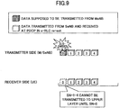
- the transmitting side in the RLC layer discards all of to-be-transmitted RLC PDUs (Packet Data Units) while the receiving side in the RLC layer re-assembles as many RLC SDUs (Service Data Units) as possible from the received RLC PDUs and delivers the re-assembled RLC SDUs to the PDCP layer. Also, various timers for use in the RLC layer are stopped and reset, and all various variables are initialized.
- RLC PDUs Packet Data Units
- RLC SDUs Service Data Units
- the transmitting side in the PDCP layer retransmits PDCP PDUs, whose acknowledgement (ACK) has not been received at the RLC layer, while the receiving side in the PDCP layer reorders RLC SDUs received with the re-establishment of the RLC layer and RLC SDUs newly transmitted after execution of the re-establishment.
- the PDCP layer performs different control operations with a reception window for reordering on the RLC SDUs received with the re-establishment of the RLC layer and the newly transmitted RLC SDUs.
- the PDCP layer does not update the reception window for the RLC SDUs received with the re-establishment in the RLC layer if PDCP sequence numbers of the received packets are out of sequence, but the PDCP layer updates the reception window for the newly transmitted RLC SDUs even if the PDCP sequence numbers of the received packets are out of sequence.
- Document CN 103 888 222 A discloses a method and an apparatus for processing a data packet so as to address the problem of how to process a PDCP SDU data packet for a split bearer in the scenario of bearer splitting while the split bearer is being transmitted normally, and when there is a change in secondary base stations serving the split bearer, to thereby improve the operating efficiency of the aggregated base stations, and the utilization ratio of resources.
- uplink communication from the user equipment is conducted by switching between two transmission directions, transmission to the master base station and transmission to the secondary base station, by RRC signaling.
- the re-establishment is not presently performed on the PDCP layer and the RLC layer.
- PDCP PDUs #0 to #3 distributed for transmission to the secondary base station in the uplink communication are still transmitted to the secondary base station even after changing the uplink transmission direction from the secondary base station to the master base station.
- the secondary base station may stop reception from the user equipment, and RLC PDUs #0 to #3 generated from the PDCP PDUs #0 to #3 would be unnecessarily transmitted.
- an object of the present invention is to provide some techniques for implementing efficient transmission of uplink packets when the uplink transmission direction is changed in the split bearer.
- user equipment and base stations supporting dual connectivity are disclosed.
- the user equipment performs re-establishment on an s-RLC layer, and the s-RLC layer assembles as many RLC SDUs as possible without discarding RLC PDUs waiting for reordering and transmits them to a PDCP layer.
- the user equipment performs re-establishment on the PDCP layer, and even if out-of-sequence in RLC SDUs (PDCP PDUs) received before expiration of a reordering timer is not eliminated, the PDCP layer uses the reordering timer to transmit the PDCP PDUs waiting for reordering to an upper layer.
- the PDCP layer uses the reordering timer to transmit the PDCP PDUs waiting for reordering to an upper layer.
- the user equipment when the transmission direction of uplink data packets is changed in uplink communication in the split bearer, the user equipment performs the re-establishment on the RLC layer and the PDCP layer. As a result, the user equipment can stop transmitting data packets distributed to a pre-changed transmission direction and transmit untransmitted data packets to a post-changed base station in sequence.
- FIG. 6 is a schematic diagram for illustrating a radio communication system according to one embodiment of the present invention.
- a radio communication system 10 has user equipment 100 and base stations 200A, 200B.
- the radio communication system 10 supports dual connectivity where the user equipment 100 uses component carriers CC#1, CC#2 served from the multiple base stations 200A, 200B to conduct simultaneous communication, and as illustrated, the user equipment 100 uses a dual connectivity function to communicate with the master base station (MeNB) 200A and the secondary base station (SeNB) 200B.
- MeNB master base station
- SeNB secondary base station
- only the two base stations 200A, 200B are illustrated, but a large number of base stations 200 are generally disposed to cover a service area of the radio communication system 10.
- the user equipment 100 has the dual connectivity function to communicate with the multiple base stations 200A, 200B simultaneously.
- the user equipment 100 may be any appropriate information processing device with a radio communication function such as a smartphone, a mobile phone, a tablet and a mobile router.
- the user equipment 100 is arranged with a CPU (Central Processing Unit) such as a processor, a memory device such as a RAM (Random Access Memory) and a flash memory, a radio communication device for transmitting and receiving radio signals to/from the base stations 200A, 200B and so on.
- a CPU Central Processing Unit
- a memory device such as a RAM (Random Access Memory) and a flash memory
- a radio communication device for transmitting and receiving radio signals to/from the base stations 200A, 200B and so on.
- functions and operations of the user equipment 100 as stated below may be implemented by the CPU processing and running data and programs stored in the memory device.
- the user equipment 100 is not limited to the above-stated hardware configuration and may be arranged with circuits for implementing
- the base stations 200A, 200B (which may be collectively referred to as the base stations 200 hereinafter) establish a radio connection to the user equipment 100 to transmit downlink (DL) packets received from network devices, such as an upper station and a server, communicatively connected on a core network (not shown) to the user equipment 100 as well as transmit uplink (UL) packets received from the user equipment 100 to the network devices.
- the base station 200A serves as a master base station (MeNB) or a primary base station
- the base station 200B serves as a secondary base station (SeNB).
- the master base station 200A controls simultaneous communication between the user equipment 100 and the base stations 200A, 200B in accordance with the dual connectivity and controls communication with the upper core network (not shown).
- the base station 200 is typically arranged with hardware resources such as an antenna for transmitting and receiving radio signals to/from the user equipment 100, a communication interface for communicating with an adjacent base station 200, a processor and a circuit for processing signals transmitted and received to/from the user equipment 100 and the adjacent base station 200. Functions and operations of the base station 200 as stated below may be implemented by the processor processing and running data and programs stored in the memory device.
- the base station 200 is not limited to the above-stated hardware configuration and may have any other appropriate hardware configuration.
- FIG. 7 is a block diagram for illustrating an arrangement of the user equipment according to one embodiment of the present invention.
- the user equipment 100 has a transmission and reception unit 110, an RLC layer processing unit 120 and a PDCP layer processing unit 130.
- the transmission and reception unit 110 communicates with the master base station 200A and the secondary base station 200B simultaneously in dual connectivity. Specifically, the transmission and reception unit 110 transmits and receives various radio channels, such as uplink/downlink control channels and uplink/downlink data channels, to/from the master base station 200A and the secondary base station 200B.
- various radio channels such as uplink/downlink control channels and uplink/downlink data channels
- the RLC layer processing unit 120 has an RLC (m-RLC) layer 121 for the master base station 200A and an RLC (s-RLC) layer for the secondary base station 200B.
- the m-RLC layer 121 assembles RLC SDUs from RLC PDUs received from the master base station 200A and transmits them to the PDCP layer processing unit 130.
- the s-RLC layer 122 assembles RLC SDUs from packets (RLC PDUs) received from the secondary base station 200B and transmits them to the PDCP layer processing unit 130.
- the m-RLC layer 121 assembles RLC PDUs from PDCP PDUs received from the PDCP layer processing unit 130 and transmits them to the master base station 200A via a lower layer (not shown).
- the s-RLC layer 122 assembles RLC PDUs from packets PDCP PDUs received from the PDCP layer processing unit 130 and transmits them to the secondary base station 200B via the lower layer (not shown).
- the PDCP layer processing unit 130 has a PDCP layer 131 transmitting and receiving data to/from the m-RLC layer 121 for the master base station 200A and the s-RLC layer 122 for the secondary base station 200B.
- the PDCP layer 131 receives RLC SDUs from the m-RLC layer 121 and the s-RLC layer 122, reorders the received packets based on sequence numbers (SNs) of the respective packets and transmits the reordered packets to an upper layer (not shown). In the reordering, the PDCP layer processing unit 130 uses a reception window.
- the PDCP layer processing unit 130 For packets received from the RLC layers with re-establishment, if the sequence numbers are out of sequence, the PDCP layer processing unit 130 does not update the reception window. For packets newly transmitted rather than with the re-establishment, on the other hand, even if the sequence numbers are out of sequence, the PDCP layer processing unit 130 determines that the packets have been discarded at the base station 200A or 200B serving as the transmitting side and updates the reception window.
- the PDCP layer 131 distributes to-be-transmitted PDCP PDUs into packets to be transmitted to the master base station 200A and packets to be transmitted to the secondary base station 200B and transmits the distributed packets to the m-RLC layer 121 and the s-RLC layer 122.
- split bearer deletion according to the first embodiment of the present invention is described with reference to FIGS. 8-12 .
- all packets waiting for reordering at the s-RLC layer 122 are discarded before deletion, and after the split bearer for the secondary base station 200B is deleted, the master base station 200A must retransmit the discarded packets.
- the first embodiment of the present invention as illustrated in FIG.
- the RLC layer processing unit 120 assembles as many RLC SDUs as possible from the packets (RLC-PUDs) waiting for reordering at the s-RLC layer 122 and transmits the RLC SDUs to the PDCP layer processing unit 130.
- the master base station 200A has to retransmit only the packets waiting for reception, which can avoid reduction in throughput.
- the RLC layer processing unit 120 when the split bearer configured for the secondary base station 200B is deleted, the RLC layer processing unit 120 performs re-establishment on the s-RLC layer 122 for the secondary base station 200B and releases the split bearer after execution of the re-establishment.
- the RLC layer processing unit 120 upon receiving a split bearer deletion command from the master base station 200A or the secondary base station 200B, the RLC layer processing unit 120 performs re-establishment on the s-RLC layer 122 configured for a secondary cell group (SCG) and then releases the split bearer.
- SCG secondary cell group
- the RLC layer processing unit 120 may transmit data packets staying in the s-RLC layer 122 for the secondary base station 200B or the SCG to the PDCP layer processing unit 130 in the re-establishment.
- the staying data packets are RLC PDUs waiting for reordering at the s-RLC layer 122 for the secondary base station 200B or the SCG, and the RLC layer processing unit 120 may assemble RLC SDUs from the RLC PDUs waiting for reordering and transmit the RLC SUDs to the PDCP layer processing unit 130.
- the RLC layer processing unit 120 When the RLC SDUs are assembled from the RLC PDUs waiting for reordering, similar to re-establishment in handover or reconnection, the RLC layer processing unit 120 re-assembles as many RLC SDUs as possible from the RLC PDUs waiting for reordering and delivers the re-assembled RLC SDUs to the PDCP layer processing unit 130.
- the RLC layer processing unit 120 may delete the indicated EPS bearer without execution of re-establishment for the s-RLC layer 122 for the secondary base station 200B or the SCG.
- the RLC layer processing unit 120 may not perform re-establishment on the s-RLC layer 122 for the secondary base station 200B or the SCG to re-assemble RLC SDUs from RLC PDUs waiting for reordering and transmit the RLC SDUs to the PDCP layer processing unit 130.
- the RLC layer processing unit 120 performs the re-establishment on the s-RLC layer 122 and re-assembles as many RLC SDUs as possible from the RLC PDUs without discarding the RLC PDUs waiting for reordering.
- the conventional PDCP layer changes operations for the received PDCP PDUs depending on operations at an lower layer and performs different operations, for example, handling missing packets as packets waiting for reordering or discarding the missing packets.
- the re-establishment is performed on the s-RLC layer 122, when the reordering is performed similar to the conventional one, unnecessary waiting for reordering would arise.
- the PDCP layer processing unit 130 waits for reception of RLC SDU #0 retransmitted from the master base station 200A for reordering. If the master base station 200A discards the RLC SDU #0, the PDCP layer processing unit 130 cannot receive the RLC SDU #0 and accordingly deliver the RLC SDUs #1 to #4 waiting for reordering to an upper layer. Accordingly, it is undesirable from standpoints of performance that in the case where the re-establishment is performed on the s-RLC layer 122, the PDCP layer processing unit 130 performs the reordering similar to the conventional manner.
- the PDCP layer processing unit 130 has a reordering timer activated in response to detecting that data packets are out of sequence, and uses the reordering timer to control reordering of packets received from the RLC layer processing unit 120 regardless of whether the re-establishment has been performed on the s-RLC layer 122. Specifically, upon expiration of the reordering timer, the PDCP layer processing unit 130 transmits data packets, which are waiting for reordering and are received from the RLC layer processing unit 120, to an upper layer. For example, as illustrated in FIG.
- the PDCP layer processing unit 130 if the PDCP layer processing unit 130 receives RLC SDUs #1 to #4 from the s-RLC layer 122, the PDCP layer processing unit 130 detects that RLC SDU #0 is missing and activates the reordering timer. If the PDCP layer processing unit 130 has failed to receive the RLC SDU #0 by expiration of the reordering timer, the PDCP layer processing unit 130 delivers the RLC SDUs #1 to #4 waiting for reordering to an upper layer. As a result, even in the case where the master base station 200A has discarded the RLC SDU #0, upon expiration of the reordering timer, the PDCP layer processing unit 130 can deliver the RLC SDUs #1 to #4 to the upper layer.
- the PDCP layer processing unit 130 may determine whether data packets waiting for reordering and received from the RLC layer processing unit 120 have been transmitted in connection with re-establishment on the m-RLC layer 121 for the master base station 200A and control the reordering timer depending on the determination.
- the PDCP layer processing unit 130 transmits the data packets waiting for reordering and received from the RLC layer processing unit 120 to an upper layer.
- the PDCP layer processing unit 130 performs reordering for handover or reconnection. Specifically, the PDCP layer processing unit 130 uses a reception window to reorder data packets received with the re-establishment and data packets newly transmitted after deletion of the split bearer. If there is a missing one in the data packets received with the re-establishment, the PDCP layer processing unit 130 does not update the reception window, and if there is a missing one in the newly transmitted data packets, the PDCP layer processing unit 130 updates the reception window.
- the PDCP layer processing unit 130 If the PDCP layer processing unit 130 receives the data packet falling in the reception window, the PDCP layer processing unit 130 updates the reception window with the sequence number of the received data packet, and if the PDCP layer processing unit 130 receives the data packet being out of the reception window, the PDCP layer processing unit 130 discards the data packet. In this manner, even if the RLC SDUs waiting for reception from the master base station 200A have been discarded, the PDCP layer processing unit 130 can use the reordering timer to deliver the RLC SDUs received with the re-establishment on the s-RLC layer 122 to an upper layer.
- FIG. 11 is a flowchart for illustrating split bearer deletion at the RLC layer processing unit according to the first embodiment of the present invention.
- the master base station 200A configures split bearer for the user equipment 100.
- the split bearer configuration command may be indicated by RRC signaling, for example.
- the master base station 200A indicates the user equipment 100 to delete the split bearer.
- the split bearer deletion command may be indicated by RRC signaling, for example.
- the RLC layer processing unit 120 performs re-establishment on the s-RLC layer 122. Specifically, the RLC layer processing unit 120 assembles as many RLC SDUs as possible from RLC PDUs waiting for reordering at the s-RLC layer 122 and delivers them to the PDCP layer processing unit 130.
- the RLC layer processing unit 120 releases the s-RLC layer 122.
- FIG. 12 is a flowchart for illustrating split bearer deletion at the PDCP layer processing unit according to the first embodiment of the present invention.
- the master base station 200A configures split bearer for the user equipment 100.
- the split bearer configuration command may be indicated by RRC signaling, for example.
- the PDCP layer processing unit 130 receives RLC SDUs assembled from RLC PDUs waiting for reordering from the RLC layer processing unit 120.
- the PDCP layer processing unit 130 determines whether the received RLC SDUs have been transmitted in connection with re-establishment on the m-RLC layer 121. If the received RLC SDUs have been transmitted in connection with re-establishment on the m-RLC layer 121 (S203: Yes), at step S204, the PDCP layer processing unit 130 performs reordering for handover or reconnection.
- the PDCP layer processing unit 130 performs reordering for the split bearer. Specifically, if the sequence numbers of the received RLC SDUs are out of sequence, the PDCP layer processing unit 130 activates the reordering timer. Then, if a missing one of the RLC SDUs has not been received by expiration of the reordering timer, the PDCP layer processing unit 130 assembles PDCP SDUs from the RLC SDUs (PDCP PDUs) waiting for reordering and delivers them to an upper layer.
- PDCP PDUs PDCP PDUs
- uplink transmission direction change operations in split bearers according to the second embodiment of the present invention are described with reference to FIGS. 13-14 .
- data packets RLC PDUs #0 to #3 in the s-RLC layer 122 in the example illustrated in FIG. 5
- a pre-changed base station 200 the secondary base station 200B in the example illustrated in FIG. 5
- the RLC layer processing unit 120 and the PDCP layer processing unit 130 perform re-establishment on the RLC layer and the PDCP layer, respectively.
- the user equipment 100 can stop transmitting the data packets distributed in the pre-changed transmission direction and transmitting the untransmitted data packets in the post-changed base station 200 in sequence.
- the RLC layer processing unit 120 when the transmission direction of uplink data packets is changed in the split bearers configured for the master base station 200A and the secondary base station 200B, the RLC layer processing unit 120 performs re-establishment on the m-RLC layer 121 for the master base station 200A and the s-RLC layer 122 for the secondary base station 200B, and the PDCP layer processing unit 130 performs the re-establishment on the PDCP layer 131.
- the RLC layer processing unit 120 upon receiving an uplink transmission direction change command from the master base station 200A or the secondary base station 200B, performs the re-establishment on the m-RLC layer 121 and the s-RLC layer 122, and the PDCP layer processing unit 130 performs the re-establishment on the PDCP layer 131.
- the transmission direction change of uplink data packets may be triggered with handover between master base stations, for example.
- the user equipment 100 receives a handover command (HO command) including a dual connectivity deletion command and changes the transmission direction of uplink data packets from the secondary base station 200B to the master base station 200A in accordance with the dual connectivity deletion command.
- HO command handover command
- the RLC layer processing unit 120 When the transmission direction of uplink data packets is changed from the secondary base station 200B to the master base station 200A, the RLC layer processing unit 120 performs re-establishment on the m-RLC layer 121 and the s-RLC layer 122, and the PDCP layer processing unit 130 performs re-establishment on the PDCP layer 131.
- the RLC layer processing unit 120 may perform the re-establishment on the m-RLC layer 121 for the master base station 200A and the s-RLC layer 122 for the secondary base station 200B, and the PDCP layer processing unit 130 may perform the re-establishment on the PDCP layer 131.
- the RLC layer processing unit 120 and the PDCP layer processing unit 130 may perform the re-establishment on the RLC layers 121, 122 and the PDCP layer 131 to stop transmitting uplink data packets distributed before changing the transmission direction and transmit the transmission-stopped uplink data packets to a base station in a post-changed transmission direction.
- the RLC layer processing unit 120 and the PDCP layer processing unit 130 may perform the re-establishment on the RLC layers 121, 122 and the PDCP layer 131 to transmit the transmission-stopped uplink data packets in sequence of the sequence numbers.
- the untransmitted uplink data packets can be transmitted to the post-changed base station 200 in sequence, and data packets having earlier sequence numbers arrive at the post-changed base station 200 before, which can avoid a likelihood that data packets having later sequence numbers may be discarded as being out of a reception window.
- the RLC layer processing unit 120 and the PDCP layer processing unit 130 may perform the re-establishment. Specifically, there are some cases where the base station 200 continues receiving data packets even after changing the transmission direction and the re-establishment is unnecessary. Accordingly, in the case where the base station 200 for the pre-changed transmission direction can receive data packets even after changing the transmission direction, the base station 200 may indicate to the user equipment 100 whether the re-establishment is necessary.
- the RLC layer processing unit 120 and the PDCP layer processing unit 130 may the re-establishment and may not perform the re-establishment in the other cases.
- the RLC layer processing unit 120 and the PDCP layer processing unit 130 may not perform the re-establishment and in the other cases, may perform the re-establishment. According to this embodiment, it is possible to avoid unnecessary re-establishment.
- the re-establishment may be performed on only uplink communication.
- the RLC layer processing unit 120 and the PDCP layer processing unit 130 may perform the re-establishment on only an uplink communication related portion for the RLC layers 121, 122 and the PDCP layer 131. If the re-establishment is also performed on a downlink communication related portion, the downlink communication is temporarily interrupted, which can be avoided.
- the user equipment 100 may perform the re-establishment on only portions related to the transmitting side in the RLC layer and the PDCP layer
- the base station 200 may perform the re-establishment on only portions related to the receiving side in the RLC layer and the PDCP layer.
- FIG. 13 is a flowchart for illustrating an uplink transmission direction change operation in the user equipment according to the second embodiment of the present invention.
- the user equipment 100 configures a split bearer for the non-anchor base station 200.
- the split bearer configuration command may be indicated by RRC signaling, for example.
- the user equipment 100 receives an uplink transmission direction change command.
- the uplink transmission direction change command may be indicated by RRC signaling, for example.
- the uplink transmission direction change may be triggered with reception of a handover (HO) command including a dual connectivity deletion command indicated in response to activation of a handover procedure between master base stations (inter-MeNB HO).
- HO handover
- the RLC layer processing unit 120 and the PDCP layer processing unit 130 perform re-establishment on the m-RLC layer 121 and the s-RLC layer 122 and the PDCP layer 131, respectively.
- the RLC layer processing unit 120 and the PDCP layer processing unit 130 may perform the re-establishment on the RLC layers 121, 122 and the PDCP layer 131 to stop transmitting uplink data packets distributed before changing the transmission direction and transmit the transmission-stopped uplink data packets to the base station 200 for the post-changed transmission direction in the order of the sequence numbers.
- FIG. 14 is a block diagram for illustrating an arrangement of the base station according to the second embodiment of the present invention.
- the base station according to this embodiment has an uplink reordering timer in the PDCP layer and upon changing the uplink transmission direction in the split bearer, activates the uplink reordering timer and suspends delivering data packets received from the user equipment 100 to an upper layer before the sequence number becomes in sequence during activation of the uplink reordering timer.
- the base station 200 has a transmission and reception unit 210, an RLC layer processing unit 220 and a PDCP layer processing unit 230.
- the transmission and reception unit 210 communicates with the user equipment 100 in dual connectivity. Specifically, the transmission and reception unit 210 transmits and receives various radio channels, such as uplink/downlink control channels and uplink/downlink data channels, to/from the user equipment 100.
- various radio channels such as uplink/downlink control channels and uplink/downlink data channels
- the RLC layer processing unit 220 has an RLC layer 221 to communicate with the user equipment 100.
- the RLC layer processing unit 220 assembles RLC SDUs from RLC PDUs received from the user equipment 100 via a lower layer and if the base station 200 serves as an anchor node in the split bearer, transmits the assembled RLC SDUs to its own PDCP layer processing unit 230.
- the base station 200 transmits the assembled RLC SDUs to the PDCP layer processing unit 230 in the anchor base station 200.
- the PDCP layer processing unit 230 has a PDCP layer 231 to communicate with the user equipment 100.
- the PDCP layer processing unit 230 reorders RLC SDUs received from its own RLC layer processing unit 220 and RLC SDUs received from the RLC layer processing unit 220 in a different base station 200, for which the split bearer is configured, to assemble PDCP SDUs and transmit them to an upper layer.
- the PDCP layer processing unit 230 has an uplink reordering timer and when the transmission direction of uplink data packets is changed in the split bearer configured for the user equipment 100, activates the uplink reordering timer. If the sequence numbers of the uplink data packets received from the user equipment 100 is out of sequence, the PDCP layer processing unit 230 suspends transmitting the received uplink data packets to an upper layer.
- the PDCP layer processing unit 230 may transmit the received uplink data packets to the upper layer. Specifically, if the PDCP layer processing unit 230 has failed to receive a missing one of the uplink data packets from the user equipment 100 before expiration of the uplink reordering timer, the PDCP layer processing unit 230 abandons reception of the missing uplink data packet and transmits the uplink data packets waiting for reordering to the upper layer.
- the PDCP layer processing unit 230 stops the uplink reordering timer and transmits the received uplink data packet to the upper layer. Specifically, if the missing uplink data packet is received from the user equipment 100 before expiration of the uplink reordering timer, the PDCP layer processing unit 230 reorders the received uplink data packet and the uplink data packets waiting for reordering and transmits them to the upper layer.
- the former is always used for reordering while the latter is used only at a certain timing, that is, a timing of changing the uplink transmission direction.
- the PDCP layer processing unit 230 determines that the uplink data packet corresponding to the missing sequence number has been discarded in the user equipment 100.
- the above-stated first and second embodiments may be used separately or in combination.
- the first embodiment may be to downlink communication
- the second embodiment may be applied to uplink communication.
- the split bearer configured for the secondary base station 200B is deleted in the downlink communication
- the user equipment 100 performs re-establishment on the s-RLC layer 122 for the secondary base station 200B and releases the split bearer after execution of the re-establishment.
- the user equipment 100 may perform the re-establishment on the m-RLC layer 121 for the master base station 200A, the s-RLC layer 122 for the secondary base station 200B and the PDCP layer 131.
Landscapes
- Engineering & Computer Science (AREA)
- Computer Networks & Wireless Communication (AREA)
- Signal Processing (AREA)
- Quality & Reliability (AREA)
- Mobile Radio Communication Systems (AREA)
Claims (4)
- Équipement utilisateur comprenant :une unité de transmission et de réception (110) configurée pour communiquer avec une station de base maître (200A) et une station de base secondaire (200B) simultanément en double connectivité ;une unité de traitement de couche de commande de liaison radio, RLC, (120) configurée pour avoir une couche RLC pour la station de base maître (m-RLC) et une couche RLC pour la station de base secondaire (s-RLC) ; etune unité de traitement de couche de protocole de convergence de données par paquets, PDCP, configurée pour avoir une couche PDCP transmettant et recevant des données vers/à partir de la couche RLC pour la station de base maître (m-RLC) et la couche RLC pour la station de base secondaire (s-RLC),dans lequel, quand une direction de transmission de paquets de données de liaison montante est changée de la station de base secondaire à la station de base maître dans un support divisé configuré pour la station de base maître (200A) et la station de base secondaire (200B), l'unité de traitement de couche RLC (120) effectue un ré-établissement sur la couche RLC pour la station de base maître (200A) et la couche RLC pour la station de base secondaire (200B), et l'unité de traitement de couche PDCP (130) effectue un ré-établissement sur la couche PDCP, pour arrêter la transmission de paquets de données de liaison montante distribués avant le changement de la direction de transmission et transmettre des paquets de données de liaison montante non transmis à la station de base maître.
- Équipement utilisateur selon la revendication 1, dans lequel l'unité de traitement de couche RLC (120) et l'unité de traitement de couche PDCP (130) effectuent le ré-établissement sur les couches RLC et la couche PDCP pour transmettre les paquets de données de liaison montante non transmis dans une séquence de nombres séquentiels.
- Équipement utilisateur selon l'une quelconque des revendications 1 à 2, dans lequel, quand une commande de ré-établissement est reçue à partir de la station de base secondaire, l'unité de traitement de couche RLC (120) et l'unité de traitement de couche PDCP (130) effectuent le ré-établissement.
- Équipement utilisateur selon l'une quelconque des revendications 1 à 3, dans lequel le ré-établissement est effectué sur une communication de liaison montante seulement.
Applications Claiming Priority (2)
| Application Number | Priority Date | Filing Date | Title |
|---|---|---|---|
| JP2014160762 | 2014-08-06 | ||
| PCT/JP2015/072282 WO2016021662A1 (fr) | 2014-08-06 | 2015-08-05 | Équipement d'utilisateur, et station de base |
Publications (3)
| Publication Number | Publication Date |
|---|---|
| EP3179770A1 EP3179770A1 (fr) | 2017-06-14 |
| EP3179770A4 EP3179770A4 (fr) | 2017-11-22 |
| EP3179770B1 true EP3179770B1 (fr) | 2020-01-01 |
Family
ID=55263920
Family Applications (1)
| Application Number | Title | Priority Date | Filing Date |
|---|---|---|---|
| EP15830364.4A Active EP3179770B1 (fr) | 2014-08-06 | 2015-08-05 | Équipement d'utilisateur |
Country Status (7)
| Country | Link |
|---|---|
| US (1) | US10306699B2 (fr) |
| EP (1) | EP3179770B1 (fr) |
| JP (1) | JP6078699B2 (fr) |
| CN (1) | CN106031229B (fr) |
| BR (1) | BR112016016595B1 (fr) |
| HU (1) | HUE047983T2 (fr) |
| WO (1) | WO2016021662A1 (fr) |
Families Citing this family (21)
| Publication number | Priority date | Publication date | Assignee | Title |
|---|---|---|---|---|
| CN102833802B (zh) * | 2012-08-15 | 2015-09-23 | 电信科学技术研究院 | 一种数据转发方法及设备 |
| WO2016019584A1 (fr) * | 2014-08-08 | 2016-02-11 | 华为技术有限公司 | Procédé de traitement de support radio, équipement utilisateur et station de base |
| CN107094299B (zh) * | 2016-02-18 | 2021-03-12 | 中国移动通信集团公司 | 自适应于接入网架构的数据处理方法及接入网架构 |
| EP3420695B1 (fr) * | 2016-02-23 | 2020-04-08 | Telefonaktiebolaget LM Ericsson (PUBL) | Procédés utilisés dans des équipements d'utilisateur et les ue associés |
| WO2017177223A1 (fr) * | 2016-04-08 | 2017-10-12 | Altiostar Networks, Inc. | Connectivité double |
| CN107333298B (zh) * | 2016-04-29 | 2020-03-24 | 电信科学技术研究院 | 一种数据传输方法及相关设备 |
| WO2018116096A1 (fr) | 2016-12-19 | 2018-06-28 | Netsia, Inc. | Système et procédé de virtualisation programmable de réseaux hétérogènes à canaux communs utilisant une application associée à une connectivité double |
| EP3556176B1 (fr) | 2016-12-19 | 2023-03-22 | Netsia, Inc. | Procédé de virtualisation et d'équilibrage de charge programmables de réseaux hétérogènes à canaux divisés utilisant une connectivité double |
| US11102670B2 (en) * | 2017-03-23 | 2021-08-24 | Lg Electronics Inc. | Method for transmitting lossless data packet based on quality of service (qos) framework in wireless communication system and a device therefor |
| US10237784B2 (en) | 2017-03-24 | 2019-03-19 | Motorola Mobility Llc | Split bearer packet data converge protocol protocol data unit routing |
| EP4142195A1 (fr) * | 2017-06-02 | 2023-03-01 | Motorola Mobility LLC | Détermination de données disponibles pour une transmission |
| EP3720229B1 (fr) * | 2017-06-15 | 2022-08-31 | Guangdong Oppo Mobile Telecommunications Corp., Ltd. | Procédé de planification de ressources et appareil pour un canal logique |
| WO2018227501A1 (fr) | 2017-06-15 | 2018-12-20 | Oppo广东移动通信有限公司 | Procédé et dispositif de transmission de données |
| CN110383880B (zh) * | 2017-08-11 | 2022-12-23 | Lg电子株式会社 | 用于发送数据单元的方法和设备 |
| CN110999519B (zh) | 2017-08-11 | 2023-10-27 | 三星电子株式会社 | 对为用户设备配置的多个承载执行承载类型改变的方法 |
| EP3669578B1 (fr) | 2017-09-28 | 2022-07-13 | Samsung Electronics Co., Ltd. | Procédé et système de gestion d'une opération pdcp dans un système de communication sans fil |
| CN111434183B (zh) * | 2017-09-29 | 2024-03-12 | 三星电子株式会社 | 无线通信系统中以双连接处理用户平面的方法和用户设备 |
| WO2019093828A1 (fr) * | 2017-11-10 | 2019-05-16 | Samsung Electronics Co., Ltd. | Procédé et appareil de transmission et de réception de données dans un système de communication sans fil |
| WO2019153281A1 (fr) * | 2018-02-09 | 2019-08-15 | Oppo广东移动通信有限公司 | Procédé de configuration pour entité pdcp et dispositif associé |
| WO2020087368A1 (fr) * | 2018-10-31 | 2020-05-07 | Mediatek Singapore Pte. Ltd. | Appareil et mécanisme de ré-ordonnancement à double protocole pour réduire une interruption de mobilité dans un réseau sans fil |
| KR20210152853A (ko) * | 2020-06-09 | 2021-12-16 | 삼성전자주식회사 | 이중접속 네트워크에서 패킷을 재전송하는 방법 및 장치 |
Citations (1)
| Publication number | Priority date | Publication date | Assignee | Title |
|---|---|---|---|---|
| WO2015171053A1 (fr) * | 2014-05-09 | 2015-11-12 | Telefonaktiebolaget L M Ericsson (Publ) | Reconfiguration de liaison montante pour un support divisé dans une connectivité double |
Family Cites Families (11)
| Publication number | Priority date | Publication date | Assignee | Title |
|---|---|---|---|---|
| CN102271373B (zh) * | 2011-08-30 | 2017-09-15 | 中兴通讯股份有限公司 | X2切换方法及装置 |
| WO2013155709A1 (fr) * | 2012-04-20 | 2013-10-24 | 华为技术有限公司 | Procédé de configuration pour diffusion de données en flux, système de station de base et équipement d'utilisateur |
| CN103596213B (zh) * | 2012-08-17 | 2017-03-29 | 电信科学技术研究院 | 异构网络下的层二测量及信息交互方法和设备 |
| US9572171B2 (en) * | 2013-10-31 | 2017-02-14 | Intel IP Corporation | Systems, methods, and devices for efficient device-to-device channel contention |
| CN105850204A (zh) * | 2013-11-01 | 2016-08-10 | 诺基亚技术有限公司 | 用于在具有双连接的情况下处理缓冲器状态报告和调度请求的方法和装置 |
| JPWO2015115629A1 (ja) * | 2014-01-31 | 2017-03-23 | 京セラ株式会社 | 通信制御方法、マスタ基地局、及びセカンダリ基地局 |
| CN104837163B (zh) * | 2014-02-08 | 2019-10-25 | 夏普株式会社 | 用于删除无线链路控制服务数据单元的方法和基站 |
| KR102068948B1 (ko) * | 2014-03-10 | 2020-01-21 | 닛본 덴끼 가부시끼가이샤 | Dc (이중 접속성) 를 위한 장치, 시스템 및 방법 |
| WO2015141478A1 (fr) * | 2014-03-19 | 2015-09-24 | 株式会社Nttドコモ | Dispositif utilisateur et procédé de transmission de données de liaison montante |
| CN108306708B (zh) * | 2014-03-21 | 2020-07-10 | 电信科学技术研究院 | 一种数据包处理方法及装置 |
| US9838282B2 (en) * | 2014-05-09 | 2017-12-05 | Telefonaktiebolaget Lm Ericsson (Publ) | PDCP and flow control for split bearer |
-
2015
- 2015-08-05 EP EP15830364.4A patent/EP3179770B1/fr active Active
- 2015-08-05 JP JP2016540275A patent/JP6078699B2/ja active Active
- 2015-08-05 HU HUE15830364A patent/HUE047983T2/hu unknown
- 2015-08-05 BR BR112016016595-0A patent/BR112016016595B1/pt active IP Right Grant
- 2015-08-05 US US15/116,855 patent/US10306699B2/en active Active
- 2015-08-05 CN CN201580008705.0A patent/CN106031229B/zh active Active
- 2015-08-05 WO PCT/JP2015/072282 patent/WO2016021662A1/fr active Application Filing
Patent Citations (1)
| Publication number | Priority date | Publication date | Assignee | Title |
|---|---|---|---|---|
| WO2015171053A1 (fr) * | 2014-05-09 | 2015-11-12 | Telefonaktiebolaget L M Ericsson (Publ) | Reconfiguration de liaison montante pour un support divisé dans une connectivité double |
Non-Patent Citations (2)
| Title |
|---|
| NSN ET AL: "Handover procedure in case of bearer only served by SeNB (1A)", vol. RAN WG3, no. San Francisco, USA; 20131111 - 20131115, 13 November 2013 (2013-11-13), XP050738361, Retrieved from the Internet <URL:http://www.3gpp.org/ftp/Meetings_3GPP_SYNC/RAN/RAN3/Docs/> [retrieved on 20131113] * |
| NSN ET AL: "Handover procedure in case of bearer served by MeNB and SeNB (3C)", vol. RAN WG3, no. San Francisco, USA; 20131111 - 20131115, 13 November 2013 (2013-11-13), XP050738362, Retrieved from the Internet <URL:http://www.3gpp.org/ftp/Meetings_3GPP_SYNC/RAN/RAN3/Docs/> [retrieved on 20131113] * |
Also Published As
| Publication number | Publication date |
|---|---|
| BR112016016595A2 (fr) | 2017-08-08 |
| CN106031229A (zh) | 2016-10-12 |
| EP3179770A4 (fr) | 2017-11-22 |
| US10306699B2 (en) | 2019-05-28 |
| JP6078699B2 (ja) | 2017-02-08 |
| JPWO2016021662A1 (ja) | 2017-04-27 |
| BR112016016595B1 (pt) | 2023-10-17 |
| US20170171905A1 (en) | 2017-06-15 |
| CN106031229B (zh) | 2019-12-13 |
| HUE047983T2 (hu) | 2020-05-28 |
| WO2016021662A1 (fr) | 2016-02-11 |
| EP3179770A1 (fr) | 2017-06-14 |
Similar Documents
| Publication | Publication Date | Title |
|---|---|---|
| EP3179770B1 (fr) | Équipement d'utilisateur | |
| EP3179819B1 (fr) | Équipement utilisateur pour connectivité double | |
| US10314030B2 (en) | Method and apparatus for transmitting and receiving data using plurality of carriers in mobile communication system | |
| KR102460350B1 (ko) | 통신 시스템에서 데이터 송수신 방법 및 장치 | |
| US20180213592A1 (en) | Method and apparatus for sequential forwarding considering multi-flow in dual connectivity system | |
| WO2020087368A1 (fr) | Appareil et mécanisme de ré-ordonnancement à double protocole pour réduire une interruption de mobilité dans un réseau sans fil | |
| US10039149B2 (en) | User equipment and uplink data transmission method | |
| US10425861B2 (en) | Method and apparatus for preventing loss of data packets | |
| WO2015021412A1 (fr) | Procédé et système destinés à des améliorations de couche de protocole dans le déchargement de données sur de petites cellules | |
| CN113396607A (zh) | 用于在无线通信系统中执行切换的方法和设备 | |
| CN116996950A (zh) | 用于移动性增强的双协议的方法及其用户设备 | |
| US20220201786A1 (en) | Methods and apparatus to reduce packet latency in multi-leg transmission | |
| KR20150126535A (ko) | 듀얼 커넥티비티 하에서 데이터 송수신 방법 및 그 장치 | |
| US20230156817A1 (en) | Handling of Uplink Listen-Before-Talk Failures for Handover | |
| JP6298745B2 (ja) | ユーザ装置及び基地局 | |
| KR20190085760A (ko) | 무선 통신 시스템에서 무선 링크 실패 처리 동작 방법 및 장치 | |
| CA3235117A1 (fr) | Procede de transmission de donnees et appareil de communication | |
| JP2019068459A (ja) | 基地局 |
Legal Events
| Date | Code | Title | Description |
|---|---|---|---|
| STAA | Information on the status of an ep patent application or granted ep patent |
Free format text: STATUS: THE INTERNATIONAL PUBLICATION HAS BEEN MADE |
|
| PUAI | Public reference made under article 153(3) epc to a published international application that has entered the european phase |
Free format text: ORIGINAL CODE: 0009012 |
|
| STAA | Information on the status of an ep patent application or granted ep patent |
Free format text: STATUS: REQUEST FOR EXAMINATION WAS MADE |
|
| 17P | Request for examination filed |
Effective date: 20160707 |
|
| AK | Designated contracting states |
Kind code of ref document: A1 Designated state(s): AL AT BE BG CH CY CZ DE DK EE ES FI FR GB GR HR HU IE IS IT LI LT LU LV MC MK MT NL NO PL PT RO RS SE SI SK SM TR |
|
| AX | Request for extension of the european patent |
Extension state: BA ME |
|
| RIC1 | Information provided on ipc code assigned before grant |
Ipc: H04W 16/32 20090101ALN20170706BHEP Ipc: H04W 76/02 20090101ALI20170706BHEP Ipc: H04W 28/10 20090101AFI20170706BHEP Ipc: H04W 76/04 20090101ALI20170706BHEP |
|
| DAV | Request for validation of the european patent (deleted) | ||
| DAX | Request for extension of the european patent (deleted) | ||
| A4 | Supplementary search report drawn up and despatched |
Effective date: 20171019 |
|
| RIC1 | Information provided on ipc code assigned before grant |
Ipc: H04W 28/10 20090101AFI20171013BHEP Ipc: H04W 16/32 20090101ALN20171013BHEP Ipc: H04W 76/02 20090101ALI20171013BHEP Ipc: H04W 76/04 20090101ALI20171013BHEP |
|
| STAA | Information on the status of an ep patent application or granted ep patent |
Free format text: STATUS: EXAMINATION IS IN PROGRESS |
|
| 17Q | First examination report despatched |
Effective date: 20180807 |
|
| GRAP | Despatch of communication of intention to grant a patent |
Free format text: ORIGINAL CODE: EPIDOSNIGR1 |
|
| STAA | Information on the status of an ep patent application or granted ep patent |
Free format text: STATUS: GRANT OF PATENT IS INTENDED |
|
| RIC1 | Information provided on ipc code assigned before grant |
Ipc: H04W 76/25 20180101ALI20190917BHEP Ipc: H04W 36/04 20090101ALN20190917BHEP Ipc: H04W 16/32 20090101ALN20190917BHEP Ipc: H04W 28/10 20090101AFI20190917BHEP Ipc: H04W 76/15 20180101ALI20190917BHEP |
|
| RIC1 | Information provided on ipc code assigned before grant |
Ipc: H04W 16/32 20090101ALN20190924BHEP Ipc: H04W 28/10 20090101AFI20190924BHEP Ipc: H04W 36/04 20090101ALN20190924BHEP Ipc: H04W 76/25 20180101ALI20190924BHEP Ipc: H04W 76/15 20180101ALI20190924BHEP |
|
| INTG | Intention to grant announced |
Effective date: 20191008 |
|
| GRAS | Grant fee paid |
Free format text: ORIGINAL CODE: EPIDOSNIGR3 |
|
| GRAA | (expected) grant |
Free format text: ORIGINAL CODE: 0009210 |
|
| STAA | Information on the status of an ep patent application or granted ep patent |
Free format text: STATUS: THE PATENT HAS BEEN GRANTED |
|
| AK | Designated contracting states |
Kind code of ref document: B1 Designated state(s): AL AT BE BG CH CY CZ DE DK EE ES FI FR GB GR HR HU IE IS IT LI LT LU LV MC MK MT NL NO PL PT RO RS SE SI SK SM TR |
|
| REG | Reference to a national code |
Ref country code: GB Ref legal event code: FG4D |
|
| REG | Reference to a national code |
Ref country code: CH Ref legal event code: EP Ref country code: AT Ref legal event code: REF Ref document number: 1221395 Country of ref document: AT Kind code of ref document: T Effective date: 20200115 |
|
| REG | Reference to a national code |
Ref country code: DE Ref legal event code: R096 Ref document number: 602015044853 Country of ref document: DE |
|
| REG | Reference to a national code |
Ref country code: IE Ref legal event code: FG4D |
|
| REG | Reference to a national code |
Ref country code: NL Ref legal event code: MP Effective date: 20200101 |
|
| REG | Reference to a national code |
Ref country code: HU Ref legal event code: AG4A Ref document number: E047983 Country of ref document: HU |
|
| REG | Reference to a national code |
Ref country code: LT Ref legal event code: MG4D |
|
| PG25 | Lapsed in a contracting state [announced via postgrant information from national office to epo] |
Ref country code: LT Free format text: LAPSE BECAUSE OF FAILURE TO SUBMIT A TRANSLATION OF THE DESCRIPTION OR TO PAY THE FEE WITHIN THE PRESCRIBED TIME-LIMIT Effective date: 20200101 Ref country code: RS Free format text: LAPSE BECAUSE OF FAILURE TO SUBMIT A TRANSLATION OF THE DESCRIPTION OR TO PAY THE FEE WITHIN THE PRESCRIBED TIME-LIMIT Effective date: 20200101 Ref country code: NL Free format text: LAPSE BECAUSE OF FAILURE TO SUBMIT A TRANSLATION OF THE DESCRIPTION OR TO PAY THE FEE WITHIN THE PRESCRIBED TIME-LIMIT Effective date: 20200101 Ref country code: CZ Free format text: LAPSE BECAUSE OF FAILURE TO SUBMIT A TRANSLATION OF THE DESCRIPTION OR TO PAY THE FEE WITHIN THE PRESCRIBED TIME-LIMIT Effective date: 20200101 Ref country code: PT Free format text: LAPSE BECAUSE OF FAILURE TO SUBMIT A TRANSLATION OF THE DESCRIPTION OR TO PAY THE FEE WITHIN THE PRESCRIBED TIME-LIMIT Effective date: 20200527 Ref country code: NO Free format text: LAPSE BECAUSE OF FAILURE TO SUBMIT A TRANSLATION OF THE DESCRIPTION OR TO PAY THE FEE WITHIN THE PRESCRIBED TIME-LIMIT Effective date: 20200401 Ref country code: FI Free format text: LAPSE BECAUSE OF FAILURE TO SUBMIT A TRANSLATION OF THE DESCRIPTION OR TO PAY THE FEE WITHIN THE PRESCRIBED TIME-LIMIT Effective date: 20200101 |
|
| PG25 | Lapsed in a contracting state [announced via postgrant information from national office to epo] |
Ref country code: SE Free format text: LAPSE BECAUSE OF FAILURE TO SUBMIT A TRANSLATION OF THE DESCRIPTION OR TO PAY THE FEE WITHIN THE PRESCRIBED TIME-LIMIT Effective date: 20200101 Ref country code: LV Free format text: LAPSE BECAUSE OF FAILURE TO SUBMIT A TRANSLATION OF THE DESCRIPTION OR TO PAY THE FEE WITHIN THE PRESCRIBED TIME-LIMIT Effective date: 20200101 Ref country code: HR Free format text: LAPSE BECAUSE OF FAILURE TO SUBMIT A TRANSLATION OF THE DESCRIPTION OR TO PAY THE FEE WITHIN THE PRESCRIBED TIME-LIMIT Effective date: 20200101 Ref country code: IS Free format text: LAPSE BECAUSE OF FAILURE TO SUBMIT A TRANSLATION OF THE DESCRIPTION OR TO PAY THE FEE WITHIN THE PRESCRIBED TIME-LIMIT Effective date: 20200501 Ref country code: GR Free format text: LAPSE BECAUSE OF FAILURE TO SUBMIT A TRANSLATION OF THE DESCRIPTION OR TO PAY THE FEE WITHIN THE PRESCRIBED TIME-LIMIT Effective date: 20200402 Ref country code: BG Free format text: LAPSE BECAUSE OF FAILURE TO SUBMIT A TRANSLATION OF THE DESCRIPTION OR TO PAY THE FEE WITHIN THE PRESCRIBED TIME-LIMIT Effective date: 20200401 |
|
| REG | Reference to a national code |
Ref country code: DE Ref legal event code: R097 Ref document number: 602015044853 Country of ref document: DE |
|
| PG25 | Lapsed in a contracting state [announced via postgrant information from national office to epo] |
Ref country code: RO Free format text: LAPSE BECAUSE OF FAILURE TO SUBMIT A TRANSLATION OF THE DESCRIPTION OR TO PAY THE FEE WITHIN THE PRESCRIBED TIME-LIMIT Effective date: 20200101 Ref country code: SM Free format text: LAPSE BECAUSE OF FAILURE TO SUBMIT A TRANSLATION OF THE DESCRIPTION OR TO PAY THE FEE WITHIN THE PRESCRIBED TIME-LIMIT Effective date: 20200101 Ref country code: EE Free format text: LAPSE BECAUSE OF FAILURE TO SUBMIT A TRANSLATION OF THE DESCRIPTION OR TO PAY THE FEE WITHIN THE PRESCRIBED TIME-LIMIT Effective date: 20200101 Ref country code: ES Free format text: LAPSE BECAUSE OF FAILURE TO SUBMIT A TRANSLATION OF THE DESCRIPTION OR TO PAY THE FEE WITHIN THE PRESCRIBED TIME-LIMIT Effective date: 20200101 Ref country code: DK Free format text: LAPSE BECAUSE OF FAILURE TO SUBMIT A TRANSLATION OF THE DESCRIPTION OR TO PAY THE FEE WITHIN THE PRESCRIBED TIME-LIMIT Effective date: 20200101 Ref country code: SK Free format text: LAPSE BECAUSE OF FAILURE TO SUBMIT A TRANSLATION OF THE DESCRIPTION OR TO PAY THE FEE WITHIN THE PRESCRIBED TIME-LIMIT Effective date: 20200101 |
|
| PLBE | No opposition filed within time limit |
Free format text: ORIGINAL CODE: 0009261 |
|
| STAA | Information on the status of an ep patent application or granted ep patent |
Free format text: STATUS: NO OPPOSITION FILED WITHIN TIME LIMIT |
|
| REG | Reference to a national code |
Ref country code: AT Ref legal event code: MK05 Ref document number: 1221395 Country of ref document: AT Kind code of ref document: T Effective date: 20200101 |
|
| 26N | No opposition filed |
Effective date: 20201002 |
|
| PG25 | Lapsed in a contracting state [announced via postgrant information from national office to epo] |
Ref country code: AT Free format text: LAPSE BECAUSE OF FAILURE TO SUBMIT A TRANSLATION OF THE DESCRIPTION OR TO PAY THE FEE WITHIN THE PRESCRIBED TIME-LIMIT Effective date: 20200101 |
|
| PG25 | Lapsed in a contracting state [announced via postgrant information from national office to epo] |
Ref country code: PL Free format text: LAPSE BECAUSE OF FAILURE TO SUBMIT A TRANSLATION OF THE DESCRIPTION OR TO PAY THE FEE WITHIN THE PRESCRIBED TIME-LIMIT Effective date: 20200101 Ref country code: SI Free format text: LAPSE BECAUSE OF FAILURE TO SUBMIT A TRANSLATION OF THE DESCRIPTION OR TO PAY THE FEE WITHIN THE PRESCRIBED TIME-LIMIT Effective date: 20200101 |
|
| PG25 | Lapsed in a contracting state [announced via postgrant information from national office to epo] |
Ref country code: MC Free format text: LAPSE BECAUSE OF FAILURE TO SUBMIT A TRANSLATION OF THE DESCRIPTION OR TO PAY THE FEE WITHIN THE PRESCRIBED TIME-LIMIT Effective date: 20200101 |
|
| REG | Reference to a national code |
Ref country code: CH Ref legal event code: PL |
|
| PG25 | Lapsed in a contracting state [announced via postgrant information from national office to epo] |
Ref country code: LI Free format text: LAPSE BECAUSE OF NON-PAYMENT OF DUE FEES Effective date: 20200831 Ref country code: LU Free format text: LAPSE BECAUSE OF NON-PAYMENT OF DUE FEES Effective date: 20200805 Ref country code: CH Free format text: LAPSE BECAUSE OF NON-PAYMENT OF DUE FEES Effective date: 20200831 |
|
| REG | Reference to a national code |
Ref country code: BE Ref legal event code: MM Effective date: 20200831 |
|
| PG25 | Lapsed in a contracting state [announced via postgrant information from national office to epo] |
Ref country code: FR Free format text: LAPSE BECAUSE OF NON-PAYMENT OF DUE FEES Effective date: 20200831 |
|
| PG25 | Lapsed in a contracting state [announced via postgrant information from national office to epo] |
Ref country code: IE Free format text: LAPSE BECAUSE OF NON-PAYMENT OF DUE FEES Effective date: 20200805 Ref country code: BE Free format text: LAPSE BECAUSE OF NON-PAYMENT OF DUE FEES Effective date: 20200831 |
|
| PG25 | Lapsed in a contracting state [announced via postgrant information from national office to epo] |
Ref country code: TR Free format text: LAPSE BECAUSE OF FAILURE TO SUBMIT A TRANSLATION OF THE DESCRIPTION OR TO PAY THE FEE WITHIN THE PRESCRIBED TIME-LIMIT Effective date: 20200101 Ref country code: MT Free format text: LAPSE BECAUSE OF FAILURE TO SUBMIT A TRANSLATION OF THE DESCRIPTION OR TO PAY THE FEE WITHIN THE PRESCRIBED TIME-LIMIT Effective date: 20200101 Ref country code: CY Free format text: LAPSE BECAUSE OF FAILURE TO SUBMIT A TRANSLATION OF THE DESCRIPTION OR TO PAY THE FEE WITHIN THE PRESCRIBED TIME-LIMIT Effective date: 20200101 |
|
| PG25 | Lapsed in a contracting state [announced via postgrant information from national office to epo] |
Ref country code: MK Free format text: LAPSE BECAUSE OF FAILURE TO SUBMIT A TRANSLATION OF THE DESCRIPTION OR TO PAY THE FEE WITHIN THE PRESCRIBED TIME-LIMIT Effective date: 20200101 Ref country code: AL Free format text: LAPSE BECAUSE OF FAILURE TO SUBMIT A TRANSLATION OF THE DESCRIPTION OR TO PAY THE FEE WITHIN THE PRESCRIBED TIME-LIMIT Effective date: 20200101 |
|
| P01 | Opt-out of the competence of the unified patent court (upc) registered |
Effective date: 20230509 |
|
| PGFP | Annual fee paid to national office [announced via postgrant information from national office to epo] |
Ref country code: IT Payment date: 20230825 Year of fee payment: 9 Ref country code: GB Payment date: 20230822 Year of fee payment: 9 |
|
| PGFP | Annual fee paid to national office [announced via postgrant information from national office to epo] |
Ref country code: HU Payment date: 20230823 Year of fee payment: 9 Ref country code: DE Payment date: 20230821 Year of fee payment: 9 |