EP3179532B1 - Glass-metal sealed feed-through, use as lithium electrochemical battery, associated production method - Google Patents
Glass-metal sealed feed-through, use as lithium electrochemical battery, associated production method Download PDFInfo
- Publication number
- EP3179532B1 EP3179532B1 EP16202434.3A EP16202434A EP3179532B1 EP 3179532 B1 EP3179532 B1 EP 3179532B1 EP 16202434 A EP16202434 A EP 16202434A EP 3179532 B1 EP3179532 B1 EP 3179532B1
- Authority
- EP
- European Patent Office
- Prior art keywords
- glass
- pins
- orifice
- pin
- piston
- Prior art date
- Legal status (The legal status is an assumption and is not a legal conclusion. Google has not performed a legal analysis and makes no representation as to the accuracy of the status listed.)
- Active
Links
- 229910052751 metal Inorganic materials 0.000 title description 30
- 239000002184 metal Substances 0.000 title description 30
- WHXSMMKQMYFTQS-UHFFFAOYSA-N Lithium Chemical compound [Li] WHXSMMKQMYFTQS-UHFFFAOYSA-N 0.000 title description 8
- 229910052744 lithium Inorganic materials 0.000 title description 8
- 238000004519 manufacturing process Methods 0.000 title description 3
- 239000011521 glass Substances 0.000 claims description 34
- 238000000034 method Methods 0.000 claims description 31
- XAGFODPZIPBFFR-UHFFFAOYSA-N aluminium Chemical compound [Al] XAGFODPZIPBFFR-UHFFFAOYSA-N 0.000 claims description 26
- 238000005245 sintering Methods 0.000 claims description 26
- 229910052782 aluminium Inorganic materials 0.000 claims description 24
- 230000008569 process Effects 0.000 claims description 16
- OKTJSMMVPCPJKN-UHFFFAOYSA-N Carbon Chemical compound [C] OKTJSMMVPCPJKN-UHFFFAOYSA-N 0.000 claims description 14
- 229910052799 carbon Inorganic materials 0.000 claims description 8
- 239000012777 electrically insulating material Substances 0.000 claims description 8
- 229910002804 graphite Inorganic materials 0.000 claims description 6
- 239000010439 graphite Substances 0.000 claims description 6
- 239000004411 aluminium Substances 0.000 claims description 4
- 238000003780 insertion Methods 0.000 claims description 4
- 230000037431 insertion Effects 0.000 claims description 4
- 238000006073 displacement reaction Methods 0.000 claims description 3
- 238000011049 filling Methods 0.000 claims description 2
- 229910001416 lithium ion Inorganic materials 0.000 description 39
- HBBGRARXTFLTSG-UHFFFAOYSA-N Lithium ion Chemical compound [Li+] HBBGRARXTFLTSG-UHFFFAOYSA-N 0.000 description 15
- 241000920340 Pion Species 0.000 description 13
- 239000000463 material Substances 0.000 description 13
- 238000003466 welding Methods 0.000 description 11
- 238000007789 sealing Methods 0.000 description 9
- 230000006870 function Effects 0.000 description 7
- RYGMFSIKBFXOCR-UHFFFAOYSA-N Copper Chemical compound [Cu] RYGMFSIKBFXOCR-UHFFFAOYSA-N 0.000 description 6
- 241001639412 Verres Species 0.000 description 6
- 229910052802 copper Inorganic materials 0.000 description 6
- 239000010949 copper Substances 0.000 description 6
- 238000010292 electrical insulation Methods 0.000 description 6
- 238000010438 heat treatment Methods 0.000 description 6
- 229920000642 polymer Polymers 0.000 description 6
- 238000002490 spark plasma sintering Methods 0.000 description 6
- RTAQQCXQSZGOHL-UHFFFAOYSA-N Titanium Chemical compound [Ti] RTAQQCXQSZGOHL-UHFFFAOYSA-N 0.000 description 5
- 239000000470 constituent Substances 0.000 description 5
- 238000000280 densification Methods 0.000 description 5
- 238000004806 packaging method and process Methods 0.000 description 5
- 239000000843 powder Substances 0.000 description 5
- PXHVJJICTQNCMI-UHFFFAOYSA-N Nickel Chemical compound [Ni] PXHVJJICTQNCMI-UHFFFAOYSA-N 0.000 description 4
- XUIMIQQOPSSXEZ-UHFFFAOYSA-N Silicon Chemical compound [Si] XUIMIQQOPSSXEZ-UHFFFAOYSA-N 0.000 description 4
- 230000008901 benefit Effects 0.000 description 4
- 238000002788 crimping Methods 0.000 description 4
- 239000003792 electrolyte Substances 0.000 description 4
- 239000011810 insulating material Substances 0.000 description 4
- 238000002844 melting Methods 0.000 description 4
- 230000008018 melting Effects 0.000 description 4
- 241001080024 Telles Species 0.000 description 3
- 239000002131 composite material Substances 0.000 description 3
- 238000002955 isolation Methods 0.000 description 3
- 230000035515 penetration Effects 0.000 description 3
- 239000002861 polymer material Substances 0.000 description 3
- 229910052710 silicon Inorganic materials 0.000 description 3
- 239000010703 silicon Substances 0.000 description 3
- 239000000758 substrate Substances 0.000 description 3
- XLYOFNOQVPJJNP-UHFFFAOYSA-N water Substances O XLYOFNOQVPJJNP-UHFFFAOYSA-N 0.000 description 3
- 208000031968 Cadaver Diseases 0.000 description 2
- DGAQECJNVWCQMB-PUAWFVPOSA-M Ilexoside XXIX Chemical compound C[C@@H]1CC[C@@]2(CC[C@@]3(C(=CC[C@H]4[C@]3(CC[C@@H]5[C@@]4(CC[C@@H](C5(C)C)OS(=O)(=O)[O-])C)C)[C@@H]2[C@]1(C)O)C)C(=O)O[C@H]6[C@@H]([C@H]([C@@H]([C@H](O6)CO)O)O)O.[Na+] DGAQECJNVWCQMB-PUAWFVPOSA-M 0.000 description 2
- 229910012851 LiCoO 2 Inorganic materials 0.000 description 2
- 229910010707 LiFePO 4 Inorganic materials 0.000 description 2
- 229910002992 LiNi0.33Mn0.33Co0.33O2 Inorganic materials 0.000 description 2
- OAICVXFJPJFONN-UHFFFAOYSA-N Phosphorus Chemical compound [P] OAICVXFJPJFONN-UHFFFAOYSA-N 0.000 description 2
- ZLMJMSJWJFRBEC-UHFFFAOYSA-N Potassium Chemical compound [K] ZLMJMSJWJFRBEC-UHFFFAOYSA-N 0.000 description 2
- 239000000919 ceramic Substances 0.000 description 2
- 238000010894 electron beam technology Methods 0.000 description 2
- 239000007788 liquid Substances 0.000 description 2
- 229910052759 nickel Inorganic materials 0.000 description 2
- 230000002093 peripheral effect Effects 0.000 description 2
- 229910052700 potassium Inorganic materials 0.000 description 2
- 239000011591 potassium Substances 0.000 description 2
- 230000033458 reproduction Effects 0.000 description 2
- 229910052708 sodium Inorganic materials 0.000 description 2
- 239000011734 sodium Substances 0.000 description 2
- 229910001220 stainless steel Inorganic materials 0.000 description 2
- 239000010935 stainless steel Substances 0.000 description 2
- 238000003860 storage Methods 0.000 description 2
- 239000010936 titanium Substances 0.000 description 2
- 229910052719 titanium Inorganic materials 0.000 description 2
- 239000010963 304 stainless steel Substances 0.000 description 1
- CIWBSHSKHKDKBQ-JLAZNSOCSA-N Ascorbic acid Chemical compound OC[C@H](O)[C@H]1OC(=O)C(O)=C1O CIWBSHSKHKDKBQ-JLAZNSOCSA-N 0.000 description 1
- 229910001290 LiPF6 Inorganic materials 0.000 description 1
- 239000004743 Polypropylene Substances 0.000 description 1
- 229910000589 SAE 304 stainless steel Inorganic materials 0.000 description 1
- 229910000831 Steel Inorganic materials 0.000 description 1
- QVGXLLKOCUKJST-UHFFFAOYSA-N atomic oxygen Chemical compound [O] QVGXLLKOCUKJST-UHFFFAOYSA-N 0.000 description 1
- 150000004649 carbonic acid derivatives Chemical class 0.000 description 1
- 229910052729 chemical element Inorganic materials 0.000 description 1
- 238000006243 chemical reaction Methods 0.000 description 1
- 239000011248 coating agent Substances 0.000 description 1
- 238000000576 coating method Methods 0.000 description 1
- 239000004020 conductor Substances 0.000 description 1
- 238000009770 conventional sintering Methods 0.000 description 1
- 238000001816 cooling Methods 0.000 description 1
- 238000000354 decomposition reaction Methods 0.000 description 1
- 230000001627 detrimental effect Effects 0.000 description 1
- 230000000694 effects Effects 0.000 description 1
- 238000003487 electrochemical reaction Methods 0.000 description 1
- 239000007772 electrode material Substances 0.000 description 1
- 239000002657 fibrous material Substances 0.000 description 1
- 238000009459 flexible packaging Methods 0.000 description 1
- 239000011888 foil Substances 0.000 description 1
- 239000000499 gel Substances 0.000 description 1
- 239000002241 glass-ceramic Substances 0.000 description 1
- 230000017525 heat dissipation Effects 0.000 description 1
- 238000000265 homogenisation Methods 0.000 description 1
- 238000007731 hot pressing Methods 0.000 description 1
- 238000009434 installation Methods 0.000 description 1
- 238000009413 insulation Methods 0.000 description 1
- 239000002608 ionic liquid Substances 0.000 description 1
- 229940006487 lithium cation Drugs 0.000 description 1
- 229910003002 lithium salt Inorganic materials 0.000 description 1
- 159000000002 lithium salts Chemical class 0.000 description 1
- 239000007769 metal material Substances 0.000 description 1
- 150000002739 metals Chemical class 0.000 description 1
- 239000000203 mixture Substances 0.000 description 1
- 239000011185 multilayer composite material Substances 0.000 description 1
- 239000007773 negative electrode material Substances 0.000 description 1
- 239000005486 organic electrolyte Substances 0.000 description 1
- 239000003960 organic solvent Substances 0.000 description 1
- 229910052760 oxygen Inorganic materials 0.000 description 1
- 239000001301 oxygen Substances 0.000 description 1
- 239000002245 particle Substances 0.000 description 1
- 229910052698 phosphorus Inorganic materials 0.000 description 1
- 239000011574 phosphorus Substances 0.000 description 1
- 239000004033 plastic Substances 0.000 description 1
- 229920006254 polymer film Polymers 0.000 description 1
- -1 polypropylene Polymers 0.000 description 1
- 229920001155 polypropylene Polymers 0.000 description 1
- 230000008092 positive effect Effects 0.000 description 1
- 238000007493 shaping process Methods 0.000 description 1
- 239000007787 solid Substances 0.000 description 1
- 239000010959 steel Substances 0.000 description 1
- 230000007704 transition Effects 0.000 description 1
- 238000002604 ultrasonography Methods 0.000 description 1
Images


Classifications
-
- C—CHEMISTRY; METALLURGY
- C03—GLASS; MINERAL OR SLAG WOOL
- C03C—CHEMICAL COMPOSITION OF GLASSES, GLAZES OR VITREOUS ENAMELS; SURFACE TREATMENT OF GLASS; SURFACE TREATMENT OF FIBRES OR FILAMENTS MADE FROM GLASS, MINERALS OR SLAGS; JOINING GLASS TO GLASS OR OTHER MATERIALS
- C03C3/00—Glass compositions
- C03C3/04—Glass compositions containing silica
- C03C3/076—Glass compositions containing silica with 40% to 90% silica, by weight
- C03C3/097—Glass compositions containing silica with 40% to 90% silica, by weight containing phosphorus, niobium or tantalum
-
- C—CHEMISTRY; METALLURGY
- C03—GLASS; MINERAL OR SLAG WOOL
- C03C—CHEMICAL COMPOSITION OF GLASSES, GLAZES OR VITREOUS ENAMELS; SURFACE TREATMENT OF GLASS; SURFACE TREATMENT OF FIBRES OR FILAMENTS MADE FROM GLASS, MINERALS OR SLAGS; JOINING GLASS TO GLASS OR OTHER MATERIALS
- C03C8/00—Enamels; Glazes; Fusion seal compositions being frit compositions having non-frit additions
- C03C8/02—Frit compositions, i.e. in a powdered or comminuted form
- C03C8/08—Frit compositions, i.e. in a powdered or comminuted form containing phosphorus
-
- C—CHEMISTRY; METALLURGY
- C03—GLASS; MINERAL OR SLAG WOOL
- C03C—CHEMICAL COMPOSITION OF GLASSES, GLAZES OR VITREOUS ENAMELS; SURFACE TREATMENT OF GLASS; SURFACE TREATMENT OF FIBRES OR FILAMENTS MADE FROM GLASS, MINERALS OR SLAGS; JOINING GLASS TO GLASS OR OTHER MATERIALS
- C03C8/00—Enamels; Glazes; Fusion seal compositions being frit compositions having non-frit additions
- C03C8/24—Fusion seal compositions being frit compositions having non-frit additions, i.e. for use as seals between dissimilar materials, e.g. glass and metal; Glass solders
-
- H—ELECTRICITY
- H01—ELECTRIC ELEMENTS
- H01M—PROCESSES OR MEANS, e.g. BATTERIES, FOR THE DIRECT CONVERSION OF CHEMICAL ENERGY INTO ELECTRICAL ENERGY
- H01M10/00—Secondary cells; Manufacture thereof
- H01M10/05—Accumulators with non-aqueous electrolyte
- H01M10/052—Li-accumulators
- H01M10/0525—Rocking-chair batteries, i.e. batteries with lithium insertion or intercalation in both electrodes; Lithium-ion batteries
-
- H—ELECTRICITY
- H01—ELECTRIC ELEMENTS
- H01M—PROCESSES OR MEANS, e.g. BATTERIES, FOR THE DIRECT CONVERSION OF CHEMICAL ENERGY INTO ELECTRICAL ENERGY
- H01M50/00—Constructional details or processes of manufacture of the non-active parts of electrochemical cells other than fuel cells, e.g. hybrid cells
- H01M50/10—Primary casings, jackets or wrappings of a single cell or a single battery
- H01M50/147—Lids or covers
- H01M50/155—Lids or covers characterised by the material
- H01M50/157—Inorganic material
- H01M50/159—Metals
-
- H—ELECTRICITY
- H01—ELECTRIC ELEMENTS
- H01M—PROCESSES OR MEANS, e.g. BATTERIES, FOR THE DIRECT CONVERSION OF CHEMICAL ENERGY INTO ELECTRICAL ENERGY
- H01M50/00—Constructional details or processes of manufacture of the non-active parts of electrochemical cells other than fuel cells, e.g. hybrid cells
- H01M50/10—Primary casings, jackets or wrappings of a single cell or a single battery
- H01M50/183—Sealing members
- H01M50/186—Sealing members characterised by the disposition of the sealing members
-
- H—ELECTRICITY
- H01—ELECTRIC ELEMENTS
- H01M—PROCESSES OR MEANS, e.g. BATTERIES, FOR THE DIRECT CONVERSION OF CHEMICAL ENERGY INTO ELECTRICAL ENERGY
- H01M50/00—Constructional details or processes of manufacture of the non-active parts of electrochemical cells other than fuel cells, e.g. hybrid cells
- H01M50/10—Primary casings, jackets or wrappings of a single cell or a single battery
- H01M50/183—Sealing members
- H01M50/19—Sealing members characterised by the material
- H01M50/191—Inorganic material
-
- H—ELECTRICITY
- H01—ELECTRIC ELEMENTS
- H01M—PROCESSES OR MEANS, e.g. BATTERIES, FOR THE DIRECT CONVERSION OF CHEMICAL ENERGY INTO ELECTRICAL ENERGY
- H01M50/00—Constructional details or processes of manufacture of the non-active parts of electrochemical cells other than fuel cells, e.g. hybrid cells
- H01M50/50—Current conducting connections for cells or batteries
- H01M50/543—Terminals
- H01M50/552—Terminals characterised by their shape
- H01M50/553—Terminals adapted for prismatic, pouch or rectangular cells
-
- H—ELECTRICITY
- H01—ELECTRIC ELEMENTS
- H01M—PROCESSES OR MEANS, e.g. BATTERIES, FOR THE DIRECT CONVERSION OF CHEMICAL ENERGY INTO ELECTRICAL ENERGY
- H01M50/00—Constructional details or processes of manufacture of the non-active parts of electrochemical cells other than fuel cells, e.g. hybrid cells
- H01M50/50—Current conducting connections for cells or batteries
- H01M50/543—Terminals
- H01M50/552—Terminals characterised by their shape
- H01M50/559—Terminals adapted for cells having curved cross-section, e.g. round, elliptic or button cells
-
- C—CHEMISTRY; METALLURGY
- C03—GLASS; MINERAL OR SLAG WOOL
- C03C—CHEMICAL COMPOSITION OF GLASSES, GLAZES OR VITREOUS ENAMELS; SURFACE TREATMENT OF GLASS; SURFACE TREATMENT OF FIBRES OR FILAMENTS MADE FROM GLASS, MINERALS OR SLAGS; JOINING GLASS TO GLASS OR OTHER MATERIALS
- C03C27/00—Joining pieces of glass to pieces of other inorganic material; Joining glass to glass other than by fusing
- C03C27/02—Joining pieces of glass to pieces of other inorganic material; Joining glass to glass other than by fusing by fusing glass directly to metal
-
- C—CHEMISTRY; METALLURGY
- C03—GLASS; MINERAL OR SLAG WOOL
- C03C—CHEMICAL COMPOSITION OF GLASSES, GLAZES OR VITREOUS ENAMELS; SURFACE TREATMENT OF GLASS; SURFACE TREATMENT OF FIBRES OR FILAMENTS MADE FROM GLASS, MINERALS OR SLAGS; JOINING GLASS TO GLASS OR OTHER MATERIALS
- C03C29/00—Joining metals with the aid of glass
-
- H—ELECTRICITY
- H01—ELECTRIC ELEMENTS
- H01M—PROCESSES OR MEANS, e.g. BATTERIES, FOR THE DIRECT CONVERSION OF CHEMICAL ENERGY INTO ELECTRICAL ENERGY
- H01M4/00—Electrodes
- H01M4/02—Electrodes composed of, or comprising, active material
- H01M4/36—Selection of substances as active materials, active masses, active liquids
- H01M4/48—Selection of substances as active materials, active masses, active liquids of inorganic oxides or hydroxides
- H01M4/485—Selection of substances as active materials, active masses, active liquids of inorganic oxides or hydroxides of mixed oxides or hydroxides for inserting or intercalating light metals, e.g. LiTi2O4 or LiTi2OxFy
-
- Y—GENERAL TAGGING OF NEW TECHNOLOGICAL DEVELOPMENTS; GENERAL TAGGING OF CROSS-SECTIONAL TECHNOLOGIES SPANNING OVER SEVERAL SECTIONS OF THE IPC; TECHNICAL SUBJECTS COVERED BY FORMER USPC CROSS-REFERENCE ART COLLECTIONS [XRACs] AND DIGESTS
- Y02—TECHNOLOGIES OR APPLICATIONS FOR MITIGATION OR ADAPTATION AGAINST CLIMATE CHANGE
- Y02E—REDUCTION OF GREENHOUSE GAS [GHG] EMISSIONS, RELATED TO ENERGY GENERATION, TRANSMISSION OR DISTRIBUTION
- Y02E60/00—Enabling technologies; Technologies with a potential or indirect contribution to GHG emissions mitigation
- Y02E60/10—Energy storage using batteries
Definitions
- the present invention relates to a water-metal type leaktight crossing.
- the invention relates to a glass-to-metal feed which forms a terminal for a lithium electrochemical accumulator, such as a lithium-ion battery.
- the invention aims firstly at improving the electrical insulation and watertightness characteristics while ensuring good electrical conduction on both sides of the crossing.
- crossing it is specified that we hear the usual technological sense, that is to say a device for passing an electrical conductive element through a wall and isolating the conductor of this wall.
- the invention can be implemented in any application that requires a sealed crossing.
- a lithium-ion battery or accumulator usually comprises at least one electrochemical cell C consisting of an electrolyte constituent 1 between a positive electrode or cathode 2 and a negative electrode or anode 3, a current collector 4 connected to the cathode 2 , a current collector 5 connected to the anode 3 and finally a package 6 arranged to contain the electrochemical cell with sealing while being traversed by a portion of the current collectors 4, 5.
- the electrolyte component 1 may be of solid, liquid or gel form.
- the constituent may comprise a polymer separator, ceramic or microporous composite soaked with organic electrolyte (s) or ionic liquid type that allows the displacement of the lithium ion from the cathode to the cathode. anode for a charge and vice versa for a discharge, which generates the current.
- the electrolyte is generally a mixture of organic solvents, for example carbonates in which is added a lithium salt typically LiPF6.
- the positive electrode or cathode 2 consists of Lithium cation insertion materials which are generally composite, such as LiFePO 4 , LiCoO 2 , LiNi 0.33 Mn 0.33 Co 0.33 O 2 .
- the negative electrode or anode 3 is very often made of graphite carbon or Li 4 TiO 5 O 12 (titanate material), possibly also based on silicon or silicon-based composite.
- the current collector 4 connected to the positive electrode is generally made of aluminum.
- the current collector 5 connected to the negative electrode is generally copper, nickel-plated copper or aluminum.
- a lithium-ion battery or accumulator may of course include a plurality of electrochemical cells which are stacked on each other.
- a Li-ion battery or accumulator uses a couple of materials at the anode and the cathode allowing it to operate at a high voltage level, typically equal to 3.6 volts.
- the package is then either flexible or rigid and is in this case a kind of case.
- the flexible packages are usually made from a multilayer composite material consisting of a stack of aluminum layers covered by one or more adhesive-laminated polymer film (s).
- Rigid packaging is used when the targeted applications are binding where a long life is sought, with for example much higher pressures to be withstood and a stricter required sealing level, typically less than 10 -8. mbar.l / s, or in high-stress environments such as aeronautics or space.
- a rigid packaging used consists of a metal case, usually a lightweight and inexpensive metal, typically stainless steel (316L stainless steel or 304 stainless steel) or aluminum (Al 1050 or Al 3003), or in titanium.
- stainless steel typically stainless steel (316L stainless steel or 304 stainless steel) or aluminum (Al 1050 or Al 3003), or in titanium.
- aluminum is generally preferred for its high thermal conductivity coefficient as explained hereinafter. Cases made of steel coated with a bimetal copper / nickel coating have already been envisaged in the patent application. WO 2010/113502 .
- Plastic boxes in particular entirely made of polymer, have also already been envisaged, in particular in the patent application. US 2010316094 . Although having a significant mechanical strength, these boxes are unlikely to be economically viable because of the price of their constituent material.
- FIG. figure 3 One of the types of cylindrical rigid case, usually manufactured for a high capacity Li-ion accumulator with a lifetime greater than 10 years, is illustrated in FIG. figure 3 .
- the housing 6 has a cylindrical lateral envelope 7, a bottom 8 at one end, a cover 9 at the other end, the bottom 8 and the cover 9 being assembled to the envelope 7.
- the cover 9 supports the poles or output terminals of the current 40, 50.
- One of the output terminals (poles), for example the positive terminal 40 is soldered to the cover 9 while the other output terminal , for example the negative terminal 50, passes through the cover 9 with interposition of a not shown seal which electrically isolates the negative terminal 50 of the cover.
- the electrochemical cell or cells is (are) de facto contained in a chamber completely sealed vis-à-vis the outside.
- the first type also consists of a rigid housing consisting of a stamped cup and a cover welded together on their periphery by laser.
- the current collectors comprise a bushing with a portion projecting from the top of the case and which forms a terminal also known as the apparent pole of the battery.
- FIG. figure 4 A first example of assembly of such a bushing 1 forming a terminal with the current collector 2 and with the cover 3 of a housing is shown in FIG. figure 4 : the collector 2, typically copper in the form of a male part internally threaded is fixed by screwing with a nut 2 type M5 or M8.
- the two insulating washers 5A, 5B are identical and each comprise a bearing portion 50A, 50B and a guiding and centering portion 51A, 51B.
- the bearing portion 50A is in surface abutment with pressure against both the face 30 of the wall of the lid 3 and against the bearing washer 6 of the nut 4.
- the bearing portion 50B is in surface support both against the opposite face 31 of the cover 3 and against the bearing portion 20 of the current collector 2.
- the guide and centering portions 51A, 51B are, for their part, both in surface bearing with pressure against the edge of the through hole 32 of the cover 2 and against the collector 2.
- FIG. figure 5 A second example of assembly of a bushing 1 forming a terminal with the current collector 2 and with the cover 3 of a housing is shown in FIG. figure 5 the collector 2, typically made of copper, in the form of a male part internally threaded is fixed by crimping the collector on the bearing washer 6.
- the collector 2 typically made of copper
- the two washers 5A, 5B of electrical insulating material with their bearing portions 50A, 50B and their guide and centering portions 51A, 51B which are arranged identically and perform the same functions as in the first example.
- the fixing by crimping according to this second example is done without the use of additional parts, such as the nut 4 of the first example.
- the crimping is achieved by mechanical crushing of a crimping portion 21 disposed on the outside of the cylindrical portion of the collector 2, against the bearing washer 6.
- the second type consists of a rigid housing consisting of a machined bottom and a cover welded together on their periphery by laser.
- the current collectors consist in part of metal wires or pins.
- the pion (s) is (are) welded (s) by electrical welding or by ultrasound to the part of the corresponding current collector connected itself to one of the electrodes of an electrochemical cell or a stack of electrochemical cells.
- a glass ball send the pin thus forming what is commonly called a glass-to-metal crossing (TVM).
- TVM glass-to-metal crossing
- a ring around the glass ball and usually in the same metal as the case is welded to the latter.
- FIG. 6 a TVM of Li-ion battery as described in the patent US7687200B2 : the lid 3 of the battery box is pierced with a not shown orifice closed by a glass gasket 5 which glass a metal pin 2 completely through the cover 3 and thus the housing.
- This crossing TVM makes it possible to ensure the isolation of the two terminals of the battery, one in general of positive polarity being ensured by the metal case and the other generally negative by the metal pin 2 isolated from the cover 3 and thus the housing.
- Glass has the advantage of having better water permeation characteristics than polymeric materials and good thermal compatibility with metals which can constitute a battery pack, in particular aluminum.
- the TVM bushings are therefore compared to the bushings of the first type mentioned above with polymer washers of the bushings which make it possible to guarantee better electrical insulation and better sealing while ensuring good electrical conduction from one side to the other of the battery box. .
- the document CN 105 121 639 A discloses a sealed passage for a Li-ion battery comprising a metal pin sent in a glass or glass-ceramic joint, the glass can be a frit.
- the object of the invention is to meet part of this need.
- step a / and / or step d / the placing of a sheet of carbon paper respectively between the base of the tool and the body and / or between the body and the piston of the tooling.
- Each sheet of carbon paper avoids unwanted welds between the different components during the application of the flash sintering cycle.
- the current passages necessary for carrying out the flash process pass through each sheet of carbon paper, in order to separate the glass part from the metal pins, after densification of the glass frit.
- step a / and / or step d / the placing of a metal sheet, preferably aluminum, is made in contact with the lower end of the pion (s) and / or with the upper end of the or pawns.
- the attachment of the insulating glass frit is performed on each metal sheet.
- each sheet makes it possible to close the battery box by a suitable welding means, such as TIG welding, laser, electron beam welding.
- a suitable welding means such as TIG welding, laser, electron beam welding.
- the electrically insulating material is a sintered glass.
- all the electrically insulative materials that can be sintered by a flash sintering technique may be suitable for carrying out a crossing according to the invention. It is sufficient for the insulating material to have a melting point that is relatively close to the flash sintering temperature and that the latter is compatible with the various other materials, in particular those of the pins and the metal wall.
- the inventors started from an aluminum battery case cover, and therefore, all insulating materials capable of forming at a temperature below the melting temperature of aluminum are suitable to the application.
- the glass frit is perfectly suitable.
- the invention consists in applying a flash sintering process to a frit of electrically insulating material, preferably a glass frit, so that it constitutes the electrical insulation and sealing seal of a bushing.
- the sintered glass according to this process has a very good thermal compatibility with aluminum which is the constituent material of the lithium battery packs.
- the crossing obtained according to the invention constitutes a sealed passage, which allows through the (x) metal pion (s) an electrical conduction from one side to the other of the passage, and which has thanks to the sintered glass seal electrical insulation and sealing.
- flash sintering process is meant the usual technological sense, as detailed in the publication [2].
- SPS Spark Plasma Sintering
- PECS Pulsed Electric Current Sintering
- Flash sintering is a sintering process derived from traditional hot pressing. Therefore, the flash sintering installations also include a water-cooled enclosure, a hydraulic press system, and a control-command that controls the temperature, the compressive force, and the vacuum or gaseous atmosphere. inside the enclosure.
- flash sintering method Another advantage of the flash sintering method is that the thermal power that is supplied is not only homogeneously distributed on the macroscopic scale on the volume of powder to be pressed, but also transmitted, on a microscopic scale, exactly at the points for which energy is necessary for the sintering process, namely the points of contact between the powder particles. As a result, flash sintering is of better quality with low grain growth.
- a sintered glass-based gasket made by an SPS process not only ensures the various desired functions (current flow, sealing) but also makes it possible to dispense with passing the glass frit into the liquid state. , to obtain complex geometries directly to the ribs. In addition, this also makes it possible to increase the complexity of the passages by being able to make outputs of several terminals.
- a metal foil is welded to at least one end of a pin, the soldered sheet forming part of a current collector.
- the sintered glass is based on alkaline oxides.
- the pion (s) can (or preferably) be made of aluminum.
- each pin forms a terminal for lithium electrochemical accumulator, of Li-ion type.
- a lithium-ion (Li-ion) battery or accumulator having a housing with a cover through which a previously described feedthrough can be made.
- the cover may be aluminum, such as aluminum 1050 or 3003 and the one or pions is (are) aluminum or nickel or copper.
- the negative electrode material (s) may be chosen from the group comprising graphite, lithium, titanate oxide Li 4 TiO 5 O 12 ; and the electrode material (s) positive (s) can be selected from the group comprising LiFePO 4 , LiCoO 2 , LiNi 0.33 Mn 0.33 Co 0.33 O 2 .
- the Figures 1 to 6 relate to different examples of Li-ion accumulator, boxes and bushings forming Li-ion storage terminals according to the state of the art. These Figures 1 to 6 have already been commented on in the preamble and are therefore not more so below.
- the bushing 1 according to the invention is made through a non-opening opening on either side of a lid 3 of a Li-ion battery box.
- the bushing 1 shown comprises two pins 2, preferably aluminum, passing through the orifice 32 fixed inside thereof by means of an insulating glass frit seal 5, obtained by the application of a method flash sintering.
- a metal sheet 7 which allows the closing of the battery case by a suitable welding means, such as TIG welding, laser welding electron beam. More specifically, the lower metal sheet 7, that is to say that intended to come inside the battery box is intended to be welded to the current collector of one or the other of the electrodes of the electrochemical cell constituting the accumulator.
- a tool 9 graphite as shown schematically in figure 8 .
- This tool 9 is adapted to implement a flash sintering method.
- the tooling 9 comprises an upper part forming a press piston 90, a lower part forming a base 91, the piston 90 being able to move relatively between outer peripheral walls 92, 93.
- the peripheral walls 92 allow to define a space inside which the glass frit is confined, while the outermost outer walls 93 determine the positioning space of the lid 3.
- the inventors have carried out different tests of an alternating stack of 5 'glass frit and aluminum pegs 2 as shown in FIG. figure 10 , by means of tooling 9 and according to different flash sintering cycles.
- the Figures 11A and 11B show in section the densification of the substrate obtained at a temperature of 450 ° C, respectively at the same magnification of 350 times but with a different contrast adjustment.
- the Figures 12A and 12B show in section the densification of the substrate obtained at a temperature of 480 ° C., respectively at a magnification of 350 times and 2000 times.
- the Figures 13A and 13B show in section the densification of the substrate obtained at a temperature of 500 ° C., respectively at a magnification of 350 times and 2000 times.
- the crossing 1 according to the invention can be carried out on a lid 3 of Li-ion battery case both in a cylindrical geometry as a prismatic geometry.
- the terminal 1 according to the invention is for example negative
- the positive terminal can be made, for example directly by welding, also on the cover 3.
- the material of the seal is a glass frit
- any insulating electrical material may be suitable provided that it is relatively close to the melting point, and that the temperature of the flash sintering process is compatible with the different other materials, aluminum pions and cover in particular.
- the temperature of the flash sintering process should be slightly lower than the melting temperature.
- the crossing comprises two pins 2 which each constitute a terminal of the accumulator. It is entirely possible to make a sealed passage with only one terminal and to use the battery box as the second terminal. More generally, it is possible to envisage sealed penetrations according to the invention integrating a number equal to one, two, three, four ... conductive pins.
Description
La présente invention concerne une traversée étanche de type verre-métal.The present invention relates to a water-metal type leaktight crossing.
Plus particulièrement l'invention a trait à une traversée verre-métal qui forme une borne pour accumulateur électrochimique au lithium, tel qu'un accumulateur lithium-ion.More particularly, the invention relates to a glass-to-metal feed which forms a terminal for a lithium electrochemical accumulator, such as a lithium-ion battery.
L'invention vise en premier lieu à améliorer les caractéristiques d'isolation électrique et d'étanchéité vis-à-vis de l'eau tout en assurant une bonne conduction électrique de part et d'autre de la traversée.The invention aims firstly at improving the electrical insulation and watertightness characteristics while ensuring good electrical conduction on both sides of the crossing.
Par « traversée », on précise qu'on entend le sens technologique usuel, c'est-à-dire un dispositif servant à faire passer un élément conducteur électrique à travers une paroi et en isolant le conducteur de cette paroi.By "crossing", it is specified that we hear the usual technological sense, that is to say a device for passing an electrical conductive element through a wall and isolating the conductor of this wall.
Bien que décrite en référence à son application avantageuse de borne d'accumulateur au lithium, l'invention peut être mise en oeuvre dans toute application qui nécessite une traversée étanche.Although described with reference to its advantageous application of lithium battery terminal, the invention can be implemented in any application that requires a sealed crossing.
Telle qu'illustrée schématiquement en
L'architecture des batteries lithium-ion conventionnelles est une architecture que l'on peut qualifier de monopolaire, car avec une seule cellule électrochimique comportant une anode, une cathode et un électrolyte. Plusieurs types de géométrie d'architecture monopolaire sont connus :
- une géométrie cylindrique telle que divulguée dans la demande de brevet
US 2006/0121348 - une géométrie prismatique telle que divulguée dans les brevets
US 7348098 US 7338733 - une géométrie en empilement telle que divulguée dans les demandes de brevet
US 2008/060189 US 2008/0057392 US 7335448
- a cylindrical geometry as disclosed in the patent application
US 2006/0121348 - a prismatic geometry as disclosed in the patents
US 7348098 US 7338733 - a stack geometry as disclosed in the patent applications
US 2008/060189 US 2008/0057392 US 7335448
Le constituant d'électrolyte 1 peut être de forme solide, liquide ou gel. Sous cette dernière forme, le constituant peut comprendre un séparateur en polymère, en céramique ou en composite microporeux imbibé d'électrolyte (s) organique (s) ou de type liquide ionique qui permet le déplacement de l'ion Lithium de la cathode à l'anode pour une charge et inversement pour une décharge, ce qui génère le courant. L'électrolyte est en général un mélange de solvants organiques, par exemple des carbonates dans lesquels est ajouté un sel de lithium typiquement LiPF6.The
L'électrode positive ou cathode 2 est constituée de matériaux d'insertion du cation Lithium qui sont en général composite, comme LiFePO4, LiCoO2, LiNi0.33Mn0.33Co0.33O2.The positive electrode or
L'électrode négative ou anode 3 est très souvent constituée de carbone graphite ou en Li4TiO5O12 (matériau titanate), éventuellement également à base de silicium ou de composite formé à base de silicium.The negative electrode or
Le collecteur de courant 4 connecté à l'électrode positive est en général en aluminium.The
Le collecteur de courant 5 connecté à l'électrode négative est en général en cuivre, en cuivre nickelé ou en aluminium.The
Une batterie ou accumulateur lithium-ion peut comporter bien évidemment une pluralité de cellules électrochimiques qui sont empilées les unes sur les autres.A lithium-ion battery or accumulator may of course include a plurality of electrochemical cells which are stacked on each other.
Traditionnellement, une batterie ou accumulateur Li-ion utilise un couple de matériaux à l'anode et à la cathode lui permettant de fonctionner à un niveau de tension élevé, typiquement égal à 3,6 Volt.Traditionally, a Li-ion battery or accumulator uses a couple of materials at the anode and the cathode allowing it to operate at a high voltage level, typically equal to 3.6 volts.
Selon le type d'application visée, on cherche à réaliser soit un accumulateur lithium-ion fin et flexible soit un accumulateur rigide : l'emballage est alors soit souple soit rigide et constitue dans ce dernier cas en quelque sorte un boitier.Depending on the type of application, one seeks to achieve either a thin and flexible lithium-ion battery or a rigid accumulator: the package is then either flexible or rigid and is in this case a kind of case.
Les emballages souples sont usuellement fabriqués à partir d'un matériau composite multicouche constitué d'un empilement de couches d'aluminium recouvertes par un ou plusieurs film(s) en polymère laminés par collage.The flexible packages are usually made from a multilayer composite material consisting of a stack of aluminum layers covered by one or more adhesive-laminated polymer film (s).
Les emballages rigides sont quant à eux utilisés lorsque les applications visées sont contraignantes où l'on cherche une longue durée de vie, avec par exemple des pressions à supporter bien supérieures et un niveau d'étanchéité requis plus strict, typiquement inférieure à 10-8 mbar.l/s, ou dans des milieux à fortes contraintes comme le domaine aéronautique ou spatial.Rigid packaging is used when the targeted applications are binding where a long life is sought, with for example much higher pressures to be withstood and a stricter required sealing level, typically less than 10 -8. mbar.l / s, or in high-stress environments such as aeronautics or space.
Aussi, à ce jour un emballage rigide utilisé est constitué d'un boitier métallique, généralement en un métal léger et peu coûteux, typiquement en acier inoxydable (inox 316L ou inox 304) ou en aluminium (Al 1050 ou Al 3003), ou encore en titane. En outre, l'aluminium est généralement préféré pour son coefficient de conductivité thermique élevé comme expliqué ci-après. Des boitiers réalisés en acier recouvert d'un revêtement bimétal en cuivre/nickel ont déjà été envisagés dans la demande de brevet
Des boitiers en matière plastique, en particulier intégralement en polymère ont également déjà été envisagés, en particulier dans la demande de brevet
Des boitiers en matériau mixte polymère/fibres ont été également envisagés.Boxes of mixed polymer / fiber material have also been envisaged.
On peut citer enfin des boitiers intégrés dans des supports qui permettent aux accumulateurs Li-ion d'être rechargés par un panneau solaire, tel qu'un boitier intégré dans une casquette comme décrit dans la demande de brevet
L'avantage principal des emballages rigides est leur étanchéité élevée et maintenue au cours du temps du fait que la fermeture des boitiers est réalisée par soudure, en générale par soudure au laser. L'inconvénient majeur de ces emballages rigides est leur poids élevé du fait du métal utilisé pour le boitier.The main advantage of rigid packages is their high seal and maintained over time because the closure of the housings is performed by welding, generally by laser welding. The major disadvantage of these rigid packages is their high weight due to the metal used for the case.
La géométrie de la plupart des boitiers rigides d'emballages d'accumulateurs Li-ion est cylindrique, car la plupart des cellules électrochimiques des accumulateurs sont enroulées par bobinage selon une géométrie cylindrique. Des formes prismatiques de boitiers ont également déjà été réalisées.The geometry of most rigid Li-ion battery packs is cylindrical because most of the battery electrochemical cells are coiled wound in a cylindrical geometry. Prismatic forms of boxes have also already been made.
Un des types de boitier rigide de forme cylindrique, usuellement fabriqué pour un accumulateur Li-ion de forte capacité et à durée de vie supérieure à 10 ans, est illustré en
Le boitier 6 comporte une enveloppe latérale cylindrique 7, un fond 8 à une extrémité, un couvercle 9 à l'autre extrémité, le fond 8 et le couvercle 9 étant assemblés à l'enveloppe 7. Le couvercle 9 supporte les pôles ou bornes de sortie du courant 40, 50. Une des bornes de sortie (pôles), par exemple la borne positive 40 est soudée sur le couvercle 9 tandis que l'autre borne de sortie, par exemple la borne négative 50, passe à travers le couvercle 9 avec interposition d'un joint non représenté qui isole électriquement la borne négative 50 du couvercle.The
Quel que soit le type d'emballage souple ou rigide par boitier envisagé à ce jour, la ou les cellules électrochimiques est (sont) de fait contenue(s) dans une enceinte complètement étanche vis-à-vis de l'extérieur.Whatever the type of flexible or rigid packaging per box envisaged to date, the electrochemical cell or cells is (are) de facto contained in a chamber completely sealed vis-à-vis the outside.
Or, lorsque l'accumulateur au lithium fonctionne, i.e. la cellule électrochimique est sous tension électrique, il se produit au sein de cette dernière des échauffements. Ceux-ci sont dus de manière minoritaire aux passages des courants vers les connecteurs de courant et principalement aux réactions électrochimiques au sein de chaque cellule.However, when the lithium battery is running, i.e. the electrochemical cell is under electrical voltage, it occurs in the latter of the heating. These are due in a minority way to the current flows to the current connectors and mainly to the electrochemical reactions within each cell.
La dissipation thermique de ces échauffements s'effectue naturellement par les parois externes de la cellule électrochimique, i.e. celles en contact avec l'emballage.The heat dissipation of these heating naturally takes place by the external walls of the electrochemical cell, i.e. those in contact with the packaging.
Pour cette raison, les concepteurs d'accumulateurs au lithium, en particulier Li-ion, envisagent systématiquement :
- soit des boitiers d'accumulateurs de forme cylindrique de faible diamètre avec un rapport entre hauteur et de diamètre supérieur à 1 ;
- soit des boitiers d'accumulateurs de forme prismatique avec une plus grande surface de paroi comparativement à ceux de forme cylindrique et toujours avec un rapport entre hauteur et épaisseur supérieur à 1. Des accumulateurs de forme prismatique ont de fait une densité d'énergie supérieure à celle des accumulateurs de forme cylindrique.
- or cylindrical battery packs of small diameter with a ratio between height and diameter greater than 1;
- either prismatic storage boxes with a larger wall area compared to those of cylindrical shape and always with a ratio between height and thickness greater than 1. Prismatic accumulators have a higher energy density than that of cylindrical accumulators.
Actuellement, deux types de boitier rigide sont fabriqués.Currently, two types of rigid housing are manufactured.
Le premier type consiste également en un boitier rigide constitué avec un godet embouti et un couvercle soudés entre eux sur leur périphérie par laser. En revanche, les collecteurs de courant comprennent une traversée avec une partie faisant saillie sur le dessus du boitier et qui forme une borne aussi appelée pôle apparent de la batterie.The first type also consists of a rigid housing consisting of a stamped cup and a cover welded together on their periphery by laser. On the other hand, the current collectors comprise a bushing with a portion projecting from the top of the case and which forms a terminal also known as the apparent pole of the battery.
Un premier exemple d'assemblage d'une telle traversée 1 formant borne avec le collecteur de courant 2 et avec le couvercle 3 d'un boitier est montré en
Un deuxième exemple d'assemblage d'une traversée 1 formant borne avec le collecteur de courant 2 et avec le couvercle 3 d'un boitier est montré en
Un troisième exemple d'assemblage d'une traversée formant borne avec le collecteur de courant et avec le couvercle d'un boitier est décrit dans la demande de brevet
Dans ce premier type de traversées de nombreux matériaux polymère peuvent être mis en oeuvre pour assurer les fonctions d'isolation électrique et d'étanchéité. On pourra se reporter par exemple à la publication [1], notamment aux pages 1 à 168 pour les fonctions d'isolation électrique et aux pages 543 à 571 pour les fonctions d'étanchéité.In this first type of penetrations, many polymer materials can be used to provide electrical insulation and sealing functions. For example, see the publication [1], especially pages 1 to Electrical isolation functions and on pages 543 to 571 for sealing functions.
Cependant, la perméation vis-à-vis de l'eau des matériaux polymères classiquement utilisés est très nettement supérieure au matériau métallique, en particulier l'aluminium constitutif du boitier d'un accumulateur électrochimique. Cette faiblesse des polymères peut être néfaste pour le comportement et la durée de vie de la ou des cellules électrochimiques de l'accumulateur.However, the water permeation of the polymer materials conventionally used is very clearly superior to the metallic material, in particular the constituent aluminum of the housing of an electrochemical accumulator. This weakness of the polymers can be detrimental to the behavior and the lifetime of the electrochemical cell (s) of the accumulator.
Le deuxième type consiste en un boitier rigide constitué avec un fond usiné et un couvercle soudés entre eux sur leur périphérie par laser. Les collecteurs de courant sont constitués en partie par des fils métalliques ou pions. Le ou les pions est (sont) soudé(s) par soudure électrique ou par ultrasons à la partie du collecteur de courant correspondant connectée elle-même à une des électrodes d'une cellule électrochimique ou d'un empilement de cellules électrochimiques. Pour réaliser l'isolation électrique entre le couvercle métallique du boitier et le pion métallique, une bille de verre enverre le pion en constituant ainsi ce qui est communément appelée une traversée verre-métal (TVM). En outre, pour réaliser l'étanchéité avec le couvercle du boitier, une bague autour de la bille de verre et en général dans le même métal que celui du boitier est soudée à ce dernier. Certaines configurations prévoient d'utiliser une seule TVM, le boitier constituant l'autre borne aussi appelé pôle de l'accumulateur. Ce type de traversées pour différentes batteries est largement décrit dans la littérature. On peut citer par exemple les demandes de brevet/brevets suivants
On a représenté en
Ces traversées TVM peuvent être mises en oeuvre dans d'autres applications que les batteries Li-ion.These TVM crossings can be implemented in other applications than Li-ion batteries.
En outre, il est connu d'autres traversées isolantes dans lesquelles le verre peut être remplacé par une céramique, comme par exemple décrit dans la demande de brevet
Le verre a pour avantage d'avoir de meilleures caractéristiques de perméation vis-à-vis de l'eau que les matériaux polymères et une bonne compatibilité thermique avec les métaux qui peuvent constituer un boitier d'accumulateur, en particulier l'aluminium.Glass has the advantage of having better water permeation characteristics than polymeric materials and good thermal compatibility with metals which can constitute a battery pack, in particular aluminum.
Les traversées TVM sont donc comparativement aux traversées du premier type susmentionné à rondelles en polymère des traversées qui permettent de garantir une meilleure isolation électrique et une meilleure étanchéité tout en assurant une bonne conduction électrique d'un côté à l'autre du boitier d'accumulateur.The TVM bushings are therefore compared to the bushings of the first type mentioned above with polymer washers of the bushings which make it possible to guarantee better electrical insulation and better sealing while ensuring good electrical conduction from one side to the other of the battery box. .
Le document
Il existe un besoin d'améliorer les traversées verre-métal, notamment en vue de leur application en tant que borne pour accumulateur électrochimique au lithium-ion.There is a need to improve glass-to-metal feedthroughs, particularly for their application as a terminal for electrochemical lithium-ion accumulator.
Le but de l'invention est de répondre en partie à ce besoin.The object of the invention is to meet part of this need.
Pour ce faire, l'invention concerne un procédé de réalisation d'une traversée réalisée à travers un orifice débouchant de part et d'autre d'une paroi métallique, comportant un ou plusieurs pions à base de métal traversant un joint à base de matériau électriquement isolant fritté obturant l'orifice, le joint à base de matériau isolant fritté étant réalisé par une technique de frittage flash, comprenant les étapes suivantes :
- a/ positionnement du corps comprenant la paroi sur le socle d'un outillage, de préférence en graphite;
- b/ mise en place de la partie extérieure de l'outillage autour du corps ;
- c/ insertion du ou des pions métalliques dans l'orifice débouchant de la paroi puis remplissage du reste de l'orifice par une fritte de verre ;
- d/ mise en place de la partie supérieure de l'outillage formant un piston sur une zone intégrant l'orifice rempli de la fritte du matériau électriquement isolant, de préférence une fritte de verre et dans laquelle le ou les pions est(sont) inséré(s);
- e/ application d'un cycle de température et de pression, et de déplacement du piston pour mettre en oeuvre un procédé de frittage flash.
- a / positioning the body comprising the wall on the base of a tool, preferably made of graphite;
- b / placing the outer part of the tool around the body;
- c / insertion of the metal pin (s) into the opening opening of the wall and then filling the remainder of the orifice with a glass frit;
- d / establishment of the upper part of the tooling forming a piston on an area integrating the filled orifice of the frit of the electrically insulating material, preferably a glass frit and in which the or the pions is (are) inserted (s);
- e / application of a cycle of temperature and pressure, and movement of the piston to implement a flash sintering process.
De préférence, préalablement à l'étape a/ et/ou l'étape d/, on réalise la mise en place d'une feuille de papier en carbone respectivement entre le socle de l'outillage et le corps et/ou entre le corps et le piston de l'outillage. Chaque feuille de papier carbone permet d'éviter des soudures non désirées entre les différents constituants lors de l'application du cycle de frittage flash. Les passages de courant nécessaires à la mise en oeuvre du procédé flash traversent chaque feuille de papier carbone, afin de séparer la partie verre des pions métalliques, après densification de la fritte de verre.Preferably, prior to step a / and / or step d /, the placing of a sheet of carbon paper respectively between the base of the tool and the body and / or between the body and the piston of the tooling. Each sheet of carbon paper avoids unwanted welds between the different components during the application of the flash sintering cycle. The current passages necessary for carrying out the flash process pass through each sheet of carbon paper, in order to separate the glass part from the metal pins, after densification of the glass frit.
De préférence encore, préalablement à l'étape a/ et/ou l'étape d/, on réalise la mise en place d'une feuille métallique, de préférence en aluminium, respectivement en contact avec l'extrémité inférieure du ou des pions et/ou avec l'extrémité supérieure du ou des pions. L'accroche de la fritte de verre isolant est réalisée sur chaque feuille métallique.More preferably, prior to step a / and / or step d /, the placing of a metal sheet, preferably aluminum, is made in contact with the lower end of the pion (s) and / or with the upper end of the or pawns. The attachment of the insulating glass frit is performed on each metal sheet.
Une fois la traversée finie, chaque feuille permet de réaliser la fermeture du boitier d'accumulateur par un moyen de soudure adapté, tel que soudure TIG, laser, soudure par faisceau d'électrons.Once the crossing is finished, each sheet makes it possible to close the battery box by a suitable welding means, such as TIG welding, laser, electron beam welding.
De préférence, le matériau électriquement isolant est un verre fritté.Preferably, the electrically insulating material is a sintered glass.
De fait, tous les matériaux électriquement isolant pouvant être frittés par un technique de frittage flash peuvent convenir à la réalisation d'une traversée selon l'invention. Il suffit que le matériau isolant présente un point de fusion relativement proche de la température de frittage flash et que cette dernière soit compatible avec les différents autres matériaux, ceux des pions et de la paroi métallique notamment.In fact, all the electrically insulative materials that can be sintered by a flash sintering technique may be suitable for carrying out a crossing according to the invention. It is sufficient for the insulating material to have a melting point that is relatively close to the flash sintering temperature and that the latter is compatible with the various other materials, in particular those of the pins and the metal wall.
Dans l'application principale visée, les inventeurs sont partis d'un couvercle de boitier d'accumulateur en aluminium, et donc, tous les matériaux isolant capable de se mettre en forme à une température inférieure à la température de fusion de l'aluminium conviennent à l'application. En particulier, la fritte de verre convient parfaitement.In the intended main application, the inventors started from an aluminum battery case cover, and therefore, all insulating materials capable of forming at a temperature below the melting temperature of aluminum are suitable to the application. In particular, the glass frit is perfectly suitable.
Autrement dit, l'invention consiste à appliquer un procédé de frittage flash à une fritte de matériau électriquement isolant, de préférence une fritte de verre, afin qu'elle constitue le joint d'isolation électrique et d'étanchéité d'une traversée.In other words, the invention consists in applying a flash sintering process to a frit of electrically insulating material, preferably a glass frit, so that it constitutes the electrical insulation and sealing seal of a bushing.
Le verre fritté selon ce procédé présente une très bonne compatibilité thermique avec l'aluminium qui est le matériau constitutif des boitiers d'accumulateur au lithium.The sintered glass according to this process has a very good thermal compatibility with aluminum which is the constituent material of the lithium battery packs.
La traversée obtenue selon l'invention constitue un passage étanche, qui permet grâce au(x) pion(s) métallique(s) une conduction électrique d'un côté à l'autre du passage, et qui présente grâce au joint de verre fritté une isolation électrique et une étanchéité.The crossing obtained according to the invention constitutes a sealed passage, which allows through the (x) metal pion (s) an electrical conduction from one side to the other of the passage, and which has thanks to the sintered glass seal electrical insulation and sealing.
Par « procédé de frittage flash », on entend le sens technologique usuel, tel que détaillé dans la publication [2]. Le procédé de frittage flash est couramment désigné en langue anglo-saxonne par l'expression « Spark Plasma Sintering » (SPS), ou encore par l'expression « Field Assisted Sintering Technique » ou encore « Pulsed Electric Current Sintering » (PECS).By "flash sintering process" is meant the usual technological sense, as detailed in the publication [2]. The flash sintering process is commonly referred to in the English language by the term "Spark Plasma Sintering" (SPS), or by the expression "Field Assisted Sintering Technique" or "Pulsed Electric Current Sintering" (PECS).
Le frittage flash, est un procédé de frittage dérivé du pressage à chaud traditionnel. Par conséquent, les installations de mises en oeuvre d'un frittage flash comprennent elles aussi une enceinte refroidie par eau, un système de presse hydraulique et un contrôle-commande qui contrôle la température, la force de compression et le vide ou l'atmosphère gazeuse à l'intérieur de l'enceinte.Flash sintering is a sintering process derived from traditional hot pressing. Therefore, the flash sintering installations also include a water-cooled enclosure, a hydraulic press system, and a control-command that controls the temperature, the compressive force, and the vacuum or gaseous atmosphere. inside the enclosure.
La principale différence par rapport aux presses à chaud traditionnelles réside dans le fait que le frittage flash s'effectue sans résistance chauffante ni isolation thermique traditionnelle de l'enceinte. À la place, le poinçon de la presse est équipé d'une alimentation spéciale en courant fort et d'un refroidissement par eau, pour faire office d'électrode et envoyer directement le courant à travers le moule et la poudre qu'il contient. Cette structure spéciale permet d'obtenir un réchauffement homogène du moule et de la poudre qu'il contient par effet Joule. Ainsi, même à vitesse de chauffage élevée, on obtient des gradients de température relativement faibles, tandis que le frittage traditionnel se heurte à des limites à cause des gradients de température et ne permet d'appliquer que des vitesses de chauffage moyennes, lesquelles entraînent à leur tour des temps de maintien plus longs lors de l'homogénéisation (pourtant souvent incomplète) ultérieure.The main difference from conventional hot presses is that flash sintering is carried out without heating resistance or traditional thermal insulation of the enclosure. Instead, the punch of the press is equipped with a special strong power supply and water cooling, to act as an electrode and directly send the current through the mold and the powder it contains. This special structure makes it possible to obtain homogeneous heating of the mold and the powder it contains by the Joule effect. Thus, even at high heating rates, relatively low temperature gradients are obtained, whereas conventional sintering encounters limitations due to temperature gradients and allows only medium heating rates to be in turn longer hold times when homogenization (though often incomplete) later.
Un autre avantage du procédé de frittage flash est que la puissance thermique qui est fournie est non seulement répartie de manière homogène à l'échelle macroscopique sur le volume de poudre à presser, mais également transmise, à l'échelle microscopique, exactement aux points pour lesquels l'énergie est nécessaire au processus de frittage, à savoir les points de contact entre les particules de poudre. De ce fait, le frittage flash est de meilleure qualité avec une faible croissance de grains.Another advantage of the flash sintering method is that the thermal power that is supplied is not only homogeneously distributed on the macroscopic scale on the volume of powder to be pressed, but also transmitted, on a microscopic scale, exactly at the points for which energy is necessary for the sintering process, namely the points of contact between the powder particles. As a result, flash sintering is of better quality with low grain growth.
De même, ce procédé élimine largement les processus indésirables de décomposition ou de réaction, ce qui permet d'obtenir une structure de transition jusqu'à présent considérée comme impossible. En fonction du type de poudre (fritte), certains auteurs annoncent d'autres effets positifs aux points de contact, par exemple d'électromigration ou de production de microplasma.Likewise, this process largely eliminates undesirable decomposition or reaction processes, which makes it possible to obtain a transition structure hitherto considered impossible. Depending on the type of powder (frit), some authors report other positive effects at the contact points, eg electromigration or microplasma production.
Un joint à base de verre fritté réalisé par un procédé SPS, permet, non seulement d'assurer les différentes fonctions souhaitées (passage de courant, étanchéité) mais permet également, en s'affranchissant de passer la fritte de verre à l'état liquide, d'obtenir des géométries complexes directement aux côtes. De plus, cela permet également d'augmenter la complexité des passages en pouvant réaliser des sorties de plusieurs bornes.A sintered glass-based gasket made by an SPS process not only ensures the various desired functions (current flow, sealing) but also makes it possible to dispense with passing the glass frit into the liquid state. , to obtain complex geometries directly to the ribs. In addition, this also makes it possible to increase the complexity of the passages by being able to make outputs of several terminals.
De préférence, une feuille métallique est soudée à au moins une extrémité d'un pion, la feuille soudée constituant une partie d'un collecteur de courant.Preferably, a metal foil is welded to at least one end of a pin, the soldered sheet forming part of a current collector.
Selon une variante avantageuse, le verre fritté est à base d'oxydes alcalins.According to an advantageous variant, the sintered glass is based on alkaline oxides.
Le ou les pions peu(ven)t être avantageusement en aluminium.The pion (s) can (or preferably) be made of aluminum.
Selon un mode de réalisation avantageux, chaque pion forme une borne pour accumulateur électrochimique au lithium, de type Li-ion.According to an advantageous embodiment, each pin forms a terminal for lithium electrochemical accumulator, of Li-ion type.
Une batterie ou accumulateur au lithium-ion (Li-ion) comportant un boitier avec un couvercle à travers lequel une traversée décrite précédemment peut être réalisée.A lithium-ion (Li-ion) battery or accumulator having a housing with a cover through which a previously described feedthrough can be made.
Le couvercle peut être en aluminium, tel que l'aluminium 1050 ou 3003 et le ou les pions est (sont) en aluminium ou en nickel ou en cuivre.The cover may be aluminum, such as aluminum 1050 or 3003 and the one or pions is (are) aluminum or nickel or copper.
Le matériau d'électrode(s) négative(s) peut être choisi dans le groupe comportant le graphite, le lithium, l'oxyde de titanate Li4TiO5O12 ; et le matériau d'électrode(s) positive(s) peut être choisi dans le groupe comportant LiFePO4, LiCoO2, LiNi0.33Mn0.33Co0.33O2.The negative electrode material (s) may be chosen from the group comprising graphite, lithium, titanate oxide Li 4 TiO 5 O 12 ; and the electrode material (s) positive (s) can be selected from the group comprising LiFePO 4 , LiCoO 2 , LiNi 0.33 Mn 0.33 Co 0.33 O 2 .
D'autres avantages et caractéristiques de l'invention ressortiront mieux à la lecture de la description détaillée d'exemples de mise en oeuvre de l'invention faite à titre illustratif et non limitatif en référence aux figures suivantes parmi lesquelles :
- la
figure 1 est une vue schématique en perspective éclatée montrant les différents éléments d'un accumulateur lithium-ion, - la
figure 2 est une vue de face montrant un accumulateur lithium-ion avec son emballage souple selon l'état de l'art, - la
figure 3 est une vue en perspective d'un accumulateur lithium-ion selon l'état de l'art avec son emballage rigide constitué d'un boitier ; - la
figure 4 est une vue en coupe axiale d'une traversée formant borne d'un accumulateur Li-ion selon un exemple de l'état de l'art; - la
figure 5 est une vue en coupe axiale d'une traversée formant borne d'un accumulateur Li-ion selon un autre exemple de l'état de l'art; - la
figure 6 est une vue en perspective d'une traversée de type verre-métal formant borne d'un accumulateur Li-ion selon un autre exemple de l'état de l'art ; - la
figure 7 est une vue en coupe axiale d'une traversée, destinée à former une borne d'un accumulateur Li-ion selon un exemple selon l'invention; - la
figure 8 est une vue en coupe axiale d'un outillage dans laquelle sont logés les différents constituant d'une traversée selon l'invention, l'outillage étant adapté pour mettre un procédé de frittage flash ; - la
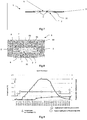
figure 9 illustre sous forme de courbes d'évolution de la température et de la pression en fonction du temps, un exemple de cycle de frittage flash appliqué à l'outillage montré enfigure 8 afin d'obtenir la traversée selon l'invention ; - la
figure 10 illustre schématiquement un empilement représentatif des éléments d'une traversée selon l'invention sur lequel des essais ont été réalisé; - les
figures 11A à 13B sont des reproductions de vues en coupe obtenues par microscope électronique à balayage (MEB) sous différents grossissement d'un empilement illustré schématiquement enfigure 10 ayant subi l'application d'un cycle procédé de frittage flash, à différentes températures.
- the
figure 1 is a diagrammatic perspective exploded view showing the different elements of a lithium-ion accumulator, - the
figure 2 is a front view showing a lithium-ion battery with its flexible packaging according to the state of the art, - the
figure 3 is a perspective view of a lithium-ion battery according to the state of the art with its rigid packaging consisting of a housing; - the
figure 4 is an axial sectional view of a bushing forming a terminal of a Li-ion battery according to an example of the state of the art; - the
figure 5 is an axial sectional view of a bushing forming a terminal of a Li-ion accumulator according to another example of the state of the art; - the
figure 6 is a perspective view of a glass-metal type crossing forming a terminal of a Li-ion accumulator according to another example of the state of the art; - the
figure 7 is an axial sectional view of a bushing, intended to form a terminal of a Li-ion battery according to an example according to the invention; - the
figure 8 is an axial sectional view of a tool in which are housed the various components of a bushing according to the invention, the tooling being adapted to put a flash sintering method; - the
figure 9 illustrates as curves of evolution of temperature and pressure as a function of time, an example of a flash sintering cycle applied to the tooling shown in FIG.figure 8 in order to obtain the crossing according to the invention; - the
figure 10 schematically illustrates a stack representative of the elements of a crossing according to the invention on which tests have been carried out; - the
Figures 11A to 13B are reproductions of sectional views obtained by scanning electron microscope (SEM) under different magnifications of a stack illustrated schematically in FIG.figure 10 having undergone a flash sintering process cycle, at different temperatures.
Les
Par souci de clarté, les mêmes références désignant les mêmes éléments de traversées selon l'état de l'art et selon l'invention sont utilisées pour toutes les
Dans l'ensemble de la présente demande, les termes « inférieur », « supérieur », « bas », « haut », « dessous » et « dessus » sont à comprendre par référence par rapport à un boitier d'accumulateur Li-ion positionné à la verticale avec son couvercle sur le dessus et la traversée faisant saillie à l'extérieur du boitier vers le haut.Throughout the present application, the terms "lower", "upper", "lower", "high", "below" and "above" are to be understood by reference with respect to a Li-ion battery box. positioned vertically with its lid on the top and the bushing protruding outside the housing upwards.
On a représenté en
La traversée 1 selon l'invention est réalisée à travers un orifice non débouchant de part et d'autre d'un couvercle 3 d'un boitier d'accumulateur Li-ion.The
La traversée 1 représentée comprend deux pions 2,de préférence en aluminium, traversant l'orifice 32 fixés à l'intérieur de celui-ci au moyen d'un joint en fritte de verre isolant 5, obtenu par l'application d'un procédé de frittage flash.The
En outre, à chaque extrémité de pion est fixée une feuille métallique 7 qui permet de réaliser la fermeture du boitier d'accumulateur par un moyen de soudure adapté, tel que soudure TIG, laser, soudure par faisceau d'électrons. Plus précisément, la feuille métallique 7 inférieure, c'est-à-dire celle destinée à venir à l'intérieur du boitier d'accumulateur est destinée à être soudée au collecteur de courant de l'un ou l'autre des électrodes de la cellule électrochimique constituant l'accumulateur.In addition, at each end of the pin is fixed a
Pour réaliser la traversée 1 selon l'invention, on peut mettre en oeuvre un outillage 9 en graphite tel que montré schématiquement en
L'outillage 9 comprend une partie supérieure formant un piston de presse 90, une partie inférieure formant un socle 91, le piston 90 étant apte à se déplacer relativement entre des parois périphériques extérieures 92, 93. Les parois périphériques 92 permettent de délimiter un espace à l'intérieur duquel la fritte de verre est confinée, tandis que les parois périphériques 93 les plus à l'extérieur déterminent l'espace de positionnement du couvercle 3.The
Le procédé selon l'invention comprend les étapes suivantes :
- Etape a/ : on positionne le couvercle 3 sur le socle 91 de l'outillage. Au préalable, on intercale une feuille de carbone 8 entre le socle 91 et le couvercle 3, afin d'éviter toute soudure néfaste dans la suite du procédé. Au préalable également, on insère une feuille métallique en
aluminium 7 qui est en contact avec chaque extrémité inférieure depion 2. - Etape b/: on met en place de la partie extérieure 92, 93 de l'outillage autour du couvercle 3.
- Etape c/: on insère en les maintenant les pions métalliques 2 dans l'orifice 32 débouchant de la paroi du couvercle. Puis, on remplit le reste de l'orifice par une fritte de verre 5'.
A titre d'exemple indicatif, la fritte de verre 5' utilisée, peut être celle commercialisée sous la référence commerciale GL57 par la société Ferro. Les éléments chimiques constituant cette fritte de verre avec leur pourcentage pondéral respectif sont les suivants :- oxygène : 43.30%
- carbone: 7.51 %
- silicium: 16.01 %
- aluminium: 0.27%
- sodium: 12.09%
- titane: 12.11%
- phosphore: 1.06%
- potassium: 7.64%.
- Etape d/: on met en place alors le
piston 90 de l'outillage sur unezone intégrant l'orifice 32 rempli de la fritte de verre 5' et dans laquelle les pions 2 sont insérés et maintenus. Au préalable, comme pour l'étape a/, on intercale une feuille de carbone 8 entre le couvercle 3 et lepiston 90 et on insère une feuille métallique enaluminium 7 qui est en contact avec chaque extrémité supérieure depion 2. - Etape e/: on applique un cycle de température et de pression et de déplacement du
piston 90 pour mettre en oeuvre un procédé de frittage flash.
- Step a /: the
lid 3 is positioned on thebase 91 of the tooling. Beforehand, acarbon sheet 8 is interposed between the base 91 and thecover 3, in order to avoid any harmful welding in the rest of the process. Also beforehand, analuminum metal sheet 7 is inserted which is in contact with each lower end ofpin 2. - Step b /: we set up the
outer part cover 3. - Step c /: inserting by maintaining the
metal pins 2 in theopening 32 opening the wall of the lid. Then, the remainder of the orifice is filled with a glass frit 5 '.
By way of indicative example, the glass frit 5 'used may be that marketed under the commercial reference GL57 by the company Ferro. The chemical elements constituting this glass frit with their respective weight percentage are as follows:- oxygen: 43.30%
- carbon: 7.51%
- silicon: 16.01%
- aluminum: 0.27%
- sodium: 12.09%
- Titanium: 12.11%
- phosphorus: 1.06%
- potassium: 7.64%.
- Step d /: the
piston 90 of the tooling is then placed on an area integrating theorifice 32 filled with the glass frit 5 'and in which thepins 2 are inserted and held. In advance, as for step a /, acarbon sheet 8 is inserted between thecover 3 and thepiston 90 and analuminum metal sheet 7 is inserted which is in contact with each upper end of thepin 2. - Step e /: a temperature and pressure cycle and displacement of the
piston 90 are applied to implement a flash sintering process.
Un exemple avantageux de cycle en fonction du temps est illustré sous forme de courbes en
Les inventeurs ont réalisé différents essais d'un empilement alterné de fritte de verre 5' et de pions en aluminium 2 comme montré en
Les
Les
Les
Il ressort de ces vues au MEB une meilleure densification du verre et une meilleure cohésion/contact entre l'Aluminium et la fritte de verre à 500°C comparativement à 480°C et à 450°CThese SEM views show better glass densification and better cohesion / contact between aluminum and glass frit at 500 ° C compared to 480 ° C and 450 ° C.
La traversée 1 selon l'invention peut être réalisée sur un couvercle 3 de boitier d'accumulateur Li-ion aussi bien selon une géométrie cylindrique que selon une géométrie prismatique. Dans ces différentes configurations, la borne 1 selon l'invention est par exemple négative, la borne positive pouvant être réalisée, par exemple directement par soudure, également sur le couvercle 3.The crossing 1 according to the invention can be carried out on a
L'invention n'est pas limitée aux exemples qui viennent d'être décrits ; on peut notamment combiner entre elles des caractéristiques des exemples illustrés au sein de variantes non illustrées.The invention is not limited to the examples which have just been described; it is possible in particular to combine with one another characteristics of the illustrated examples within non-illustrated variants.
D'autres variantes et améliorations peuvent être envisagées sans pour autant sortir du cadre de l'invention.Other variants and improvements may be envisaged without departing from the scope of the invention.
Si dans les modes de réalisation illustrés, le matériau du joint est une fritte de verre, tout matériau électrique isolant peut convenir à la condition d'être relativement proche du point de fusion, et que la température du process de frittage flash soit compatible avec les différents autres matériaux, l'aluminium des pions et du couvercle notamment.If in the embodiments shown, the material of the seal is a glass frit, any insulating electrical material may be suitable provided that it is relatively close to the melting point, and that the temperature of the flash sintering process is compatible with the different other materials, aluminum pions and cover in particular.
Ainsi, pour tout matériau électriquement isolant convenant, il faut veiller à que la température du process de frittage flash oit être légèrement inférieure à la température de fusion.Thus, for any suitable electrically insulating material, it must be ensured that the temperature of the flash sintering process should be slightly lower than the melting temperature.
Dans le mode illustré des
-
[1]:
«Polymers Handbook», FOURTH EDITION. Editors. J. BRANDRUP, E. H. IMMERGUT, and E. A. GRULKE "Polymers Handbook", FOURTH EDITION. Editors. J. BRANDRUP, EH IMMERGUT, and EA GRULKE -
[2] :
Claude ESTOURNES, «Mise en forme de matériaux par frittage flash», Technique de l'ingénieur ; Référence IN56- 10 juillet 2006 Claude ESTOURNES, «Shaping of materials by flash sintering», Engineering Technique; Reference IN56- July 10, 2006
Claims (7)
- Method for making a feedthrough comprising the following steps:a/ positioning of a body (3) comprising a metallic wall (3) with an orifice (10) passing straight through it on a base (91) of a tooling (9), preferably one made of graphite;b/ placing of the outer portion (92, 93) of the tooling around the body;c/ insertion of one or more metallic pins (2) in the orifice emerging from the wall and then filling the rest of the orifice with a frit (5') of electrically insulating material;d/ placing the upper portion of the tool forming a piston (90) against a zone including the orifice filled with the frit of electrically insulating material, preferably a glass frit, and in which the one or more pins is (are) inserted;e/ application of a temperature and pressure cycle, and a displacement of the piston, to carry out a flash sintering process.
- Method according to Claim 1, whereby prior to step a/ and/or step d/ a sheet of carbon paper (8) is placed respectively between the tool base and the body and/or between the body and the tooling piston.
- Method according to Claim 1 or 2, whereby prior to step a/ and/or step d/ a metallic sheet (7) is placed respectively in contact with the lower end of the pin or pins and/or with the upper end of the pin or pins.
- Method according to one of the preceding claims, wherein a metallic sheet (7) is welded to at least one end of a pin (2), the welded sheet forming part of a current collector.
- Method according to one of the preceding claims, the sintered electrically insulating material of the seal (5) being a sintered glass.
- Method according to Claim 5, the sintered glass (5) being based on alkaline oxides.
- Method according to one of the preceding claims, the pin or pins being made of aluminium.
Applications Claiming Priority (1)
| Application Number | Priority Date | Filing Date | Title |
|---|---|---|---|
| FR1561919A FR3044659B1 (en) | 2015-12-07 | 2015-12-07 | WATERPROOF GLASS-METAL THROUGH, USE AS A TERMINAL FOR LITHIUM ELECTROCHEMICAL ACCUMULATOR, ASSOCIATED PROCESS |
Publications (2)
| Publication Number | Publication Date |
|---|---|
| EP3179532A1 EP3179532A1 (en) | 2017-06-14 |
| EP3179532B1 true EP3179532B1 (en) | 2018-08-15 |
Family
ID=55182446
Family Applications (1)
| Application Number | Title | Priority Date | Filing Date |
|---|---|---|---|
| EP16202434.3A Active EP3179532B1 (en) | 2015-12-07 | 2016-12-06 | Glass-metal sealed feed-through, use as lithium electrochemical battery, associated production method |
Country Status (3)
| Country | Link |
|---|---|
| US (1) | US20170162838A1 (en) |
| EP (1) | EP3179532B1 (en) |
| FR (1) | FR3044659B1 (en) |
Families Citing this family (6)
| Publication number | Priority date | Publication date | Assignee | Title |
|---|---|---|---|---|
| FR3055741B1 (en) * | 2016-09-07 | 2018-09-21 | Commissariat A L'energie Atomique Et Aux Energies Alternatives | TRAVERSEE FORMING TERMINAL FOR ELECTROCHEMICAL ACCUMULATOR METAL-ION AND ACCUMULATOR ASSOCIATED |
| US11431047B2 (en) | 2018-05-07 | 2022-08-30 | Apple Inc. | Feedthrough with integrated insulator |
| DE102018209324A1 (en) * | 2018-06-12 | 2019-12-12 | Bayerische Motoren Werke Aktiengesellschaft | Monitoring of batteries |
| US11145925B2 (en) * | 2018-09-06 | 2021-10-12 | Apple Inc. | Cylindrical battery cell with overmolded glass feedthrough |
| US11417926B2 (en) | 2018-11-29 | 2022-08-16 | Apple Inc. | Feedthroughs for thin battery cells |
| CN115395148B (en) * | 2022-08-03 | 2023-06-30 | 江西微电新能源有限公司 | Button cell and electronic equipment |
Family Cites Families (29)
| Publication number | Priority date | Publication date | Assignee | Title |
|---|---|---|---|---|
| US3920172A (en) * | 1974-10-03 | 1975-11-18 | Bendix Corp | Conductive glass seal assembly |
| US3957496A (en) * | 1975-09-23 | 1976-05-18 | The United States Of America As Represented By The United States Energy Research And Development Administration | Molybdenum sealing glass-ceramic composition |
| US4061841A (en) * | 1977-04-15 | 1977-12-06 | General Motors Corporation | Feedthrough assembly for lithium-iron sulfide cell |
| US4178164A (en) * | 1978-05-11 | 1979-12-11 | Gte Sylvania Incorporated | Method for making a glass-to-metal seal for electrochemical cells |
| FR2556123B1 (en) | 1983-12-01 | 1987-02-06 | Ceraver | PROCESS FOR MAKING A WATERPROOF ELECTRICAL WAY THROUGH A WALL |
| US5151118A (en) * | 1988-07-08 | 1992-09-29 | Kabushiki Kaisha Goto Seisakusho | Method for producing a package-type semiconductor assembly |
| US5821011A (en) | 1989-10-11 | 1998-10-13 | Medtronic, Inc. | Body implanted device with electrical feedthrough |
| US6274252B1 (en) * | 1994-08-04 | 2001-08-14 | Coors Ceramics Company | Hermetic glass-to-metal seal useful in headers for airbags |
| US5693580A (en) * | 1996-09-13 | 1997-12-02 | Sandia Corporation | Titanium sealing glasses and seals formed therefrom |
| FR2798227A1 (en) | 1999-09-02 | 2001-03-09 | Cit Alcatel | Passage for current connection terminal passing through the wall of a sealed electrochemical battery providing good sealing without need to weld to case |
| US6759163B2 (en) | 2000-05-04 | 2004-07-06 | Wilson Greatbatch Ltd. | Mismatched compression glass-to-metal seal |
| CN1295799C (en) | 2000-10-13 | 2007-01-17 | 松下电器产业株式会社 | Flat square battery |
| US20030096162A1 (en) | 2001-11-09 | 2003-05-22 | Lasater Brian J. | Lithium-ion battery seal |
| AU2003212786A1 (en) * | 2002-01-09 | 2003-07-30 | Alfred E. Mann Foundation For Scientific Research | Hermetic seals for lithium-ion batteries |
| US7338733B2 (en) | 2002-04-30 | 2008-03-04 | Sanyo Electric Co., Ltd. | Battery pack |
| US7335448B2 (en) | 2002-05-30 | 2008-02-26 | Matsushita Electric Industrial Co., Ltd. | Lithium ion secondary battery |
| JP4324794B2 (en) | 2004-11-09 | 2009-09-02 | ソニー株式会社 | Negative electrode active material and secondary battery |
| US7738538B1 (en) | 2005-08-01 | 2010-06-15 | Ralink Technology Corporation | Flexible and in-band signaling for nested preamble |
| JP4251204B2 (en) | 2006-08-31 | 2009-04-08 | 日産自動車株式会社 | Battery module |
| JP5114036B2 (en) | 2006-09-08 | 2013-01-09 | Necエナジーデバイス株式会社 | Manufacturing method of stacked battery |
| FR2908928B1 (en) | 2006-11-21 | 2009-11-27 | Commissariat Energie Atomique | LITHIUM BATTERY-BASED DRYWAY, ITS MANUFACTURING METHOD AND ITS USE IN A LITHIUM BATTERY, AND LITHIUM BATTERY USING SUCH A TRAVERSEE |
| US20120009464A1 (en) | 2009-03-31 | 2012-01-12 | Makoto Nakazawa | Material for metal case of secondary battery using non-aqueous electrolyte, metal case, secondary battery, and producing method of material for metal case |
| CN201690389U (en) | 2010-08-18 | 2010-12-29 | 王旭 | Solar energy charging pack |
| US20120107672A1 (en) * | 2010-10-29 | 2012-05-03 | Medtronic, Inc. | Electrode With Interconnection Design for Miniature Electrochemical Cells and Methods of Making |
| US10224521B2 (en) * | 2011-02-18 | 2019-03-05 | Schott Ag | Feed-through |
| PL2675768T3 (en) * | 2011-02-18 | 2021-05-31 | Schott Ag | Feed-through |
| CN103620813B (en) * | 2011-06-10 | 2017-11-03 | 肖特公开股份有限公司 | Feedthrough |
| DE102013006463B4 (en) * | 2013-04-15 | 2017-01-19 | Schott Ag | execution |
| FR3019686B1 (en) * | 2014-04-08 | 2016-05-06 | Commissariat Energie Atomique | LITHIUM ELECTROCHEMICAL ACCUMULATOR WITH TERMINAL IN DIRECT CONNECTION WITH THE ELECTROCHEMICAL BEAM, METHODS OF MAKING THE SAME. |
-
2015
- 2015-12-07 FR FR1561919A patent/FR3044659B1/en active Active
-
2016
- 2016-12-06 EP EP16202434.3A patent/EP3179532B1/en active Active
- 2016-12-06 US US15/370,438 patent/US20170162838A1/en not_active Abandoned
Non-Patent Citations (1)
| Title |
|---|
| None * |
Also Published As
| Publication number | Publication date |
|---|---|
| EP3179532A1 (en) | 2017-06-14 |
| US20170162838A1 (en) | 2017-06-08 |
| FR3044659B1 (en) | 2020-02-28 |
| FR3044659A1 (en) | 2017-06-09 |
Similar Documents
| Publication | Publication Date | Title |
|---|---|---|
| EP3179532B1 (en) | Glass-metal sealed feed-through, use as lithium electrochemical battery, associated production method | |
| EP2984697B1 (en) | Lithium electrochemical storage battery having a casing providing improved thermal dissipation, associated battery pack and production processes | |
| EP2842185B1 (en) | Bushing forming a terminal for a lithium storage battery and related storage battery | |
| EP2870655B1 (en) | Current collector with integrated leak-proofing means, bipolar battery comprising such a collector | |
| EP3130020B1 (en) | Lithium-ion electrochemical accumulator having a terminal directly connected to the electrode assembly and associated production methods | |
| EP3499602A1 (en) | System for monitoring the gas within a battery pack, associated metal-ion electrochemical storage cell comprising a crossmember forming a terminal for including a safety vent for the monitoring system | |
| EP2875538B1 (en) | Bipolar li-ion battery with improved seal and associated production process | |
| EP2093820B1 (en) | Electric connection for current accumulator | |
| EP3410514B1 (en) | Bushing forming a terminal for a metal-ion storage cell, including a gas release valve, associated cell | |
| EP3649694B1 (en) | Methods for producing an electrochemical bundle of a metal-ion battery by means of a gel polymer electrolyte membrane, and associated batteries | |
| EP3499606A1 (en) | Part for mechanical interface and electrical insulation between two metal-ion electrochemical storage cells aligned according to their longitudinal axis, associated storage cell module | |
| EP3499603A1 (en) | Crossmember forming a terminal for a metal-ion electrochemical storage cell, associated cell | |
| EP3095147B1 (en) | Electrochemical accumulator with housing and terminal made of aluminum alloy | |
| EP3035411B1 (en) | Method for connection in an accumulator, and accumulator thus connected | |
| EP3510652A1 (en) | Feedthrough forming a terminal for an electrochemical metal-ion battery and associated battery | |
| WO2019092375A2 (en) | Electrochemical accumulator having a specific bipolar architecture | |
| FR3037725A1 (en) | METHOD FOR PRODUCING AN ELECTROCHEMICAL BEAM OF A LITHIUM BATTERY WITH METALLIC FOAM AT THE END OF STRIPS | |
| FR3059159A1 (en) | ELECTRODE FOR ELECTROCHEMICAL BEAM OF A METAL-ION BATTERY WITH HIGH ENERGY DENSITY, CYLINDRICAL OR PRISMATIC ACCUMULATOR | |
| EP3472880A1 (en) | Electrode for an electrochemical bundle of a metal-ion storage battery or a supercapacitor, method for producing the associated bundle and storage battery | |
| FR3129528A1 (en) | Process for producing an all-solid-state battery from a metal-ion electrochemical accumulator with liquid electrolyte, for the purposes of abusive thermal tests. | |
| EP2960964B1 (en) | Electrochemical accumulator with housing assembled by improved welding | |
| CA2249473A1 (en) | Bipolar electrode for battery with alkaline electrolyte | |
| FR3016736A1 (en) | LITHIUM-ION BATTERY (LI-ION) CAPACITY INCREASED BY INCREASE IN HEIGHT AVAILABLE INSIDE THE HOUSING | |
| EP4156391A1 (en) | Busbar for a battery module or battery pack with flexible packaging for electrically connecting at least one battery of the module or pack, and associated method |
Legal Events
| Date | Code | Title | Description |
|---|---|---|---|
| PUAI | Public reference made under article 153(3) epc to a published international application that has entered the european phase |
Free format text: ORIGINAL CODE: 0009012 |
|
| STAA | Information on the status of an ep patent application or granted ep patent |
Free format text: STATUS: THE APPLICATION HAS BEEN PUBLISHED |
|
| AK | Designated contracting states |
Kind code of ref document: A1 Designated state(s): AL AT BE BG CH CY CZ DE DK EE ES FI FR GB GR HR HU IE IS IT LI LT LU LV MC MK MT NL NO PL PT RO RS SE SI SK SM TR |
|
| AX | Request for extension of the european patent |
Extension state: BA ME |
|
| STAA | Information on the status of an ep patent application or granted ep patent |
Free format text: STATUS: REQUEST FOR EXAMINATION WAS MADE |
|
| 17P | Request for examination filed |
Effective date: 20171115 |
|
| RBV | Designated contracting states (corrected) |
Designated state(s): AL AT BE BG CH CY CZ DE DK EE ES FI FR GB GR HR HU IE IS IT LI LT LU LV MC MK MT NL NO PL PT RO RS SE SI SK SM TR |
|
| GRAP | Despatch of communication of intention to grant a patent |
Free format text: ORIGINAL CODE: EPIDOSNIGR1 |
|
| STAA | Information on the status of an ep patent application or granted ep patent |
Free format text: STATUS: GRANT OF PATENT IS INTENDED |
|
| RIC1 | Information provided on ipc code assigned before grant |
Ipc: H01M 4/485 20100101ALI20180131BHEP Ipc: H01M 10/0525 20100101ALI20180131BHEP Ipc: H01M 2/08 20060101ALI20180131BHEP Ipc: H01M 2/30 20060101ALI20180131BHEP Ipc: C03C 8/08 20060101ALI20180131BHEP Ipc: C03C 8/24 20060101ALI20180131BHEP Ipc: C03C 3/097 20060101ALI20180131BHEP Ipc: C03C 27/02 20060101ALI20180131BHEP Ipc: H01M 2/06 20060101AFI20180131BHEP Ipc: C03C 29/00 20060101ALI20180131BHEP Ipc: H01M 2/04 20060101ALI20180131BHEP |
|
| INTG | Intention to grant announced |
Effective date: 20180307 |
|
| GRAS | Grant fee paid |
Free format text: ORIGINAL CODE: EPIDOSNIGR3 |
|
| GRAA | (expected) grant |
Free format text: ORIGINAL CODE: 0009210 |
|
| STAA | Information on the status of an ep patent application or granted ep patent |
Free format text: STATUS: THE PATENT HAS BEEN GRANTED |
|
| AK | Designated contracting states |
Kind code of ref document: B1 Designated state(s): AL AT BE BG CH CY CZ DE DK EE ES FI FR GB GR HR HU IE IS IT LI LT LU LV MC MK MT NL NO PL PT RO RS SE SI SK SM TR |
|
| REG | Reference to a national code |
Ref country code: CH Ref legal event code: EP Ref country code: GB Ref legal event code: FG4D Free format text: NOT ENGLISH Ref country code: AT Ref legal event code: REF Ref document number: 1030789 Country of ref document: AT Kind code of ref document: T Effective date: 20180815 |
|
| REG | Reference to a national code |
Ref country code: IE Ref legal event code: FG4D Free format text: LANGUAGE OF EP DOCUMENT: FRENCH |
|
| REG | Reference to a national code |
Ref country code: DE Ref legal event code: R096 Ref document number: 602016004796 Country of ref document: DE |
|
| REG | Reference to a national code |
Ref country code: NL Ref legal event code: MP Effective date: 20180815 |
|
| REG | Reference to a national code |
Ref country code: LT Ref legal event code: MG4D |
|
| REG | Reference to a national code |
Ref country code: AT Ref legal event code: MK05 Ref document number: 1030789 Country of ref document: AT Kind code of ref document: T Effective date: 20180815 |
|
| PG25 | Lapsed in a contracting state [announced via postgrant information from national office to epo] |
Ref country code: FI Free format text: LAPSE BECAUSE OF FAILURE TO SUBMIT A TRANSLATION OF THE DESCRIPTION OR TO PAY THE FEE WITHIN THE PRESCRIBED TIME-LIMIT Effective date: 20180815 Ref country code: RS Free format text: LAPSE BECAUSE OF FAILURE TO SUBMIT A TRANSLATION OF THE DESCRIPTION OR TO PAY THE FEE WITHIN THE PRESCRIBED TIME-LIMIT Effective date: 20180815 Ref country code: AT Free format text: LAPSE BECAUSE OF FAILURE TO SUBMIT A TRANSLATION OF THE DESCRIPTION OR TO PAY THE FEE WITHIN THE PRESCRIBED TIME-LIMIT Effective date: 20180815 Ref country code: IS Free format text: LAPSE BECAUSE OF FAILURE TO SUBMIT A TRANSLATION OF THE DESCRIPTION OR TO PAY THE FEE WITHIN THE PRESCRIBED TIME-LIMIT Effective date: 20181215 Ref country code: NO Free format text: LAPSE BECAUSE OF FAILURE TO SUBMIT A TRANSLATION OF THE DESCRIPTION OR TO PAY THE FEE WITHIN THE PRESCRIBED TIME-LIMIT Effective date: 20181115 Ref country code: GR Free format text: LAPSE BECAUSE OF FAILURE TO SUBMIT A TRANSLATION OF THE DESCRIPTION OR TO PAY THE FEE WITHIN THE PRESCRIBED TIME-LIMIT Effective date: 20181116 Ref country code: SE Free format text: LAPSE BECAUSE OF FAILURE TO SUBMIT A TRANSLATION OF THE DESCRIPTION OR TO PAY THE FEE WITHIN THE PRESCRIBED TIME-LIMIT Effective date: 20180815 Ref country code: BG Free format text: LAPSE BECAUSE OF FAILURE TO SUBMIT A TRANSLATION OF THE DESCRIPTION OR TO PAY THE FEE WITHIN THE PRESCRIBED TIME-LIMIT Effective date: 20181115 Ref country code: NL Free format text: LAPSE BECAUSE OF FAILURE TO SUBMIT A TRANSLATION OF THE DESCRIPTION OR TO PAY THE FEE WITHIN THE PRESCRIBED TIME-LIMIT Effective date: 20180815 Ref country code: LT Free format text: LAPSE BECAUSE OF FAILURE TO SUBMIT A TRANSLATION OF THE DESCRIPTION OR TO PAY THE FEE WITHIN THE PRESCRIBED TIME-LIMIT Effective date: 20180815 |
|
| PG25 | Lapsed in a contracting state [announced via postgrant information from national office to epo] |
Ref country code: AL Free format text: LAPSE BECAUSE OF FAILURE TO SUBMIT A TRANSLATION OF THE DESCRIPTION OR TO PAY THE FEE WITHIN THE PRESCRIBED TIME-LIMIT Effective date: 20180815 Ref country code: LV Free format text: LAPSE BECAUSE OF FAILURE TO SUBMIT A TRANSLATION OF THE DESCRIPTION OR TO PAY THE FEE WITHIN THE PRESCRIBED TIME-LIMIT Effective date: 20180815 Ref country code: HR Free format text: LAPSE BECAUSE OF FAILURE TO SUBMIT A TRANSLATION OF THE DESCRIPTION OR TO PAY THE FEE WITHIN THE PRESCRIBED TIME-LIMIT Effective date: 20180815 |
|
| PG25 | Lapsed in a contracting state [announced via postgrant information from national office to epo] |
Ref country code: ES Free format text: LAPSE BECAUSE OF FAILURE TO SUBMIT A TRANSLATION OF THE DESCRIPTION OR TO PAY THE FEE WITHIN THE PRESCRIBED TIME-LIMIT Effective date: 20180815 Ref country code: PL Free format text: LAPSE BECAUSE OF FAILURE TO SUBMIT A TRANSLATION OF THE DESCRIPTION OR TO PAY THE FEE WITHIN THE PRESCRIBED TIME-LIMIT Effective date: 20180815 Ref country code: CZ Free format text: LAPSE BECAUSE OF FAILURE TO SUBMIT A TRANSLATION OF THE DESCRIPTION OR TO PAY THE FEE WITHIN THE PRESCRIBED TIME-LIMIT Effective date: 20180815 Ref country code: IT Free format text: LAPSE BECAUSE OF FAILURE TO SUBMIT A TRANSLATION OF THE DESCRIPTION OR TO PAY THE FEE WITHIN THE PRESCRIBED TIME-LIMIT Effective date: 20180815 Ref country code: RO Free format text: LAPSE BECAUSE OF FAILURE TO SUBMIT A TRANSLATION OF THE DESCRIPTION OR TO PAY THE FEE WITHIN THE PRESCRIBED TIME-LIMIT Effective date: 20180815 Ref country code: EE Free format text: LAPSE BECAUSE OF FAILURE TO SUBMIT A TRANSLATION OF THE DESCRIPTION OR TO PAY THE FEE WITHIN THE PRESCRIBED TIME-LIMIT Effective date: 20180815 |
|
| REG | Reference to a national code |
Ref country code: DE Ref legal event code: R097 Ref document number: 602016004796 Country of ref document: DE |
|
| PG25 | Lapsed in a contracting state [announced via postgrant information from national office to epo] |
Ref country code: DK Free format text: LAPSE BECAUSE OF FAILURE TO SUBMIT A TRANSLATION OF THE DESCRIPTION OR TO PAY THE FEE WITHIN THE PRESCRIBED TIME-LIMIT Effective date: 20180815 Ref country code: SM Free format text: LAPSE BECAUSE OF FAILURE TO SUBMIT A TRANSLATION OF THE DESCRIPTION OR TO PAY THE FEE WITHIN THE PRESCRIBED TIME-LIMIT Effective date: 20180815 Ref country code: SK Free format text: LAPSE BECAUSE OF FAILURE TO SUBMIT A TRANSLATION OF THE DESCRIPTION OR TO PAY THE FEE WITHIN THE PRESCRIBED TIME-LIMIT Effective date: 20180815 |
|
| PLBE | No opposition filed within time limit |
Free format text: ORIGINAL CODE: 0009261 |
|
| STAA | Information on the status of an ep patent application or granted ep patent |
Free format text: STATUS: NO OPPOSITION FILED WITHIN TIME LIMIT |
|
| 26N | No opposition filed |
Effective date: 20190516 |
|
| PG25 | Lapsed in a contracting state [announced via postgrant information from national office to epo] |
Ref country code: SI Free format text: LAPSE BECAUSE OF FAILURE TO SUBMIT A TRANSLATION OF THE DESCRIPTION OR TO PAY THE FEE WITHIN THE PRESCRIBED TIME-LIMIT Effective date: 20180815 Ref country code: LU Free format text: LAPSE BECAUSE OF NON-PAYMENT OF DUE FEES Effective date: 20181206 Ref country code: MC Free format text: LAPSE BECAUSE OF FAILURE TO SUBMIT A TRANSLATION OF THE DESCRIPTION OR TO PAY THE FEE WITHIN THE PRESCRIBED TIME-LIMIT Effective date: 20180815 |
|
| REG | Reference to a national code |
Ref country code: IE Ref legal event code: MM4A |
|
| REG | Reference to a national code |
Ref country code: BE Ref legal event code: MM Effective date: 20181231 |
|
| PG25 | Lapsed in a contracting state [announced via postgrant information from national office to epo] |
Ref country code: IE Free format text: LAPSE BECAUSE OF NON-PAYMENT OF DUE FEES Effective date: 20181206 |
|
| PG25 | Lapsed in a contracting state [announced via postgrant information from national office to epo] |
Ref country code: BE Free format text: LAPSE BECAUSE OF NON-PAYMENT OF DUE FEES Effective date: 20181231 |
|
| PG25 | Lapsed in a contracting state [announced via postgrant information from national office to epo] |
Ref country code: MT Free format text: LAPSE BECAUSE OF FAILURE TO SUBMIT A TRANSLATION OF THE DESCRIPTION OR TO PAY THE FEE WITHIN THE PRESCRIBED TIME-LIMIT Effective date: 20180815 |
|
| PGFP | Annual fee paid to national office [announced via postgrant information from national office to epo] |
Ref country code: DE Payment date: 20191216 Year of fee payment: 4 |
|
| PG25 | Lapsed in a contracting state [announced via postgrant information from national office to epo] |
Ref country code: TR Free format text: LAPSE BECAUSE OF FAILURE TO SUBMIT A TRANSLATION OF THE DESCRIPTION OR TO PAY THE FEE WITHIN THE PRESCRIBED TIME-LIMIT Effective date: 20180815 |
|
| PG25 | Lapsed in a contracting state [announced via postgrant information from national office to epo] |
Ref country code: PT Free format text: LAPSE BECAUSE OF FAILURE TO SUBMIT A TRANSLATION OF THE DESCRIPTION OR TO PAY THE FEE WITHIN THE PRESCRIBED TIME-LIMIT Effective date: 20180815 |
|
| PG25 | Lapsed in a contracting state [announced via postgrant information from national office to epo] |
Ref country code: MK Free format text: LAPSE BECAUSE OF NON-PAYMENT OF DUE FEES Effective date: 20180815 Ref country code: HU Free format text: LAPSE BECAUSE OF FAILURE TO SUBMIT A TRANSLATION OF THE DESCRIPTION OR TO PAY THE FEE WITHIN THE PRESCRIBED TIME-LIMIT; INVALID AB INITIO Effective date: 20161206 Ref country code: CY Free format text: LAPSE BECAUSE OF FAILURE TO SUBMIT A TRANSLATION OF THE DESCRIPTION OR TO PAY THE FEE WITHIN THE PRESCRIBED TIME-LIMIT Effective date: 20180815 |
|
| REG | Reference to a national code |
Ref country code: CH Ref legal event code: PL |
|
| REG | Reference to a national code |
Ref country code: DE Ref legal event code: R079 Ref document number: 602016004796 Country of ref document: DE Free format text: PREVIOUS MAIN CLASS: H01M0002060000 Ipc: H01M0050172000 |
|
| PG25 | Lapsed in a contracting state [announced via postgrant information from national office to epo] |
Ref country code: CH Free format text: LAPSE BECAUSE OF NON-PAYMENT OF DUE FEES Effective date: 20191231 Ref country code: LI Free format text: LAPSE BECAUSE OF NON-PAYMENT OF DUE FEES Effective date: 20191231 |
|
| REG | Reference to a national code |
Ref country code: DE Ref legal event code: R119 Ref document number: 602016004796 Country of ref document: DE |
|
| GBPC | Gb: european patent ceased through non-payment of renewal fee |
Effective date: 20201206 |
|
| PG25 | Lapsed in a contracting state [announced via postgrant information from national office to epo] |
Ref country code: DE Free format text: LAPSE BECAUSE OF NON-PAYMENT OF DUE FEES Effective date: 20210701 Ref country code: GB Free format text: LAPSE BECAUSE OF NON-PAYMENT OF DUE FEES Effective date: 20201206 |
|
| PGFP | Annual fee paid to national office [announced via postgrant information from national office to epo] |
Ref country code: FR Payment date: 20231221 Year of fee payment: 8 |