EP3179102A1 - Abluftführung für eine beschichtungsmittelpumpe - Google Patents
Abluftführung für eine beschichtungsmittelpumpe Download PDFInfo
- Publication number
- EP3179102A1 EP3179102A1 EP16002755.3A EP16002755A EP3179102A1 EP 3179102 A1 EP3179102 A1 EP 3179102A1 EP 16002755 A EP16002755 A EP 16002755A EP 3179102 A1 EP3179102 A1 EP 3179102A1
- Authority
- EP
- European Patent Office
- Prior art keywords
- exhaust air
- duct
- exhaust
- switching unit
- muffler
- Prior art date
- Legal status (The legal status is an assumption and is not a legal conclusion. Google has not performed a legal analysis and makes no representation as to the accuracy of the status listed.)
- Granted
Links
Images



Classifications
-
- F—MECHANICAL ENGINEERING; LIGHTING; HEATING; WEAPONS; BLASTING
- F04—POSITIVE - DISPLACEMENT MACHINES FOR LIQUIDS; PUMPS FOR LIQUIDS OR ELASTIC FLUIDS
- F04B—POSITIVE-DISPLACEMENT MACHINES FOR LIQUIDS; PUMPS
- F04B9/00—Piston machines or pumps characterised by the driving or driven means to or from their working members
- F04B9/08—Piston machines or pumps characterised by the driving or driven means to or from their working members the means being fluid
- F04B9/12—Piston machines or pumps characterised by the driving or driven means to or from their working members the means being fluid the fluid being elastic, e.g. steam or air
- F04B9/129—Piston machines or pumps characterised by the driving or driven means to or from their working members the means being fluid the fluid being elastic, e.g. steam or air having plural pumping chambers
- F04B9/131—Piston machines or pumps characterised by the driving or driven means to or from their working members the means being fluid the fluid being elastic, e.g. steam or air having plural pumping chambers with two mechanically connected pumping members
- F04B9/133—Piston machines or pumps characterised by the driving or driven means to or from their working members the means being fluid the fluid being elastic, e.g. steam or air having plural pumping chambers with two mechanically connected pumping members reciprocating movement of the pumping members being obtained by a double-acting elastic-fluid motor
-
- B—PERFORMING OPERATIONS; TRANSPORTING
- B05—SPRAYING OR ATOMISING IN GENERAL; APPLYING FLUENT MATERIALS TO SURFACES, IN GENERAL
- B05B—SPRAYING APPARATUS; ATOMISING APPARATUS; NOZZLES
- B05B9/00—Spraying apparatus for discharge of liquids or other fluent material, without essentially mixing with gas or vapour
- B05B9/03—Spraying apparatus for discharge of liquids or other fluent material, without essentially mixing with gas or vapour characterised by means for supplying liquid or other fluent material
- B05B9/04—Spraying apparatus for discharge of liquids or other fluent material, without essentially mixing with gas or vapour characterised by means for supplying liquid or other fluent material with pressurised or compressible container; with pump
- B05B9/0403—Spraying apparatus for discharge of liquids or other fluent material, without essentially mixing with gas or vapour characterised by means for supplying liquid or other fluent material with pressurised or compressible container; with pump with pumps for liquids or other fluent material
- B05B9/0409—Spraying apparatus for discharge of liquids or other fluent material, without essentially mixing with gas or vapour characterised by means for supplying liquid or other fluent material with pressurised or compressible container; with pump with pumps for liquids or other fluent material the pumps being driven by a hydraulic or a pneumatic fluid
-
- F—MECHANICAL ENGINEERING; LIGHTING; HEATING; WEAPONS; BLASTING
- F04—POSITIVE - DISPLACEMENT MACHINES FOR LIQUIDS; PUMPS FOR LIQUIDS OR ELASTIC FLUIDS
- F04B—POSITIVE-DISPLACEMENT MACHINES FOR LIQUIDS; PUMPS
- F04B23/00—Pumping installations or systems
- F04B23/04—Combinations of two or more pumps
- F04B23/06—Combinations of two or more pumps the pumps being all of reciprocating positive-displacement type
-
- F—MECHANICAL ENGINEERING; LIGHTING; HEATING; WEAPONS; BLASTING
- F04—POSITIVE - DISPLACEMENT MACHINES FOR LIQUIDS; PUMPS FOR LIQUIDS OR ELASTIC FLUIDS
- F04B—POSITIVE-DISPLACEMENT MACHINES FOR LIQUIDS; PUMPS
- F04B39/00—Component parts, details, or accessories, of pumps or pumping systems specially adapted for elastic fluids, not otherwise provided for in, or of interest apart from, groups F04B25/00 - F04B37/00
- F04B39/0027—Pulsation and noise damping means
- F04B39/0055—Pulsation and noise damping means with a special shape of fluid passage, e.g. bends, throttles, diameter changes, pipes
-
- F—MECHANICAL ENGINEERING; LIGHTING; HEATING; WEAPONS; BLASTING
- F04—POSITIVE - DISPLACEMENT MACHINES FOR LIQUIDS; PUMPS FOR LIQUIDS OR ELASTIC FLUIDS
- F04B—POSITIVE-DISPLACEMENT MACHINES FOR LIQUIDS; PUMPS
- F04B39/00—Component parts, details, or accessories, of pumps or pumping systems specially adapted for elastic fluids, not otherwise provided for in, or of interest apart from, groups F04B25/00 - F04B37/00
- F04B39/0027—Pulsation and noise damping means
- F04B39/0055—Pulsation and noise damping means with a special shape of fluid passage, e.g. bends, throttles, diameter changes, pipes
- F04B39/0061—Pulsation and noise damping means with a special shape of fluid passage, e.g. bends, throttles, diameter changes, pipes using muffler volumes
-
- F—MECHANICAL ENGINEERING; LIGHTING; HEATING; WEAPONS; BLASTING
- F04—POSITIVE - DISPLACEMENT MACHINES FOR LIQUIDS; PUMPS FOR LIQUIDS OR ELASTIC FLUIDS
- F04B—POSITIVE-DISPLACEMENT MACHINES FOR LIQUIDS; PUMPS
- F04B43/00—Machines, pumps, or pumping installations having flexible working members
- F04B43/02—Machines, pumps, or pumping installations having flexible working members having plate-like flexible members, e.g. diaphragms
- F04B43/06—Pumps having fluid drive
- F04B43/073—Pumps having fluid drive the actuating fluid being controlled by at least one valve
-
- F—MECHANICAL ENGINEERING; LIGHTING; HEATING; WEAPONS; BLASTING
- F04—POSITIVE - DISPLACEMENT MACHINES FOR LIQUIDS; PUMPS FOR LIQUIDS OR ELASTIC FLUIDS
- F04B—POSITIVE-DISPLACEMENT MACHINES FOR LIQUIDS; PUMPS
- F04B53/00—Component parts, details or accessories not provided for in, or of interest apart from, groups F04B1/00 - F04B23/00 or F04B39/00 - F04B47/00
- F04B53/001—Noise damping
-
- F—MECHANICAL ENGINEERING; LIGHTING; HEATING; WEAPONS; BLASTING
- F04—POSITIVE - DISPLACEMENT MACHINES FOR LIQUIDS; PUMPS FOR LIQUIDS OR ELASTIC FLUIDS
- F04B—POSITIVE-DISPLACEMENT MACHINES FOR LIQUIDS; PUMPS
- F04B7/00—Piston machines or pumps characterised by having positively-driven valving
- F04B7/02—Piston machines or pumps characterised by having positively-driven valving the valving being fluid-actuated
- F04B7/0266—Piston machines or pumps characterised by having positively-driven valving the valving being fluid-actuated the inlet and discharge means being separate members
-
- B—PERFORMING OPERATIONS; TRANSPORTING
- B05—SPRAYING OR ATOMISING IN GENERAL; APPLYING FLUENT MATERIALS TO SURFACES, IN GENERAL
- B05B—SPRAYING APPARATUS; ATOMISING APPARATUS; NOZZLES
- B05B9/00—Spraying apparatus for discharge of liquids or other fluent material, without essentially mixing with gas or vapour
- B05B9/03—Spraying apparatus for discharge of liquids or other fluent material, without essentially mixing with gas or vapour characterised by means for supplying liquid or other fluent material
- B05B9/04—Spraying apparatus for discharge of liquids or other fluent material, without essentially mixing with gas or vapour characterised by means for supplying liquid or other fluent material with pressurised or compressible container; with pump
- B05B9/0403—Spraying apparatus for discharge of liquids or other fluent material, without essentially mixing with gas or vapour characterised by means for supplying liquid or other fluent material with pressurised or compressible container; with pump with pumps for liquids or other fluent material
-
- F—MECHANICAL ENGINEERING; LIGHTING; HEATING; WEAPONS; BLASTING
- F04—POSITIVE - DISPLACEMENT MACHINES FOR LIQUIDS; PUMPS FOR LIQUIDS OR ELASTIC FLUIDS
- F04B—POSITIVE-DISPLACEMENT MACHINES FOR LIQUIDS; PUMPS
- F04B15/00—Pumps adapted to handle specific fluids, e.g. by selection of specific materials for pumps or pump parts
-
- F—MECHANICAL ENGINEERING; LIGHTING; HEATING; WEAPONS; BLASTING
- F04—POSITIVE - DISPLACEMENT MACHINES FOR LIQUIDS; PUMPS FOR LIQUIDS OR ELASTIC FLUIDS
- F04B—POSITIVE-DISPLACEMENT MACHINES FOR LIQUIDS; PUMPS
- F04B49/00—Control, e.g. of pump delivery, or pump pressure of, or safety measures for, machines, pumps, or pumping installations, not otherwise provided for, or of interest apart from, groups F04B1/00 - F04B47/00
- F04B49/22—Control, e.g. of pump delivery, or pump pressure of, or safety measures for, machines, pumps, or pumping installations, not otherwise provided for, or of interest apart from, groups F04B1/00 - F04B47/00 by means of valves
-
- F—MECHANICAL ENGINEERING; LIGHTING; HEATING; WEAPONS; BLASTING
- F04—POSITIVE - DISPLACEMENT MACHINES FOR LIQUIDS; PUMPS FOR LIQUIDS OR ELASTIC FLUIDS
- F04B—POSITIVE-DISPLACEMENT MACHINES FOR LIQUIDS; PUMPS
- F04B53/00—Component parts, details or accessories not provided for in, or of interest apart from, groups F04B1/00 - F04B23/00 or F04B39/00 - F04B47/00
- F04B53/10—Valves; Arrangement of valves
- F04B53/12—Valves; Arrangement of valves arranged in or on pistons
- F04B53/125—Reciprocating valves
- F04B53/126—Ball valves
-
- F—MECHANICAL ENGINEERING; LIGHTING; HEATING; WEAPONS; BLASTING
- F16—ENGINEERING ELEMENTS AND UNITS; GENERAL MEASURES FOR PRODUCING AND MAINTAINING EFFECTIVE FUNCTIONING OF MACHINES OR INSTALLATIONS; THERMAL INSULATION IN GENERAL
- F16L—PIPES; JOINTS OR FITTINGS FOR PIPES; SUPPORTS FOR PIPES, CABLES OR PROTECTIVE TUBING; MEANS FOR THERMAL INSULATION IN GENERAL
- F16L55/00—Devices or appurtenances for use in, or in connection with, pipes or pipe systems
- F16L55/02—Energy absorbers; Noise absorbers
- F16L55/033—Noise absorbers
- F16L55/0336—Noise absorbers by means of sound-absorbing materials
Definitions
- the invention relates to an exhaust air duct for the removal of exhaust air from a pneumatically driven pump, in particular from a coating agent pump in a paint shop.
- the piston can be pressurized on both sides with air pressure, to move the piston in the desired direction.
- the piston in the pneumatic cylinder can deform, for example, two conveyor membranes via a common piston rod, as described in the German patent application DE 10 2013 002 764.0 is described.
- the exhaust air from the pneumatic cylinder is controlled via a switching unit and then discharged through a silencer in the environment, the silencer is flanged directly to the switching unit.
- a disadvantage of these known pumps is the fact that the exhaust air from the pneumatic cylinder is initially under pressure and then expanded, resulting in a strong cooling of the exhaust air.
- the cooling of the exhaust air can lead to an undesirable condensation, so that condensation can accumulate in the exhaust air duct and in particular on the switching unit and on the muffler.
- the expansion-related cooling even so be large, that the condensation freezes and thereby affects the functioning of the switching unit in the worst case.
- Such pumps are for example also off DE 44 25 515 A1 and US 5 094 596 known.
- the invention is therefore based on the object to improve the above-described pneumatically driven pump so that the functionality is not affected by expansion-related cooling of the exhaust air.
- the exhaust air duct according to the invention initially has an inlet in accordance with the prior art to receive the exhaust air from the pneumatically driven pump. Furthermore, in accordance with the prior art, the exhaust air duct according to the invention comprises an outlet in order to deliver the exhaust air to the environment. Between the inlet of the exhaust air duct and the outlet of the exhaust air duct runs in this case in accordance with the prior art, an exhaust duct, in which the exhaust air flows from the inlet to the outlet.
- the exhaust air duct is in this case arranged in a housing body, wherein it should be avoided that the housing body cools so far that the functionality of the functional components in the housing body is impaired.
- the invention is based on the technical-physical knowledge that the heat transfer from the wall of the exhaust duct to the cold exhaust air flow in the exhaust duct is particularly large when the exhaust air stream impinges obtuse or even at right angles to the wall of the exhaust duct.
- This in the context of the invention preferably means that the angle of attack between the exhaust air flow and the wall of the exhaust duct in the range of 30 ° -90 °, 45 ° -90 °, 65 ° -90 °, 80 ° -90 ° or even 85 ° -90 ° is.
- the invention preferably provides that the exhaust air flow in the exhaust duct runs almost completely parallel to the wall of the exhaust duct to prevent the exhaust air flow is incident obtusely or even at right angles to the wall of the exhaust duct, as this leads to a strong heat transfer from the wall would lead to the cold exhaust air flow, which in turn would be associated with a strong cooling of the wall, which is undesirable.
- a change of direction of the exhaust air flow in the exhaust air duct understandably can not be completely avoided.
- the invention therefore provides that in the region of such a change in direction of the exhaust air duct, a heat insulating element is arranged in the exhaust duct, wherein the exhaust air flow then impinges obtusely on the heat insulating element and not on the wall of the exhaust duct.
- the term "obtuse” preferably means that the exhaust air flow with an angle of attack in the range of 30 ° -90 °, 45 ° -90 °, 65 ° -90 °, 80 ° -90 ° or even 85 ° -90 ° on the wall of the heat insulating element impinges.
- the heat insulation element consists of a heat-insulating material (eg plastic), whereas the wall of the exhaust duct otherwise usually consists of metal, which has a much better thermal conductivity than plastic.
- the first heat insulating element thus reduces at an obtuse flow Due to the cold exhaust air intensive cooling of the wall of the exhaust duct and thus also the other components (eg switching unit), which are to be protected from cooling.
- the first heat insulating element clothes the exhaust air duct inside.
- the first heat insulating element is therefore a separate component which is inserted in the exhaust air duct.
- the first heat insulating element is a line component of the exhaust duct.
- a manifold of the exhaust duct may be formed of plastic, whereas the non-curved duct parts of the exhaust duct are made of metal.
- the measures according to the invention described above reduce the heat transfer from the wall of the exhaust duct and from the components to be protected from cooling (for example switching unit) to the cold exhaust air flow, thereby preventing excessive cooling of the components to be protected.
- the invention provides that the exhaust air of the pump cools down considerably at all.
- the invention provides that the exhaust air duct has a cross section which does not expand in the flow direction in order to avoid an expansion of the exhaust air and the associated expansion-related cooling of the exhaust air in the exhaust duct.
- the cross section of the exhaust air duct within the exhaust air duct according to the invention may have a substantially constant size.
- the actual expansion of the exhaust air takes place only downstream downstream of the outlet of the exhaust air duct, for example in a muffler connected thereto.
- the location of the expansion-related cooling is thus laid out in the direction of flow the exhaust air duct in the switching unit in the connected silencer, whereby the components to be protected against cooling (eg switching unit) are cooled less.
- the exhaust air passage extends through the switching unit of the pump.
- the switching unit has the task of controlling the exhaust air from the pneumatically driven pump and / or the supply air to the pneumatically driven pump.
- the exhaust duct of the exhaust air duct according to the invention thus extends through the switching unit and preferably to the silencer.
- the control of the exhaust air of the pneumatically driven pump in the switching unit can be done for example by a diaphragm valve having an elastic membrane for control.
- the elastic membrane can also fulfill the function of the first heat insulation element described above.
- the cold exhaust air thus meets at an obtuse angle on one side of the elastic membrane, which in principle favors the heat transfer from the elastic membrane to the cold exhaust air.
- the elastic membrane is preferably made of a heat-insulating material (e.g., plastic), thereby preventing excessive cooling of the membrane.
- the location of the expansion-related cooling is preferably laid in the direction of flow from the interior of the switching unit into the muffler.
- the invention preferably accepts an expansion-related cooling of the exhaust air in the muffler and thus a corresponding cooling of the muffler itself.
- the invention prevents Preferably, that this cooling of the muffler also leads to a corresponding cooling of the switching unit.
- the invention preferably provides that the silencer is thermally decoupled from the switching unit in order to reduce the heat transfer from the switching unit to the silencer.
- This thermal decoupling is achieved in that the muffler is not connected directly to the switching unit, but by means of a second heat insulating element, which consists of a heat-insulating material (eg plastic).
- the exhaust air duct extends through the switching unit and the second heat insulation element into the muffler.
- the low thermal conductivity of the second heat insulating element has the advantage that the switching unit cools only slightly even with a strong expansion-related cooling of the muffler.
- the heat insulation elements may be made of plastic, while the switching unit, the housing body of the exhaust air duct and / or the wall of the exhaust duct can be made of metal.
- the invention is not limited to these materials in terms of material selection. Rather, it is crucial that the materials of the heat insulation elements have a significantly lower thermal conductivity than the materials of the switching unit, the housing body and / or the wall of the exhaust duct.
- the coating agent pump according to the invention preferably has two oppositely arranged delivery cylinders, each with a displaceable piston, wherein the two pistons are connected in the delivery cylinders with a common piston rod and therefore driven in opposite directions.
- the piston in the pneumatic cylinder can in this case be acted upon on both sides with compressed air to move the piston in the pneumatic cylinder and thus also the two pistons in the delivery cylinders in the desired direction.
- a check valve which closes during a discharge stroke of the respective piston and is open during a Aufhellhubes.
- an exhaust air duct according to the invention can also be implemented in other pumps which are pneumatically driven and convey other fluids, such as adhesives or sealants (for example for seam sealing),
- the drawings show a coating agent pump according to the invention for the promotion of paint in a paint shop for painting motor vehicle body components.
- the paint to be delivered is taken in this case via a pump inlet 1 and discharged via a pump outlet 2 with the desired delivery pressure.
- the actual promotion takes place here by two delivery cylinders 3, 4, in each of which a delivery piston 5, 6 is slidably disposed.
- the two delivery cylinders 3, 4 each have a coating agent inlet 7, 8 and in each case a coating agent outlet 9, 10.
- the pump inlet 1 is connected via a pipe 11 to the two coating agent inlets 7, 8 of the delivery cylinders 3, 4.
- the pump outlet 2 is connected in the same way via a pipe 12 to the two coating agent outlets 9, 10 of the delivery cylinders 3, 4.
- the check valve 13 closes in the delivery piston 6 when the delivery piston 6 during a discharge stroke in FIG. 2 moved from right to left.
- the check valve 13 opens so that new coating agent can flow through the check inlet 13 through the check inlet 13 to the left side of the delivery piston 5.
- a non-return valve 15, 16 is also located in the two coating agent outlets 9, 10.
- the two check valves 15, 16 each open during a discharge stroke of the associated delivery piston 5, 6 and otherwise close.
- the mechanical drive of the two delivery pistons 5, 6 takes place via a common piston rod 17, so that the two delivery pistons 5, 6 always move in opposite directions. This means that in the case of the two delivery pistons 5, 6, the discharge stroke and the charge-up stroke each run in opposite phase.
- the mechanical drive of the common piston rod 17 is effected by a pneumatic piston 18, which is arranged in a pneumatic cylinder 19 and can be acted upon on both sides with compressed air.
- the Figures 2 and 3 show the pneumatic piston 18 in each case at a dead center.
- two switching valves 21, 22 are arranged, which are actuated by the pneumatic piston 18 when the pneumatic piston 18 is one of his reached both dead points.
- the pneumatic piston 18 is activated in the Figures 2 and 3 the switching valve 22.
- the two switching valves 21, 22 control the exhaust air from the pneumatic cylinder 19 on both sides of the pneumatic piston 18.
- the exhaust air from the pneumatic cylinder 19 is then discharged through an exhaust duct, wherein the exhaust air passage through a switching unit 23 into two silencers 24, 25 leads.
- a switching unit 23 here is a spool 26, the in FIG. 4 can be moved in the vertical direction, wherein the position of the spool 26 is pneumatically adjusted via the switching valves 21, 22.
- the position of the spool 26 in the switching unit 23 in turn controls two diaphragm valves 27, 28, which are arranged in the exhaust duct of the exhaust duct and release or block the exhaust air flow by means of a respective elastic valve membrane 29, 30 made of plastic.
- FIG. 4 the diaphragm valve 27 is shown in a closed position while the diaphragm valve 28 is opened on the opposite side.
- the invention is now characterized by the special structural design of the exhaust duct from the pneumatic cylinder 19.
- the exhaust air duct has an inlet 31, at which the exhaust air from the pneumatic cylinder 19 is received.
- the exhaust air then flows through an exhaust duct 32, to an outlet 33 to which the muffler 24 and 25 is connected.
- the exhaust duct 32 already belongs to the silencer 24 or 25.
- the exhaust air is then expanded in the muffler 24 and 25, which leads to a corresponding cooling of the exhaust air and thus also of the muffler 24 and 25 respectively.
- the muffler 24 or 25 is thermally decoupled from the switching unit 23 by a heat insulation element 34 or 35, wherein the exhaust air channel 32 extends through the heat insulation element 34 or 35 to the respective muffler 24 or 25. This thermal decoupling by the heat insulating element 34 or 35 ensures that the unavoidable strong cooling of the muffler 24 or 25 does not lead to excessive cooling of the switching unit 23.
- the exhaust air flow in the exhaust duct 32 in the region of change of direction does not impinge on the metal housing of the switching unit 23, but on the heat insulation element 32 or on the valve diaphragm 30 made of plastic.
- This is advantageous because a right-angled Flow of a housing part through the cold exhaust air a good heat transfer and thus a strong cooling of the housing part are favored. It is therefore useful to provide in these areas with a strong change in direction heat insulation elements.
- the invention is not limited to the preferred embodiment described above. Rather, a variety of variants and modifications is possible, which also make use of the inventive idea.
- the invention also claims protection for the subject matter and the features of the subclaims independently of the claims in each case referred to and in particular without the features of the main claim.
- the idea of thermal decoupling of the silencer on the one hand and the switching unit on the other hand also enjoys its own protective significance due to a heat-insulating element.
Landscapes
- Engineering & Computer Science (AREA)
- General Engineering & Computer Science (AREA)
- Mechanical Engineering (AREA)
- Details Of Reciprocating Pumps (AREA)
- Reciprocating Pumps (AREA)
- Compressor (AREA)
- Pipe Accessories (AREA)
Abstract
Description
- Die Erfindung betrifft eine Abluftführung zur Abführung von Abluft von einer pneumatisch angetriebenen Pumpe, insbesondere von einer Beschichtungsmittelpumpe in einer Lackieranlage.
- In modernen Lackieranlagen zur Lackierung von Kraftfahrzeug-Karosseriebauteilen werden zur Förderung des zu applizierenden Lacks oftmals pneumatisch angetriebene Pumpen eingesetzt, die zum Antrieb einen Pneumatikzylinder und einen Kolben aufweisen, der in dem Pneumatikzylinder verschiebbar angeordnet ist, wobei der Kolben beidseitig mit Luftdruck beaufschlagt werden kann, um den Kolben in der gewünschten Richtung zu verschieben. Der Kolben in dem Pneumatikzylinder kann über eine gemeinsame Kolbenstange beispielsweise zwei Fördermembranen verformen, wie es in der deutschen Patentanmeldung
DE 10 2013 002 764.0 beschrieben ist. Die Abluft aus dem Pneumatikzylinder wird hierbei über eine Umschalteinheit gesteuert und dann durch einen Schalldämpfer in die Umgebung abgegeben, wobei der Schalldämpfer direkt an die Umschalteinheit angeflanscht ist. - Nachteilig an diesen bekannten Pumpen ist die Tatsache, dass die Abluft aus dem Pneumatikzylinder zunächst unter Druck steht und dann expandiert, was zu einer starken Abkühlung der Abluft führt. Die Abkühlung der Abluft kann zu einer unerwünschten Kondenswasserbildung führen, so dass sich Kondenswasser in der Abluftführung und insbesondere auf der Umschalteinheit und auf dem Schalldämpfer ansammeln kann. Im Extremfall kann die expansionsbedingte Abkühlung sogar so groß sein, dass das Kondenswasser gefriert und dadurch im schlimmsten Fall die Funktionsfähigkeit der Umschalteinheit beeinträchtigt.
- Derartige Pumpen sind beispielsweise auch aus
DE 44 25 515 A1 undUS 5 094 596 bekannt. - Der Erfindung liegt deshalb die Aufgabe zugrunde, die vorstehend beschriebene pneumatisch angetriebene Pumpe so zu verbessern, dass die Funktionsfähigkeit durch expansionsbedingte Abkühlungen der Abluft nicht beeinträchtigt wird.
- Diese Aufgabe wird durch eine erfindungsgemäße Abluftführung gemäß dem Hauptanspruch gelöst.
- Die erfindungsgemäße Abluftführung weist zunächst in Übereinstimmung mit dem Stand der Technik einen Einlass auf, um die Abluft von der pneumatisch angetriebenen Pumpe aufzunehmen. Weiterhin umfasst die erfindungsgemäße Abluftführung in Übereinstimmung mit dem Stand der Technik einen Auslass, um die Abluft an die Umgebung abzugeben. Zwischen dem Einlass der Abluftführung und dem Auslass der Abluftführung verläuft hierbei in Übereinstimmung mit dem Stand der Technik ein Abluftkanal, in dem die Abluft von dem Einlass zu dem Auslass strömt. Der Abluftkanal ist hierbei in einem Gehäusekörper angeordnet, wobei vermieden werden sollte, dass der Gehäusekörper so weit abkühlt, dass die Funktionsfähigkeit der Funktionskomponenten in dem Gehäusekörper beeinträchtigt wird.
- Die Erfindung beruht auf der technisch-physikalischen Erkenntnis, dass der Wärmeübergang von der Wandung des Abluftkanals auf den kalten Abluftstrom in dem Abluftkanal besonders groß ist, wenn der Abluftstrom stumpfwinklig oder gar rechtwinklig auf die Wandung des Abluftkanals auftrifft. Dies bedeutet im Rahmen der Erfindung vorzugsweise, dass der Anströmwinkel zwischen dem Abluftstrom und der Wandung des Abluftkanals im Bereich von 30°-90°, 45°-90°, 65°-90°, 80°-90° oder sogar 85°-90° liegt.
- Die Erfindung sieht deshalb vorzugsweise vor, dass die Abluftströmung in dem Abluftkanal nahezu vollständig parallel zu der Wandung des Abluftkanals verläuft, um zu verhindern, dass die Abluftströmung stumpfwinklig oder gar rechtwinklig auf die Wandung des Abluftkanals auftrifft, da dies zu einem starken Wärmeübergang von der Wandung auf die kalte Abluftströmung führen würde, was wiederum mit einer starken Abkühlung der Wandung verbunden wäre, was unerwünscht ist.
- Allerdings lässt sich eine Richtungsänderung der Abluftströmung in der Abluftführung verständlicherweise nicht vollständig vermeiden. Die Erfindung sieht deshalb vor, dass im Bereich einer solchen Richtungsänderung des Abluftkanals ein Wärmeisolationselement in dem Abluftkanal angeordnet ist, wobei die Abluftströmung dann stumpfwinklig auf das Wärmeisolationselement auftrifft und nicht auf die Wandung des Abluftkanals. Auch hierbei bedeutet der Begriff "stumpfwinklig" vorzugsweise, dass die Abluftströmung mit einem Anströmwinkel im Bereich von 30°-90°, 45°-90°, 65°-90°, 80°-90° oder sogar 85°-90° auf die Wandung des Wärmeisolationselements auftrifft. Zwar staut sich die kalte Abluft dann ebenfalls an dem Wärmeisolationselement, was grundsätzlich den Wärmeübergang von dem Wärmeisolationselement auf die kalte Abluft begünstigt. Allerdings besteht das Wärmeisolationselement aus einem wärmeisolierenden Material (z.B. Kunststoff), wohingegen die Wandung des Abluftkanals ansonsten in der Regel aus Metall besteht, was eine wesentlich bessere Wärmeleitfähigkeit aufweist als Kunststoff. Das erste Wärmeisolationselement verringert also bei einer stumpfwinkligen Anströmung durch die kalte Abluft eine intensive Abkühlung der Wandung des Abluftkanals und damit auch der sonstigen Bauteile (z.B. Umschalteinheit), die vor einer Abkühlung zu schützen sind.
- In einer Variante der Erfindung kleidet das erste Wärmeisolationselement den Abluftkanal innen aus. Das erste Wärmeisolationselement ist hierbei also ein separates Bauteil, das in dem Abluftkanal eingesetzt ist. In einer anderen Variante der Erfindung ist das erste Wärmeisolationselement dagegen ein Leitungsbestandteil des Abluftkanals. Beispielsweise kann ein Krümmer des Abluftkanals aus Kunststoff ausgebildet sein, wohingegen die ungekrümmten Leitungsteile des Abluftkanals aus Metall bestehen.
- Die vorstehend beschriebenen erfindungsgemäßen Maßnahmen verringern den Wärmeübergang von der Wandung des Abluftkanals und von den vor einer Abkühlung zu schützenden Komponenten (z.B. Umschalteinheit) auf die kalte Abluftströmung und verhindern dadurch eine zu starke Abkühlung der zu schützenden Komponenten.
- Eine andere erfindungsgemäße Maßnahme sieht dagegen vor, dass sich die Abluft der Pumpe überhaupt stark abkühlt. Hierzu sieht die Erfindung vor, dass der Abluftkanal einen Querschnitt aufweist, der sich in Strömungsrichtung nicht aufweitet, um eine Expansion der Abluft und die damit verbundene expansionsbedingte Abkühlung der Abluft in dem Abluftkanal zu vermeiden. Beispielsweise kann der Querschnitt des Abluftkanals innerhalb der erfindungsgemäßen Abluftführung eine im Wesentlichen konstante Größe aufweisen. Die eigentliche Expansion der Abluft erfolgt dann erst stromabwärts hinter dem Auslass der Abluftführung, beispielsweise in einem daran angeschlossenen Schalldämpfer. Der Ort der expansionsbedingten Abkühlung wird hierbei also in Strömungsrichtung verlegt aus der Abluftführung in der Umschalteinheit in den angeschlossenen Schalldämpfer, wodurch die vor einer Abkühlung zu schützenden Komponenten (z.B. Umschalteinheit) weniger stark abgekühlt werden.
- In einem bevorzugten Ausführungsbeispiel der Erfindung verläuft die Abluftführung durch die Umschalteinheit der Pumpe. Die Umschalteinheit hat hierbei die Aufgabe, die Abluft aus der pneumatisch angetriebenen Pumpe und/oder die Zuluft zu der pneumatisch angetriebenen Pumpe zu steuern. Der Abluftkanal der erfindungsgemäßen Abluftführung verläuft hierbei also durch die Umschalteinheit hindurch und vorzugsweise zu dem Schalldämpfer.
- Die Steuerung der Abluft der pneumatisch angetriebenen Pumpe in der Umschalteinheit kann beispielsweise durch ein Membranventil erfolgen, das zur Steuerung eine elastische Membran aufweist. Die elastische Membran kann hierbei ebenfalls die Funktion des vorstehend beschriebenen ersten Wärmeisolationselementes erfüllen. Im geöffneten Zustand des Membranventils trifft die kalte Abluft also stumpfwinklig auf die eine Seite der elastischen Membran, was grundsätzlich den Wärmeübergang von der elastischen Membran auf die kalte Abluft begünstigt. Die elastische Membran besteht jedoch vorzugsweise aus einem wärmeisolierenden Material (z.B. Kunststoff), wodurch eine übermäßige Abkühlung der Membran verhindert wird.
- Es wurde bereits vorstehend erwähnt, dass der Ort der expansionsbedingten Abkühlung vorzugsweise in Strömungsrichtung verlegt wird vom Inneren der Umschalteinheit in den Schalldämpfer hinein. Die Erfindung akzeptiert also vorzugsweise eine expansionsbedingte Abkühlung der Abluft in dem Schalldämpfer und damit auch eine entsprechende Abkühlung des Schalldämpfers selbst. Allerdings verhindert die Erfindung vorzugsweise, dass diese Abkühlung des Schalldämpfers auch zu einer entsprechenden Abkühlung der Umschalteinheit führt. Hierzu sieht die Erfindung vorzugsweise vor, dass der Schalldämpfer thermisch von der Umschalteinheit entkoppelt wird, um den Wärmeübergang von der Umschalteinheit auf den Schalldämpfer zu verringern. Diese thermische Entkopplung wird dadurch erreicht, dass der Schalldämpfer nicht direkt an die Umschalteinheit angeschlossen wird, sondern mittels eines zweiten Wärmeisolationselements, das aus einem wärmeisolierenden Material (z.B. Kunststoff) besteht. Der Abluftkanal verläuft hierbei also durch die Umschalteinheit und das zweite Wärmeisolationselement hindurch in den Schalldämpfer. Die geringe Wärmeleitfähigkeit des zweiten Wärmeisolationselements hat den Vorteil, dass sich die Umschalteinheit auch bei einer starken expansionsbedingten Abkühlung des Schalldämpfers nur geringfügig abkühlt.
- Es wurde bereits vorstehend kurz erwähnt, dass die Wärmeisolationselemente aus Kunststoff bestehen können, während die Umschalteinheit, der Gehäusekörper der Abluftführung und/oder die Wandung des Abluftkanals aus Metall bestehen können. Die Erfindung ist jedoch hinsichtlich der Materialauswahl nicht auf diese Materialien beschränkt. Entscheidend ist vielmehr, dass die Materialien der Wärmeisolationselemente eine wesentlich geringere Wärmeleitfähigkeit aufweisen als die Materialien der Umschalteinheit, des Gehäusekörpers und/oder der Wandung des Abluftkanals.
- Ferner ist zu erwähnen, dass die Erfindung nicht nur Schutz beansprucht für die vorstehend beschriebene erfindungsgemäße Abluftführung. Vielmehr beansprucht die Erfindung auch Schutz für eine entsprechende Beschichtungsmittelpumpe mit einer erfindungsgemäßen Abluftführung.
- Die erfindungsgemäße Beschichtungsmittelpumpe weist vorzugsweise zwei gegenüberliegend angeordnete Förderzylinder mit jeweils einem verschiebbaren Kolben auf, wobei die beiden Kolben in den Förderzylindern mit einer gemeinsamen Kolbenstange verbunden sind und deshalb in entgegengesetzten Richtungen angetrieben werden. Der Antrieb der Kolbenstange und damit auch der Antrieb der beiden Kolben in den Förderzylindern erfolgt über einen Pneumatikzylinder, in dem ein weiterer Kolben angeordnet ist, der auf die gemeinsame Kolbenstange wirkt. Der Kolben in dem Pneumatikzylinder kann hierbei beidseitig mit Druckluft beaufschlagt werden, um den Kolben in dem Pneumatikzylinder und damit auch die beiden Kolben in den Förderzylindern in der gewünschten Richtung zu bewegen.
- In den beiden Kolben in den Förderzylindern befindet sich vorzugsweise jeweils ein Rückschlagventil, das während eines Ausstoßhubes des jeweiligen Kolbens schließt und während eines Auffüllhubes geöffnet ist.
- Schließlich ist noch zu erwähnen, dass die Erfindung nicht beschränkt ist auf Abluftführungen von Lackpumpen, d.h. Pumpen, die Lack fördern. Vielmehr kann eine erfindungsgemäße Abluftführung auch bei anderen Pumpen realisiert werden, die pneumatisch angetrieben sind und andere Fluide fördern, wie beispielsweise Klebstoffe oder Dichtstoffe (z.B. zur Nahtabdichtung),
- Andere vorteilhafte Weiterbildungen der Erfindung sind in den Unteransprüchen gekennzeichnet oder werden nachstehend zusammen mit der Beschreibung des bevorzugten Ausführungsbeispiels der Erfindung anhand der Figuren näher erläutert. Es zeigen:
- Figur 1
- eine Perspektivansicht einer erfindungsgemäßen Beschichtungsmittelpumpe zur Lackförderung in einer Lackieranlage,
- Figur 2
- eine Querschnittsansicht der Beschichtungsmittelpumpe aus
Figur 1 , - Figur 3
- eine andere Querschnittsansicht durch die Beschichtungsmittelpumpe gemäß den
Figuren 2 und3 , - Figur 4
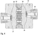
- eine Querschnittsansicht durch die Umschalteinheit der Beschichtungsmittelpumpe aus den
Figuren 1-3 , sowie - Figur 5
- eine andere Querschnittsansicht der Umschalteinheit.
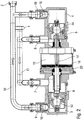
- Die Zeichnungen zeigen eine erfindungsgemäße Beschichtungsmittelpumpe zur Förderung von Lack in einer Lackieranlage zur Lackierung von Kraftfahrzeug-Karosseriebauteilen.
- Der zu fördernde Lack wird hierbei über einen Pumpeneinlass 1 aufgenommen und über einen Pumpenauslass 2 mit dem gewünschten Förderdruck abgegeben. Die eigentliche Förderung erfolgt hierbei durch zwei Förderzylinder 3, 4, in denen jeweils ein Förderkolben 5, 6 verschiebbar angeordnet ist.
- Die beiden Förderzylinder 3, 4 weisen jeweils einen Beschichtungsmitteleinlass 7, 8 und jeweils einen Beschichtungsmittelauslass 9, 10 auf. Der Pumpeneinlass 1 ist über ein Rohr 11 mit den beiden Beschichtungsmitteleinlässen 7, 8 der Förderzylinder 3, 4 verbunden. Der Pumpenauslass 2 ist in gleicher Weise über ein Rohr 12 mit den beiden Beschichtungsmittelauslässen 9, 10 der Förderzylinder 3, 4 verbunden.
- In den beiden Förderkolben 5, 6 befindet sich jeweils ein Rückschlagventil 13, 14, das nur in einer Richtung öffnet. So schließt das Rückschlagventil 13 in dem Förderkolben 6, wenn sich der Förderkolben 6 während eines Ausstoßhubs in
Figur 2 von rechts nach links bewegt. Bei einer Bewegung des Förderkolbens 6 in der entgegengesetzten Richtung von links nach rechts öffnet das Rückschlagventil 13 dagegen, damit über den Beschichtungsmitteleinlass 7 neues Beschichtungsmittel durch das Rückschlagventil 13 hindurch auf die linke Seite des Förderkolbens 5 strömen kann. - Hierbei ist zu erwähnen, dass sich in den beiden Beschichtungsmittelauslässen 9, 10 ebenfalls jeweils ein Rückschlagventil 15, 16 befindet. Die beiden Rückschlagventile 15, 16 öffnen jeweils während eines Ausstoßhubes des zugehörigen Förderkolbens 5, 6 und schließen ansonsten.
- Der mechanische Antrieb der beiden Förderkolben 5, 6 erfolgt über eine gemeinsame Kolbenstange 17, so dass sich die beiden Förderkolben 5, 6 immer in entgegengesetzten Richtungen bewegen. Dies bedeutet, dass bei den beiden Förderkolben 5, 6 der Ausstoßhub und der Auffüllhub jeweils gegenphasig verlaufen.
- Der mechanische Antrieb der gemeinsamen Kolbenstange 17 erfolgt durch einen Pneumatikkolben 18, der in einem Pneumatikzylinder 19 angeordnet ist und beidseitig mit Druckluft beaufschlagt werden kann. Die
Figuren 2 und3 zeigen den Pneumatikkolben 18 hierbei jeweils an einem Totpunkt. - In einem Gehäuse 20 des Pneumatikzylinders 19 sind zwei Umschaltventile 21, 22 angeordnet, die von dem Pneumatikkolben 18 betätigt werden, wenn der Pneumatikkolben 18 einen seiner beiden Totpunkte erreicht. So aktiviert der Pneumatikkolben 18 in den
Figuren 2 und3 das Umschaltventil 22. - Die beiden Umschaltventile 21, 22 steuern die Abluft aus dem Pneumatikzylinder 19 auch beiderseits des Pneumatikkolbens 18. Die Abluft aus dem Pneumatikzylinder 19 wird dann durch eine Abluftführung abgeführt, wobei die Abluftführung durch eine Umschalteinheit 23 in zwei Schalldämpfer 24, 25 führt. In der Umschalteinheit 23 befindet sich hierbei ein Steuerschieber 26, der in
Figur 4 in senkrechter Richtung verschoben werden kann, wobei die Stellung des Steuerschiebers 26 pneumatisch über die Umschaltventile 21, 22 eingestellt wird. Die Stellung des Steuerschiebers 26 in der Umschalteinheit 23 steuert wiederum zwei Membranventile 27, 28 an, die in dem Abluftkanal der Abluftführung angeordnet sind und mittels jeweils einer elastischen Ventilmembran 29, 30 aus Kunststoff den Abluftstrom freigeben oder sperren. - In
Figur 4 ist das Membranventil 27 in einer geschlossenen Stellung gezeigt, während das Membranventil 28 auf der gegenüberliegenden Seite geöffnet ist. - Die Erfindung zeichnet sich nun durch die besondere konstruktive Gestaltung der Abluftführung aus dem Pneumatikzylinder 19 aus.
- Zunächst ist zu erwähnen, dass die Abluftführung einen Einlass 31 aufweist, an dem die Abluft aus dem Pneumatikzylinder 19 aufgenommen wird. Die Abluft strömt dann durch einen Abluftkanal 32, zu einem Auslass 33, an dem der Schalldämpfer 24 bzw. 25 angeschlossen ist. Der Abluftkanal 32 gehört hierbei bereits zu dem Schalldämpfer 24 bzw. 25.
- Wichtig ist hierbei zunächst, dass der Querschnitt des Abluftkanals 32 zwischen dem Einlass 31 und dem Auslass 33 nahezu konstant ist, so dass es in dem Abluftkanal 32 nicht zu einer Expansion der Abluft kommt, so dass auch keine expansionsbedingte Abkühlung auftritt. Dadurch wird bereits verhindert, dass es im Bereich der Umschalteinheit 23 zu einer wesentlichen Abkühlung kommt, die zur Bildung von Kondenswasser und im schlimmsten Fall zu Eisbildung führen könnte, wodurch sogar die Funktionsfähigkeit der Umschalteinheit 23 beeinträchtigt werden könnte.
- Allerdings wird die Abluft dann in dem Schalldämpfer 24 bzw. 25 expandiert, was zu einer entsprechenden Abkühlung der Abluft und damit auch des Schalldämpfers 24 bzw. 25 führt. Der Schalldämpfer 24 bzw. 25 ist jedoch erfindungsgemäß durch ein Wärmeisolationselement 34 bzw. 35 thermisch von der Umschalteinheit 23 entkoppelt, wobei der Abluftkanal 32 durch das Wärmeisolationselement 34 bzw. 35 hindurch zu dem jeweiligen Schalldämpfer 24 bzw. 25 verläuft. Diese thermische Entkopplung durch das Wärmeisolationselement 34 bzw. 35 sorgt dafür, dass die nicht vermeidbare starke Abkühlung des Schalldämpfers 24 bzw. 25 nicht zu einer übermäßigen Abkühlung der Umschalteinheit 23 führt.
- Weiterhin ist zu erwähnen, dass die Abluftströmung in dem Abluftkanal 32 im Bereich von Richtungsänderung nicht auf das aus Metall bestehende Gehäuse der Umschalteinheit 23 auftrifft, sondern auf das Wärmeisolationselement 32 oder auf die aus Kunststoff bestehende Ventilmembran 30. Dies ist vorteilhaft, weil durch eine rechtwinklige Anströmung eines Gehäuseteils durch die kalte Abluft ein guter Wärmeübergang und damit eine starke Abkühlung des Gehäuseteils begünstigt werden. Es ist deshalb sinnvoll, in diesen Bereichen mit einer starken Richtungsänderung Wärmeisolationselemente vorzusehen.
- Die Erfindung ist nicht auf das vorstehend beschriebene bevorzugte Ausführungsbeispiel beschränkt. Vielmehr ist eine Vielzahl von Varianten und Abwandlungen möglich, die ebenfalls von dem Erfindungsgedanken Gebrauch machen. Insbesondere beansprucht die Erfindung auch Schutz für den Gegenstand und die Merkmale der Unteransprüche unabhängig von den jeweils in Bezug genommenen Ansprüchen und insbesondere ohne die Merkmale des Hauptanspruchs. Beispielsweise genießt auch der Gedanke einer thermischen Entkopplung von Schalldämpfer einerseits und Umschalteinheit andererseits durch ein Wärmeisolationselement eine eigene schutzwürdige Bedeutung.
-
- 1
- Pumpeneinlass
- 2
- Pumpenauslass
- 3
- Förderzylinder
- 4
- Förderzylinder
- 5
- Förderkolben im Förderzylinder
- 6
- Förderkolben im Förderzylinder
- 7
- Beschichtungsmitteleinlass am Förderzylinder
- 8
- Beschichtungsmitteleinlass am Förderzylinder
- 9
- Beschichtungsmittelauslass am Förderzylinder
- 10
- Beschichtungsmittelauslass am Förderzylinder
- 11
- Rohr
- 12
- Rohr
- 13
- Rückschlagventil im Förderkolben
- 14
- Rückschlagventil im Förderkolben
- 15
- Rückschlagventil im Beschichtungsmittelauslass
- 16
- Rückschlagventil im Beschichtungsmittelauslass
- 17
- Kolbenstange
- 18
- Pneumatikkolben
- 19
- Pneumatikzylinder
- 20
- Gehäuse des Pneumatikzylinders
- 21
- Umschaltventil
- 22
- Umschaltventil
- 23
- Umschalteinheit
- 24
- Schalldämpfer
- 25
- Schalldämpfer
- 26
- Steuerschieber in der Umschalteinheit
- 27
- Membranventil
- 28
- Membranventil
- 29
- Ventilmembran
- 30
- Ventilmembran
- 31
- Einlass der Abluftführung
- 32
- Abluftkanal
- 33
- Auslass der Abluftführung
- 34
- Wärmeisolationselement
- 35
- Wärmeisolationselement
Claims (8)
- Abluftführung zur Abführung von Abluft von einer pneumatisch angetriebenen Pumpe, insbesondere von einer Beschichtungsmittelpumpe in einer Lackieranlage, mita) einem Einlass (31) zur Aufnahme der Abluft von der Pumpe,b) einem Auslass (33) zur Abgabe der Abluft, undc) einem Abluftkanal (32), in dem die Abluft von dem Einlass zu dem Auslass der Abluftführung strömt, undd) einem Gehäusekörper (23), in dem der Abluftkanal (32) verläuft,e) einem Schalldämpfer (24, 25), der an den Auslass (33) der Abluftführung angeschlossen ist, so dass die Abluft aus dem Auslass (33) der Abluftführung in den Schalldämpfer (24, 25) strömt, dann in dem Schalldämpfer (24, 25) expandiert und schließlich aus dem Schalldämpfer (24, 25) in die Umgebung abgegeben wird, undf) einer Umschalteinheit (23) zum Umschalten der Pumpe, insbesondere zwischen entgegengesetzten Bewegungsrichtungen eines pneumatisch angetriebenen Kolbens (18) der Pumpe, wobei die Umschalteinheit (23) in dem Gehäusekörper (23) angeordnet ist und der Abluftkanal (32) durch die Umschalteinheit (23) hindurch zu dem Schalldämpfer (24, 25) verläuft,dadurch gekennzeichnet,g) dass die Umschalteinheit (23) durch ein erstes Wärmeisolationselement (34, 35) mechanisch mit dem Schalldämpfer (24, 25) verbunden ist, wobei der Abluftkanal (32) durch das erste Wärmeisolationselement (34, 35) hindurch zu dem Schalldämpfer (24, 25) verläuft, undh) dass das erste Wärmeisolationselement (34, 35) den Schalldämpfer (24, 25) thermisch von der Umschalteinheit (23) entkoppelt, um den Wärmeübergang von der Umschalteinheit (23) auf den Schalldämpfer (24, 25) zu verringern.
- Abluftführung nach Anspruch 1, dadurch gekennzeichnet, dass die Abluft im Bereich einer Richtungsänderung des Abluftkanals (32) stumpfwinklig auf ein zweites Wärmeisolationselement (29, 30, 34, 35) in dem Abluftkanal (32) trifft, das heißt mit einem Anströmwinkel von 30°-90° zwischen dem Abluftstrom und der Wandung des Wärmeisolationselements (29, 30, 34, 35), um ein Aufstauen der Abluft direkt an der Innenwand des Abluftkanals (32) zu vermeiden und dadurch die Abkühlung des Gehäusekörpers (23) zu verringern.
- Abluftführung nach Anspruch 1 oder 2,
dadurch gekennzeichnet,a) dass der Abluftkanal (32) einen Querschnitt aufweist, der sich in Strömungsrichtung nicht aufweitet, um eine Expansion der Abluft und eine expansionsbedingte Abkühlung der Abluft in dem Abluftkanal (32) zu vermeiden, und/oderb) dass der Querschnitt des Ablaufkanals in Strömungsrichtung eine im Wesentlichen konstante Größe aufweist. - Abluftführung nach einem der vorhergehenden Ansprüche,
dadurch gekennzeichnet, dass die Umschalteinheit (23) ein Membranventil (27, 28) aufweist mit einer elastischen Membran (29, 30), wobei das zweite Wärmeisolationselement die Membran (29, 30) bildet. - Abluftführung nach einem der vorhergehenden Ansprüche,
dadurch gekennzeichnet,a) dass das erste Wärmeisolationselement (29, 30, 34, 35) aus Kunststoff besteht, und/oderb) dass das zweite Wärmeisolationselement (34, 35) aus Kunststoff besteht, und/oderc) dass die Umschalteinheit (23) im Wesentlichen aus Metall besteht, und/oderd) dass der Gehäusekörper im Wesentlichen aus Metall besteht, und/odere) dass der Abluftkanal (32) eine Wandung aus Metall aufweist, und/oderf) dass das erste und/oder zweite Wärmeisolationselement (29, 30, 34, 35) aus einem Material besteht, das eine geringe Wärmeleitfähigkeit aufweist als das Material der Umschalteinheit ((23), des Gehäusekörpers (23) und/oder der Wandung des Abluftkanals (32). - Beschichtungsmittelpumpe mit einer Abluftführung nach einem der vorhergehenden Ansprüche.
- Beschichtungsmittelpumpe nach Anspruch 6, gekennzeichnet durcha) einen ersten Förderzylinder (3),b) einen ersten Kolben (6), der in dem ersten Förderzylinder (3) verschiebbar angeordnet ist,c) einen zweiten Förderzylinder (4),d) einen zweiten Kolben (5), der in dem zweiten Förderzylinder (4) verschiebbar angeordnet ist,e) einen Beschichtungsmitteleinlass (7, 8), der in die beiden Förderzylinder (3, 4) mündet,f) einen Beschichtungsmittelauslass (9, 10), der in die beiden Förderzylinder (3, 4) mündet,g) eine Kolbenstange (17), die den ersten Kolben (6) und den zweiten Kolben (5) antreibt,h) einen Pneumatikzylinder (19), undi) einen dritten Kolben (18), der in dem Pneumatikzylinder (19) angeordnet ist und die Kolbenstange (17) antreibt.
- Beschichtungsmittelpumpe nach Anspruch 7,
dadurch gekennzeichnet,a) dass in dem ersten Kolben (6) ein erstes Rückschlagventil (13) angeordnet ist, und/oderb) dass in dem zweiten Kolben (5) ein zweites Rückschlagventil (14) angeordnet ist, und/oderc) dass in dem Beschichtungsmittelauslass (9) an dem ersten Förderzylinder (3) ein drittes Rückschlagventil (15) angeordnet ist, und/oderd) dass in dem Beschichtungsmittelauslass (10) an dem zweiten Förderzylinder (4) ein viertes Rückschlagventil (16) angeordnet ist, und/odere) dass die Umschalteinheit (23) die Zuluft in den Pneumatikzylinder (19) und/oder die Abluft aus dem Pneumatikzylinder (19) steuert, und/oderf) dass der erste Kolben (6) und der zweite Kolben (5) und der dritte Kolben (18) koaxial angeordnet sind und jeweils fest mit der Kolbenstange (17) verbunden sind.
Priority Applications (1)
| Application Number | Priority Date | Filing Date | Title |
|---|---|---|---|
| PL16002755T PL3179102T3 (pl) | 2014-05-08 | 2015-05-04 | Odprowadzenie powietrza odlotowego dla pompy środka powlekającego |
Applications Claiming Priority (3)
| Application Number | Priority Date | Filing Date | Title |
|---|---|---|---|
| DE102014006759.9A DE102014006759A1 (de) | 2014-05-08 | 2014-05-08 | Abluftführung für eine Beschichtungsmittelpumpe |
| EP15720602.0A EP2951437B1 (de) | 2014-05-08 | 2015-05-04 | Abluftführung für eine beschichtungsmittelpumpe |
| PCT/EP2015/000908 WO2015144317A1 (de) | 2014-05-08 | 2015-05-04 | Abluftführung für eine beschichtungsmittelpumpe |
Related Parent Applications (2)
| Application Number | Title | Priority Date | Filing Date |
|---|---|---|---|
| EP15720602.0A Division EP2951437B1 (de) | 2014-05-08 | 2015-05-04 | Abluftführung für eine beschichtungsmittelpumpe |
| EP15720602.0A Division-Into EP2951437B1 (de) | 2014-05-08 | 2015-05-04 | Abluftführung für eine beschichtungsmittelpumpe |
Publications (2)
| Publication Number | Publication Date |
|---|---|
| EP3179102A1 true EP3179102A1 (de) | 2017-06-14 |
| EP3179102B1 EP3179102B1 (de) | 2019-12-18 |
Family
ID=53052789
Family Applications (2)
| Application Number | Title | Priority Date | Filing Date |
|---|---|---|---|
| EP16002755.3A Active EP3179102B1 (de) | 2014-05-08 | 2015-05-04 | Abluftführung für eine beschichtungsmittelpumpe |
| EP15720602.0A Active EP2951437B1 (de) | 2014-05-08 | 2015-05-04 | Abluftführung für eine beschichtungsmittelpumpe |
Family Applications After (1)
| Application Number | Title | Priority Date | Filing Date |
|---|---|---|---|
| EP15720602.0A Active EP2951437B1 (de) | 2014-05-08 | 2015-05-04 | Abluftführung für eine beschichtungsmittelpumpe |
Country Status (9)
| Country | Link |
|---|---|
| US (1) | US10697443B2 (de) |
| EP (2) | EP3179102B1 (de) |
| CN (1) | CN106573260B (de) |
| DE (1) | DE102014006759A1 (de) |
| ES (2) | ES2629054T3 (de) |
| HU (1) | HUE034590T2 (de) |
| PL (2) | PL2951437T3 (de) |
| PT (1) | PT2951437T (de) |
| WO (1) | WO2015144317A1 (de) |
Families Citing this family (8)
| Publication number | Priority date | Publication date | Assignee | Title |
|---|---|---|---|---|
| BR102013024307B1 (pt) * | 2013-09-23 | 2022-03-29 | Drausuisse Brasil Comércio E Locação De Unidades Hidráulicas Inteligentes S.A. | Unidade geradora de pressão hidráulica com acionamento pneumático |
| DE102018100637B3 (de) * | 2018-01-12 | 2019-06-06 | Dürr Systems Ag | Dichtung und Beschichtungsmittelpumpe mit einer solchen Dichtung |
| FR3094394B1 (fr) * | 2019-03-28 | 2021-04-09 | Exel Ind | Silencieux de pompe pneumatique, pompe pneumatique comprenant un tel silencieux et installation de projection de produit de revêtement comportant au moins une telle pompe pneumatique |
| CN110821816B (zh) * | 2019-10-31 | 2022-01-28 | 烟台丰亿泵业有限公司 | 一种便于实时排出泵腔内多余空气的柱塞泵 |
| IT202000009730A1 (it) * | 2020-05-04 | 2021-11-04 | Nuovo Pignone Tecnologie Srl | Compressore alternativo con involucro attorno all'asta del pistone |
| WO2022137269A1 (en) * | 2020-12-21 | 2022-06-30 | Meclube S.R.L. | An industrial pneumatic pump for a viscous fluid |
| CN119036997B (zh) * | 2024-08-23 | 2025-03-21 | 翌江新材(江苏)有限公司 | 一种片材气凝胶成品自动剥离工作台及其剥离方法 |
| FR3166670A1 (fr) * | 2024-09-20 | 2026-03-27 | Exel Industries | Ensemble de pompe avec refroidissement du système hydraulique |
Citations (4)
| Publication number | Priority date | Publication date | Assignee | Title |
|---|---|---|---|---|
| US5094596A (en) | 1990-06-01 | 1992-03-10 | Binks Manufacturing Company | High pressure piston pump for fluent materials |
| DE4425515A1 (de) | 1993-07-20 | 1995-03-09 | Graco Inc | Doppelmembranpumpe mit einer zweistufigen Luftventilbetätigungseinrichtung |
| US20050249612A1 (en) * | 2004-05-10 | 2005-11-10 | Chris Distaso | Reciprocating air distribution system |
| US20130101445A1 (en) * | 2010-03-26 | 2013-04-25 | Promera GmbH & Co, KG | Double diaphragm pump |
Family Cites Families (34)
| Publication number | Priority date | Publication date | Assignee | Title |
|---|---|---|---|---|
| US1923333A (en) * | 1930-10-08 | 1933-08-22 | Louis N Strike | Compressor |
| US2858767A (en) * | 1955-10-13 | 1958-11-04 | Neil V Smith | Pumping apparatus |
| US3282167A (en) * | 1964-04-09 | 1966-11-01 | Walker Mfg Co | Reciprocating fluid motor |
| US4035109A (en) * | 1975-08-25 | 1977-07-12 | Drath Edwin H | Pump for fluent, and especially heavy and abrasive materials |
| DE2626954C2 (de) * | 1976-06-16 | 1985-04-11 | Schmidt, Kranz & Co Gmbh, Zweigniederlassung Maschinenbau, 3421 Zorge | Steuerschieberanordnung für eine durch Druckluft angetriebene Hydraulikpumpe |
| DE2659835A1 (de) * | 1976-09-24 | 1978-03-30 | Fink Chemie | Vorrichtung zum aufschaeumen von fluessigkeiten |
| US4350266A (en) * | 1979-06-08 | 1982-09-21 | Binks Manufacturing Company | Pumping system for unstable fluids |
| US4373874A (en) * | 1979-07-30 | 1983-02-15 | Albert Phillips | Fluid actuated pump system |
| FR2575792A1 (fr) * | 1985-01-09 | 1986-07-11 | Eimco Secoma | Amplificateur de pression hydraulique |
| US4730991A (en) * | 1986-07-29 | 1988-03-15 | James M. Greentree | Gas actuated proportioning pump |
| USD302557S (en) * | 1987-02-17 | 1989-08-01 | Graco Inc. | Pump |
| US4780065A (en) * | 1987-09-25 | 1988-10-25 | William Sayers | Cylinder pump having an air sensor activated reversing valve |
| US4981418A (en) * | 1989-07-25 | 1991-01-01 | Osmonics, Inc. | Internally pressurized bellows pump |
| US5228842A (en) * | 1991-07-30 | 1993-07-20 | Wagner Spray Tech Corporation | Quick-change fluid section for piston-type paint pumps |
| US5423662A (en) * | 1993-04-22 | 1995-06-13 | Binks Manufacturing Company | Precision metered multiple fluid pumping system |
| US5324175A (en) * | 1993-05-03 | 1994-06-28 | Northern Research & Engineering Corporation | Pneumatically operated reciprocating piston compressor |
| US5494194A (en) * | 1993-12-10 | 1996-02-27 | White Consolidated Industries, Inc. | Viscous material dispenser |
| US5415531A (en) * | 1994-04-06 | 1995-05-16 | Binks Manufacturing Company | Piston pump for fluent materials |
| US5535926A (en) * | 1994-07-06 | 1996-07-16 | Axia Incorporated | Apparatus for applying mastic to a selected surface |
| US5584666A (en) * | 1994-10-17 | 1996-12-17 | Ingersoll-Rand Company | Reduced icing air valve |
| US5520520A (en) * | 1995-03-28 | 1996-05-28 | Nakamoto; Tomijiko | Pneumatically operated double acting pump for viscous food stuffs |
| US5649813A (en) * | 1995-04-20 | 1997-07-22 | Ingersoll-Rand Company | Chamber insulation for prevention of icing in air motors |
| US5626467A (en) * | 1996-04-04 | 1997-05-06 | Teledyne Industries, Inc. | Modular pump |
| US5860794A (en) * | 1997-04-10 | 1999-01-19 | Graco Inc | Double diaphragm pump with air valve block moving in a rectangular pattern |
| US5927954A (en) * | 1996-05-17 | 1999-07-27 | Wilden Pump & Engineering Co. | Amplified pressure air driven diaphragm pump and pressure relief value therefor |
| US5957670A (en) * | 1997-08-26 | 1999-09-28 | Wilden Pump & Engineering Co. | Air driven diaphragm pump |
| US6152705A (en) * | 1998-07-15 | 2000-11-28 | Wilden Pump & Engineering Co. | Air drive pumps and components therefor |
| TW517141B (en) * | 2001-12-28 | 2003-01-11 | Nanya Technology Corp | Liquid supplying device |
| DE10300280A1 (de) * | 2003-01-08 | 2004-07-22 | Itw Gema Ag | Pumpeneinrichtung für Pulver, Verfahren hierfür und Pulverbeschichtungseinrichtung |
| US7168928B1 (en) * | 2004-02-17 | 2007-01-30 | Wilden Pump And Engineering Llc | Air driven hydraulic pump |
| US7381035B2 (en) * | 2004-04-14 | 2008-06-03 | Nordson Corporation | Piston pump with check shaft |
| GB0520878D0 (en) * | 2005-10-14 | 2005-11-23 | Stamper Eric S | Improved pump |
| US7399168B1 (en) * | 2005-12-19 | 2008-07-15 | Wilden Pump And Engineering Llc | Air driven diaphragm pump |
| DE102013003620B4 (de) | 2013-02-18 | 2016-02-04 | Dürr Systems GmbH | Beschichtungsmittelpumpe und Reinigungsverfahren für eine Beschichtungsmittelpumpe |
-
2014
- 2014-05-08 DE DE102014006759.9A patent/DE102014006759A1/de not_active Withdrawn
-
2015
- 2015-05-04 WO PCT/EP2015/000908 patent/WO2015144317A1/de not_active Ceased
- 2015-05-04 EP EP16002755.3A patent/EP3179102B1/de active Active
- 2015-05-04 HU HUE15720602A patent/HUE034590T2/en unknown
- 2015-05-04 US US15/309,448 patent/US10697443B2/en active Active
- 2015-05-04 PL PL15720602T patent/PL2951437T3/pl unknown
- 2015-05-04 ES ES15720602.0T patent/ES2629054T3/es active Active
- 2015-05-04 PT PT157206020T patent/PT2951437T/pt unknown
- 2015-05-04 EP EP15720602.0A patent/EP2951437B1/de active Active
- 2015-05-04 CN CN201580024122.7A patent/CN106573260B/zh active Active
- 2015-05-04 PL PL16002755T patent/PL3179102T3/pl unknown
- 2015-05-04 ES ES16002755T patent/ES2772142T3/es active Active
Patent Citations (4)
| Publication number | Priority date | Publication date | Assignee | Title |
|---|---|---|---|---|
| US5094596A (en) | 1990-06-01 | 1992-03-10 | Binks Manufacturing Company | High pressure piston pump for fluent materials |
| DE4425515A1 (de) | 1993-07-20 | 1995-03-09 | Graco Inc | Doppelmembranpumpe mit einer zweistufigen Luftventilbetätigungseinrichtung |
| US20050249612A1 (en) * | 2004-05-10 | 2005-11-10 | Chris Distaso | Reciprocating air distribution system |
| US20130101445A1 (en) * | 2010-03-26 | 2013-04-25 | Promera GmbH & Co, KG | Double diaphragm pump |
Also Published As
| Publication number | Publication date |
|---|---|
| CN106573260A (zh) | 2017-04-19 |
| HUE034590T2 (en) | 2018-02-28 |
| PL2951437T3 (pl) | 2017-09-29 |
| PT2951437T (pt) | 2017-06-20 |
| DE102014006759A1 (de) | 2015-11-12 |
| ES2629054T3 (es) | 2017-08-07 |
| WO2015144317A1 (de) | 2015-10-01 |
| CN106573260B (zh) | 2019-05-14 |
| PL3179102T3 (pl) | 2020-06-15 |
| EP2951437A1 (de) | 2015-12-09 |
| ES2772142T3 (es) | 2020-07-07 |
| US10697443B2 (en) | 2020-06-30 |
| EP2951437B1 (de) | 2017-03-15 |
| US20170152841A1 (en) | 2017-06-01 |
| EP3179102B1 (de) | 2019-12-18 |
Similar Documents
| Publication | Publication Date | Title |
|---|---|---|
| EP2951437B1 (de) | Abluftführung für eine beschichtungsmittelpumpe | |
| EP1762712B1 (de) | Bypassventil für Verbrennungskraftmaschinen | |
| EP2553270B1 (de) | Ventil zum alternierenden befüllen zweier arbeitsräume eines kolben-zylinder-systems einer pumpe | |
| DE112005000734T5 (de) | Ventilvorrichtung | |
| EP2919961B1 (de) | Schlauchkopf mit trifunktionellem bauteil und verfahren zum optimieren der wanddicke eines schmelzeschlauchs | |
| EP2025978A2 (de) | Wegeventil für eine Scheibenreinigungsvorrichtung in einem Kraftfahrzeug | |
| WO2021001148A1 (de) | Ventilplatte mit ventillamellen | |
| DE102012003709A1 (de) | Abgasführungsanordnung für einen aufladbaren oder aufgeladenen Verbrennungsmotor | |
| DE102017110541B4 (de) | Klimakompressor und Kältemittelkreis mit einem solchen Klimakompressor | |
| DE102016216004A1 (de) | In ihrem Hubvolumen verstellbare hydrostatische Axialkolbenmaschine in Schrägscheibenbauweise, insbesondere hydrostatische Axialkolbenpumpe | |
| EP2977665A2 (de) | Flanschverbindungsanordnung für eine kältemittelleitung und flansch | |
| DE102009005998A1 (de) | Hydraulische Antriebsvorrichtung mit zwei Druckräumen und Verfahren zum Betreiben einer hydraulischen Antriebsvorrichtung mit zwei Druckräumen | |
| EP1372172A1 (de) | Druckgasschalter | |
| DE102014105236A1 (de) | Schmiervorrichtung für die Versorgung von Lagerstellen innerhalb eines Kurbelgehäuses eines Verbrennungsmotors | |
| DE2113602A1 (de) | Absperrorgan mit druckentlastetem Verschlussorgan | |
| DE102009043568A1 (de) | Sicherheitsventil | |
| EP3180223B1 (de) | Schienenfahrzeug mit klimaanlage | |
| DE102005017918A1 (de) | Überdrucksicherheitseinrichtung für einen Kältemittelkreislauf | |
| DE19820102B4 (de) | Oszillier-Zylinder | |
| DE102005008938B4 (de) | Pumpvorrichtung und Verfahren zur kontinuierlichen Förderung breiiger Massen | |
| DE102015114761A1 (de) | Elektro-pneumatische Steuereinheit für ein Stellgerät | |
| DE3922197A1 (de) | Selbstdichtendes ventil | |
| EP3069023B1 (de) | Heissschlammpumpe | |
| DE102006025696A1 (de) | Kolben-Zylinder-Einheit | |
| DE102014216263B3 (de) | Dampfventilvorrichtung |
Legal Events
| Date | Code | Title | Description |
|---|---|---|---|
| PUAI | Public reference made under article 153(3) epc to a published international application that has entered the european phase |
Free format text: ORIGINAL CODE: 0009012 |
|
| STAA | Information on the status of an ep patent application or granted ep patent |
Free format text: STATUS: THE APPLICATION HAS BEEN PUBLISHED |
|
| AC | Divisional application: reference to earlier application |
Ref document number: 2951437 Country of ref document: EP Kind code of ref document: P |
|
| AK | Designated contracting states |
Kind code of ref document: A1 Designated state(s): AL AT BE BG CH CY CZ DE DK EE ES FI FR GB GR HR HU IE IS IT LI LT LU LV MC MK MT NL NO PL PT RO RS SE SI SK SM TR |
|
| STAA | Information on the status of an ep patent application or granted ep patent |
Free format text: STATUS: REQUEST FOR EXAMINATION WAS MADE |
|
| 17P | Request for examination filed |
Effective date: 20170817 |
|
| RBV | Designated contracting states (corrected) |
Designated state(s): AL AT BE BG CH CY CZ DE DK EE ES FI FR GB GR HR HU IE IS IT LI LT LU LV MC MK MT NL NO PL PT RO RS SE SI SK SM TR |
|
| GRAP | Despatch of communication of intention to grant a patent |
Free format text: ORIGINAL CODE: EPIDOSNIGR1 |
|
| STAA | Information on the status of an ep patent application or granted ep patent |
Free format text: STATUS: GRANT OF PATENT IS INTENDED |
|
| RIC1 | Information provided on ipc code assigned before grant |
Ipc: F04B 9/133 20060101AFI20190621BHEP Ipc: B05B 9/04 20060101ALI20190621BHEP Ipc: F04B 43/073 20060101ALI20190621BHEP |
|
| INTG | Intention to grant announced |
Effective date: 20190725 |
|
| GRAS | Grant fee paid |
Free format text: ORIGINAL CODE: EPIDOSNIGR3 |
|
| GRAA | (expected) grant |
Free format text: ORIGINAL CODE: 0009210 |
|
| STAA | Information on the status of an ep patent application or granted ep patent |
Free format text: STATUS: THE PATENT HAS BEEN GRANTED |
|
| AC | Divisional application: reference to earlier application |
Ref document number: 2951437 Country of ref document: EP Kind code of ref document: P |
|
| AK | Designated contracting states |
Kind code of ref document: B1 Designated state(s): AL AT BE BG CH CY CZ DE DK EE ES FI FR GB GR HR HU IE IS IT LI LT LU LV MC MK MT NL NO PL PT RO RS SE SI SK SM TR |
|
| REG | Reference to a national code |
Ref country code: CH Ref legal event code: EP |
|
| REG | Reference to a national code |
Ref country code: IE Ref legal event code: FG4D Free format text: LANGUAGE OF EP DOCUMENT: GERMAN |
|
| REG | Reference to a national code |
Ref country code: DE Ref legal event code: R096 Ref document number: 502015011288 Country of ref document: DE |
|
| REG | Reference to a national code |
Ref country code: AT Ref legal event code: REF Ref document number: 1214888 Country of ref document: AT Kind code of ref document: T Effective date: 20200115 |
|
| REG | Reference to a national code |
Ref country code: NL Ref legal event code: MP Effective date: 20191218 |
|
| PG25 | Lapsed in a contracting state [announced via postgrant information from national office to epo] |
Ref country code: LT Free format text: LAPSE BECAUSE OF FAILURE TO SUBMIT A TRANSLATION OF THE DESCRIPTION OR TO PAY THE FEE WITHIN THE PRESCRIBED TIME-LIMIT Effective date: 20191218 Ref country code: GR Free format text: LAPSE BECAUSE OF FAILURE TO SUBMIT A TRANSLATION OF THE DESCRIPTION OR TO PAY THE FEE WITHIN THE PRESCRIBED TIME-LIMIT Effective date: 20200319 Ref country code: FI Free format text: LAPSE BECAUSE OF FAILURE TO SUBMIT A TRANSLATION OF THE DESCRIPTION OR TO PAY THE FEE WITHIN THE PRESCRIBED TIME-LIMIT Effective date: 20191218 Ref country code: NO Free format text: LAPSE BECAUSE OF FAILURE TO SUBMIT A TRANSLATION OF THE DESCRIPTION OR TO PAY THE FEE WITHIN THE PRESCRIBED TIME-LIMIT Effective date: 20200318 Ref country code: BG Free format text: LAPSE BECAUSE OF FAILURE TO SUBMIT A TRANSLATION OF THE DESCRIPTION OR TO PAY THE FEE WITHIN THE PRESCRIBED TIME-LIMIT Effective date: 20200318 Ref country code: SE Free format text: LAPSE BECAUSE OF FAILURE TO SUBMIT A TRANSLATION OF THE DESCRIPTION OR TO PAY THE FEE WITHIN THE PRESCRIBED TIME-LIMIT Effective date: 20191218 Ref country code: LV Free format text: LAPSE BECAUSE OF FAILURE TO SUBMIT A TRANSLATION OF THE DESCRIPTION OR TO PAY THE FEE WITHIN THE PRESCRIBED TIME-LIMIT Effective date: 20191218 |
|
| REG | Reference to a national code |
Ref country code: LT Ref legal event code: MG4D |
|
| PG25 | Lapsed in a contracting state [announced via postgrant information from national office to epo] |
Ref country code: RS Free format text: LAPSE BECAUSE OF FAILURE TO SUBMIT A TRANSLATION OF THE DESCRIPTION OR TO PAY THE FEE WITHIN THE PRESCRIBED TIME-LIMIT Effective date: 20191218 Ref country code: HR Free format text: LAPSE BECAUSE OF FAILURE TO SUBMIT A TRANSLATION OF THE DESCRIPTION OR TO PAY THE FEE WITHIN THE PRESCRIBED TIME-LIMIT Effective date: 20191218 |
|
| PG25 | Lapsed in a contracting state [announced via postgrant information from national office to epo] |
Ref country code: AL Free format text: LAPSE BECAUSE OF FAILURE TO SUBMIT A TRANSLATION OF THE DESCRIPTION OR TO PAY THE FEE WITHIN THE PRESCRIBED TIME-LIMIT Effective date: 20191218 |
|
| REG | Reference to a national code |
Ref country code: ES Ref legal event code: FG2A Ref document number: 2772142 Country of ref document: ES Kind code of ref document: T3 Effective date: 20200707 |
|
| PG25 | Lapsed in a contracting state [announced via postgrant information from national office to epo] |
Ref country code: NL Free format text: LAPSE BECAUSE OF FAILURE TO SUBMIT A TRANSLATION OF THE DESCRIPTION OR TO PAY THE FEE WITHIN THE PRESCRIBED TIME-LIMIT Effective date: 20191218 Ref country code: RO Free format text: LAPSE BECAUSE OF FAILURE TO SUBMIT A TRANSLATION OF THE DESCRIPTION OR TO PAY THE FEE WITHIN THE PRESCRIBED TIME-LIMIT Effective date: 20191218 Ref country code: PT Free format text: LAPSE BECAUSE OF FAILURE TO SUBMIT A TRANSLATION OF THE DESCRIPTION OR TO PAY THE FEE WITHIN THE PRESCRIBED TIME-LIMIT Effective date: 20200513 Ref country code: EE Free format text: LAPSE BECAUSE OF FAILURE TO SUBMIT A TRANSLATION OF THE DESCRIPTION OR TO PAY THE FEE WITHIN THE PRESCRIBED TIME-LIMIT Effective date: 20191218 |
|
| PG25 | Lapsed in a contracting state [announced via postgrant information from national office to epo] |
Ref country code: IS Free format text: LAPSE BECAUSE OF FAILURE TO SUBMIT A TRANSLATION OF THE DESCRIPTION OR TO PAY THE FEE WITHIN THE PRESCRIBED TIME-LIMIT Effective date: 20200418 Ref country code: SK Free format text: LAPSE BECAUSE OF FAILURE TO SUBMIT A TRANSLATION OF THE DESCRIPTION OR TO PAY THE FEE WITHIN THE PRESCRIBED TIME-LIMIT Effective date: 20191218 Ref country code: SM Free format text: LAPSE BECAUSE OF FAILURE TO SUBMIT A TRANSLATION OF THE DESCRIPTION OR TO PAY THE FEE WITHIN THE PRESCRIBED TIME-LIMIT Effective date: 20191218 |
|
| REG | Reference to a national code |
Ref country code: DE Ref legal event code: R097 Ref document number: 502015011288 Country of ref document: DE |
|
| PLBE | No opposition filed within time limit |
Free format text: ORIGINAL CODE: 0009261 |
|
| STAA | Information on the status of an ep patent application or granted ep patent |
Free format text: STATUS: NO OPPOSITION FILED WITHIN TIME LIMIT |
|
| PG25 | Lapsed in a contracting state [announced via postgrant information from national office to epo] |
Ref country code: DK Free format text: LAPSE BECAUSE OF FAILURE TO SUBMIT A TRANSLATION OF THE DESCRIPTION OR TO PAY THE FEE WITHIN THE PRESCRIBED TIME-LIMIT Effective date: 20191218 |
|
| 26N | No opposition filed |
Effective date: 20200921 |
|
| PG25 | Lapsed in a contracting state [announced via postgrant information from national office to epo] |
Ref country code: SI Free format text: LAPSE BECAUSE OF FAILURE TO SUBMIT A TRANSLATION OF THE DESCRIPTION OR TO PAY THE FEE WITHIN THE PRESCRIBED TIME-LIMIT Effective date: 20191218 |
|
| PG25 | Lapsed in a contracting state [announced via postgrant information from national office to epo] |
Ref country code: CH Free format text: LAPSE BECAUSE OF NON-PAYMENT OF DUE FEES Effective date: 20200531 Ref country code: MC Free format text: LAPSE BECAUSE OF FAILURE TO SUBMIT A TRANSLATION OF THE DESCRIPTION OR TO PAY THE FEE WITHIN THE PRESCRIBED TIME-LIMIT Effective date: 20191218 Ref country code: LI Free format text: LAPSE BECAUSE OF NON-PAYMENT OF DUE FEES Effective date: 20200531 |
|
| REG | Reference to a national code |
Ref country code: BE Ref legal event code: MM Effective date: 20200531 |
|
| PG25 | Lapsed in a contracting state [announced via postgrant information from national office to epo] |
Ref country code: LU Free format text: LAPSE BECAUSE OF NON-PAYMENT OF DUE FEES Effective date: 20200504 |
|
| PG25 | Lapsed in a contracting state [announced via postgrant information from national office to epo] |
Ref country code: IE Free format text: LAPSE BECAUSE OF NON-PAYMENT OF DUE FEES Effective date: 20200504 |
|
| PG25 | Lapsed in a contracting state [announced via postgrant information from national office to epo] |
Ref country code: BE Free format text: LAPSE BECAUSE OF NON-PAYMENT OF DUE FEES Effective date: 20200531 |
|
| REG | Reference to a national code |
Ref country code: AT Ref legal event code: MM01 Ref document number: 1214888 Country of ref document: AT Kind code of ref document: T Effective date: 20200504 |
|
| PG25 | Lapsed in a contracting state [announced via postgrant information from national office to epo] |
Ref country code: AT Free format text: LAPSE BECAUSE OF NON-PAYMENT OF DUE FEES Effective date: 20200504 |
|
| PG25 | Lapsed in a contracting state [announced via postgrant information from national office to epo] |
Ref country code: TR Free format text: LAPSE BECAUSE OF FAILURE TO SUBMIT A TRANSLATION OF THE DESCRIPTION OR TO PAY THE FEE WITHIN THE PRESCRIBED TIME-LIMIT Effective date: 20191218 Ref country code: MT Free format text: LAPSE BECAUSE OF FAILURE TO SUBMIT A TRANSLATION OF THE DESCRIPTION OR TO PAY THE FEE WITHIN THE PRESCRIBED TIME-LIMIT Effective date: 20191218 Ref country code: CY Free format text: LAPSE BECAUSE OF FAILURE TO SUBMIT A TRANSLATION OF THE DESCRIPTION OR TO PAY THE FEE WITHIN THE PRESCRIBED TIME-LIMIT Effective date: 20191218 |
|
| PG25 | Lapsed in a contracting state [announced via postgrant information from national office to epo] |
Ref country code: MK Free format text: LAPSE BECAUSE OF FAILURE TO SUBMIT A TRANSLATION OF THE DESCRIPTION OR TO PAY THE FEE WITHIN THE PRESCRIBED TIME-LIMIT Effective date: 20191218 |
|
| P01 | Opt-out of the competence of the unified patent court (upc) registered |
Effective date: 20230512 |
|
| PGFP | Annual fee paid to national office [announced via postgrant information from national office to epo] |
Ref country code: PL Payment date: 20250425 Year of fee payment: 11 Ref country code: DE Payment date: 20250521 Year of fee payment: 11 |
|
| PGFP | Annual fee paid to national office [announced via postgrant information from national office to epo] |
Ref country code: ES Payment date: 20250627 Year of fee payment: 11 |
|
| PGFP | Annual fee paid to national office [announced via postgrant information from national office to epo] |
Ref country code: IT Payment date: 20250521 Year of fee payment: 11 |
|
| PGFP | Annual fee paid to national office [announced via postgrant information from national office to epo] |
Ref country code: FR Payment date: 20250528 Year of fee payment: 11 |
|
| PGFP | Annual fee paid to national office [announced via postgrant information from national office to epo] |
Ref country code: CZ Payment date: 20250429 Year of fee payment: 11 |
|
| PGFP | Annual fee paid to national office [announced via postgrant information from national office to epo] |
Ref country code: GB Payment date: 20260306 Year of fee payment: 12 |