EP3178630A1 - Dispositif de moulage par soufflage - Google Patents
Dispositif de moulage par soufflage Download PDFInfo
- Publication number
- EP3178630A1 EP3178630A1 EP15827939.8A EP15827939A EP3178630A1 EP 3178630 A1 EP3178630 A1 EP 3178630A1 EP 15827939 A EP15827939 A EP 15827939A EP 3178630 A1 EP3178630 A1 EP 3178630A1
- Authority
- EP
- European Patent Office
- Prior art keywords
- cap
- blow nozzle
- bottle
- blow
- preform
- Prior art date
- Legal status (The legal status is an assumption and is not a legal conclusion. Google has not performed a legal analysis and makes no representation as to the accuracy of the status listed.)
- Granted
Links
- 238000000071 blow moulding Methods 0.000 title claims abstract description 34
- 239000007788 liquid Substances 0.000 claims abstract description 31
- 238000006073 displacement reaction Methods 0.000 claims abstract description 14
- 238000007789 sealing Methods 0.000 claims abstract description 12
- 238000000465 moulding Methods 0.000 claims description 3
- 238000012546 transfer Methods 0.000 description 6
- 229920003207 poly(ethylene-2,6-naphthalate) Polymers 0.000 description 4
- 239000011112 polyethylene naphthalate Substances 0.000 description 4
- 238000000034 method Methods 0.000 description 3
- -1 polyethylene naphthalate Polymers 0.000 description 3
- 239000011347 resin Substances 0.000 description 3
- 229920005989 resin Polymers 0.000 description 3
- 239000004743 Polypropylene Substances 0.000 description 2
- 239000002537 cosmetic Substances 0.000 description 2
- 238000010586 diagram Methods 0.000 description 2
- 238000011143 downstream manufacturing Methods 0.000 description 2
- 230000000694 effects Effects 0.000 description 2
- 239000012530 fluid Substances 0.000 description 2
- 238000001746 injection moulding Methods 0.000 description 2
- 230000007246 mechanism Effects 0.000 description 2
- 229920001155 polypropylene Polymers 0.000 description 2
- 230000008569 process Effects 0.000 description 2
- 238000013459 approach Methods 0.000 description 1
- 230000008901 benefit Effects 0.000 description 1
- 235000013361 beverage Nutrition 0.000 description 1
- 230000008859 change Effects 0.000 description 1
- 239000003814 drug Substances 0.000 description 1
- 235000013305 food Nutrition 0.000 description 1
- 238000002347 injection Methods 0.000 description 1
- 239000007924 injection Substances 0.000 description 1
- 238000004519 manufacturing process Methods 0.000 description 1
- 239000000463 material Substances 0.000 description 1
- 238000012986 modification Methods 0.000 description 1
- 230000004048 modification Effects 0.000 description 1
- 239000005026 oriented polypropylene Substances 0.000 description 1
- 238000004904 shortening Methods 0.000 description 1
- 239000000243 solution Substances 0.000 description 1
- 238000012360 testing method Methods 0.000 description 1
Images


Classifications
-
- B—PERFORMING OPERATIONS; TRANSPORTING
- B29—WORKING OF PLASTICS; WORKING OF SUBSTANCES IN A PLASTIC STATE IN GENERAL
- B29C—SHAPING OR JOINING OF PLASTICS; SHAPING OF MATERIAL IN A PLASTIC STATE, NOT OTHERWISE PROVIDED FOR; AFTER-TREATMENT OF THE SHAPED PRODUCTS, e.g. REPAIRING
- B29C49/00—Blow-moulding, i.e. blowing a preform or parison to a desired shape within a mould; Apparatus therefor
- B29C49/42—Component parts, details or accessories; Auxiliary operations
- B29C49/46—Component parts, details or accessories; Auxiliary operations characterised by using particular environment or blow fluids other than air
-
- B—PERFORMING OPERATIONS; TRANSPORTING
- B29—WORKING OF PLASTICS; WORKING OF SUBSTANCES IN A PLASTIC STATE IN GENERAL
- B29C—SHAPING OR JOINING OF PLASTICS; SHAPING OF MATERIAL IN A PLASTIC STATE, NOT OTHERWISE PROVIDED FOR; AFTER-TREATMENT OF THE SHAPED PRODUCTS, e.g. REPAIRING
- B29C49/00—Blow-moulding, i.e. blowing a preform or parison to a desired shape within a mould; Apparatus therefor
- B29C49/08—Biaxial stretching during blow-moulding
- B29C49/10—Biaxial stretching during blow-moulding using mechanical means for prestretching
- B29C49/12—Stretching rods
-
- B—PERFORMING OPERATIONS; TRANSPORTING
- B29—WORKING OF PLASTICS; WORKING OF SUBSTANCES IN A PLASTIC STATE IN GENERAL
- B29C—SHAPING OR JOINING OF PLASTICS; SHAPING OF MATERIAL IN A PLASTIC STATE, NOT OTHERWISE PROVIDED FOR; AFTER-TREATMENT OF THE SHAPED PRODUCTS, e.g. REPAIRING
- B29C49/00—Blow-moulding, i.e. blowing a preform or parison to a desired shape within a mould; Apparatus therefor
- B29C49/42—Component parts, details or accessories; Auxiliary operations
- B29C49/4289—Valve constructions or configurations, e.g. arranged to reduce blowing fluid consumption
-
- B—PERFORMING OPERATIONS; TRANSPORTING
- B29—WORKING OF PLASTICS; WORKING OF SUBSTANCES IN A PLASTIC STATE IN GENERAL
- B29C—SHAPING OR JOINING OF PLASTICS; SHAPING OF MATERIAL IN A PLASTIC STATE, NOT OTHERWISE PROVIDED FOR; AFTER-TREATMENT OF THE SHAPED PRODUCTS, e.g. REPAIRING
- B29C49/00—Blow-moulding, i.e. blowing a preform or parison to a desired shape within a mould; Apparatus therefor
- B29C49/42—Component parts, details or accessories; Auxiliary operations
- B29C49/58—Blowing means
- B29C49/60—Blow-needles
-
- B—PERFORMING OPERATIONS; TRANSPORTING
- B67—OPENING, CLOSING OR CLEANING BOTTLES, JARS OR SIMILAR CONTAINERS; LIQUID HANDLING
- B67C—CLEANING, FILLING WITH LIQUIDS OR SEMILIQUIDS, OR EMPTYING, OF BOTTLES, JARS, CANS, CASKS, BARRELS, OR SIMILAR CONTAINERS, NOT OTHERWISE PROVIDED FOR; FUNNELS
- B67C3/00—Bottling liquids or semiliquids; Filling jars or cans with liquids or semiliquids using bottling or like apparatus; Filling casks or barrels with liquids or semiliquids
- B67C3/02—Bottling liquids or semiliquids; Filling jars or cans with liquids or semiliquids using bottling or like apparatus
-
- B—PERFORMING OPERATIONS; TRANSPORTING
- B29—WORKING OF PLASTICS; WORKING OF SUBSTANCES IN A PLASTIC STATE IN GENERAL
- B29C—SHAPING OR JOINING OF PLASTICS; SHAPING OF MATERIAL IN A PLASTIC STATE, NOT OTHERWISE PROVIDED FOR; AFTER-TREATMENT OF THE SHAPED PRODUCTS, e.g. REPAIRING
- B29C49/00—Blow-moulding, i.e. blowing a preform or parison to a desired shape within a mould; Apparatus therefor
- B29C49/42—Component parts, details or accessories; Auxiliary operations
- B29C49/46—Component parts, details or accessories; Auxiliary operations characterised by using particular environment or blow fluids other than air
- B29C2049/4602—Blowing fluids
- B29C2049/465—Blowing fluids being incompressible
- B29C2049/4664—Blowing fluids being incompressible staying in the final article
-
- B—PERFORMING OPERATIONS; TRANSPORTING
- B29—WORKING OF PLASTICS; WORKING OF SUBSTANCES IN A PLASTIC STATE IN GENERAL
- B29C—SHAPING OR JOINING OF PLASTICS; SHAPING OF MATERIAL IN A PLASTIC STATE, NOT OTHERWISE PROVIDED FOR; AFTER-TREATMENT OF THE SHAPED PRODUCTS, e.g. REPAIRING
- B29C49/00—Blow-moulding, i.e. blowing a preform or parison to a desired shape within a mould; Apparatus therefor
- B29C49/42—Component parts, details or accessories; Auxiliary operations
- B29C49/58—Blowing means
- B29C2049/5862—Drive means therefore
- B29C2049/5875—Electric direct drives, e.g. linear electric motor
-
- B—PERFORMING OPERATIONS; TRANSPORTING
- B29—WORKING OF PLASTICS; WORKING OF SUBSTANCES IN A PLASTIC STATE IN GENERAL
- B29C—SHAPING OR JOINING OF PLASTICS; SHAPING OF MATERIAL IN A PLASTIC STATE, NOT OTHERWISE PROVIDED FOR; AFTER-TREATMENT OF THE SHAPED PRODUCTS, e.g. REPAIRING
- B29C49/00—Blow-moulding, i.e. blowing a preform or parison to a desired shape within a mould; Apparatus therefor
- B29C49/42—Component parts, details or accessories; Auxiliary operations
- B29C49/4273—Auxiliary operations after the blow-moulding operation not otherwise provided for
- B29C49/42815—Emptying the article, e.g. emptying hydraulic blowing fluid
-
- B—PERFORMING OPERATIONS; TRANSPORTING
- B29—WORKING OF PLASTICS; WORKING OF SUBSTANCES IN A PLASTIC STATE IN GENERAL
- B29K—INDEXING SCHEME ASSOCIATED WITH SUBCLASSES B29B, B29C OR B29D, RELATING TO MOULDING MATERIALS OR TO MATERIALS FOR MOULDS, REINFORCEMENTS, FILLERS OR PREFORMED PARTS, e.g. INSERTS
- B29K2023/00—Use of polyalkenes or derivatives thereof as moulding material
- B29K2023/10—Polymers of propylene
- B29K2023/12—PP, i.e. polypropylene
-
- B—PERFORMING OPERATIONS; TRANSPORTING
- B29—WORKING OF PLASTICS; WORKING OF SUBSTANCES IN A PLASTIC STATE IN GENERAL
- B29K—INDEXING SCHEME ASSOCIATED WITH SUBCLASSES B29B, B29C OR B29D, RELATING TO MOULDING MATERIALS OR TO MATERIALS FOR MOULDS, REINFORCEMENTS, FILLERS OR PREFORMED PARTS, e.g. INSERTS
- B29K2067/00—Use of polyesters or derivatives thereof, as moulding material
- B29K2067/003—PET, i.e. poylethylene terephthalate
-
- B—PERFORMING OPERATIONS; TRANSPORTING
- B29—WORKING OF PLASTICS; WORKING OF SUBSTANCES IN A PLASTIC STATE IN GENERAL
- B29L—INDEXING SCHEME ASSOCIATED WITH SUBCLASS B29C, RELATING TO PARTICULAR ARTICLES
- B29L2031/00—Other particular articles
- B29L2031/712—Containers; Packaging elements or accessories, Packages
- B29L2031/7158—Bottles
Definitions
- This disclosure relates to a blow molding device for forming a bottle by blow molding bottomed cylindrical preform and in particular relates to using a liquid as a pressurized fluid for blow molding.
- Resin bottles representative examples of which are oriented polypropylene (OPP) bottles and polyethylene naphthalate (PET) bottles, are used for a variety of purposes, from beverages to food products and cosmetics.
- Such bottles are generally formed by using a blow molding device to perform two-axis stretching blow molding on resin preform that has been formed in a bottomed cylindrical shape by injection molding or the like.
- a known blow molding device uses pressurized liquid instead of pressurized air as the pressurized fluid with which the preform is filled.
- the content liquid that is ultimately filled into the product such as a drink, cosmetic, medicine, or the like, is used as the liquid, then this approach allows the step of filling the content liquid into the bottle to be omitted and thus simplifies the production process.
- the content liquid may spill from the bottle due to the effect of vibration, a change in velocity, or the like when the bottle is displaced, causing problems such as insufficient content liquid in the bottle or soiling of the bottle.
- JP 2011-527244 A discloses a device that includes ducts 140, 145 and spouts 148, 149 for injecting liquid into a preform 110, a mold 100 having formed therein a cavity that molds the preform 110 into a predetermined bottle shape by injection of the liquid, a stretching rod 130 that stretches the preform 110, and a stoppering device 240 that fixes and holds the cap against the bottle that has the liquid injected therein.
- a blow molding device is provided with a mold for blow molding a bottomed cylindrical preform mounted in the mold and a blow nozzle that connects to a mouth tube section of the preform mounted in the mold, the blow molding device molding a bottle by feeding pressurized liquid from the blow nozzle into the preform to cause the preform to expand in a shape along a cavity of the mold, the blow molding device comprising:
- the cap attaching unit is preferably a tip of the blow nozzle that abuts an upper surface of the cap and pushes the cap onto the mouth tube section of the bottle.
- the cap preferably has a recess that opens upwards, and the tip of the blow nozzle preferably has a protrusion that fits into the recess and positions the cap.
- the cap attaching unit is preferably a rotating portion of the blow nozzle that is provided rotatably about a central axis of the blow nozzle and is configured to screw the cap onto the mouth tube section of the bottle.
- a cap attaching unit is provided on the blow nozzle, and by lowering the blow nozzle, a cap is fixed and held to the mouth tube section of the bottle. Therefore, the only component that is displaced with respect to the mold is the blow nozzle.
- the device structure can thus be simplified as compared to that of a conventional device.
- the cap attaching unit is the tip of the blow nozzle that abuts the upper surface of the cap and pushes the cap onto the mouth tube section of the bottle
- the cap that engages with the undercut provided in the mouth tube section of the bottle can be fixed and held against the bottle.
- the cap has a recess that opens upwards
- the tip of the blow nozzle has a protrusion that fits into the recess and positions the cap, then misalignment between the blow nozzle and the cap can be prevented when lowering the blow nozzle, thereby fixing and holding the cap against the bottle more reliably.
- the cap attaching unit is a rotating portion of the blow nozzle that is provided rotatably about the central axis of the blow nozzle and is configured to screw the cap onto the mouth tube section of the bottle, then the cap that engages with a threaded portion provided on the mouth tube section of the bottle can be fixed and held against the bottle.
- the blow molding device includes a mold 1, a blow nozzle 2, a stretching rod 3, a cap attaching unit 4, and a liquid receiving unit 5.
- the mold 1 illustrated in FIG. 2 is provided with a cavity 1a in the shape of a bottle and a circular opening 1b that is connected to the cavity 1a and that opens to the upper surface of the mold 1.
- the mold 1 is configured to open into left and right portions divided by the center axis of the opening 1b. By opening the mold 1, the molded bottle can be removed from the mold 1.
- Preform P can be mounted through the opening 1b.
- the illustrated preform P is formed into a bottomed cylindrical shape by injection molding or the like using resin material such as polypropylene (PP) or polyethylene naphthalate (PET).
- resin material such as polypropylene (PP) or polyethylene naphthalate (PET).
- PP polypropylene
- PET polyethylene naphthalate
- a neck ring P2 that extends radially outward and a cylindrical mouth tube section P3 are integrally connected.
- An undercut P4 that yields a form protruding radially outward is provided at the top of the mouth tube section P3.
- the blow nozzle 2 is provided with a passage 2a that extends vertically inside the blow nozzle 2.
- the passage 2a is connected to a non-illustrated pressurized liquid feeder and can feed pressurized liquid.
- a cylindrical spout 2b provided coaxially with the central axis of the opening 1b is provided at the exit of the passage 2a, and pressurized liquid can pass through this spout 2b and be fed to the preform P.
- a cylindrical sealing portion 2c Radially outward from the spout 2b, a cylindrical sealing portion 2c that abuts the upper surface and outer circumferential surface of the mouth tube section P3 of the preform P and that has a tip abutting the upper surface of the neck ring P2 is provided.
- the sealing portion 2c is also provided coaxially with the central axis of the opening 1b.
- the blow nozzle 2 can be raised and lowered along the central axis of the opening 1b by a blow nozzle displacement unit that is omitted from the drawings.
- a blow nozzle displacement unit that is omitted from the drawings.
- a combination of a linear guide with a slider provided along a straight trajectory that extends vertically and a ball screw that converts rotational motion of a motor into linear motion may be used as the blow nozzle displacement unit, but any of a variety of other mechanisms may also be used.
- the stretching rod 3 is a vertically extending cylinder and is provided in the passage 2a.
- the stretching rod 3 is configured to be able to rise or lower relative to the blow nozzle 2.
- the cap attaching unit 4 fixes and holds a cap C against a mouth tube section B3 of the bottle B obtained by blow molding the preform P, as illustrated in FIG. 5 .
- the cap C in this embodiment is formed by a cap body C1 and an adapter C2 mounted onto the outside of the cap body C1.
- the cap body C1 has a form that is a topped cylindrical shape with a flange at the bottom edge, and the cap body C1 seals the bottle B by engaging with an undercut B4 of the mouth tube section B3.
- the adapter C2 has a groove fitting onto the flange of the cap body C1 and is provided with a recess C3, on the top surface thereof, that opens upward.
- the cap attaching unit 4 of this embodiment is the tip of the blow nozzle 2 that abuts the upper surface of the adapter C2 and pushes the cap C onto the mouth tube section B3 when the blow nozzle 2 is lowered by operation of the blow nozzle displacement unit.
- the cap attaching unit 4 is the tip 2d of the spout 2b and the tip 2e of the sealing portion 2c. It is also possible for only one of the tip 2d of the spout 2b and the tip 2e of the sealing portion 2c to press against the cap C, or for a portion at a different position of the bottom of the blow nozzle 2 to press against the cap C.
- the liquid receiving unit 5 is disposed to the side of the blow nozzle 2, as illustrated in FIG. 1B , and is provided for receiving any liquid that drips from the spout 2b.
- the liquid receiving unit 5 is configured by a tray 5a that is formed by an L-shaped plate in the illustrated example and a tray displacement unit 5b capable of moving the tray 5a forward to a position directly below the spout 2b.
- the tray displacement unit 5b in this embodiment is a guided cylinder, but this example is not limiting.
- the blow molding device of this embodiment is also provided with a preform feeding unit that feeds the preform P to the mold 1, a cap feeding unit that feeds the cap C to the mouth tube section B3 of the bottle B, and a bottle transfer unit that removes the molded bottle B from the mold 1 and transfers the bottle B to the downstream process.
- a guided cylinder provided with a holder that holds the preform, cap, and bottle may be used as the preform feeding unit, cap feeding unit, and bottle transfer unit, but any of a variety of other mechanisms may also be used.
- the operator may also feed and remove parts without using the preform feeding unit, cap feeding unit, and bottle transfer unit.
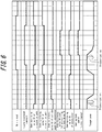
- the preform P is first fed to the open mold 1 with the preform feeding unit, and the mold 1 is then closed, as illustrated in FIG. 1A .
- the blow nozzle 2 is lowered by operation of the blow nozzle displacement unit.
- the spout 2b enters inside the mouth tube section P3, the sealing portion 2c abuts against the upper surface and the outer circumferential surface of the mouth tube section P3, and the tip 2e of the sealing portion 2c abuts against the upper surface of the neck ring P2.
- the stretching rod 3 is lowered, and the pressurized liquid is fed into the preform P from the spout 2b to expand the preform P and mold the bottle B. Subsequently, the stretching rod 3 is raised and feeding of the liquid is stopped, and as illustrated in FIG. 3B , the blow nozzle 2 is raised and the cap C is fed to the mouth tube section B3 of the bottle B by the cap feeding unit. Furthermore, in this embodiment, the tray displacement unit 5b is operated to move the tray 5a forward to a position directly below the spout 2b. As a result, even if liquid drips from the spout 2b, liquid does not spill onto the cap C or the mold 1.
- the tray 5a is withdrawn, and the blow nozzle 2 is lowered.
- the tip 2d of the spout 2b and the tip 2e of the sealing portion 2c abut the upper surface of the adapter C2, the cap C is pushed onto the mouth tube section B3, and the cap body C1 engages with the undercut B4.
- the blow nozzle 2 is raised as illustrated in FIG. 4B , and the mold 1 is opened.
- the bottle B is then transferred by the bottle transfer unit. Since the bottle B is sealed by the cap body C1, the liquid that fills the bottle B does not spill.
- the adapter C2 is removed from the bottle B and can be reused by being mounted on a new cap body C1.
- problems such as the cap body C1 breaking or soiling can be prevented.
- the adapter C2 can be used as a gripper during transfer.
- the cap body C1 need not be provided with the function of a gripper, which offers the advantage of increasing the degree of freedom in designing the cap body C1.
- the blow molding device has been illustrated with an example in which the mold 1 and the blow nozzle 2 form one pair (a one-batch type), but a plurality of pairs are preferably provided. As a result, while blow molding is being performed with one mold 1, the cap C can be attached at another mold 1 that has finished blow molding, thereby shortening the cycle time.
- the cap body C1 may be pushed by the blow nozzle 2 directly without use of the adapter C2. Also, when fixing and holding the cap C to the mouth tube section B3, the tray 5a may be left in place after being moved forward, and the cap C may be pushed by the blow nozzle 2 via the tray 5a.
- the liquid receiving unit 5 is not essential to the blow molding process and need not be used. Furthermore, the bottle B may be molded with pressurized liquid alone, without using the stretching rod 3.
- a rotating portion may be provided on the blow nozzle 2 to be rotatable about the central axis of the blow nozzle 2 (the central axis of the spout 2b), and the cap may be fixed and held against the bottle by rotating the cap with this rotating portion.
- a blow nozzle can be used to fix and hold a cap to a bottle, thus making it possible to provide a new blow molding device that has a simpler structure than that of a conventional device including a stoppering device and that reduces the size and cost of the device.
Landscapes
- Engineering & Computer Science (AREA)
- Manufacturing & Machinery (AREA)
- Mechanical Engineering (AREA)
- Blow-Moulding Or Thermoforming Of Plastics Or The Like (AREA)
- Basic Packing Technique (AREA)
- Containers Having Bodies Formed In One Piece (AREA)
Applications Claiming Priority (2)
| Application Number | Priority Date | Filing Date | Title |
|---|---|---|---|
| JP2014156907A JP6275582B2 (ja) | 2014-07-31 | 2014-07-31 | ブロー成形装置 |
| PCT/JP2015/003782 WO2016017152A1 (fr) | 2014-07-31 | 2015-07-28 | Dispositif de moulage par soufflage |
Publications (3)
| Publication Number | Publication Date |
|---|---|
| EP3178630A1 true EP3178630A1 (fr) | 2017-06-14 |
| EP3178630A4 EP3178630A4 (fr) | 2018-03-28 |
| EP3178630B1 EP3178630B1 (fr) | 2020-12-02 |
Family
ID=55217068
Family Applications (1)
| Application Number | Title | Priority Date | Filing Date |
|---|---|---|---|
| EP15827939.8A Active EP3178630B1 (fr) | 2014-07-31 | 2015-07-28 | Dispositif de moulage par soufflage |
Country Status (5)
| Country | Link |
|---|---|
| US (1) | US10279532B2 (fr) |
| EP (1) | EP3178630B1 (fr) |
| JP (1) | JP6275582B2 (fr) |
| CN (1) | CN107073797B (fr) |
| WO (1) | WO2016017152A1 (fr) |
Families Citing this family (6)
| Publication number | Priority date | Publication date | Assignee | Title |
|---|---|---|---|---|
| JP6629647B2 (ja) | 2016-03-11 | 2020-01-15 | 株式会社吉野工業所 | 液体ブロー成形装置及び液体ブロー成形方法 |
| JP6893870B2 (ja) * | 2017-12-28 | 2021-06-23 | 株式会社吉野工業所 | 液体入り容器の製造方法 |
| JP6909170B2 (ja) | 2018-01-31 | 2021-07-28 | 株式会社吉野工業所 | ブロー成形装置 |
| CN108284579B (zh) * | 2018-04-19 | 2023-11-07 | 海盐明盛塑业有限公司 | 一种塑料瓶自动成型装置 |
| EP3990252A1 (fr) * | 2019-06-28 | 2022-05-04 | Discma AG | Récipient pour matériau réduit et système et méthode de formation associés |
| CN117464963B (zh) * | 2023-12-26 | 2024-03-22 | 佛山市三水飞马包装有限公司 | 一种吹瓶机吹瓶气体排放装置及其排放控制方法 |
Family Cites Families (10)
| Publication number | Priority date | Publication date | Assignee | Title |
|---|---|---|---|---|
| DE102005034541A1 (de) | 2005-07-23 | 2007-02-01 | Sig Technology Ltd. | Verfahren und Vorrichtung zur Blasformung von Behältern |
| US7914726B2 (en) * | 2006-04-13 | 2011-03-29 | Amcor Limited | Liquid or hydraulic blow molding |
| FR2914876B1 (fr) | 2007-04-10 | 2009-07-10 | Sidel Participations | Dispositif de moulage, par soufflage ou etirage-soufflage, de recipients en matiere thermoplastique |
| ITRM20070370A1 (it) * | 2007-07-03 | 2009-01-04 | Sipa Societa Industrializzazio | Macchina di stampaggio per soffiaggio di contenitori |
| FR2978371B1 (fr) * | 2011-07-25 | 2013-08-16 | Sidel Participations | "dispositif d'injection d'un liquide sous pression pour le formage d'un recipient comportant une chambre de travail agencee en aval de moyens de pompage" |
| JP6184660B2 (ja) * | 2012-01-31 | 2017-08-23 | 株式会社吉野工業所 | ブロー成形装置及び容器の製造方法 |
| JP5872361B2 (ja) * | 2012-03-30 | 2016-03-01 | 株式会社吉野工業所 | ブロー成形装置及び合成樹脂製容器の製造方法 |
| JP5747413B2 (ja) * | 2011-12-27 | 2015-07-15 | 株式会社吉野工業所 | 2軸延伸ブロー成形装置及び容器の製造方法 |
| EP2617650B1 (fr) * | 2012-01-17 | 2014-08-20 | Nestec S.A. | Appareil pour soufflage et remplissage d'un récipient avec supports de collecte de liquide |
| JP6333577B2 (ja) * | 2014-02-28 | 2018-05-30 | 株式会社吉野工業所 | ブロー成形装置 |
-
2014
- 2014-07-31 JP JP2014156907A patent/JP6275582B2/ja active Active
-
2015
- 2015-07-28 CN CN201580041729.6A patent/CN107073797B/zh not_active Expired - Fee Related
- 2015-07-28 US US15/500,669 patent/US10279532B2/en active Active
- 2015-07-28 EP EP15827939.8A patent/EP3178630B1/fr active Active
- 2015-07-28 WO PCT/JP2015/003782 patent/WO2016017152A1/fr active Application Filing
Also Published As
| Publication number | Publication date |
|---|---|
| CN107073797B (zh) | 2019-04-26 |
| EP3178630A4 (fr) | 2018-03-28 |
| JP6275582B2 (ja) | 2018-02-07 |
| CN107073797A (zh) | 2017-08-18 |
| US10279532B2 (en) | 2019-05-07 |
| EP3178630B1 (fr) | 2020-12-02 |
| JP2016032922A (ja) | 2016-03-10 |
| WO2016017152A1 (fr) | 2016-02-04 |
| US20170217077A1 (en) | 2017-08-03 |
Similar Documents
| Publication | Publication Date | Title |
|---|---|---|
| EP3175969B1 (fr) | Dispositif de moulage par soufflage | |
| EP3178630A1 (fr) | Dispositif de moulage par soufflage | |
| EP3269530B1 (fr) | Dispositif de moulage par soufflage | |
| EP3479994B1 (fr) | Dispositif de moulage par soufflage de liquide | |
| EP3647017B1 (fr) | Méthode de fabrication d'un récipient rempli de liquide | |
| JP6450617B2 (ja) | ブロー成形装置 | |
| JP2016168800A (ja) | ブロー成形装置 | |
| US10556373B2 (en) | Container production method by liquid blow molding | |
| EP3533585B1 (fr) | Dispositif de moulage par soufflage d'un liquide | |
| JP6457055B2 (ja) | ブロー成形装置 | |
| EP3978222B1 (fr) | Dispositif de moulage par soufflage | |
| EP3488992B1 (fr) | Procédé de production d'un récipient par moulage par soufflage de liquide | |
| EP3150356B1 (fr) | Procédé de fabrication de récipient composite, matrice de moulage et récipient composite | |
| EP3488991B1 (fr) | Procédé de production d'un récipient par moulage par soufflage de liquide | |
| CN109311215A (zh) | 利用液体吹塑成形的容器制造方法 | |
| EP3888882A1 (fr) | Dispositif de moulage par soufflage |
Legal Events
| Date | Code | Title | Description |
|---|---|---|---|
| STAA | Information on the status of an ep patent application or granted ep patent |
Free format text: STATUS: THE INTERNATIONAL PUBLICATION HAS BEEN MADE |
|
| PUAI | Public reference made under article 153(3) epc to a published international application that has entered the european phase |
Free format text: ORIGINAL CODE: 0009012 |
|
| STAA | Information on the status of an ep patent application or granted ep patent |
Free format text: STATUS: REQUEST FOR EXAMINATION WAS MADE |
|
| 17P | Request for examination filed |
Effective date: 20170228 |
|
| AK | Designated contracting states |
Kind code of ref document: A1 Designated state(s): AL AT BE BG CH CY CZ DE DK EE ES FI FR GB GR HR HU IE IS IT LI LT LU LV MC MK MT NL NO PL PT RO RS SE SI SK SM TR |
|
| AX | Request for extension of the european patent |
Extension state: BA ME |
|
| XX | Miscellaneous (additional remarks) |
Free format text: THE APPLICANT HAS FILED A REQUEST PURSUANT TO ARTICLE 14(2) EPC TO BRING THE TRANSLATION INTO CONFORMITY WITH THE ORIGINAL TEXT OF THE APPLICATION. |
|
| DAV | Request for validation of the european patent (deleted) | ||
| DAX | Request for extension of the european patent (deleted) | ||
| A4 | Supplementary search report drawn up and despatched |
Effective date: 20180227 |
|
| RIC1 | Information provided on ipc code assigned before grant |
Ipc: B29C 49/42 20060101ALI20180221BHEP Ipc: B29L 31/00 20060101ALN20180221BHEP Ipc: B29C 49/46 20060101AFI20180221BHEP Ipc: B29C 49/58 20060101ALI20180221BHEP Ipc: B67C 3/02 20060101ALI20180221BHEP Ipc: B29L 22/00 20060101ALI20180221BHEP Ipc: B29K 67/00 20060101ALN20180221BHEP Ipc: B29C 49/08 20060101ALI20180221BHEP Ipc: B29C 49/12 20060101ALI20180221BHEP Ipc: B29K 23/00 20060101ALN20180221BHEP |
|
| RAP1 | Party data changed (applicant data changed or rights of an application transferred) |
Owner name: DISCMA AG |
|
| GRAP | Despatch of communication of intention to grant a patent |
Free format text: ORIGINAL CODE: EPIDOSNIGR1 |
|
| STAA | Information on the status of an ep patent application or granted ep patent |
Free format text: STATUS: GRANT OF PATENT IS INTENDED |
|
| RIC1 | Information provided on ipc code assigned before grant |
Ipc: B29L 22/00 20060101ALI20200622BHEP Ipc: B29L 31/00 20060101ALN20200622BHEP Ipc: B29C 49/46 20060101AFI20200622BHEP Ipc: B29K 23/00 20060101ALN20200622BHEP Ipc: B67C 3/02 20060101ALI20200622BHEP Ipc: B29K 67/00 20060101ALN20200622BHEP Ipc: B29C 49/42 20060101ALI20200622BHEP Ipc: B29C 49/58 20060101ALI20200622BHEP Ipc: B29C 49/08 20060101ALI20200622BHEP Ipc: B29C 49/12 20060101ALI20200622BHEP |
|
| INTG | Intention to grant announced |
Effective date: 20200715 |
|
| GRAS | Grant fee paid |
Free format text: ORIGINAL CODE: EPIDOSNIGR3 |
|
| GRAA | (expected) grant |
Free format text: ORIGINAL CODE: 0009210 |
|
| STAA | Information on the status of an ep patent application or granted ep patent |
Free format text: STATUS: THE PATENT HAS BEEN GRANTED |
|
| AK | Designated contracting states |
Kind code of ref document: B1 Designated state(s): AL AT BE BG CH CY CZ DE DK EE ES FI FR GB GR HR HU IE IS IT LI LT LU LV MC MK MT NL NO PL PT RO RS SE SI SK SM TR |
|
| REG | Reference to a national code |
Ref country code: GB Ref legal event code: FG4D |
|
| XX | Miscellaneous (additional remarks) |
Free format text: THE APPLICANT HAS FILED A REQUEST PURSUANT TO ARTICLE 14(2) EPC TO BRING THE TRANSLATION INTO CONFORMITY WITH THE ORIGINAL TEXT OF THE APPLICATION. |
|
| REG | Reference to a national code |
Ref country code: AT Ref legal event code: REF Ref document number: 1340420 Country of ref document: AT Kind code of ref document: T Effective date: 20201215 Ref country code: CH Ref legal event code: NV Representative=s name: MICHELI AND CIE SA, CH Ref country code: CH Ref legal event code: EP |
|
| REG | Reference to a national code |
Ref country code: DE Ref legal event code: R096 Ref document number: 602015063004 Country of ref document: DE |
|
| REG | Reference to a national code |
Ref country code: IE Ref legal event code: FG4D |
|
| PG25 | Lapsed in a contracting state [announced via postgrant information from national office to epo] |
Ref country code: NO Free format text: LAPSE BECAUSE OF FAILURE TO SUBMIT A TRANSLATION OF THE DESCRIPTION OR TO PAY THE FEE WITHIN THE PRESCRIBED TIME-LIMIT Effective date: 20210302 Ref country code: RS Free format text: LAPSE BECAUSE OF FAILURE TO SUBMIT A TRANSLATION OF THE DESCRIPTION OR TO PAY THE FEE WITHIN THE PRESCRIBED TIME-LIMIT Effective date: 20201202 Ref country code: FI Free format text: LAPSE BECAUSE OF FAILURE TO SUBMIT A TRANSLATION OF THE DESCRIPTION OR TO PAY THE FEE WITHIN THE PRESCRIBED TIME-LIMIT Effective date: 20201202 Ref country code: GR Free format text: LAPSE BECAUSE OF FAILURE TO SUBMIT A TRANSLATION OF THE DESCRIPTION OR TO PAY THE FEE WITHIN THE PRESCRIBED TIME-LIMIT Effective date: 20210303 |
|
| REG | Reference to a national code |
Ref country code: NL Ref legal event code: MP Effective date: 20201202 |
|
| REG | Reference to a national code |
Ref country code: AT Ref legal event code: MK05 Ref document number: 1340420 Country of ref document: AT Kind code of ref document: T Effective date: 20201202 |
|
| PG25 | Lapsed in a contracting state [announced via postgrant information from national office to epo] |
Ref country code: BG Free format text: LAPSE BECAUSE OF FAILURE TO SUBMIT A TRANSLATION OF THE DESCRIPTION OR TO PAY THE FEE WITHIN THE PRESCRIBED TIME-LIMIT Effective date: 20210302 Ref country code: SE Free format text: LAPSE BECAUSE OF FAILURE TO SUBMIT A TRANSLATION OF THE DESCRIPTION OR TO PAY THE FEE WITHIN THE PRESCRIBED TIME-LIMIT Effective date: 20201202 Ref country code: PL Free format text: LAPSE BECAUSE OF FAILURE TO SUBMIT A TRANSLATION OF THE DESCRIPTION OR TO PAY THE FEE WITHIN THE PRESCRIBED TIME-LIMIT Effective date: 20201202 Ref country code: LV Free format text: LAPSE BECAUSE OF FAILURE TO SUBMIT A TRANSLATION OF THE DESCRIPTION OR TO PAY THE FEE WITHIN THE PRESCRIBED TIME-LIMIT Effective date: 20201202 |
|
| PG25 | Lapsed in a contracting state [announced via postgrant information from national office to epo] |
Ref country code: NL Free format text: LAPSE BECAUSE OF FAILURE TO SUBMIT A TRANSLATION OF THE DESCRIPTION OR TO PAY THE FEE WITHIN THE PRESCRIBED TIME-LIMIT Effective date: 20201202 Ref country code: HR Free format text: LAPSE BECAUSE OF FAILURE TO SUBMIT A TRANSLATION OF THE DESCRIPTION OR TO PAY THE FEE WITHIN THE PRESCRIBED TIME-LIMIT Effective date: 20201202 |
|
| REG | Reference to a national code |
Ref country code: LT Ref legal event code: MG9D |
|
| PG25 | Lapsed in a contracting state [announced via postgrant information from national office to epo] |
Ref country code: RO Free format text: LAPSE BECAUSE OF FAILURE TO SUBMIT A TRANSLATION OF THE DESCRIPTION OR TO PAY THE FEE WITHIN THE PRESCRIBED TIME-LIMIT Effective date: 20201202 Ref country code: PT Free format text: LAPSE BECAUSE OF FAILURE TO SUBMIT A TRANSLATION OF THE DESCRIPTION OR TO PAY THE FEE WITHIN THE PRESCRIBED TIME-LIMIT Effective date: 20210405 Ref country code: SK Free format text: LAPSE BECAUSE OF FAILURE TO SUBMIT A TRANSLATION OF THE DESCRIPTION OR TO PAY THE FEE WITHIN THE PRESCRIBED TIME-LIMIT Effective date: 20201202 Ref country code: LT Free format text: LAPSE BECAUSE OF FAILURE TO SUBMIT A TRANSLATION OF THE DESCRIPTION OR TO PAY THE FEE WITHIN THE PRESCRIBED TIME-LIMIT Effective date: 20201202 Ref country code: SM Free format text: LAPSE BECAUSE OF FAILURE TO SUBMIT A TRANSLATION OF THE DESCRIPTION OR TO PAY THE FEE WITHIN THE PRESCRIBED TIME-LIMIT Effective date: 20201202 Ref country code: EE Free format text: LAPSE BECAUSE OF FAILURE TO SUBMIT A TRANSLATION OF THE DESCRIPTION OR TO PAY THE FEE WITHIN THE PRESCRIBED TIME-LIMIT Effective date: 20201202 Ref country code: CZ Free format text: LAPSE BECAUSE OF FAILURE TO SUBMIT A TRANSLATION OF THE DESCRIPTION OR TO PAY THE FEE WITHIN THE PRESCRIBED TIME-LIMIT Effective date: 20201202 |
|
| PG25 | Lapsed in a contracting state [announced via postgrant information from national office to epo] |
Ref country code: AT Free format text: LAPSE BECAUSE OF FAILURE TO SUBMIT A TRANSLATION OF THE DESCRIPTION OR TO PAY THE FEE WITHIN THE PRESCRIBED TIME-LIMIT Effective date: 20201202 |
|
| REG | Reference to a national code |
Ref country code: DE Ref legal event code: R097 Ref document number: 602015063004 Country of ref document: DE |
|
| PG25 | Lapsed in a contracting state [announced via postgrant information from national office to epo] |
Ref country code: IS Free format text: LAPSE BECAUSE OF FAILURE TO SUBMIT A TRANSLATION OF THE DESCRIPTION OR TO PAY THE FEE WITHIN THE PRESCRIBED TIME-LIMIT Effective date: 20210402 |
|
| PLBE | No opposition filed within time limit |
Free format text: ORIGINAL CODE: 0009261 |
|
| STAA | Information on the status of an ep patent application or granted ep patent |
Free format text: STATUS: NO OPPOSITION FILED WITHIN TIME LIMIT |
|
| PG25 | Lapsed in a contracting state [announced via postgrant information from national office to epo] |
Ref country code: AL Free format text: LAPSE BECAUSE OF FAILURE TO SUBMIT A TRANSLATION OF THE DESCRIPTION OR TO PAY THE FEE WITHIN THE PRESCRIBED TIME-LIMIT Effective date: 20201202 |
|
| 26N | No opposition filed |
Effective date: 20210903 |
|
| PG25 | Lapsed in a contracting state [announced via postgrant information from national office to epo] |
Ref country code: SI Free format text: LAPSE BECAUSE OF FAILURE TO SUBMIT A TRANSLATION OF THE DESCRIPTION OR TO PAY THE FEE WITHIN THE PRESCRIBED TIME-LIMIT Effective date: 20201202 Ref country code: DK Free format text: LAPSE BECAUSE OF FAILURE TO SUBMIT A TRANSLATION OF THE DESCRIPTION OR TO PAY THE FEE WITHIN THE PRESCRIBED TIME-LIMIT Effective date: 20201202 |
|
| PG25 | Lapsed in a contracting state [announced via postgrant information from national office to epo] |
Ref country code: ES Free format text: LAPSE BECAUSE OF FAILURE TO SUBMIT A TRANSLATION OF THE DESCRIPTION OR TO PAY THE FEE WITHIN THE PRESCRIBED TIME-LIMIT Effective date: 20201202 |
|
| GBPC | Gb: european patent ceased through non-payment of renewal fee |
Effective date: 20210728 |
|
| PG25 | Lapsed in a contracting state [announced via postgrant information from national office to epo] |
Ref country code: MC Free format text: LAPSE BECAUSE OF FAILURE TO SUBMIT A TRANSLATION OF THE DESCRIPTION OR TO PAY THE FEE WITHIN THE PRESCRIBED TIME-LIMIT Effective date: 20201202 |
|
| REG | Reference to a national code |
Ref country code: BE Ref legal event code: MM Effective date: 20210731 |
|
| PG25 | Lapsed in a contracting state [announced via postgrant information from national office to epo] |
Ref country code: GB Free format text: LAPSE BECAUSE OF NON-PAYMENT OF DUE FEES Effective date: 20210728 |
|
| PG25 | Lapsed in a contracting state [announced via postgrant information from national office to epo] |
Ref country code: IS Free format text: LAPSE BECAUSE OF FAILURE TO SUBMIT A TRANSLATION OF THE DESCRIPTION OR TO PAY THE FEE WITHIN THE PRESCRIBED TIME-LIMIT Effective date: 20210402 Ref country code: LU Free format text: LAPSE BECAUSE OF NON-PAYMENT OF DUE FEES Effective date: 20210728 |
|
| PG25 | Lapsed in a contracting state [announced via postgrant information from national office to epo] |
Ref country code: IE Free format text: LAPSE BECAUSE OF NON-PAYMENT OF DUE FEES Effective date: 20210728 Ref country code: BE Free format text: LAPSE BECAUSE OF NON-PAYMENT OF DUE FEES Effective date: 20210731 |
|
| PG25 | Lapsed in a contracting state [announced via postgrant information from national office to epo] |
Ref country code: HU Free format text: LAPSE BECAUSE OF FAILURE TO SUBMIT A TRANSLATION OF THE DESCRIPTION OR TO PAY THE FEE WITHIN THE PRESCRIBED TIME-LIMIT; INVALID AB INITIO Effective date: 20150728 |
|
| P01 | Opt-out of the competence of the unified patent court (upc) registered |
Effective date: 20230524 |
|
| PG25 | Lapsed in a contracting state [announced via postgrant information from national office to epo] |
Ref country code: CY Free format text: LAPSE BECAUSE OF FAILURE TO SUBMIT A TRANSLATION OF THE DESCRIPTION OR TO PAY THE FEE WITHIN THE PRESCRIBED TIME-LIMIT Effective date: 20201202 |
|
| PGFP | Annual fee paid to national office [announced via postgrant information from national office to epo] |
Ref country code: IT Payment date: 20230620 Year of fee payment: 9 Ref country code: FR Payment date: 20230621 Year of fee payment: 9 |
|
| PGFP | Annual fee paid to national office [announced via postgrant information from national office to epo] |
Ref country code: CH Payment date: 20230801 Year of fee payment: 9 |
|
| PGFP | Annual fee paid to national office [announced via postgrant information from national office to epo] |
Ref country code: DE Payment date: 20230620 Year of fee payment: 9 |
|
| PG25 | Lapsed in a contracting state [announced via postgrant information from national office to epo] |
Ref country code: MK Free format text: LAPSE BECAUSE OF FAILURE TO SUBMIT A TRANSLATION OF THE DESCRIPTION OR TO PAY THE FEE WITHIN THE PRESCRIBED TIME-LIMIT Effective date: 20201202 |