EP3178599B1 - Ständermaschine - Google Patents
Ständermaschine Download PDFInfo
- Publication number
- EP3178599B1 EP3178599B1 EP16202184.4A EP16202184A EP3178599B1 EP 3178599 B1 EP3178599 B1 EP 3178599B1 EP 16202184 A EP16202184 A EP 16202184A EP 3178599 B1 EP3178599 B1 EP 3178599B1
- Authority
- EP
- European Patent Office
- Prior art keywords
- stand
- linear drive
- solid state
- machine
- accordance
- Prior art date
- Legal status (The legal status is an assumption and is not a legal conclusion. Google has not performed a legal analysis and makes no representation as to the accuracy of the status listed.)
- Active
Links
Images

Classifications
-
- B—PERFORMING OPERATIONS; TRANSPORTING
- B23—MACHINE TOOLS; METAL-WORKING NOT OTHERWISE PROVIDED FOR
- B23K—SOLDERING OR UNSOLDERING; WELDING; CLADDING OR PLATING BY SOLDERING OR WELDING; CUTTING BY APPLYING HEAT LOCALLY, e.g. FLAME CUTTING; WORKING BY LASER BEAM
- B23K20/00—Non-electric welding by applying impact or other pressure, with or without the application of heat, e.g. cladding or plating
- B23K20/10—Non-electric welding by applying impact or other pressure, with or without the application of heat, e.g. cladding or plating making use of vibrations, e.g. ultrasonic welding
-
- B—PERFORMING OPERATIONS; TRANSPORTING
- B23—MACHINE TOOLS; METAL-WORKING NOT OTHERWISE PROVIDED FOR
- B23K—SOLDERING OR UNSOLDERING; WELDING; CLADDING OR PLATING BY SOLDERING OR WELDING; CUTTING BY APPLYING HEAT LOCALLY, e.g. FLAME CUTTING; WORKING BY LASER BEAM
- B23K20/00—Non-electric welding by applying impact or other pressure, with or without the application of heat, e.g. cladding or plating
- B23K20/26—Auxiliary equipment
-
- B—PERFORMING OPERATIONS; TRANSPORTING
- B23—MACHINE TOOLS; METAL-WORKING NOT OTHERWISE PROVIDED FOR
- B23K—SOLDERING OR UNSOLDERING; WELDING; CLADDING OR PLATING BY SOLDERING OR WELDING; CUTTING BY APPLYING HEAT LOCALLY, e.g. FLAME CUTTING; WORKING BY LASER BEAM
- B23K37/00—Auxiliary devices or processes, not specially adapted for a procedure covered by only one of the other main groups of this subclass
- B23K37/02—Carriages for supporting the welding or cutting element
- B23K37/0211—Carriages for supporting the welding or cutting element travelling on a guide member, e.g. rail, track
Definitions
- the present invention relates to a column machine such as a column or column drilling machine and in particular an ultrasonic welding machine according to the preamble of claim 1, such as from US Pat EP 2 905 108 A1 known.
- Such stand machines can comprise a base plate for receiving a workpiece to be machined by means of the machine tool, to which a stand is rigidly connected, along which the working element is displaceably guided.
- a slide can be provided which is guided displaceably along the longitudinal direction of the stator and carries a vibration generator by means of which a sonotrode serving as a working element can be excited to high-frequency vibrations. If the slide is moved in the longitudinal direction by means of the linear drive until the sonotrode comes into contact with the workpiece to be welded, a desired welding force can be applied to the workpiece by means of the linear drive via the sonotrode, which must be set to a certain size depending on the application. for which purpose a correspondingly designed force control can be provided.
- the invention is therefore based on the object of specifying a column machine, via the working element of which a force of predetermined magnitude can be applied as precisely as possible to a workpiece to be machined, even if the workpiece is relatively rigid or rigid.
- a column machine in particular an ultrasonic welding machine, with the features of claim 1 and above all in that the vibration generator is in alignment with the travel of the linear drive and that an elastically deformable body is in the force flow path between the working element and the column Form of a solid body joint is provided, which is subject to elastic deformation as a result of a force that can be applied to a workpiece that can be positioned on a base plate with the aid of the linear drive via the working element.
- the vibration generator and thus also the working element are in alignment with the travel of the linear drive ensures that it closes as a result of a force that is applied to a workpiece that can be positioned on a base plate with the aid of the linear drive via the working element there is no uncontrolled bending deformation in the area of the linear drive and / or the vibration generator, the size of which is difficult to estimate.
- the elastically deformable solid-state joint deliberately allows the linear drive to continue its stroke movement within certain limits from the point in time at which the working element comes into contact with the workpiece, so that the stroke movement that occurs from this point in time on the workpiece to be able to determine the applied force for control purposes.
- the machine tool and in particular the components of the same guided along the stator are therefore not subject to any uncontrollable and unpredictable deformations, since due to the position of the vibration generator in the alignment of the adjustment path of the linear drive, only deformations of the elastically deformable solid-state joint are permitted if a Force is applied to the workpiece to be machined. Since the elastically deformable solid-state joint can be specifically designed in order to experience such deformations, the force applied to the workpiece can be precisely determined and regulated on the basis of the stroke movement forced in this way.
- the elastically deformable solid body joint is located in the force flow path between the linear drive and the stator.
- the solid-state joint can be attached to the stand as a carrier for the linear drive in order to carry the linear drive including the components of the welding machine that can be moved by it, such as the slide including the vibration generator and working element.
- the elastically deformable solid-state joint can be a cantilever beam attached to the stand, at the free end of which the linear drive is attached.
- the solid body joint comprises a fastening section attached to the stand and a support section on which the linear drive is provided, the support section being elastically coupled to the fastening section in such a way that the support section as a result of a force that is generated with the aid of the linear drive can be applied via a working element to a workpiece that can be positioned on the base plate, yields essentially rotation-free in the longitudinal direction of the stand.
- the fastening section can be connected to the support section via a shear-elastic solid body, one or more vertically standing perforated plates or one or more frames which transfer an introduced transverse force load essentially without bending, so that the support section attached to it does not twist.
- the elastically deformable solid-state joint can, according to another embodiment, be formed, for example, by a self-contained frame.
- the solid-state joint can be formed in that the fastening section attached to the stand and the support section carrying the linear drive are coupled to one another via at least two bending beams offset from one another in the longitudinal direction of the stand, which are rigidly connected to the fastening section and the support section and are preferably made in one piece or made of the same material are executed with this.
- the support section can comprise two support plates offset from one another transversely to the longitudinal direction of the stand, each support plate being coupled to the fastening section via at least two bending bars offset from one another in the longitudinal direction of the stand, which are rigidly connected to the fastening section and the respective support plate and preferably in one piece or are made of the same material as this.
- a stop can be provided according to a further embodiment , which limits the elastic deformation of the elastically deformable solid-state joint as a result of a force that can be applied to a workpiece that can be positioned on a base plate with the aid of the linear drive via a work element, to a maximum value of, for example, about 1 mm or less.
- Such an end stop can prevent excessive deformation of the solid-state joint in the event of a malfunction, particularly with high forces that have to be applied to the workpiece, which would otherwise be at the expense of the machining precision of the machine tool.
- the stop can be formed by a contact surface on the support section and a stationary counter surface on which the contact surface in the event of an elastic deformation of the solid-state joint.
- the stop on the elastically deformable solid body joint can be formed between two bending bars offset from one another in the longitudinal direction of the stator, for example in the form of a step, a groove or a notch that can come into contact with a counter-step as a counter-contact surface that is integral with the Mounting portion is formed.
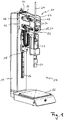
- the ultrasonic welding machine 10 has a base plate 12 on which a workpiece (not shown) to be welded can be arranged and which is rigidly connected to an upright stand 14. Along the longitudinal direction of the stand 14, a guide rail 16 is attached to the stand 14, along which a frame-like slide 18 is displaceably guided, which carries a vibration generator 21, with which a sonotrode 20 serving as a working element can be excited to high-frequency vibrations.
- a linear drive 22 in the form of a spindle drive is provided, the threaded spindle 24 of which is attached to the frame-like slide 14 in an upright position so that the vibration generator is positioned 21 in alignment with the travel of the linear drive 22, ie in the spindle axis.
- the linear drive 22 and in particular its spindle nut 28 is carried in the embodiment shown here in the manner according to the invention on a frame-like, elastically deformable solid-state joint made of steel, denoted in its entirety by the reference numeral 40, which in turn is freely cantilevered at the free end of the stand 14 .
- a servomotor 26 is provided for actuating the linear drive 22, the output gear 34 of which drives the spindle nut 28 via a ribbed belt 29, for which purpose it is provided with external toothing 30 along its circumference.
- the slide 18 including the vibration generator 21 and sonotrode 20 is thereby lowered until the sonotrode 20 comes into contact with a workpiece located on the base plate 12, whereby the linear drive 22 over the sonotrode 20 a welding force can be applied to the workpiece located on the base plate 12 in the desired manner, which, in particular when the workpiece is relatively rigid or inflexible, results in the frame-like solid-state joint 40 undergoing an elastic deformation in the desired manner.
- the vibration generator 21 together with its sonotrode 20 is in alignment with the travel of the linear drive 22, apart from this elastic deformation of the elastically deformable solid-state joint 40, no or only slight deformations occur in the force flow path between the sonotrode 20 and the stator 14. Since the working element 20 is also in alignment with the travel range of the linear drive 22, it is ensured that no uncontrolled bending deformations occur as a result of a force which is applied to a workpiece that can be positioned on the base plate 12 with the aid of the linear drive 22 via the working element 20 comes in the area of the linear drive 22 and / or the vibration generator 21.
- the solid-state joint 40 deliberately allows the linear drive 22 to continue its stroke movement within certain limits from the point in time at which the working element 20 comes into contact with the workpiece, in order to use the stroke movement that occurs from this point in time onwards To be able to regulate the force applied to the workpiece without overshooting.
- the elastically deformable solid body joint 40 consists essentially of two frame-like plates 42 spaced parallel to one another, which are fastened by means of suitable fastening means 43 to a plate 44 attached flat to the free end of the stand 14.
- the two plates 42 are connected to one another via two vertically spaced connecting plates 36 with the aid of suitable fastening means 37, each of which has an opening 38 through which the spindle 24 of the linear drive 22 extends.
- the spindle nut 28 of the linear drive 23 is rotatably suspended so that the weight of the linear drive 22 and the vibration generator 21 attached to it as well as that by means of the linear drive 22 are supported by the lower of the two plates 42 of the solid-state joint 40 a welding force that can be applied to a tool can be transmitted to the stand 14.
- the two plates 42 are kept at a distance by the plate 44 attached to the stand 14 and the two connecting plates 36, as a result of which a space for receiving the linear drive 22 is created between the two plates 42 is, which also serves to accommodate the servomotor 26 by which the linear drive 22 is driven.
- Each of the two plates 42 of the solid-state joint 40 has a substantially frame-like shape.
- This frame shape is essentially due to the fact that each plate 42 has a fastening section 46 attached to the stand 14 or to the plate 44 attached to it and a support section 48 to which the linear drive 22 is attached via the lower connecting plate 36, the The fastening section 46 and the support section 48 are coupled to one another via two bending bars 50 offset from one another in the longitudinal direction of the stand 14, as a result of which the two plates 42 have a frame-like, continuous, closed shape.
- the support sections 48 of the two plates 42 can also be referred to as support plates and the attachment sections 46 as attachment plates.
- the bending bars 50 are rigidly connected to the fastening section 46 and to the support section 48 via arm sections 49 with a larger cross-section than the bending bars 50, the arm sections 49 and the bending bars 50 being made of the same plate material as the fastening section 46 and the support section 48 are made.
- the frame-like shape of the plates 42 can be created in that one or more through openings 54 are created in a substantially rectangular plate, which are delimited or bordered by the bending beams 50, the fastening section 46 and the support section 48, among other things.
- the two frame-like plates 42 of the solid-state joint 40 force a shear of the solid-state joint 40 under load and thus form a parallel guide that only allows vertical deformation when a force is applied to a workpiece via the linear drive 22 becomes.
- a twisting or tilting of the linear drive 22 and thus also of the working member 20 is prevented, since a parallel displacement of the support section 48 and thus the linear drive 22 is forced by the two parallel-connected bending beams 15.
- the solid body joint is therefore a joint insofar as it enables a relative movement of two bodies, which are coupled to one another by the solid body joint, like a sliding joint.
- a freely projecting bolt 52 extends from the fastening section 46 of the two plates 42, separating the two through openings 54 from one another and forming a pin 56 at its free end which engages in a corresponding recess 58 on the edge of the support section 48, however, in the vertical direction between the recess 58 and the pin 56 there is a play of a few mm, for example about 1 mm, in order to achieve the desired elastic deformation of the solid-state joint 40 to allow, but to prevent plastic deformation of the same.
- the elastically deformable solid body joint 40 thus has a stop which is formed by a contact surface in the form of the recess 58 on the support section 48 and a counter contact surface in the form of the pin 56, since the contact surface of the recess 58 abuts the corresponding counter contact surface of the pin 56, when the force applied to the workpiece to be machined exceeds a certain value.
- the bolt 52 can be omitted, whereby the frame-like shape of the two plates 42 becomes more apparent.
- the frame-like shape of the plates 42 can be produced in that a single through-opening 54 is created in a substantially rectangular plate, which is then limited or bordered by the bending beam 50, the fastening section 46 and the support section 48.
Landscapes
- Engineering & Computer Science (AREA)
- Mechanical Engineering (AREA)
- Physics & Mathematics (AREA)
- Optics & Photonics (AREA)
- Pressure Welding/Diffusion-Bonding (AREA)
- Bending Of Plates, Rods, And Pipes (AREA)
- Machine Tool Units (AREA)
- Lining Or Joining Of Plastics Or The Like (AREA)
- Linear Motors (AREA)
- Manufacture Of Motors, Generators (AREA)
Priority Applications (2)
| Application Number | Priority Date | Filing Date | Title |
|---|---|---|---|
| PL16202184T PL3178599T3 (pl) | 2015-12-08 | 2016-12-05 | Obrabiarka stojakowa |
| SI201630991T SI3178599T1 (sl) | 2015-12-08 | 2016-12-05 | Stebrni stroj |
Applications Claiming Priority (1)
| Application Number | Priority Date | Filing Date | Title |
|---|---|---|---|
| DE102015121354.0A DE102015121354A1 (de) | 2015-12-08 | 2015-12-08 | Ständermaschine |
Publications (3)
| Publication Number | Publication Date |
|---|---|
| EP3178599A2 EP3178599A2 (de) | 2017-06-14 |
| EP3178599A3 EP3178599A3 (de) | 2017-08-30 |
| EP3178599B1 true EP3178599B1 (de) | 2020-09-16 |
Family
ID=57482317
Family Applications (1)
| Application Number | Title | Priority Date | Filing Date |
|---|---|---|---|
| EP16202184.4A Active EP3178599B1 (de) | 2015-12-08 | 2016-12-05 | Ständermaschine |
Country Status (7)
| Country | Link |
|---|---|
| EP (1) | EP3178599B1 (pl) |
| DE (1) | DE102015121354A1 (pl) |
| ES (1) | ES2825748T3 (pl) |
| HU (1) | HUE051859T2 (pl) |
| PL (1) | PL3178599T3 (pl) |
| PT (1) | PT3178599T (pl) |
| SI (1) | SI3178599T1 (pl) |
Families Citing this family (1)
| Publication number | Priority date | Publication date | Assignee | Title |
|---|---|---|---|---|
| DE102017216446A1 (de) * | 2017-09-17 | 2019-03-21 | Deckel Maho Seebach Gmbh | Werkzeugmaschine zur Bearbeitung eines Werkstücks |
Family Cites Families (8)
| Publication number | Priority date | Publication date | Assignee | Title |
|---|---|---|---|---|
| DE947350C (de) * | 1940-03-22 | 1956-08-16 | Siemens Ag | Anordnung zur Herstellung von Schweissverbindungen |
| US4527727A (en) * | 1983-04-12 | 1985-07-09 | Fairchild Industries, Inc. | Stabilized ultrasonic welding apparatus |
| DE19861021B4 (de) * | 1998-03-25 | 2004-10-28 | Eduard Küsters Maschinenfabrik GmbH & Co. KG | Vorrichtung zum Bearbeiten einer Materialbahn mit Ultraschall |
| EP1235266A1 (en) * | 1999-11-30 | 2002-08-28 | Toray Engineering Co., Ltd. | Chip bonding device |
| DE10331064B4 (de) * | 2003-07-09 | 2007-10-04 | Eduard Küsters Maschinenfabrik GmbH & Co. KG | Vorrichtung zum Bearbeiten einer Materialbahn |
| US9144937B2 (en) * | 2006-05-08 | 2015-09-29 | Dukane Corporation | Ultrasonic press using servo motor with delayed motion |
| DE102009002675A1 (de) * | 2009-04-27 | 2010-10-28 | Herrmann Ultraschalltechnik Gmbh & Co. Kg | Ultraschallsiegelvorrichtung und Verfahren zum Versiegeln von Materialbahnen |
| DE102014101627A1 (de) * | 2014-02-10 | 2015-08-13 | Ms Spaichingen Gmbh | Gestell für eine Maschine |
-
2015
- 2015-12-08 DE DE102015121354.0A patent/DE102015121354A1/de not_active Withdrawn
-
2016
- 2016-12-05 ES ES16202184T patent/ES2825748T3/es active Active
- 2016-12-05 SI SI201630991T patent/SI3178599T1/sl unknown
- 2016-12-05 PL PL16202184T patent/PL3178599T3/pl unknown
- 2016-12-05 EP EP16202184.4A patent/EP3178599B1/de active Active
- 2016-12-05 HU HUE16202184A patent/HUE051859T2/hu unknown
- 2016-12-05 PT PT162021844T patent/PT3178599T/pt unknown
Non-Patent Citations (1)
| Title |
|---|
| None * |
Also Published As
| Publication number | Publication date |
|---|---|
| SI3178599T1 (sl) | 2020-12-31 |
| EP3178599A2 (de) | 2017-06-14 |
| PT3178599T (pt) | 2020-10-22 |
| PL3178599T3 (pl) | 2021-03-08 |
| HUE051859T2 (hu) | 2021-03-29 |
| EP3178599A3 (de) | 2017-08-30 |
| DE102015121354A1 (de) | 2017-06-08 |
| ES2825748T3 (es) | 2021-05-17 |
Similar Documents
| Publication | Publication Date | Title |
|---|---|---|
| DE102017107244B4 (de) | Haltevorrichtung für einen Roboter | |
| EP3074152B1 (de) | Werkzeugrüstsystem für biegepresse | |
| DE3715927C2 (pl) | ||
| DE7718218U1 (de) | Schnittwerkzeugsatz zum schneiden laenglicher werkstuecke | |
| EP4117837B1 (de) | Biegemaschine | |
| DE3642900C2 (de) | Verfahren und Vorrichtung zur Befestigung von Karosserieblechen | |
| EP2292409A1 (de) | Werkzeugträger, Werkzeug und Arbeitsstation mit Werkzeugträger und daran befestigtem Werkzeug | |
| EP2846966B1 (de) | Transferzentrum zur spanenden bearbeitung mindestens eines werkstücks, mit einem positionsausgleichssystem | |
| WO2001094048A1 (de) | Kaltwalzmaschine | |
| EP3470147B1 (de) | Hydraulisches stanzgerät | |
| EP3178599B1 (de) | Ständermaschine | |
| EP3305476B1 (de) | Manipulationsvorrichtung | |
| EP2540431B1 (de) | Abbrennstumpfschweißmaschine mit einem durch einen Servomotor angetriebenen Kurvengetriebe | |
| EP2921240B1 (de) | Werkzeug für eine Universalstanzmaschine mit einem schwimmend gelagerten Werkzeugteil sowie Universalstanzmaschine | |
| DE102004006421B4 (de) | Vorrichtung und Verfahren zum Verschweißen von Kunststoffprofilen zu einem Rahmenteil | |
| EP3197636B1 (de) | Bearbeitungsvorrichtung | |
| EP1097774B1 (de) | Einrichtung zur elektro-chemischen Bearbeitung von Metallen | |
| DE112009004839B4 (de) | Vorrichtung zur automatischen Justierung in transversaler Richtung und indazu lotrecht orientierter, longitudinaler Richtung | |
| EP3606688B1 (de) | Austauschbares werkzeug für eine werkzeugmaschine | |
| EP3251788A1 (de) | Vorrichtung zum abstützen eines zu bearbeitenden werkstücks | |
| DE102007039146A1 (de) | Schlittenführung einer Werkzeugmaschine | |
| EP1996365B1 (de) | Verfahren und vorrichtung zum verschweissen von elementen aus metallischen werkstoffen | |
| DE3433519C1 (de) | Reibschweißmaschine | |
| EP3061538B1 (de) | Abkantpresse | |
| WO2021013806A1 (de) | Werkzeug und verfahren zum bearbeiten von plattenförmigen werkstücken |
Legal Events
| Date | Code | Title | Description |
|---|---|---|---|
| PUAI | Public reference made under article 153(3) epc to a published international application that has entered the european phase |
Free format text: ORIGINAL CODE: 0009012 |
|
| STAA | Information on the status of an ep patent application or granted ep patent |
Free format text: STATUS: THE APPLICATION HAS BEEN PUBLISHED |
|
| AK | Designated contracting states |
Kind code of ref document: A2 Designated state(s): AL AT BE BG CH CY CZ DE DK EE ES FI FR GB GR HR HU IE IS IT LI LT LU LV MC MK MT NL NO PL PT RO RS SE SI SK SM TR |
|
| AX | Request for extension of the european patent |
Extension state: BA ME |
|
| PUAL | Search report despatched |
Free format text: ORIGINAL CODE: 0009013 |
|
| AK | Designated contracting states |
Kind code of ref document: A3 Designated state(s): AL AT BE BG CH CY CZ DE DK EE ES FI FR GB GR HR HU IE IS IT LI LT LU LV MC MK MT NL NO PL PT RO RS SE SI SK SM TR |
|
| AX | Request for extension of the european patent |
Extension state: BA ME |
|
| RIC1 | Information provided on ipc code assigned before grant |
Ipc: B23K 20/26 20060101ALI20170727BHEP Ipc: B23K 20/10 20060101AFI20170727BHEP Ipc: B23K 37/02 20060101ALI20170727BHEP Ipc: B23Q 1/00 20060101ALI20170727BHEP |
|
| STAA | Information on the status of an ep patent application or granted ep patent |
Free format text: STATUS: REQUEST FOR EXAMINATION WAS MADE |
|
| 17P | Request for examination filed |
Effective date: 20171023 |
|
| RBV | Designated contracting states (corrected) |
Designated state(s): AL AT BE BG CH CY CZ DE DK EE ES FI FR GB GR HR HU IE IS IT LI LT LU LV MC MK MT NL NO PL PT RO RS SE SI SK SM TR |
|
| STAA | Information on the status of an ep patent application or granted ep patent |
Free format text: STATUS: EXAMINATION IS IN PROGRESS |
|
| 17Q | First examination report despatched |
Effective date: 20191121 |
|
| GRAP | Despatch of communication of intention to grant a patent |
Free format text: ORIGINAL CODE: EPIDOSNIGR1 |
|
| STAA | Information on the status of an ep patent application or granted ep patent |
Free format text: STATUS: GRANT OF PATENT IS INTENDED |
|
| INTG | Intention to grant announced |
Effective date: 20200511 |
|
| GRAS | Grant fee paid |
Free format text: ORIGINAL CODE: EPIDOSNIGR3 |
|
| GRAA | (expected) grant |
Free format text: ORIGINAL CODE: 0009210 |
|
| STAA | Information on the status of an ep patent application or granted ep patent |
Free format text: STATUS: THE PATENT HAS BEEN GRANTED |
|
| AK | Designated contracting states |
Kind code of ref document: B1 Designated state(s): AL AT BE BG CH CY CZ DE DK EE ES FI FR GB GR HR HU IE IS IT LI LT LU LV MC MK MT NL NO PL PT RO RS SE SI SK SM TR |
|
| REG | Reference to a national code |
Ref country code: GB Ref legal event code: FG4D Free format text: NOT ENGLISH |
|
| REG | Reference to a national code |
Ref country code: CH Ref legal event code: EP Ref country code: CH Ref legal event code: NV Representative=s name: INTELLECTUAL PROPERTY SERVICES GMBH, CH |
|
| REG | Reference to a national code |
Ref country code: SE Ref legal event code: TRGR |
|
| REG | Reference to a national code |
Ref country code: DE Ref legal event code: R096 Ref document number: 502016011168 Country of ref document: DE |
|
| REG | Reference to a national code |
Ref country code: IE Ref legal event code: FG4D Free format text: LANGUAGE OF EP DOCUMENT: GERMAN |
|
| REG | Reference to a national code |
Ref country code: AT Ref legal event code: REF Ref document number: 1313705 Country of ref document: AT Kind code of ref document: T Effective date: 20201015 |
|
| REG | Reference to a national code |
Ref country code: PT Ref legal event code: SC4A Ref document number: 3178599 Country of ref document: PT Date of ref document: 20201022 Kind code of ref document: T Free format text: AVAILABILITY OF NATIONAL TRANSLATION Effective date: 20201016 |
|
| REG | Reference to a national code |
Ref country code: RO Ref legal event code: EPE |
|
| REG | Reference to a national code |
Ref country code: SK Ref legal event code: T3 Ref document number: E 35677 Country of ref document: SK |
|
| PG25 | Lapsed in a contracting state [announced via postgrant information from national office to epo] |
Ref country code: GR Free format text: LAPSE BECAUSE OF FAILURE TO SUBMIT A TRANSLATION OF THE DESCRIPTION OR TO PAY THE FEE WITHIN THE PRESCRIBED TIME-LIMIT Effective date: 20201217 Ref country code: BG Free format text: LAPSE BECAUSE OF FAILURE TO SUBMIT A TRANSLATION OF THE DESCRIPTION OR TO PAY THE FEE WITHIN THE PRESCRIBED TIME-LIMIT Effective date: 20201216 Ref country code: NO Free format text: LAPSE BECAUSE OF FAILURE TO SUBMIT A TRANSLATION OF THE DESCRIPTION OR TO PAY THE FEE WITHIN THE PRESCRIBED TIME-LIMIT Effective date: 20201216 Ref country code: FI Free format text: LAPSE BECAUSE OF FAILURE TO SUBMIT A TRANSLATION OF THE DESCRIPTION OR TO PAY THE FEE WITHIN THE PRESCRIBED TIME-LIMIT Effective date: 20200916 Ref country code: HR Free format text: LAPSE BECAUSE OF FAILURE TO SUBMIT A TRANSLATION OF THE DESCRIPTION OR TO PAY THE FEE WITHIN THE PRESCRIBED TIME-LIMIT Effective date: 20200916 |
|
| REG | Reference to a national code |
Ref country code: NL Ref legal event code: MP Effective date: 20200916 |
|
| PG25 | Lapsed in a contracting state [announced via postgrant information from national office to epo] |
Ref country code: LV Free format text: LAPSE BECAUSE OF FAILURE TO SUBMIT A TRANSLATION OF THE DESCRIPTION OR TO PAY THE FEE WITHIN THE PRESCRIBED TIME-LIMIT Effective date: 20200916 Ref country code: RS Free format text: LAPSE BECAUSE OF FAILURE TO SUBMIT A TRANSLATION OF THE DESCRIPTION OR TO PAY THE FEE WITHIN THE PRESCRIBED TIME-LIMIT Effective date: 20200916 |
|
| REG | Reference to a national code |
Ref country code: HU Ref legal event code: AG4A Ref document number: E051859 Country of ref document: HU |
|
| REG | Reference to a national code |
Ref country code: LT Ref legal event code: MG4D |
|
| PG25 | Lapsed in a contracting state [announced via postgrant information from national office to epo] |
Ref country code: LT Free format text: LAPSE BECAUSE OF FAILURE TO SUBMIT A TRANSLATION OF THE DESCRIPTION OR TO PAY THE FEE WITHIN THE PRESCRIBED TIME-LIMIT Effective date: 20200916 Ref country code: SM Free format text: LAPSE BECAUSE OF FAILURE TO SUBMIT A TRANSLATION OF THE DESCRIPTION OR TO PAY THE FEE WITHIN THE PRESCRIBED TIME-LIMIT Effective date: 20200916 Ref country code: EE Free format text: LAPSE BECAUSE OF FAILURE TO SUBMIT A TRANSLATION OF THE DESCRIPTION OR TO PAY THE FEE WITHIN THE PRESCRIBED TIME-LIMIT Effective date: 20200916 |
|
| REG | Reference to a national code |
Ref country code: ES Ref legal event code: FG2A Ref document number: 2825748 Country of ref document: ES Kind code of ref document: T3 Effective date: 20210517 |
|
| PG25 | Lapsed in a contracting state [announced via postgrant information from national office to epo] |
Ref country code: IS Free format text: LAPSE BECAUSE OF FAILURE TO SUBMIT A TRANSLATION OF THE DESCRIPTION OR TO PAY THE FEE WITHIN THE PRESCRIBED TIME-LIMIT Effective date: 20210116 Ref country code: AL Free format text: LAPSE BECAUSE OF FAILURE TO SUBMIT A TRANSLATION OF THE DESCRIPTION OR TO PAY THE FEE WITHIN THE PRESCRIBED TIME-LIMIT Effective date: 20200916 |
|
| REG | Reference to a national code |
Ref country code: DE Ref legal event code: R097 Ref document number: 502016011168 Country of ref document: DE |
|
| PLBE | No opposition filed within time limit |
Free format text: ORIGINAL CODE: 0009261 |
|
| STAA | Information on the status of an ep patent application or granted ep patent |
Free format text: STATUS: NO OPPOSITION FILED WITHIN TIME LIMIT |
|
| 26N | No opposition filed |
Effective date: 20210617 |
|
| PG25 | Lapsed in a contracting state [announced via postgrant information from national office to epo] |
Ref country code: MC Free format text: LAPSE BECAUSE OF FAILURE TO SUBMIT A TRANSLATION OF THE DESCRIPTION OR TO PAY THE FEE WITHIN THE PRESCRIBED TIME-LIMIT Effective date: 20200916 Ref country code: DK Free format text: LAPSE BECAUSE OF FAILURE TO SUBMIT A TRANSLATION OF THE DESCRIPTION OR TO PAY THE FEE WITHIN THE PRESCRIBED TIME-LIMIT Effective date: 20200916 |
|
| PG25 | Lapsed in a contracting state [announced via postgrant information from national office to epo] |
Ref country code: IE Free format text: LAPSE BECAUSE OF NON-PAYMENT OF DUE FEES Effective date: 20201205 Ref country code: LU Free format text: LAPSE BECAUSE OF NON-PAYMENT OF DUE FEES Effective date: 20201205 |
|
| PG25 | Lapsed in a contracting state [announced via postgrant information from national office to epo] |
Ref country code: MT Free format text: LAPSE BECAUSE OF FAILURE TO SUBMIT A TRANSLATION OF THE DESCRIPTION OR TO PAY THE FEE WITHIN THE PRESCRIBED TIME-LIMIT Effective date: 20200916 Ref country code: CY Free format text: LAPSE BECAUSE OF FAILURE TO SUBMIT A TRANSLATION OF THE DESCRIPTION OR TO PAY THE FEE WITHIN THE PRESCRIBED TIME-LIMIT Effective date: 20200916 |
|
| PG25 | Lapsed in a contracting state [announced via postgrant information from national office to epo] |
Ref country code: MK Free format text: LAPSE BECAUSE OF FAILURE TO SUBMIT A TRANSLATION OF THE DESCRIPTION OR TO PAY THE FEE WITHIN THE PRESCRIBED TIME-LIMIT Effective date: 20200916 |
|
| PG25 | Lapsed in a contracting state [announced via postgrant information from national office to epo] |
Ref country code: NL Free format text: LAPSE BECAUSE OF NON-PAYMENT OF DUE FEES Effective date: 20200923 |
|
| REG | Reference to a national code |
Ref country code: DE Ref legal event code: R082 Ref document number: 502016011168 Country of ref document: DE Representative=s name: QIP PATENTANWAELTE, DR. KUEHN & PARTNER MBB, DE Ref country code: DE Ref legal event code: R082 Ref document number: 502016011168 Country of ref document: DE Representative=s name: QIP PATENT & RECHT, DR. KUEHN & PARTNER MBB, DE |
|
| PGFP | Annual fee paid to national office [announced via postgrant information from national office to epo] |
Ref country code: DE Payment date: 20250226 Year of fee payment: 9 |
|
| PGFP | Annual fee paid to national office [announced via postgrant information from national office to epo] |
Ref country code: ES Payment date: 20250131 Year of fee payment: 9 |
|
| PGFP | Annual fee paid to national office [announced via postgrant information from national office to epo] |
Ref country code: CH Payment date: 20250101 Year of fee payment: 9 |
|
| PGFP | Annual fee paid to national office [announced via postgrant information from national office to epo] |
Ref country code: PT Payment date: 20251121 Year of fee payment: 10 |
|
| REG | Reference to a national code |
Ref country code: CH Ref legal event code: U11 Free format text: ST27 STATUS EVENT CODE: U-0-0-U10-U11 (AS PROVIDED BY THE NATIONAL OFFICE) Effective date: 20260101 |
|
| PGFP | Annual fee paid to national office [announced via postgrant information from national office to epo] |
Ref country code: GB Payment date: 20251223 Year of fee payment: 10 |
|
| PGFP | Annual fee paid to national office [announced via postgrant information from national office to epo] |
Ref country code: AT Payment date: 20251218 Year of fee payment: 10 |
|
| PGFP | Annual fee paid to national office [announced via postgrant information from national office to epo] |
Ref country code: IT Payment date: 20251218 Year of fee payment: 10 |
|
| PGFP | Annual fee paid to national office [announced via postgrant information from national office to epo] |
Ref country code: HU Payment date: 20251203 Year of fee payment: 10 Ref country code: FR Payment date: 20251223 Year of fee payment: 10 |
|
| PGFP | Annual fee paid to national office [announced via postgrant information from national office to epo] |
Ref country code: TR Payment date: 20251121 Year of fee payment: 10 Ref country code: BE Payment date: 20251231 Year of fee payment: 10 |
|
| PGFP | Annual fee paid to national office [announced via postgrant information from national office to epo] |
Ref country code: SE Payment date: 20251222 Year of fee payment: 10 |
|
| PGFP | Annual fee paid to national office [announced via postgrant information from national office to epo] |
Ref country code: CZ Payment date: 20251126 Year of fee payment: 10 |
|
| PGFP | Annual fee paid to national office [announced via postgrant information from national office to epo] |
Ref country code: PL Payment date: 20251125 Year of fee payment: 10 |
|
| PGFP | Annual fee paid to national office [announced via postgrant information from national office to epo] |
Ref country code: SK Payment date: 20251124 Year of fee payment: 10 Ref country code: RO Payment date: 20251202 Year of fee payment: 10 |
|
| PGFP | Annual fee paid to national office [announced via postgrant information from national office to epo] |
Ref country code: SI Payment date: 20251124 Year of fee payment: 10 |