EP3178475B1 - Méthode de fabrication d'une microstructure - Google Patents
Méthode de fabrication d'une microstructure Download PDFInfo
- Publication number
- EP3178475B1 EP3178475B1 EP16185914.5A EP16185914A EP3178475B1 EP 3178475 B1 EP3178475 B1 EP 3178475B1 EP 16185914 A EP16185914 A EP 16185914A EP 3178475 B1 EP3178475 B1 EP 3178475B1
- Authority
- EP
- European Patent Office
- Prior art keywords
- patch manufacturing
- manufacturing sheet
- process substrate
- patch
- bottom layer
- Prior art date
- Legal status (The legal status is an assumption and is not a legal conclusion. Google has not performed a legal analysis and makes no representation as to the accuracy of the status listed.)
- Active
Links
- 238000004519 manufacturing process Methods 0.000 title claims description 179
- 239000010410 layer Substances 0.000 claims description 171
- 238000000034 method Methods 0.000 claims description 151
- 230000008569 process Effects 0.000 claims description 114
- 239000000758 substrate Substances 0.000 claims description 106
- 239000000463 material Substances 0.000 claims description 54
- 239000012790 adhesive layer Substances 0.000 claims description 43
- 239000000203 mixture Substances 0.000 claims description 40
- 239000000853 adhesive Substances 0.000 claims description 8
- 230000001070 adhesive effect Effects 0.000 claims description 8
- 239000003814 drug Substances 0.000 description 38
- 239000011345 viscous material Substances 0.000 description 37
- 229940079593 drug Drugs 0.000 description 35
- 210000003491 skin Anatomy 0.000 description 24
- 238000012377 drug delivery Methods 0.000 description 10
- 239000000126 substance Substances 0.000 description 9
- 238000007664 blowing Methods 0.000 description 8
- 230000035515 penetration Effects 0.000 description 8
- 230000001112 coagulating effect Effects 0.000 description 7
- 238000010586 diagram Methods 0.000 description 7
- -1 polydimethylsiloxane Polymers 0.000 description 7
- 230000000975 bioactive effect Effects 0.000 description 6
- 229920000642 polymer Polymers 0.000 description 6
- 239000002904 solvent Substances 0.000 description 6
- 239000002998 adhesive polymer Substances 0.000 description 5
- 230000006378 damage Effects 0.000 description 5
- 239000011347 resin Substances 0.000 description 5
- 229920005989 resin Polymers 0.000 description 5
- 239000007787 solid Substances 0.000 description 5
- 235000013855 polyvinylpyrrolidone Nutrition 0.000 description 4
- 229920000036 polyvinylpyrrolidone Polymers 0.000 description 4
- 229920002134 Carboxymethyl cellulose Polymers 0.000 description 3
- RTZKZFJDLAIYFH-UHFFFAOYSA-N Diethyl ether Chemical compound CCOCC RTZKZFJDLAIYFH-UHFFFAOYSA-N 0.000 description 3
- XEKOWRVHYACXOJ-UHFFFAOYSA-N Ethyl acetate Chemical compound CCOC(C)=O XEKOWRVHYACXOJ-UHFFFAOYSA-N 0.000 description 3
- 239000004698 Polyethylene Substances 0.000 description 3
- DNIAPMSPPWPWGF-UHFFFAOYSA-N Propylene glycol Chemical compound CC(O)CO DNIAPMSPPWPWGF-UHFFFAOYSA-N 0.000 description 3
- XUIMIQQOPSSXEZ-UHFFFAOYSA-N Silicon Chemical compound [Si] XUIMIQQOPSSXEZ-UHFFFAOYSA-N 0.000 description 3
- 230000004888 barrier function Effects 0.000 description 3
- 230000008901 benefit Effects 0.000 description 3
- 239000008280 blood Substances 0.000 description 3
- 239000002775 capsule Substances 0.000 description 3
- 235000010948 carboxy methyl cellulose Nutrition 0.000 description 3
- 239000001768 carboxy methyl cellulose Substances 0.000 description 3
- 239000008112 carboxymethyl-cellulose Substances 0.000 description 3
- 230000015271 coagulation Effects 0.000 description 3
- 238000005345 coagulation Methods 0.000 description 3
- 230000008878 coupling Effects 0.000 description 3
- 238000010168 coupling process Methods 0.000 description 3
- 238000005859 coupling reaction Methods 0.000 description 3
- 238000010438 heat treatment Methods 0.000 description 3
- 238000002156 mixing Methods 0.000 description 3
- VLKZOEOYAKHREP-UHFFFAOYSA-N n-Hexane Chemical compound CCCCCC VLKZOEOYAKHREP-UHFFFAOYSA-N 0.000 description 3
- 229920000573 polyethylene Polymers 0.000 description 3
- 239000001267 polyvinylpyrrolidone Substances 0.000 description 3
- 235000018102 proteins Nutrition 0.000 description 3
- 108090000623 proteins and genes Proteins 0.000 description 3
- 102000004169 proteins and genes Human genes 0.000 description 3
- 229910052710 silicon Inorganic materials 0.000 description 3
- 239000010703 silicon Substances 0.000 description 3
- 210000000434 stratum corneum Anatomy 0.000 description 3
- XLYOFNOQVPJJNP-UHFFFAOYSA-N water Substances O XLYOFNOQVPJJNP-UHFFFAOYSA-N 0.000 description 3
- PUPZLCDOIYMWBV-UHFFFAOYSA-N (+/-)-1,3-Butanediol Chemical compound CC(O)CCO PUPZLCDOIYMWBV-UHFFFAOYSA-N 0.000 description 2
- CSCPPACGZOOCGX-UHFFFAOYSA-N Acetone Chemical compound CC(C)=O CSCPPACGZOOCGX-UHFFFAOYSA-N 0.000 description 2
- NIXOWILDQLNWCW-UHFFFAOYSA-M Acrylate Chemical compound [O-]C(=O)C=C NIXOWILDQLNWCW-UHFFFAOYSA-M 0.000 description 2
- HEDRZPFGACZZDS-UHFFFAOYSA-N Chloroform Chemical compound ClC(Cl)Cl HEDRZPFGACZZDS-UHFFFAOYSA-N 0.000 description 2
- LFQSCWFLJHTTHZ-UHFFFAOYSA-N Ethanol Chemical compound CCO LFQSCWFLJHTTHZ-UHFFFAOYSA-N 0.000 description 2
- LYCAIKOWRPUZTN-UHFFFAOYSA-N Ethylene glycol Chemical compound OCCO LYCAIKOWRPUZTN-UHFFFAOYSA-N 0.000 description 2
- 108010010803 Gelatin Proteins 0.000 description 2
- PEDCQBHIVMGVHV-UHFFFAOYSA-N Glycerine Chemical compound OCC(O)CO PEDCQBHIVMGVHV-UHFFFAOYSA-N 0.000 description 2
- CERQOIWHTDAKMF-UHFFFAOYSA-N Methacrylic acid Chemical compound CC(=C)C(O)=O CERQOIWHTDAKMF-UHFFFAOYSA-N 0.000 description 2
- 239000004793 Polystyrene Substances 0.000 description 2
- 229920002988 biodegradable polymer Polymers 0.000 description 2
- 239000004621 biodegradable polymer Substances 0.000 description 2
- 230000015572 biosynthetic process Effects 0.000 description 2
- 210000004369 blood Anatomy 0.000 description 2
- 229920002678 cellulose Polymers 0.000 description 2
- 239000001913 cellulose Substances 0.000 description 2
- 238000013270 controlled release Methods 0.000 description 2
- 229920001577 copolymer Polymers 0.000 description 2
- 239000008406 cosmetic ingredient Substances 0.000 description 2
- 230000002950 deficient Effects 0.000 description 2
- 239000004205 dimethyl polysiloxane Substances 0.000 description 2
- 230000000694 effects Effects 0.000 description 2
- 238000005530 etching Methods 0.000 description 2
- 229920000159 gelatin Polymers 0.000 description 2
- 239000008273 gelatin Substances 0.000 description 2
- 235000019322 gelatine Nutrition 0.000 description 2
- 235000011852 gelatine desserts Nutrition 0.000 description 2
- 239000011521 glass Substances 0.000 description 2
- 229920000591 gum Polymers 0.000 description 2
- 230000005660 hydrophilic surface Effects 0.000 description 2
- 238000001727 in vivo Methods 0.000 description 2
- 239000004615 ingredient Substances 0.000 description 2
- 238000002347 injection Methods 0.000 description 2
- 239000007924 injection Substances 0.000 description 2
- 239000002184 metal Substances 0.000 description 2
- 229920003052 natural elastomer Polymers 0.000 description 2
- 229920001194 natural rubber Polymers 0.000 description 2
- 239000003960 organic solvent Substances 0.000 description 2
- 238000000206 photolithography Methods 0.000 description 2
- 229920000435 poly(dimethylsiloxane) Polymers 0.000 description 2
- 229920000058 polyacrylate Polymers 0.000 description 2
- 229920002223 polystyrene Polymers 0.000 description 2
- 238000003908 quality control method Methods 0.000 description 2
- 229920003051 synthetic elastomer Polymers 0.000 description 2
- 239000005061 synthetic rubber Substances 0.000 description 2
- KKEYFWRCBNTPAC-UHFFFAOYSA-L terephthalate(2-) Chemical compound [O-]C(=O)C1=CC=C(C([O-])=O)C=C1 KKEYFWRCBNTPAC-UHFFFAOYSA-L 0.000 description 2
- KIUKXJAPPMFGSW-DNGZLQJQSA-N (2S,3S,4S,5R,6R)-6-[(2S,3R,4R,5S,6R)-3-Acetamido-2-[(2S,3S,4R,5R,6R)-6-[(2R,3R,4R,5S,6R)-3-acetamido-2,5-dihydroxy-6-(hydroxymethyl)oxan-4-yl]oxy-2-carboxy-4,5-dihydroxyoxan-3-yl]oxy-5-hydroxy-6-(hydroxymethyl)oxan-4-yl]oxy-3,4,5-trihydroxyoxane-2-carboxylic acid Chemical compound CC(=O)N[C@H]1[C@H](O)O[C@H](CO)[C@@H](O)[C@@H]1O[C@H]1[C@H](O)[C@@H](O)[C@H](O[C@H]2[C@@H]([C@@H](O[C@H]3[C@@H]([C@@H](O)[C@H](O)[C@H](O3)C(O)=O)O)[C@H](O)[C@@H](CO)O2)NC(C)=O)[C@@H](C(O)=O)O1 KIUKXJAPPMFGSW-DNGZLQJQSA-N 0.000 description 1
- LUEWUZLMQUOBSB-FSKGGBMCSA-N (2s,3s,4s,5s,6r)-2-[(2r,3s,4r,5r,6s)-6-[(2r,3s,4r,5s,6s)-4,5-dihydroxy-2-(hydroxymethyl)-6-[(2r,4r,5s,6r)-4,5,6-trihydroxy-2-(hydroxymethyl)oxan-3-yl]oxyoxan-3-yl]oxy-4,5-dihydroxy-2-(hydroxymethyl)oxan-3-yl]oxy-6-(hydroxymethyl)oxane-3,4,5-triol Chemical compound O[C@H]1[C@@H](O)[C@H](O)[C@@H](CO)O[C@H]1O[C@@H]1[C@@H](CO)O[C@@H](O[C@@H]2[C@H](O[C@@H](OC3[C@H](O[C@@H](O)[C@@H](O)[C@H]3O)CO)[C@@H](O)[C@H]2O)CO)[C@H](O)[C@H]1O LUEWUZLMQUOBSB-FSKGGBMCSA-N 0.000 description 1
- 229940058015 1,3-butylene glycol Drugs 0.000 description 1
- OWEGMIWEEQEYGQ-UHFFFAOYSA-N 100676-05-9 Natural products OC1C(O)C(O)C(CO)OC1OCC1C(O)C(O)C(O)C(OC2C(OC(O)C(O)C2O)CO)O1 OWEGMIWEEQEYGQ-UHFFFAOYSA-N 0.000 description 1
- MSWZFWKMSRAUBD-IVMDWMLBSA-N 2-amino-2-deoxy-D-glucopyranose Chemical compound N[C@H]1C(O)O[C@H](CO)[C@@H](O)[C@@H]1O MSWZFWKMSRAUBD-IVMDWMLBSA-N 0.000 description 1
- SATHPVQTSSUFFW-UHFFFAOYSA-N 4-[6-[(3,5-dihydroxy-4-methoxyoxan-2-yl)oxymethyl]-3,5-dihydroxy-4-methoxyoxan-2-yl]oxy-2-(hydroxymethyl)-6-methyloxane-3,5-diol Chemical compound OC1C(OC)C(O)COC1OCC1C(O)C(OC)C(O)C(OC2C(C(CO)OC(C)C2O)O)O1 SATHPVQTSSUFFW-UHFFFAOYSA-N 0.000 description 1
- RSWGJHLUYNHPMX-UHFFFAOYSA-N Abietic-Saeure Natural products C12CCC(C(C)C)=CC2=CCC2C1(C)CCCC2(C)C(O)=O RSWGJHLUYNHPMX-UHFFFAOYSA-N 0.000 description 1
- NIXOWILDQLNWCW-UHFFFAOYSA-N Acrylic acid Chemical compound OC(=O)C=C NIXOWILDQLNWCW-UHFFFAOYSA-N 0.000 description 1
- 244000106483 Anogeissus latifolia Species 0.000 description 1
- 235000011514 Anogeissus latifolia Nutrition 0.000 description 1
- 239000001904 Arabinogalactan Substances 0.000 description 1
- 229920000189 Arabinogalactan Polymers 0.000 description 1
- DKPFZGUDAPQIHT-UHFFFAOYSA-N Butyl acetate Natural products CCCCOC(C)=O DKPFZGUDAPQIHT-UHFFFAOYSA-N 0.000 description 1
- 229920002101 Chitin Polymers 0.000 description 1
- 229920001661 Chitosan Polymers 0.000 description 1
- 229920002558 Curdlan Polymers 0.000 description 1
- 239000001879 Curdlan Substances 0.000 description 1
- 229920002871 Dammar gum Polymers 0.000 description 1
- 239000004860 Dammar gum Substances 0.000 description 1
- 229920002307 Dextran Polymers 0.000 description 1
- 108090000790 Enzymes Proteins 0.000 description 1
- 102000004190 Enzymes Human genes 0.000 description 1
- 229920000896 Ethulose Polymers 0.000 description 1
- 239000001859 Ethyl hydroxyethyl cellulose Substances 0.000 description 1
- SNVFDPHQAOXWJZ-UHFFFAOYSA-N Furcelleran Chemical compound CCOC(=O)C1=C(C)NC(C=2C=CC=CC=2)=C(C(=O)OCC=2C=CC=CC=2)C1C#CC1=CC=CC=C1 SNVFDPHQAOXWJZ-UHFFFAOYSA-N 0.000 description 1
- 229920002148 Gellan gum Polymers 0.000 description 1
- 229920002581 Glucomannan Polymers 0.000 description 1
- 229920002907 Guar gum Polymers 0.000 description 1
- 239000001922 Gum ghatti Substances 0.000 description 1
- 229920000569 Gum karaya Polymers 0.000 description 1
- 229920000161 Locust bean gum Polymers 0.000 description 1
- GUBGYTABKSRVRQ-PICCSMPSSA-N Maltose Natural products O[C@@H]1[C@@H](O)[C@H](O)[C@@H](CO)O[C@@H]1O[C@@H]1[C@@H](CO)OC(O)[C@H](O)[C@H]1O GUBGYTABKSRVRQ-PICCSMPSSA-N 0.000 description 1
- WHNWPMSKXPGLAX-UHFFFAOYSA-N N-Vinyl-2-pyrrolidone Chemical compound C=CN1CCCC1=O WHNWPMSKXPGLAX-UHFFFAOYSA-N 0.000 description 1
- 239000004677 Nylon Substances 0.000 description 1
- 244000090599 Plantago psyllium Species 0.000 description 1
- 235000010451 Plantago psyllium Nutrition 0.000 description 1
- 239000005062 Polybutadiene Substances 0.000 description 1
- 239000002202 Polyethylene glycol Substances 0.000 description 1
- 229920002367 Polyisobutene Polymers 0.000 description 1
- 239000004743 Polypropylene Substances 0.000 description 1
- 239000004372 Polyvinyl alcohol Substances 0.000 description 1
- 239000004820 Pressure-sensitive adhesive Substances 0.000 description 1
- 239000004373 Pullulan Substances 0.000 description 1
- 229920001218 Pullulan Polymers 0.000 description 1
- KHPCPRHQVVSZAH-HUOMCSJISA-N Rosin Natural products O(C/C=C/c1ccccc1)[C@H]1[C@H](O)[C@@H](O)[C@@H](O)[C@@H](CO)O1 KHPCPRHQVVSZAH-HUOMCSJISA-N 0.000 description 1
- 229920002125 Sokalan® Polymers 0.000 description 1
- 241000934878 Sterculia Species 0.000 description 1
- 240000004584 Tamarindus indica Species 0.000 description 1
- 235000004298 Tamarindus indica Nutrition 0.000 description 1
- 229920001615 Tragacanth Polymers 0.000 description 1
- 206010052428 Wound Diseases 0.000 description 1
- 208000027418 Wounds and injury Diseases 0.000 description 1
- 238000010521 absorption reaction Methods 0.000 description 1
- 235000010489 acacia gum Nutrition 0.000 description 1
- 239000001785 acacia senegal l. willd gum Substances 0.000 description 1
- 235000010443 alginic acid Nutrition 0.000 description 1
- 239000000783 alginic acid Substances 0.000 description 1
- 229920000615 alginic acid Polymers 0.000 description 1
- 229960001126 alginic acid Drugs 0.000 description 1
- 150000004781 alginic acids Chemical class 0.000 description 1
- 229920013820 alkyl cellulose Polymers 0.000 description 1
- 238000013459 approach Methods 0.000 description 1
- 235000019312 arabinogalactan Nutrition 0.000 description 1
- 239000000305 astragalus gummifer gum Substances 0.000 description 1
- MSWZFWKMSRAUBD-UHFFFAOYSA-N beta-D-galactosamine Natural products NC1C(O)OC(CO)C(O)C1O MSWZFWKMSRAUBD-UHFFFAOYSA-N 0.000 description 1
- WQZGKKKJIJFFOK-VFUOTHLCSA-N beta-D-glucose Chemical compound OC[C@H]1O[C@@H](O)[C@H](O)[C@@H](O)[C@@H]1O WQZGKKKJIJFFOK-VFUOTHLCSA-N 0.000 description 1
- 239000000560 biocompatible material Substances 0.000 description 1
- 239000012620 biological material Substances 0.000 description 1
- 229960000074 biopharmaceutical Drugs 0.000 description 1
- 230000000740 bleeding effect Effects 0.000 description 1
- 230000000903 blocking effect Effects 0.000 description 1
- 210000001124 body fluid Anatomy 0.000 description 1
- 239000010839 body fluid Substances 0.000 description 1
- 235000019437 butane-1,3-diol Nutrition 0.000 description 1
- 229960001631 carbomer Drugs 0.000 description 1
- 125000004432 carbon atom Chemical group C* 0.000 description 1
- 235000010418 carrageenan Nutrition 0.000 description 1
- 239000000679 carrageenan Substances 0.000 description 1
- 229920001525 carrageenan Polymers 0.000 description 1
- 229940113118 carrageenan Drugs 0.000 description 1
- 239000005018 casein Substances 0.000 description 1
- BECPQYXYKAMYBN-UHFFFAOYSA-N casein, tech. Chemical compound NCCCCC(C(O)=O)N=C(O)C(CC(O)=O)N=C(O)C(CCC(O)=N)N=C(O)C(CC(C)C)N=C(O)C(CCC(O)=O)N=C(O)C(CC(O)=O)N=C(O)C(CCC(O)=O)N=C(O)C(C(C)O)N=C(O)C(CCC(O)=N)N=C(O)C(CCC(O)=N)N=C(O)C(CCC(O)=N)N=C(O)C(CCC(O)=O)N=C(O)C(CCC(O)=O)N=C(O)C(COP(O)(O)=O)N=C(O)C(CCC(O)=N)N=C(O)C(N)CC1=CC=CC=C1 BECPQYXYKAMYBN-UHFFFAOYSA-N 0.000 description 1
- 235000021240 caseins Nutrition 0.000 description 1
- 239000000919 ceramic Substances 0.000 description 1
- 239000003795 chemical substances by application Substances 0.000 description 1
- 229940045110 chitosan Drugs 0.000 description 1
- 229920006026 co-polymeric resin Polymers 0.000 description 1
- 239000002537 cosmetic Substances 0.000 description 1
- 235000019316 curdlan Nutrition 0.000 description 1
- 229940078035 curdlan Drugs 0.000 description 1
- 230000003247 decreasing effect Effects 0.000 description 1
- 230000007547 defect Effects 0.000 description 1
- 230000007850 degeneration Effects 0.000 description 1
- 239000007854 depigmenting agent Substances 0.000 description 1
- 210000004207 dermis Anatomy 0.000 description 1
- 238000001514 detection method Methods 0.000 description 1
- 238000011161 development Methods 0.000 description 1
- 230000018109 developmental process Effects 0.000 description 1
- 201000010099 disease Diseases 0.000 description 1
- 208000037265 diseases, disorders, signs and symptoms Diseases 0.000 description 1
- 239000002552 dosage form Substances 0.000 description 1
- 238000001035 drying Methods 0.000 description 1
- 229940088598 enzyme Drugs 0.000 description 1
- 210000002615 epidermis Anatomy 0.000 description 1
- 235000019326 ethyl hydroxyethyl cellulose Nutrition 0.000 description 1
- 238000002474 experimental method Methods 0.000 description 1
- 210000001035 gastrointestinal tract Anatomy 0.000 description 1
- 235000010492 gellan gum Nutrition 0.000 description 1
- 239000000216 gellan gum Substances 0.000 description 1
- 229940046240 glucomannan Drugs 0.000 description 1
- 229960002442 glucosamine Drugs 0.000 description 1
- 235000011187 glycerol Nutrition 0.000 description 1
- 235000010417 guar gum Nutrition 0.000 description 1
- 239000000665 guar gum Substances 0.000 description 1
- 229960002154 guar gum Drugs 0.000 description 1
- 235000019314 gum ghatti Nutrition 0.000 description 1
- 230000002440 hepatic effect Effects 0.000 description 1
- FUZZWVXGSFPDMH-UHFFFAOYSA-N hexanoic acid Chemical compound CCCCCC(O)=O FUZZWVXGSFPDMH-UHFFFAOYSA-N 0.000 description 1
- 239000005556 hormone Substances 0.000 description 1
- 229940088597 hormone Drugs 0.000 description 1
- 229920002674 hyaluronan Polymers 0.000 description 1
- 229960003160 hyaluronic acid Drugs 0.000 description 1
- 229920001477 hydrophilic polymer Polymers 0.000 description 1
- 229920013821 hydroxy alkyl cellulose Polymers 0.000 description 1
- WGCNASOHLSPBMP-UHFFFAOYSA-N hydroxyacetaldehyde Natural products OCC=O WGCNASOHLSPBMP-UHFFFAOYSA-N 0.000 description 1
- 235000010979 hydroxypropyl methyl cellulose Nutrition 0.000 description 1
- 239000001866 hydroxypropyl methyl cellulose Substances 0.000 description 1
- 229920003088 hydroxypropyl methyl cellulose Polymers 0.000 description 1
- UFVKGYZPFZQRLF-UHFFFAOYSA-N hydroxypropyl methyl cellulose Chemical compound OC1C(O)C(OC)OC(CO)C1OC1C(O)C(O)C(OC2C(C(O)C(OC3C(C(O)C(O)C(CO)O3)O)C(CO)O2)O)C(CO)O1 UFVKGYZPFZQRLF-UHFFFAOYSA-N 0.000 description 1
- 208000015181 infectious disease Diseases 0.000 description 1
- 239000003112 inhibitor Substances 0.000 description 1
- 210000004347 intestinal mucosa Anatomy 0.000 description 1
- 235000010494 karaya gum Nutrition 0.000 description 1
- 239000000231 karaya gum Substances 0.000 description 1
- 229940039371 karaya gum Drugs 0.000 description 1
- 235000010420 locust bean gum Nutrition 0.000 description 1
- 239000000711 locust bean gum Substances 0.000 description 1
- 230000007246 mechanism Effects 0.000 description 1
- 244000005700 microbiome Species 0.000 description 1
- 238000000465 moulding Methods 0.000 description 1
- 210000002200 mouth mucosa Anatomy 0.000 description 1
- 239000002105 nanoparticle Substances 0.000 description 1
- 231100000956 nontoxicity Toxicity 0.000 description 1
- 239000004745 nonwoven fabric Substances 0.000 description 1
- 108020004707 nucleic acids Proteins 0.000 description 1
- 102000039446 nucleic acids Human genes 0.000 description 1
- 150000007523 nucleic acids Chemical class 0.000 description 1
- 229920001778 nylon Polymers 0.000 description 1
- 238000004806 packaging method and process Methods 0.000 description 1
- 235000010987 pectin Nutrition 0.000 description 1
- 239000001814 pectin Substances 0.000 description 1
- 229920001277 pectin Polymers 0.000 description 1
- 230000000149 penetrating effect Effects 0.000 description 1
- 230000035699 permeability Effects 0.000 description 1
- 239000003208 petroleum Substances 0.000 description 1
- 239000005011 phenolic resin Substances 0.000 description 1
- 229920001713 poly(ethylene-co-vinyl alcohol) Polymers 0.000 description 1
- 229920002857 polybutadiene Polymers 0.000 description 1
- 229920000515 polycarbonate Polymers 0.000 description 1
- 239000004417 polycarbonate Substances 0.000 description 1
- 229920000728 polyester Polymers 0.000 description 1
- 229920001223 polyethylene glycol Polymers 0.000 description 1
- 229920001155 polypropylene Polymers 0.000 description 1
- 229920000136 polysorbate Polymers 0.000 description 1
- 229950008882 polysorbate Drugs 0.000 description 1
- 150000003097 polyterpenes Chemical class 0.000 description 1
- 229920002635 polyurethane Polymers 0.000 description 1
- 239000004814 polyurethane Substances 0.000 description 1
- 229920002451 polyvinyl alcohol Polymers 0.000 description 1
- 239000004800 polyvinyl chloride Substances 0.000 description 1
- 229920000915 polyvinyl chloride Polymers 0.000 description 1
- 229940069328 povidone Drugs 0.000 description 1
- 108090000765 processed proteins & peptides Proteins 0.000 description 1
- 229960004063 propylene glycol Drugs 0.000 description 1
- 235000019423 pullulan Nutrition 0.000 description 1
- 229940108461 rennet Drugs 0.000 description 1
- 108010058314 rennet Proteins 0.000 description 1
- 230000003252 repetitive effect Effects 0.000 description 1
- 238000011160 research Methods 0.000 description 1
- 150000003839 salts Chemical class 0.000 description 1
- 239000004065 semiconductor Substances 0.000 description 1
- 230000035945 sensitivity Effects 0.000 description 1
- 230000009759 skin aging Effects 0.000 description 1
- 238000010254 subcutaneous injection Methods 0.000 description 1
- 239000007929 subcutaneous injection Substances 0.000 description 1
- 235000010491 tara gum Nutrition 0.000 description 1
- 239000000213 tara gum Substances 0.000 description 1
- 150000003505 terpenes Chemical class 0.000 description 1
- 235000007586 terpenes Nutrition 0.000 description 1
- KHPCPRHQVVSZAH-UHFFFAOYSA-N trans-cinnamyl beta-D-glucopyranoside Natural products OC1C(O)C(O)C(CO)OC1OCC=CC1=CC=CC=C1 KHPCPRHQVVSZAH-UHFFFAOYSA-N 0.000 description 1
- 229960005486 vaccine Drugs 0.000 description 1
- 108700026220 vif Genes Proteins 0.000 description 1
- 239000002759 woven fabric Substances 0.000 description 1
- 229920001285 xanthan gum Polymers 0.000 description 1
- 235000010493 xanthan gum Nutrition 0.000 description 1
- 239000000230 xanthan gum Substances 0.000 description 1
- 229940082509 xanthan gum Drugs 0.000 description 1
- UHVMMEOXYDMDKI-JKYCWFKZSA-L zinc;1-(5-cyanopyridin-2-yl)-3-[(1s,2s)-2-(6-fluoro-2-hydroxy-3-propanoylphenyl)cyclopropyl]urea;diacetate Chemical compound [Zn+2].CC([O-])=O.CC([O-])=O.CCC(=O)C1=CC=C(F)C([C@H]2[C@H](C2)NC(=O)NC=2N=CC(=CC=2)C#N)=C1O UHVMMEOXYDMDKI-JKYCWFKZSA-L 0.000 description 1
Images


Classifications
-
- A—HUMAN NECESSITIES
- A61—MEDICAL OR VETERINARY SCIENCE; HYGIENE
- A61F—FILTERS IMPLANTABLE INTO BLOOD VESSELS; PROSTHESES; DEVICES PROVIDING PATENCY TO, OR PREVENTING COLLAPSING OF, TUBULAR STRUCTURES OF THE BODY, e.g. STENTS; ORTHOPAEDIC, NURSING OR CONTRACEPTIVE DEVICES; FOMENTATION; TREATMENT OR PROTECTION OF EYES OR EARS; BANDAGES, DRESSINGS OR ABSORBENT PADS; FIRST-AID KITS
- A61F13/00—Bandages or dressings; Absorbent pads
- A61F13/02—Adhesive plasters or dressings
- A61F13/0276—Apparatus or processes for manufacturing adhesive dressings or bandages
-
- A—HUMAN NECESSITIES
- A61—MEDICAL OR VETERINARY SCIENCE; HYGIENE
- A61M—DEVICES FOR INTRODUCING MEDIA INTO, OR ONTO, THE BODY; DEVICES FOR TRANSDUCING BODY MEDIA OR FOR TAKING MEDIA FROM THE BODY; DEVICES FOR PRODUCING OR ENDING SLEEP OR STUPOR
- A61M37/00—Other apparatus for introducing media into the body; Percutany, i.e. introducing medicines into the body by diffusion through the skin
- A61M37/0015—Other apparatus for introducing media into the body; Percutany, i.e. introducing medicines into the body by diffusion through the skin by using microneedles
-
- A—HUMAN NECESSITIES
- A61—MEDICAL OR VETERINARY SCIENCE; HYGIENE
- A61K—PREPARATIONS FOR MEDICAL, DENTAL OR TOILETRY PURPOSES
- A61K9/00—Medicinal preparations characterised by special physical form
- A61K9/0012—Galenical forms characterised by the site of application
- A61K9/0019—Injectable compositions; Intramuscular, intravenous, arterial, subcutaneous administration; Compositions to be administered through the skin in an invasive manner
- A61K9/0021—Intradermal administration, e.g. through microneedle arrays, needleless injectors
-
- B—PERFORMING OPERATIONS; TRANSPORTING
- B32—LAYERED PRODUCTS
- B32B—LAYERED PRODUCTS, i.e. PRODUCTS BUILT-UP OF STRATA OF FLAT OR NON-FLAT, e.g. CELLULAR OR HONEYCOMB, FORM
- B32B37/00—Methods or apparatus for laminating, e.g. by curing or by ultrasonic bonding
- B32B37/12—Methods or apparatus for laminating, e.g. by curing or by ultrasonic bonding characterised by using adhesives
-
- B—PERFORMING OPERATIONS; TRANSPORTING
- B32—LAYERED PRODUCTS
- B32B—LAYERED PRODUCTS, i.e. PRODUCTS BUILT-UP OF STRATA OF FLAT OR NON-FLAT, e.g. CELLULAR OR HONEYCOMB, FORM
- B32B38/00—Ancillary operations in connection with laminating processes
- B32B38/10—Removing layers, or parts of layers, mechanically or chemically
-
- B—PERFORMING OPERATIONS; TRANSPORTING
- B81—MICROSTRUCTURAL TECHNOLOGY
- B81C—PROCESSES OR APPARATUS SPECIALLY ADAPTED FOR THE MANUFACTURE OR TREATMENT OF MICROSTRUCTURAL DEVICES OR SYSTEMS
- B81C1/00—Manufacture or treatment of devices or systems in or on a substrate
- B81C1/00015—Manufacture or treatment of devices or systems in or on a substrate for manufacturing microsystems
- B81C1/00023—Manufacture or treatment of devices or systems in or on a substrate for manufacturing microsystems without movable or flexible elements
- B81C1/00111—Tips, pillars, i.e. raised structures
-
- A—HUMAN NECESSITIES
- A61—MEDICAL OR VETERINARY SCIENCE; HYGIENE
- A61F—FILTERS IMPLANTABLE INTO BLOOD VESSELS; PROSTHESES; DEVICES PROVIDING PATENCY TO, OR PREVENTING COLLAPSING OF, TUBULAR STRUCTURES OF THE BODY, e.g. STENTS; ORTHOPAEDIC, NURSING OR CONTRACEPTIVE DEVICES; FOMENTATION; TREATMENT OR PROTECTION OF EYES OR EARS; BANDAGES, DRESSINGS OR ABSORBENT PADS; FIRST-AID KITS
- A61F13/00—Bandages or dressings; Absorbent pads
- A61F13/02—Adhesive plasters or dressings
- A61F13/0276—Apparatus or processes for manufacturing adhesive dressings or bandages
- A61F2013/0296—Apparatus or processes for manufacturing adhesive dressings or bandages for making transdermal patches (chemical processes excluded)
-
- A—HUMAN NECESSITIES
- A61—MEDICAL OR VETERINARY SCIENCE; HYGIENE
- A61M—DEVICES FOR INTRODUCING MEDIA INTO, OR ONTO, THE BODY; DEVICES FOR TRANSDUCING BODY MEDIA OR FOR TAKING MEDIA FROM THE BODY; DEVICES FOR PRODUCING OR ENDING SLEEP OR STUPOR
- A61M37/00—Other apparatus for introducing media into the body; Percutany, i.e. introducing medicines into the body by diffusion through the skin
- A61M37/0015—Other apparatus for introducing media into the body; Percutany, i.e. introducing medicines into the body by diffusion through the skin by using microneedles
- A61M2037/0046—Solid microneedles
-
- A—HUMAN NECESSITIES
- A61—MEDICAL OR VETERINARY SCIENCE; HYGIENE
- A61M—DEVICES FOR INTRODUCING MEDIA INTO, OR ONTO, THE BODY; DEVICES FOR TRANSDUCING BODY MEDIA OR FOR TAKING MEDIA FROM THE BODY; DEVICES FOR PRODUCING OR ENDING SLEEP OR STUPOR
- A61M37/00—Other apparatus for introducing media into the body; Percutany, i.e. introducing medicines into the body by diffusion through the skin
- A61M37/0015—Other apparatus for introducing media into the body; Percutany, i.e. introducing medicines into the body by diffusion through the skin by using microneedles
- A61M2037/0053—Methods for producing microneedles
-
- B—PERFORMING OPERATIONS; TRANSPORTING
- B32—LAYERED PRODUCTS
- B32B—LAYERED PRODUCTS, i.e. PRODUCTS BUILT-UP OF STRATA OF FLAT OR NON-FLAT, e.g. CELLULAR OR HONEYCOMB, FORM
- B32B2535/00—Medical equipment, e.g. bandage, prostheses, catheter
Definitions
- the present disclosure relates to a manufacturing method of a microstructure such as a microneedle using an air blowing method. More particularly, the present disclosure relates to a manufacturing method of a microstructure such as a microneedle using a blowing method, which improves a process of forming a bottom layer that is a basis of a microstructure formation in a conventional manufacturing method of a microstructure.
- drugs and bioactive substances are orally administered in a dosage form of a tablet or capsule, but numerous drugs cannot be effectively delivered through only the above administration manner because they are digested or absorbed in the gastrointestinal tract or lost due to hepatic mechanisms. Moreover, some drugs cannot be efficiently diffused when passing through the intestinal mucosa. Also, patient compliance is problematic (for example, critical patients who need to take drugs at predetermined intervals or cannot take drugs).
- Another general technique for drug delivery is to use conventional needles. While this technique is more effective than oral administration, it causes pain at the injection sites, local damage to skin, bleeding, or infections at the injection sites.
- transdermal administration method through patches is used. While the transdermal administration using patches has advantages in that side effects are small, patient compliance is high, and maintaining blood concentration of drugs constantly is easy, this has disadvantages in that drugs permeable to skin are limited and the efficiency of drug delivery is low.
- microneedles have been developed. Recently developed microneedles have been mainly used for in vivo delivery of drugs, blood collecting, detection of in vivo analytes, and the like.
- the microneedle has features of painless skin penetration and causing no wounds, and a diameter of a top portion for the minimum sharpness is important in the painless skin penetration.
- the microneedle is required to have a sufficient physical hardness because it needs to pass through the stratum corneum of 10 to 20 ⁇ m, which is the thickest barrier in the skin.
- the microneedle needs to also have an appropriate length in order to improve the efficiency of drug delivery by reaching capillary vessels.
- an absorbable microneedle was manufactured by Nano Device and Systems Inc. (Japanese Patent Publication No. 2005154321 ; and " Sugar Micro Needles as Transdermic Drug Delivery System," Biomedical Microdevices 7, 2005, 185 ). Such an absorbable microneedle is used in drug delivery or cosmetics without removing the microneedle inserted intradermally. According to the above described method, a composition prepared by mixing maltose with a drug is applied to a mold and then solidified to thereby manufacture a microneedle.
- the Japanese patent discloses a manufacturing of an absorbable microneedle for transdermal absorption of drugs, but skin penetration of the absorbable microneedle is accompanied by pain.
- a biodegradable microneedle suggested by Prausnitz (Georgia Institute of Technology, U.S.A.) in 2008 was manufactured using a polydimethylsiloxane (PDMS) mold and a material prepared by mixing polyvinylpyrrolidone (PVP) with methacrylic acid (MAA) ( Minimally Invasive Protein Delivery with Rapidly Dissolving Polymer Microneedles, Advanced Materials 2008, 1 ). Also, a microneedle was manufactured by injecting carboxymethylcellulose into a pyramid-structure mold ( Dissolving Microneedles for Transdermal Medicine Delivery, Biomaterials 2007, 1 ).
- PDMS polydimethylsiloxane
- PVP polyvinylpyrrolidone
- MAA methacrylic acid
- a microneedle was manufactured by injecting carboxymethylcellulose into a pyramid-structure mold ( Dissolving Microneedles for Transdermal Medicine Delivery, Biomaterials 2007, 1 ).
- the method using a mold has a limitation in that a new mold and frame should be manufactured through a complicated process so as to adjust a diameter and a length of the microneedle, and further has a disadvantage in that a process of injecting a material into a mold to manufacture the micro needle is a complicated and time consuming process.
- thermosensitive biopharmaceuticals a hormone, a vaccine, other protein drug, and the like
- the skin is composed of a stratum corneum ( ⁇ 20 ⁇ m), an epidermis ( ⁇ 100 ⁇ m), and a dermis (300 to 2,500 ⁇ m), which are sequentially stacked from an outer layer of the skin. Therefore, in order to deliver drugs and bioactive substances to a specific skin layer with no pain, a microneedle will be manufactured to have a diameter equal to or greater than approximately 30 ⁇ m at a top portion, an effective length of 200 to 2,000 ⁇ m, and a sufficient hardness to skin penetration such that the drugs and skin care ingredients may be effectively delivered.
- a microneedle will be manufactured to have a diameter equal to or greater than approximately 30 ⁇ m at a top portion, an effective length of 200 to 2,000 ⁇ m, and a sufficient hardness to skin penetration such that the drugs and skin care ingredients may be effectively delivered.
- a conventional solid microneedle is limited to be manufactured with a material including a silicon, polymers, a metal, a glass and the like due to a limitation of the manufacturing method, and it has disadvantages in that drug degeneration, insufficient hardness, a loss of a drug, and the like occur according to a complicated and highly time consuming manufacturing process due to a manufacturing method using a molding technique. Consequently, there are ongoing demands for a method of manufacturing a microneedle, wherein the method is capable of implementing a sufficient hardness with no specific limitation to a material while having a thin diameter to realize skin penetration with no pain and a sufficient length to deeply penetrate into a skin, and minimizing a loss of a drug.
- a first viscous material 11 is applied to a first substrate 10 and then is dried (coagulated) to form a bottom layer.
- an air blowing may be performed so as to facilitate the coagulation.
- the first substrate 10 is formed in a plane shape, and any material may be applicable to the first substrate 10.
- the first substrate 10 may be manufactured with a material including a polymer, an organic chemical material, a metal, a ceramic, a semiconductor and the like.
- a microneedle is manufactured for medical and pharmaceutical purposes, it may be preferable to manufacture the first substrate 10 with a material that is not harmful to a human body.
- a second viscous material 12 is spotted to form a base structure layer.
- an air blowing may be performed to coagulate and form the base structure layer.
- the base structure layer is a layer that is formed by being spotted on the bottom layer for the purpose of precisely adjusting an amount of a pharmaceutical ingredient, which is injected into a human body, when another viscous material being spotted on the base structure layer, that is, a third viscous material 13 is a functional material such as a medicine and the like, and such a base structure layer may be omitted depending on a circumstance (Operations (c) and (d) of FIG.
- the third viscous material 13 which is a material of a microneedle penetrating into the human body, is spotted on the base structure layer (Operation (e) of FIG. 1 ).
- the base structure layer is omitted, the third viscous material 13 may be spotted on the bottom layer.
- a second substrate 20, on which a bottom layer is formed by the same manner as described above is downwardly moved in a state of directing the bottom layer to face the third viscous material 13 to come into contact therewith, and thereafter, as shown in Operations (g) and (h) of FIG. 1 , it is upwardly moved to stretch the third viscous material 13.
- the stretched third viscous material 13 is coagulated in an air blowing manner and the like.
- the stretched third viscous material 13 is cut in a state in which the third viscous material 13 was completely coagulated so that a microneedle structure is generated.
- the damage to the bottom layer or the microneedle structure occurs in the course of separating the bottom layer from the first and second substrates 10 and 20 so as to attach the microneedle structure, which is formed on the bottom layer, to a patch type product that is able to adhere to the skin.
- a thickness of the bottom layer is not maintained uniformly.
- upper and lower lengths of the microneedle which is made of the third viscous material 13 that is spotted on the bottom layer and is stretched to be formed, may be shorter than intended upper and lower lengths, and in this case an upper end part of the microneedle does not arrive at the stratum corneum so that the efficiency of drug delivery may be reduced.
- a cross-sectional diameter of the upper end part of the microneedle may be increased (a phenomenon occurs due to shortened lengths, which were stretched upwardly and downwardly, despite of spotting the same volume of a viscous material), and thus pain may be induced when the microneedle is adhered to the skin.
- the cross-sectional diameter of the microneedle may be smaller than an intended cross-sectional diameter. Therefore, the upper and lower lengths may be longer than the intended upper and lower lengths to cause a decrease of the physical hardness so that a diameter and hardness, which are suitable for the skin penetration, may not be provided and thus the efficiency of drug delivery may be reduced.
- the thickness of the bottom layer should be uniformly maintained.
- the cross-sectional diameter of the microneedle and the upper and lower lengths thereof may be varied depending on a position of the microneedle so that the physical hardness and the upper and lower lengths are not uniform as described above, and as a result, the pain may be induced or the efficiency of drug delivery may be reduced when a user adheres the microneedle to the skin.
- the bottom layer is formed after the first viscous material 11 is applied on the first substrate 10 and then is coagulated, and shortly afterward, the second and third viscous materials 12 and 13 are spotted on the bottom layer so that a next process is immediately performed without inspecting whether or not a thickness of the bottom layer is formed with an intended thickness. Consequently, there is a problem in that a defective determination can be carried out unnecessarily after the forming of the microneedle structure on the bottom layer because the defective determination cannot be carried out immediately when a thickness of the bottom layer deviates from the intended thickness.
- Another additional problem is that a process time is longer. This problem also relates to a forming of the bottom layer. Because one hour at minimum to more than several hours may be typically required to dry the viscous material to form a layer, there is a problem in that productivity is decreased due to a process of applying the first viscous material 11 so as to form the bottom layer, and a consecutive coagulating process by an air blowing.
- An object of the present disclosure is directed to address the above described problems of the related art.
- an object of the present disclosure is directed to provide a manufacturing method of a microstructure no need for separately performing a process of attaching a bottom layer to a patch supporting layer on which an adhesive is applied after the bottom layer is separated from a substrate.
- an object of the present disclosure is directed to provide a manufacturing method of a microstructure, which is capable of uniformly forming a thickness of a bottom layer that is a basis at which a microneedle is formed, and inspecting uniformity of the thickness before a process is proceeded.
- an object of the present disclosure is directed to provide a manufacturing method of a microstructure, which is capable of dramatically reducing a process time required to manufacture a bottom layer that is a basis at which a microneedle is formed.
- a representative configuration of the present disclosure for attaining the objects is as follows.
- a manufacturing method of a microstructure includes providing a patch manufacturing sheet 30 formed in a state in which a bottom layer 34 is exposed on an upper part thereof; providing the patch manufacturing sheet 30 on a first process substrate 50 and a second process substrate 60; spotting a viscous composition at a plurality of positions spaced apart from each other on the bottom layer 34 of the patch manufacturing sheet 30 provided on only the first process substrate 50, or provided on both of the first process substrate 50 and the second process substrate 60; contacting the patch manufacturing sheet 30 provided on the second process substrate 60, or the viscous composition, which is spotted on the patch manufacturing sheet 30 provided on the second process substrate 60, to the viscous composition spotted on the patch manufacturing sheet 30 provided on the first process substrate 50; moving relatively the second process substrate 60 with respect to the first process substrate 50 to stretch the viscous composition and to coagulate the stretched viscous composition; and cutting the coagulated viscous composition.
- the providing of the patch manufacturing sheet 30 formed in a state in which the bottom layer 34 is exposed on the upper part thereof includes providing the patch manufacturing sheet 30 including a supporting layer 31, an adhesive layer 32, and a peeling film 33; removing a portion of the peeling film 30 of the patch manufacturing sheet 30 to expose the adhesive layer 32; and attaching the bottom layer 34 to the exposed adhesive layer 32, wherein the bottom layer 34 is manufactured to correspond to a size and a shape of the exposed adhesive layer 32.
- the providing of the patch manufacturing sheet 30 on the first process substrate 50 and the second process substrate 60 may vacuum suction the patch manufacturing sheet 30, which is stored on a sheet storing substrate 40 and to which the bottom layer 34 is attached, using a robot arm to move to the first process substrate 50 and the second process substrate 60.
- a hole may be formed at the patch manufacturing sheet 30 to which the bottom layer 34 is attached, and the patch manufacturing sheet 30 to which the bottom layer 34 is attached may be passed through the hole by a bar 41, which is vertically formed at the sheet storing substrate 40, thereby being stored on the sheet storing substrate 40 in a stacked manner.
- the bar 41 guides a vertical movement of the patch manufacturing sheet 30 to which the bottom layer 34 is attached while the robot arm vacuum suctions and vertically moves the patch manufacturing sheet 30 to which the bottom layer 34 is attached, it may be possible to safely and precisely grip and move the patch manufacturing sheet 30.
- a manufacturing method of a microstructure includes providing one or more patch manufacturing sheets 30 formed in a state in which an adhesive 32 is exposed on an upper part thereof; providing the one or more patch manufacturing sheets 30 on a first process substrate 50 and a second process substrate 60; spotting a viscous composition at a plurality of positions spaced apart from each other on the adhesive layer 32 of the one or more patch manufacturing sheets 30 provided on the first process substrate 50 and/or the second process substrate 60; contacting the patch manufacturing sheet 30 provided on the second process substrate 60, or the viscous composition, which is spotted on the patch manufacturing sheet 30 provided on the second process substrate 60, to the viscous composition spotted on the patch manufacturing sheet 30 provided on the first process substrate 50; moving relatively the second process substrate 60 with respect to the first process substrate 50 to stretch the viscous composition and to coagulate the stretched viscous composition; and cutting the coagulated viscous composition.
- an adhesive configuring the adhesive layer 32 should be a hydrophilic material.
- the providing of the patch manufacturing sheet 30 formed in a state in which the adhesive layer 32 is exposed on the upper part thereof among the present embodiment includes providing the patch manufacturing sheet 30 including a supporting layer 31, the adhesive layer 32, and a peeling film 33; and removing a portion of the peeling film 30 of the patch manufacturing sheet 30 to expose the adhesive layer 32.
- a manufacturing method of a microstructure no need for separately performing a process of attaching a bottom layer to a patch on which an adhesive is formed to be attached to a skin after the bottom layer is separated from a substrate.
- a manufacturing method of a microstructure which is capable of uniformly forming a thickness of a bottom layer that is a basis at which a microneedle is formed, and inspecting uniformity of the thickness before a process is proceeded.
- a manufacturing method of a microstructure which is capable of dramatically reducing a process time required to manufacture a bottom layer that is a basis at which a microneedle is formed.
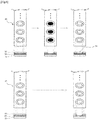
- FIG. 2 illustrates a manufacturing process of a patch manufacturing sheet 30 that is used in a method according to the present disclosure.
- a top view and a cross-sectional view of the patch manufacturing sheet 30 are shown in FIG. 2 .
- a supporting layer 31 is provided as a component of the patch manufacturing sheet 30.
- the supporting layer 31 may be made of a material having superior moisture permeability and stretchability and blocking penetration of drugs and bioactive substances, and a film may be used, wherein the film may be configured with one or more materials selected, for example, among a paper, a non-woven fabric, a woven fabric, a natural or synthetic rubber, polyethylenes terephthalate, polyvinyl chloride, polypropylene, polyurethane, polystyrene, polycarbonate, polyethylenes terephthalate glycol, poly(ethylene-co-vinyl alcohol), polyethylene, polyester, and nylon.
- An adhesive layer 32 is located on an upper surface of the supporting layer 31.
- An adhesive used in the adhesive layer 32 is configured with a pressure sensitive adhesive component that is pharmaceutically usable, and a hydrophilic or organic solvent material and the like may be used.
- an adhesive polymer material an acrylate based resin including an acrylate polymer, a vinyl acetate-acrylate copolymer and the like, a copolymer resin including a polyisobutylene, polystyrene, or polybutadiene copolymer, a rosin based resin, a polyterpene resin, a petroleum based resin, a terpene phenol resin, a silicon polymer, and a natural or synthetic rubber, or a mixture thereof may be used.
- a single adhesive polymer material or two or more mixed adhesive polymer material may be used.
- a peeling film 33 is formed on an upper surface of the adhesive layer 32. As shown in FIG. 2 , if the peeling film 33 is attached to the adhesive layer 32 while a cutting plane line of an approximate double oval shape (not limited to this shape) is formed at the peeling film 33, a portion thereof at which the cutting plane line is formed to be separable from another portion of the peeling film 33, for example, a central small oval portion of the double oval may be easily separated.
- the removing of the central oval portion of the peeling film 33 using the pre-formed cutting plane line thereof is a second procedure, and this second procedure corresponds to a second diagram from a left side of FIG. 2 .
- this second procedure corresponds to a second diagram from a left side of FIG. 2 .
- a bottom layer 34 is covered on the exposed adhesive layer 32.
- the term of the bottom layer 34 is used as a meaning of a bottom at which a microstructure is formed.
- the bottom layer 34 is come into contact with an adhesive of the adhesive layer 32 to maintain a firm coupled state.
- the bottom layer 34 may be any film having a hydrophilic surface so as to allow a microstructure to be formed thereon.
- the bottom layer 34 may be any film having a constant and uniform thickness and a hydrophilic group on a surface thereof. More preferably, the bottom layer 34 may be a hydrophilic polymer film having stretchability of a proper level so as to be tightly attached to a curved portion.
- the bottom layer 34 may be manufactured in advance in a separate process from a microstructure forming process to be attached to the patch manufacturing sheet 30, without being manufactured by the applying procedure of a hydrophilic viscous material and the drying procedure in the microstructure forming process as described in the related art.
- the bottom layer 34 may be coupled to each of a plurality of exposed adhesive layers 32 which are formed at the patch manufacturing sheet 30, whereas, in order to reduce a time required for a process and to increase accuracy of a coupling, the bottom layer 32 and the exposed adhesive layer 32 may be coupled to each other with a method shown in FIG. 3 .
- bottom layers 34 are formed on a sheet that is manufactured in a size the same as that of the patch manufacturing sheet 30.
- a shape and a size of each of the bottom layers 34 correspond to those of each of exposed adhesive layers 32, and a position of each of the bottom layers 34 on the sheet corresponds to that of each of the exposed adhesive layers 32.
- each of the bottom layers 34 is coupled to a corresponding one of the exposed adhesive layers 32 and thus such a coupled state is firmly maintained by a coupling force of the adhesive layer 32. Thereafter, when the sheet at which the bottom layers 34 are formed is released from the contact with the patch manufacturing sheet 30, the plurality of bottom layers 34 may be exactly coupled to all the exposed adhesive layers 32 formed at the patch manufacturing sheet 30 at the same time.
- an inverted sheet surface (a surface of the sheet opposite to a surface thereof at which the plurality of bottom layers 34 have been formed) of the sheet is pressurized by means of a pressurizing device so that a contact state between the bottom layer 34 and the exposed adhesive layer 32 may be certainly accomplished.
- the pressurizing device may be, for example, a roller type or a flat type.
- a forming of a strong contact state may be secured and also a constant pressure is pressurized to an entire of the bottom layer 34 of which is important to be formed with a uniform thickness so that a function of eliminating a certain amount of non-uniformity, which might exist in a thickness of the bottom layer 34 coupled to the patch manufacturing sheet 30, may be performed before the bottom layer 34 is input to the microstructure manufacturing process.
- the bottom layer 34 may be undergone a quality control (QC) process that inspects whether or not the thickness and the like of the bottom layer 34 are manufactured to satisfy a predetermined criterion. Consequently, it may be possible to previously prevent a defect of the microstructure, which may occur when the thickness of the bottom layer 34 being a basis of the formation of the microstructure does not satisfies the predetermined criterion.
- QC quality control
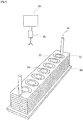
- a plurality of patch manufacturing sheets 30, each of which is formed to be coupled to the bottom layer 34, may be manufactured and then they are provided by one at a time or at the same time to the microstructure forming process. For example, they may be provided to the microstructure forming process under a state as shown in FIG. 4 .
- a hole may be provided at upper and lower parts of the patch manufacturing sheet 30 at which a plurality of patches are formed, and the patch manufacturing sheet 30 may be exactly position-aligned by a bar 41 passing through the hole and may be stacked in plural numbers on a sheet storing substrate 40 to be provided to the microstructure forming process.
- a robot arm including a vacuum suction unit 42 downwardly moves to vacuum suction an upper surface of each of the stored patch manufacturing sheets 30 and then it moves upwardly so that the individual patch manufacturing sheet 30 is guided and upwardly moved along the bars 41 through the holes formed at upper and lower parts of the individual patch manufacturing sheet 30, thereby escaping from the stored state.
- an actuator 43 performing upward, downward, left, and right movements is controlled by a controller, the robot arm may be able to exactly deliver the patch manufacturing sheet 30 to a predetermined substrate position in the microstructure forming process.
- the plurality of patch manufacturing sheets 30 are stacked to be provided to the process as described above, it should be understood that various type process provision methods may be applicable.
- a single patch manufacturing sheet 30 may be provided to the process in a state of being stored on the sheet storing substrate 40.
- FIG. 5 A microstructure forming process on the patch manufacturing sheet 30 according to the present disclosure is shown in FIG. 5 .
- a robot arm approaches and grips the patch manufacturing sheet 30, which is stored on the sheet storing substrate 40 and to which the bottom layer 34 was coupled, using a vacuum suction unit (Operation (a)).
- the robot arm moves to a position at which the microstructure forming process is performing, and downwardly moves to seat the patch manufacturing sheet 30, to which the bottom layer 34 was coupled, on a first process substrate 50 (Operation (b)).
- a forming of a base structure layer is performed.
- the base structure layer is formed by spotting a viscous material on the patch manufacturing sheet 30 to which the bottom layer 34 was coupled.
- a viscous material may be preferable to include a "biocompatible or biodegradable material.”
- biocompatible material means a material having no toxicity to a human body and a chemical inert property.
- biodegradable material means a material that can be decomposed within a human body by body fluid, enzyme, microorganism, or the like.
- the viscous material may be preferable to be dissolved in a proper solvent to appear viscosity.
- viscosity may appear in a state of being melted by heat, but it may appear by dissolving in a solvent.
- the viscous material may include hyaluronic acid or its salt, polyvinylpyrrolidone, polyvinyl alcohol, cellulose polymer, dextran, gelatin, glycerine, polyethylene glycol, polysorbate, propylene glycol, povidone, carbomer, gum ghatti, guar gum, glucomannan, glucosamine, dammar gum, rennet casein, locust bean gum, microfibrillated cellulose, psyllium seed gum, xanthan gum, arabino galactan, arabic gum, alginic acid, gelatin, gellan gum, carrageenan, karaya gum, curdlan, chitosan, chitin, tara gum, tamarind gum, tragacanth gum, furcelleran, pectin, pullulan and the like.
- the viscous material used in the present disclosure may be hydroxypropyl methylcellulose, hydroxyalkyl cellulose, ethyl hydroxyethylcellulose, alkyl cellulose, and carboxymethyl cellulose. Most preferably, the viscous material used in the present disclosure may be carboxymethyl cellulose.
- the solvent for dissolving the viscous material is not specifically limited, and water, absolute or hydrous lower alcohol containing between 1 and 4 carbon atoms, acetone, ethyl acetate, chloroform, 1,3-butylene glycol, hexane, diethyl ether, or butyl acetate may be used as the solvent, and preferably, water or lower alcohol may be used as the solvent, and most preferably, water may be used as the solvent.
- a viscous material forming a base structure layer 35 is spotted at positions spaced apart from each other on the exposed bottom layer 34 at the upper part of the patch manufacturing sheet 30 which is formed by including the bottom layer 34, and then it is coagulated to form the base structure layer 35.
- an air blowing may be performed so as to facilitate a coagulation of the viscous material.
- an arrow represents that the air blowing is performed.
- a diameter of the base structure layer 35 is increased.
- the base structure layer 35 may be formed as high as a desired height by repeating the method for spotting and coagulating the viscous material for forming the base structure layer 35 after the base structure layer 35 has been formed through the coagulation of the viscous material.
- the base structure layer 35 is formed and then the viscous composition is spotted thereon to form a functional material layer 36, whereas in some cases it may be possible to implement an embodiment in which a single functional material layer 36 is formed on the bottom layer 34 without forming two layers of the base structure layer 35 and the functional material layer 36 by repetitively performing the spotting.
- the forming of the base structure layer 35 is omitted and a microneedle is formed with only the functional material layer 36 so that the drug is uniformly distributed to an entire of the microneedle.
- the drug contained in a lower end part of the microneedle may not be totally absorbed into the skin and thus may reside on the bottom layer 34 to reduce a dose amount of a drug so that it may be preferable to form the base structure layer 35 so as to maximize absorbability of a drug.
- the forming of the base structure layer 35 may be omitted so as to simplify the process and increase efficiency.
- the functional material layer 36 is formed with a viscous composition containing a functional material on the base structure layer 35.
- the viscous composition may be made by mixing the viscous material described above with a functional material.
- the viscous composition penetrates into the skin in the case of the microneedle as in the present embodiment, it may be preferable to use a viscous material having superior biocompatible and biodegradable characteristics.
- the functional material includes a material, which penetrates into a skin to act a specific function such as pharmaceutical efficacy, for example, a chemical drug, a protein medicine, a peptide medicine, a nucleic acid molecule for treating a gene, a nanoparticle cosmetic ingredient (for example, a wrinkle-diminishing agent, a skin aging inhibitor, and a skin whitening agent), and the like.
- a material which penetrates into a skin to act a specific function such as pharmaceutical efficacy, for example, a chemical drug, a protein medicine, a peptide medicine, a nucleic acid molecule for treating a gene, a nanoparticle cosmetic ingredient (for example, a wrinkle-diminishing agent, a skin aging inhibitor, and a skin whitening agent), and the like.
- a second process substrate 60 and the patch manufacturing sheet 30 seated thereon are used.
- the bottom layers 34 are formed in advance at the patch manufacturing sheet 30 seated on the second process substrate 60.
- the seating of the patch manufacturing sheet 30 on the second process substrate 60 may be performed by the robot arm as similar to the seating of the patch manufacturing sheet 30 on the first process substrate 50.
- the robot arm may suction and support a single patch manufacturing sheet 30 stored on the sheet storing substrate 40 or a plurality of patch manufacturing sheets 30 which are stacked and stored thereon to seat on a predetermined exact position on the second process substrate 60.
- the second process substrate 60 and the patch manufacturing sheet 30 being seated thereon are inverted to be moved over the first process substrate 50 and the patch manufacturing sheet 30 being seated thereon.
- the second process substrate 60 may include a structure such as a vacuum suction structure and the like.
- a vacuum suction structure In addition to the vacuum suction structure, it should be understood that all structures capable of maintaining the position at which the patch manufacturing sheet 30 has been seated may be included in the scope of the present disclosure.
- the second process substrate 60 is downwardly moved and the patch manufacturing sheet 30 seated thereon comes into contact with the functional material layer 36 spotted on the first process substrate 50. More particularly, the bottom layer 34 of the patch manufacturing sheet 30 seated on the second process substrate 60 comes into contact with the functional material layer 36 on the basis of the base structure layer 35 formed on the bottom layer 34 of the patch manufacturing sheet 30 seated on the first process substrate 50. Meanwhile, in the present disclosure, like the patch manufacturing sheet 30 seated on the first process substrate 50, a spotting of the viscous composition may be performed on the patch manufacturing sheet 30 seated on the second process substrate 60.
- the viscous composition which is spotted on the patch manufacturing sheet 30 provided on the second process substrate 60, comes into contact with the viscous composition, that is, the functional material layer 36, which is spotted on the patch manufacturing sheet 30 provided on the first process substrate 50.
- the second process substrate 60 is relatively moved with respect to the first process substrate 50 (or, the first process substrate 50 is moved with respect to the second process substrate 60), and thus the functional material layer 36 is stretched and is coagulated in the stretched state.
- Conditions of the stretching and the coagulating are described in detail in the description of Korean Patent Application No. 10-2010-0130169 (Title of Invention: Method for Manufacturing a Microstructure) referred to as the related art of the present disclosure, and implementation of the stretching and the coagulating in corresponding Operations of the present disclosure may be performed according to the conditions described in the above-mentioned Korean Patent Application.
- a portion having a minimum diameter of the functional material layer 36 is cut as shown in Operation (i) of FIG. 5 .
- Such a cutting is made by additionally proceeding a relative movement between the first process substrate 50 and the second process substrate 60 under a state in which the functional material layer 36 has been coagulated.
- the portion having the minimum diameter of the functional material layer 36 can be properly cut by an additional stretching in the coagulated state. Consequently, a microneedle structure is formed at both of the patch manufacturing sheet 30 seated on the second process substrate 60 and the patch manufacturing sheet 30 seated on the first process substrate 50.
- the patch manufacturing sheet 30 at which the microstructure (microneedle) was formed may be provided.
- the patch manufacturing sheet 30, at which such a microstructure was formed may be subject to a packaging treatment for protecting the microstructure formed on the sheet, thereby immediately being commercialized.
- the supporting layer 31 which is to form a body of a patch product when being used as the patch product in the future, is formed in plural numbers on the patch manufacturing sheet 30, the patch manufacturing sheet 30 is provided to the microstructure manufacturing process in a state in which the bottom layer 34 is coupled in advance to the supporting layer 31, and the microstructure is formed on the strong basis so that it may hardly damage the bottom layer 34 and the microstructure in the course of being separated from the substrate after the forming process of the microstructure is completed.
- FIG. 6 Another embodiment of FIG. 6 is different from the above described embodiment in terms of an aspect in which a bottom layer 34 is not separately formed.
- a bottom layer 34 is a component serving a function of a bottom at which a microstructure is formed, and it may be any film having a hydrophilic surface so as to allow the microstructure to be formed on the bottom layer 34. Also, such a bottom layer 34 is attached to an adhesive layer 32 which is exposed by removing a central portion of a peeling film 33 along a cutting plane line formed on the peeling film 33 that is a component of a patch manufacturing sheet 30 in the above described embodiment.
- a viscous material configuring the adhesive layer 32 is made of a hydrophilic material that allows the microstructure to be formed thereon instead of not forming the bottom layer 34 separately.
- FIG. 6 By comparing with the embodiment of FIG. 2 , the above described embodiment related to FIG. 2 is shown in an upper portion of FIG. 6 and the present embodiment is shown in a lower portion of FIG. 6 .
- the manufacturing process of the patch manufacturing sheet 30 is configured with the providing of a sheet in a first Operation, the removing of the central portion of the peeling film 33 in a second Operation, and the coupling of the bottom layer 34 in a third Operation, whereas in the embodiment of FIG. 6 , the manufacturing process of the patch manufacturing sheet 30 is configured only with a providing of a sheet in a first Operation, and a removing of a central portion of the peeling film 33 in a second Operation.
- the viscous material configuring the adhesive layer 32 is made of the hydrophilic material that allows the microstructure to be formed thereon, there is an advantage in that the manufacturing process of the patch manufacturing sheet 30 is simplified.
- the hydrophilic material configuring the adhesive layer 32 is an adhesive polymer material having a hydrophilic group.
- the hydrophilic material configuring the adhesive layer 32 which may be usable in the present embodiment, may be a hydrophilic adhesive polymer material which is medically and pharmaceutically usable and has pressure sensitivity.
- a commercially available product containing an acrylate group resin such as an acrylate polymer, a vinyl acetate- acrylate copolymer, and the like may be used.
- the patch manufacturing sheet 30 at which the bottom layer 34 is not separately formed may be implemented in a double layer of the base structure layer 35 and the functional material layer 36, and also it may be implemented to functionally omit the base structure layer 35.
Claims (4)
- Procédé de fabrication d'une microstructure, comprenant les étapes consistant à :fournir une feuille de fabrication de timbres formée dans un état dans lequel une couche inférieure est exposée ;fournir la feuille de fabrication de timbres sur un premier substrat de traitement et un second substrat de traitement ;déposer en gouttes une composition visqueuse au niveau d'une pluralité de positions espacées les unes des autres sur la couche inférieure par rapport à uniquement la feuille de fabrication de timbres fournie sur le premier substrat de traitement, ou au niveau d'une pluralité de positions espacées les unes des autres sur chacune des couches inférieures par rapport à la fois aux feuilles de fabrication de timbres fournies sur le premier substrat de traitement et aux feuilles de fabrication de timbres fournies sur le second substrat de traitement ;mettre en contact la feuille de fabrication de timbres fournie sur le second substrat de traitement avec la composition visqueuse déposée en goutes sur la feuille de fabrication de timbres fournie sur le premier substrat de traitement, ou mettre en contact la composition visqueuse, qui est déposée sur la feuille de fabrication de timbres fournie sur le second substrat de traitement, avec la composition visqueuse déposée en gouttes sur la feuille de fabrication de timbres fournie sur le premier substrat de traitement ;séparer relativement une distance de direction verticale entre le premier substrat de traitement et le second substrat de traitement pour étirer la composition visqueuse et pour coaguler la composition visqueuse étirée ; etdécouper la composition visqueuse coagulée,dans lequel la fourniture de la feuille de fabrication de timbres formée dans un état dans lequel la couche inférieure est exposée inclut les étapes consistant à :fournir la feuille de fabrication de timbres incluant une couche de support, une couche adhésive et un film pelable ;retirer une partie du film pelable de la feuille de fabrication de timbres pour exposer la couche adhésive ; etfixer la couche inférieure à la couche adhésive exposée, dans lequel la couche inférieure est fabriquée pour correspondre à une taille et à une forme de la couche adhésive exposée.
- Procédé de fabrication selon la revendication 1, dans lequel la fourniture de la feuille de fabrication de timbres sur le premier substrat de traitement et le second substrat de traitement aspire sous vide la feuille de fabrication de timbres, qui est stockée sur un substrat de stockage de feuilles et à laquelle la couche inférieure est fixée, en utilisant un bras de robot pour se déplacer vers le premier substrat de traitement et le second substrat de traitement.
- Procédé de fabrication selon la revendication 2, dans lequel un trou est formé au niveau de la feuille de fabrication de timbres à laquelle la couche inférieure est fixée, la feuille de fabrication de timbres à laquelle la couche inférieure est fixée est passée à travers le trou par une barre, qui est formée verticalement au niveau du substrat de stockage de feuilles, étant ainsi stockée sur le substrat de stockage de feuilles d'une manière empilée, et la barre guide un déplacement vertical de la feuille de fabrication de timbres à laquelle la couche inférieure est fixée tandis que le bras de robot aspire sous vide et déplace verticalement la feuille de fabrication de timbres à laquelle la couche inférieure est fixée.
- Procédé de fabrication d'une microstructure, comprenant les étapes consistant à :fournir une feuille de fabrication de timbres formée dans un état dans lequel un adhésif est exposé ;fournir la feuille de fabrication de timbres sur un premier substrat de traitement et un second substrat de traitementdéposer en gouttes une composition visqueuse au niveau d'une pluralité de positions espacées les unes des autres sur la couche adhésive par rapport à uniquement la feuille de fabrication de timbres fournie sur le premier substrat de traitement, ou dans une pluralité de positions espacées les unes des autres sur chacune des couches adhésives par rapport à la fois à la feuille de fabrication de timbres fournie sur le premier substrat de traitement et à la feuille de fabrication de timbres fournie sur le second substrat de traitement ;mettre en contact la feuille de fabrication de timbres fournie sur le second substrat de traitement avec la composition visqueuse déposée en goutes sur la feuille de fabrication de timbres fournie sur le premier substrat de traitement, ou mettre en contact de la composition visqueuse, qui est déposée en gouttes sur la feuille de fabrication de timbres fournie sur le second substrat de traitement, avec la composition visqueuse déposée en gouttes sur la feuille de fabrication de timbres fournie sur le premier substrat de traitement ;séparer relativement une distance de direction verticale entre le premier substrat de traitement et le second substrat de traitement pour étirer la composition visqueuse et pour coaguler la composition visqueuse étirée ; etdécouper la composition visqueuse coagulée,dans lequel un adhésif configurant la couche adhésive est un matériau hydrophile, etdans lequel la fourniture de la feuille de fabrication de timbres formée dans un état dans lequel la couche inférieure est exposée inclut les étapes consistant à :fournir la feuille de fabrication de timbres incluant une couche de support, la couche adhésive et un film pelable ;retirer une partie du film pelable de la feuille de fabrication de timbres pour exposer la couche adhésive.
Applications Claiming Priority (1)
| Application Number | Priority Date | Filing Date | Title |
|---|---|---|---|
| KR1020150174066A KR101636069B1 (ko) | 2015-12-08 | 2015-12-08 | 마이크로구조체 제조방법 |
Publications (3)
| Publication Number | Publication Date |
|---|---|
| EP3178475A1 EP3178475A1 (fr) | 2017-06-14 |
| EP3178475B1 true EP3178475B1 (fr) | 2020-05-27 |
| EP3178475B8 EP3178475B8 (fr) | 2020-07-15 |
Family
ID=56499590
Family Applications (1)
| Application Number | Title | Priority Date | Filing Date |
|---|---|---|---|
| EP16185914.5A Active EP3178475B8 (fr) | 2015-12-08 | 2016-08-26 | Méthode de fabrication d'une microstructure |
Country Status (6)
| Country | Link |
|---|---|
| US (1) | US10231879B2 (fr) |
| EP (1) | EP3178475B8 (fr) |
| JP (1) | JP6290988B2 (fr) |
| KR (1) | KR101636069B1 (fr) |
| CN (1) | CN106853271B (fr) |
| ES (1) | ES2800507T3 (fr) |
Families Citing this family (6)
| Publication number | Priority date | Publication date | Assignee | Title |
|---|---|---|---|---|
| AU2018222745B2 (en) | 2017-02-17 | 2021-02-18 | Allergan, Inc. | Microneedle array with active ingredient |
| CN109420245A (zh) * | 2017-08-30 | 2019-03-05 | 优微(珠海)生物科技有限公司 | 可溶性微针的制造方法 |
| KR102127123B1 (ko) * | 2018-01-11 | 2020-06-26 | 주식회사 라파스 | 마이크로구조체 제조방법 |
| CN109200488B (zh) * | 2018-10-15 | 2020-07-28 | 赵华 | 个体化脑空间125i粒子植入辅助定位器的制作方法 |
| KR102103194B1 (ko) * | 2019-01-07 | 2020-04-22 | 주식회사 라파스 | 생체 친화성 마이크로구조체를 이용한 마이크로구조체 형상 마스터 몰드의 제조방법 |
| KR20230026018A (ko) | 2021-08-17 | 2023-02-24 | 주식회사 이엠코퍼레이션 | 피부 미용 강화형 마이크로 니들 패치 |
Family Cites Families (18)
| Publication number | Priority date | Publication date | Assignee | Title |
|---|---|---|---|---|
| EP0799029A1 (fr) * | 1994-12-21 | 1997-10-08 | Theratech, Inc. | Systeme de liberation transdermique avec opercule adhesif et rondelle pelable |
| JPH10231023A (ja) * | 1997-02-24 | 1998-09-02 | Matsushita Electric Ind Co Ltd | 基板搬送方法および基板搬送カセット |
| CA2330207C (fr) | 1998-06-10 | 2005-08-30 | Georgia Tech Research Corporation | Dispositifs a microaiguilles et procedes de fabrication et d'utilisation correspondants |
| US6092981A (en) * | 1999-03-11 | 2000-07-25 | Applied Materials, Inc. | Modular substrate cassette |
| JP2005154321A (ja) | 2003-11-25 | 2005-06-16 | Nano Device & System Research Inc | アスコルビン酸投与用マイクロニードル |
| US7588705B2 (en) * | 2004-12-28 | 2009-09-15 | Nabtesco Corporation | Skin needle manufacturing apparatus and skin needle manufacturing method |
| US7955677B2 (en) * | 2005-12-07 | 2011-06-07 | Mylan Technologies, Inc. | Two-sided non-stick release film |
| CN104377151B (zh) * | 2009-09-28 | 2019-01-01 | 株式会社尼康 | 加压装置及控制方法 |
| JP5558772B2 (ja) * | 2009-10-08 | 2014-07-23 | 東レエンジニアリング株式会社 | マイクロニードルシートのスタンパー及びその製造方法とそれを用いたマイクロニードルの製造方法 |
| US8294264B2 (en) * | 2010-03-30 | 2012-10-23 | Taiwan Semiconductor Manufacturing Company, Ltd. | Radiate under-bump metallization structure for semiconductor devices |
| US8545741B2 (en) * | 2010-04-01 | 2013-10-01 | Nurim Wellness Co. Ltd. | Method of manufacturing microstructure |
| KR101254240B1 (ko) * | 2010-12-17 | 2013-04-12 | 주식회사 라파스 | 마이크로구조체 제조방법 |
| KR20100130169A (ko) | 2010-09-27 | 2010-12-10 | 강민수 | 텍스트 콘텐츠에 광고 콘텐츠를 결합하여 광고하는 방법 |
| KR20110116110A (ko) * | 2011-10-07 | 2011-10-25 | 주식회사 누리엠웰니스 | 송풍에 의한 솔리드 마이크로구조체의 제조방법 |
| KR101285085B1 (ko) * | 2012-03-22 | 2013-07-17 | 주식회사 라파스 | 마이크로니들 제조장치 |
| KR101435888B1 (ko) * | 2012-10-23 | 2014-09-01 | 연세대학교 산학협력단 | 히알루론산을 이용한 생분해성 마이크로니들 제조방법 |
| MY175783A (en) * | 2013-03-26 | 2020-07-08 | Mitsui Chemicals Tohcello Inc | Production method for laminate film, laminate film, and production method for semiconductor device employing same |
| CN105556654B (zh) * | 2013-09-26 | 2019-07-26 | 应用材料公司 | 用于传送基板的气动终端受动器装置、基板传送系统与方法 |
-
2015
- 2015-12-08 KR KR1020150174066A patent/KR101636069B1/ko active IP Right Grant
-
2016
- 2016-07-22 JP JP2016144857A patent/JP6290988B2/ja active Active
- 2016-08-12 CN CN201610663744.0A patent/CN106853271B/zh active Active
- 2016-08-26 ES ES16185914T patent/ES2800507T3/es active Active
- 2016-08-26 US US15/248,339 patent/US10231879B2/en active Active
- 2016-08-26 EP EP16185914.5A patent/EP3178475B8/fr active Active
Non-Patent Citations (1)
| Title |
|---|
| None * |
Also Published As
| Publication number | Publication date |
|---|---|
| ES2800507T3 (es) | 2020-12-30 |
| US20170156935A1 (en) | 2017-06-08 |
| JP6290988B2 (ja) | 2018-03-07 |
| US10231879B2 (en) | 2019-03-19 |
| CN106853271B (zh) | 2020-01-14 |
| EP3178475B8 (fr) | 2020-07-15 |
| CN106853271A (zh) | 2017-06-16 |
| KR101636069B1 (ko) | 2016-07-11 |
| JP2017104490A (ja) | 2017-06-15 |
| EP3178475A1 (fr) | 2017-06-14 |
Similar Documents
| Publication | Publication Date | Title |
|---|---|---|
| EP3178475B1 (fr) | Méthode de fabrication d'une microstructure | |
| US20240066277A1 (en) | Methods for manufacturing microprojection arrays | |
| KR101747099B1 (ko) | 생체적합성 고분자를 이용한 마이크로니들의 제조방법 | |
| EP2934660B1 (fr) | Micro-réseau pour la distribution d'un agent thérapeutique et son procédé de fabrication | |
| JP2020203127A (ja) | 治療剤の送達のためのマイクロアレイ、使用方法および製造方法 | |
| JP2016512754A5 (fr) | ||
| JP2016511014A5 (fr) | ||
| KR20170132087A (ko) | 사마귀 치료를 위한 블레오마이신을 함유하는 마이크로니들 패치 및 이의 제작방법 | |
| KR20170067637A (ko) | 마이크로구조체 제조방법 | |
| KR102127123B1 (ko) | 마이크로구조체 제조방법 |
Legal Events
| Date | Code | Title | Description |
|---|---|---|---|
| PUAI | Public reference made under article 153(3) epc to a published international application that has entered the european phase |
Free format text: ORIGINAL CODE: 0009012 |
|
| STAA | Information on the status of an ep patent application or granted ep patent |
Free format text: STATUS: REQUEST FOR EXAMINATION WAS MADE |
|
| 17P | Request for examination filed |
Effective date: 20160826 |
|
| AK | Designated contracting states |
Kind code of ref document: A1 Designated state(s): AL AT BE BG CH CY CZ DE DK EE ES FI FR GB GR HR HU IE IS IT LI LT LU LV MC MK MT NL NO PL PT RO RS SE SI SK SM TR |
|
| AX | Request for extension of the european patent |
Extension state: BA ME |
|
| STAA | Information on the status of an ep patent application or granted ep patent |
Free format text: STATUS: EXAMINATION IS IN PROGRESS |
|
| 17Q | First examination report despatched |
Effective date: 20180823 |
|
| GRAP | Despatch of communication of intention to grant a patent |
Free format text: ORIGINAL CODE: EPIDOSNIGR1 |
|
| STAA | Information on the status of an ep patent application or granted ep patent |
Free format text: STATUS: GRANT OF PATENT IS INTENDED |
|
| INTG | Intention to grant announced |
Effective date: 20200312 |
|
| GRAS | Grant fee paid |
Free format text: ORIGINAL CODE: EPIDOSNIGR3 |
|
| GRAA | (expected) grant |
Free format text: ORIGINAL CODE: 0009210 |
|
| STAA | Information on the status of an ep patent application or granted ep patent |
Free format text: STATUS: THE PATENT HAS BEEN GRANTED |
|
| RAP1 | Party data changed (applicant data changed or rights of an application transferred) |
Owner name: RAPHAS CO., LTD. |
|
| AK | Designated contracting states |
Kind code of ref document: B1 Designated state(s): AL AT BE BG CH CY CZ DE DK EE ES FI FR GB GR HR HU IE IS IT LI LT LU LV MC MK MT NL NO PL PT RO RS SE SI SK SM TR |
|
| REG | Reference to a national code |
Ref country code: GB Ref legal event code: FG4D |
|
| REG | Reference to a national code |
Ref country code: CH Ref legal event code: EP |
|
| RAP2 | Party data changed (patent owner data changed or rights of a patent transferred) |
Owner name: RAPHAS CO., LTD. |
|
| REG | Reference to a national code |
Ref country code: AT Ref legal event code: REF Ref document number: 1273812 Country of ref document: AT Kind code of ref document: T Effective date: 20200615 |
|
| REG | Reference to a national code |
Ref country code: DE Ref legal event code: R096 Ref document number: 602016036938 Country of ref document: DE |
|
| REG | Reference to a national code |
Ref country code: CH Ref legal event code: PK Free format text: BERICHTIGUNG B8 |
|
| REG | Reference to a national code |
Ref country code: LT Ref legal event code: MG4D |
|
| PG25 | Lapsed in a contracting state [announced via postgrant information from national office to epo] |
Ref country code: FI Free format text: LAPSE BECAUSE OF FAILURE TO SUBMIT A TRANSLATION OF THE DESCRIPTION OR TO PAY THE FEE WITHIN THE PRESCRIBED TIME-LIMIT Effective date: 20200527 Ref country code: NO Free format text: LAPSE BECAUSE OF FAILURE TO SUBMIT A TRANSLATION OF THE DESCRIPTION OR TO PAY THE FEE WITHIN THE PRESCRIBED TIME-LIMIT Effective date: 20200827 Ref country code: PT Free format text: LAPSE BECAUSE OF FAILURE TO SUBMIT A TRANSLATION OF THE DESCRIPTION OR TO PAY THE FEE WITHIN THE PRESCRIBED TIME-LIMIT Effective date: 20200928 Ref country code: GR Free format text: LAPSE BECAUSE OF FAILURE TO SUBMIT A TRANSLATION OF THE DESCRIPTION OR TO PAY THE FEE WITHIN THE PRESCRIBED TIME-LIMIT Effective date: 20200828 Ref country code: LT Free format text: LAPSE BECAUSE OF FAILURE TO SUBMIT A TRANSLATION OF THE DESCRIPTION OR TO PAY THE FEE WITHIN THE PRESCRIBED TIME-LIMIT Effective date: 20200527 Ref country code: IS Free format text: LAPSE BECAUSE OF FAILURE TO SUBMIT A TRANSLATION OF THE DESCRIPTION OR TO PAY THE FEE WITHIN THE PRESCRIBED TIME-LIMIT Effective date: 20200927 Ref country code: SE Free format text: LAPSE BECAUSE OF FAILURE TO SUBMIT A TRANSLATION OF THE DESCRIPTION OR TO PAY THE FEE WITHIN THE PRESCRIBED TIME-LIMIT Effective date: 20200527 |
|
| REG | Reference to a national code |
Ref country code: NL Ref legal event code: MP Effective date: 20200527 |
|
| PG25 | Lapsed in a contracting state [announced via postgrant information from national office to epo] |
Ref country code: HR Free format text: LAPSE BECAUSE OF FAILURE TO SUBMIT A TRANSLATION OF THE DESCRIPTION OR TO PAY THE FEE WITHIN THE PRESCRIBED TIME-LIMIT Effective date: 20200527 Ref country code: RS Free format text: LAPSE BECAUSE OF FAILURE TO SUBMIT A TRANSLATION OF THE DESCRIPTION OR TO PAY THE FEE WITHIN THE PRESCRIBED TIME-LIMIT Effective date: 20200527 Ref country code: LV Free format text: LAPSE BECAUSE OF FAILURE TO SUBMIT A TRANSLATION OF THE DESCRIPTION OR TO PAY THE FEE WITHIN THE PRESCRIBED TIME-LIMIT Effective date: 20200527 Ref country code: BG Free format text: LAPSE BECAUSE OF FAILURE TO SUBMIT A TRANSLATION OF THE DESCRIPTION OR TO PAY THE FEE WITHIN THE PRESCRIBED TIME-LIMIT Effective date: 20200827 |
|
| REG | Reference to a national code |
Ref country code: AT Ref legal event code: MK05 Ref document number: 1273812 Country of ref document: AT Kind code of ref document: T Effective date: 20200527 |
|
| PG25 | Lapsed in a contracting state [announced via postgrant information from national office to epo] |
Ref country code: AL Free format text: LAPSE BECAUSE OF FAILURE TO SUBMIT A TRANSLATION OF THE DESCRIPTION OR TO PAY THE FEE WITHIN THE PRESCRIBED TIME-LIMIT Effective date: 20200527 Ref country code: NL Free format text: LAPSE BECAUSE OF FAILURE TO SUBMIT A TRANSLATION OF THE DESCRIPTION OR TO PAY THE FEE WITHIN THE PRESCRIBED TIME-LIMIT Effective date: 20200527 |
|
| PG25 | Lapsed in a contracting state [announced via postgrant information from national office to epo] |
Ref country code: AT Free format text: LAPSE BECAUSE OF FAILURE TO SUBMIT A TRANSLATION OF THE DESCRIPTION OR TO PAY THE FEE WITHIN THE PRESCRIBED TIME-LIMIT Effective date: 20200527 Ref country code: CZ Free format text: LAPSE BECAUSE OF FAILURE TO SUBMIT A TRANSLATION OF THE DESCRIPTION OR TO PAY THE FEE WITHIN THE PRESCRIBED TIME-LIMIT Effective date: 20200527 Ref country code: RO Free format text: LAPSE BECAUSE OF FAILURE TO SUBMIT A TRANSLATION OF THE DESCRIPTION OR TO PAY THE FEE WITHIN THE PRESCRIBED TIME-LIMIT Effective date: 20200527 Ref country code: SM Free format text: LAPSE BECAUSE OF FAILURE TO SUBMIT A TRANSLATION OF THE DESCRIPTION OR TO PAY THE FEE WITHIN THE PRESCRIBED TIME-LIMIT Effective date: 20200527 Ref country code: EE Free format text: LAPSE BECAUSE OF FAILURE TO SUBMIT A TRANSLATION OF THE DESCRIPTION OR TO PAY THE FEE WITHIN THE PRESCRIBED TIME-LIMIT Effective date: 20200527 Ref country code: DK Free format text: LAPSE BECAUSE OF FAILURE TO SUBMIT A TRANSLATION OF THE DESCRIPTION OR TO PAY THE FEE WITHIN THE PRESCRIBED TIME-LIMIT Effective date: 20200527 |
|
| PG25 | Lapsed in a contracting state [announced via postgrant information from national office to epo] |
Ref country code: SK Free format text: LAPSE BECAUSE OF FAILURE TO SUBMIT A TRANSLATION OF THE DESCRIPTION OR TO PAY THE FEE WITHIN THE PRESCRIBED TIME-LIMIT Effective date: 20200527 Ref country code: PL Free format text: LAPSE BECAUSE OF FAILURE TO SUBMIT A TRANSLATION OF THE DESCRIPTION OR TO PAY THE FEE WITHIN THE PRESCRIBED TIME-LIMIT Effective date: 20200527 |
|
| REG | Reference to a national code |
Ref country code: DE Ref legal event code: R097 Ref document number: 602016036938 Country of ref document: DE |
|
| PG25 | Lapsed in a contracting state [announced via postgrant information from national office to epo] |
Ref country code: MC Free format text: LAPSE BECAUSE OF FAILURE TO SUBMIT A TRANSLATION OF THE DESCRIPTION OR TO PAY THE FEE WITHIN THE PRESCRIBED TIME-LIMIT Effective date: 20200527 |
|
| REG | Reference to a national code |
Ref country code: CH Ref legal event code: PL |
|
| PLBE | No opposition filed within time limit |
Free format text: ORIGINAL CODE: 0009261 |
|
| STAA | Information on the status of an ep patent application or granted ep patent |
Free format text: STATUS: NO OPPOSITION FILED WITHIN TIME LIMIT |
|
| PG25 | Lapsed in a contracting state [announced via postgrant information from national office to epo] |
Ref country code: LI Free format text: LAPSE BECAUSE OF NON-PAYMENT OF DUE FEES Effective date: 20200831 Ref country code: LU Free format text: LAPSE BECAUSE OF NON-PAYMENT OF DUE FEES Effective date: 20200826 Ref country code: CH Free format text: LAPSE BECAUSE OF NON-PAYMENT OF DUE FEES Effective date: 20200831 |
|
| 26N | No opposition filed |
Effective date: 20210302 |
|
| REG | Reference to a national code |
Ref country code: BE Ref legal event code: MM Effective date: 20200831 |
|
| PG25 | Lapsed in a contracting state [announced via postgrant information from national office to epo] |
Ref country code: SI Free format text: LAPSE BECAUSE OF FAILURE TO SUBMIT A TRANSLATION OF THE DESCRIPTION OR TO PAY THE FEE WITHIN THE PRESCRIBED TIME-LIMIT Effective date: 20200527 |
|
| PG25 | Lapsed in a contracting state [announced via postgrant information from national office to epo] |
Ref country code: BE Free format text: LAPSE BECAUSE OF NON-PAYMENT OF DUE FEES Effective date: 20200831 Ref country code: IE Free format text: LAPSE BECAUSE OF NON-PAYMENT OF DUE FEES Effective date: 20200826 |
|
| PG25 | Lapsed in a contracting state [announced via postgrant information from national office to epo] |
Ref country code: TR Free format text: LAPSE BECAUSE OF FAILURE TO SUBMIT A TRANSLATION OF THE DESCRIPTION OR TO PAY THE FEE WITHIN THE PRESCRIBED TIME-LIMIT Effective date: 20200527 Ref country code: MT Free format text: LAPSE BECAUSE OF FAILURE TO SUBMIT A TRANSLATION OF THE DESCRIPTION OR TO PAY THE FEE WITHIN THE PRESCRIBED TIME-LIMIT Effective date: 20200527 Ref country code: CY Free format text: LAPSE BECAUSE OF FAILURE TO SUBMIT A TRANSLATION OF THE DESCRIPTION OR TO PAY THE FEE WITHIN THE PRESCRIBED TIME-LIMIT Effective date: 20200527 |
|
| PG25 | Lapsed in a contracting state [announced via postgrant information from national office to epo] |
Ref country code: MK Free format text: LAPSE BECAUSE OF FAILURE TO SUBMIT A TRANSLATION OF THE DESCRIPTION OR TO PAY THE FEE WITHIN THE PRESCRIBED TIME-LIMIT Effective date: 20200527 |
|
| PGFP | Annual fee paid to national office [announced via postgrant information from national office to epo] |
Ref country code: IT Payment date: 20230713 Year of fee payment: 8 Ref country code: GB Payment date: 20230829 Year of fee payment: 8 Ref country code: ES Payment date: 20230908 Year of fee payment: 8 |
|
| PGFP | Annual fee paid to national office [announced via postgrant information from national office to epo] |
Ref country code: FR Payment date: 20230717 Year of fee payment: 8 Ref country code: DE Payment date: 20230809 Year of fee payment: 8 |