EP3178360B1 - Procede de liaison interposee d'une plaque de support et d'une paroi d'un sac d'aspirateur et sac d'aspirateur - Google Patents
Procede de liaison interposee d'une plaque de support et d'une paroi d'un sac d'aspirateur et sac d'aspirateur Download PDFInfo
- Publication number
- EP3178360B1 EP3178360B1 EP15199696.4A EP15199696A EP3178360B1 EP 3178360 B1 EP3178360 B1 EP 3178360B1 EP 15199696 A EP15199696 A EP 15199696A EP 3178360 B1 EP3178360 B1 EP 3178360B1
- Authority
- EP
- European Patent Office
- Prior art keywords
- wall
- vacuum cleaner
- retaining plate
- filter bag
- cleaner filter
- Prior art date
- Legal status (The legal status is an assumption and is not a legal conclusion. Google has not performed a legal analysis and makes no representation as to the accuracy of the status listed.)
- Active
Links
- 238000000034 method Methods 0.000 title claims description 44
- 239000000463 material Substances 0.000 claims description 197
- 239000004753 textile Substances 0.000 claims description 137
- 239000012815 thermoplastic material Substances 0.000 claims description 66
- 238000003466 welding Methods 0.000 claims description 32
- 229920002725 thermoplastic elastomer Polymers 0.000 claims description 25
- 229920001169 thermoplastic Polymers 0.000 claims description 18
- 239000004416 thermosoftening plastic Substances 0.000 claims description 16
- -1 polyethylene Polymers 0.000 claims description 15
- 239000004743 Polypropylene Substances 0.000 claims description 14
- 239000004745 nonwoven fabric Substances 0.000 claims description 13
- 239000000853 adhesive Substances 0.000 claims description 10
- 230000001070 adhesive effect Effects 0.000 claims description 10
- 238000004519 manufacturing process Methods 0.000 claims description 10
- 238000007789 sealing Methods 0.000 claims description 10
- 239000004698 Polyethylene Substances 0.000 claims description 6
- 229920000728 polyester Polymers 0.000 claims description 6
- 229920000573 polyethylene Polymers 0.000 claims description 6
- 229920000098 polyolefin Polymers 0.000 claims description 6
- 229920001155 polypropylene Polymers 0.000 claims description 6
- 238000002604 ultrasonography Methods 0.000 claims description 6
- 239000004744 fabric Substances 0.000 claims description 4
- 239000000203 mixture Substances 0.000 claims description 4
- 239000004696 Poly ether ether ketone Substances 0.000 claims description 2
- 239000004952 Polyamide Substances 0.000 claims description 2
- 239000004721 Polyphenylene oxide Substances 0.000 claims description 2
- 239000004734 Polyphenylene sulfide Substances 0.000 claims description 2
- 239000004793 Polystyrene Substances 0.000 claims description 2
- 239000007788 liquid Substances 0.000 claims description 2
- 229920002647 polyamide Polymers 0.000 claims description 2
- 229920002480 polybenzimidazole Polymers 0.000 claims description 2
- 229920006393 polyether sulfone Polymers 0.000 claims description 2
- 229920002530 polyetherether ketone Polymers 0.000 claims description 2
- 229920001601 polyetherimide Polymers 0.000 claims description 2
- 229920000193 polymethacrylate Polymers 0.000 claims description 2
- 229920006380 polyphenylene oxide Polymers 0.000 claims description 2
- 229920000069 polyphenylene sulfide Polymers 0.000 claims description 2
- 229920002223 polystyrene Polymers 0.000 claims description 2
- 239000004810 polytetrafluoroethylene Substances 0.000 claims description 2
- 229920001343 polytetrafluoroethylene Polymers 0.000 claims description 2
- 238000002844 melting Methods 0.000 description 23
- 230000008018 melting Effects 0.000 description 23
- 239000000155 melt Substances 0.000 description 22
- 239000010410 layer Substances 0.000 description 18
- 239000011888 foil Substances 0.000 description 9
- 238000004026 adhesive bonding Methods 0.000 description 8
- 239000002131 composite material Substances 0.000 description 4
- 238000009736 wetting Methods 0.000 description 4
- 239000000835 fiber Substances 0.000 description 3
- 238000007639 printing Methods 0.000 description 3
- 238000007650 screen-printing Methods 0.000 description 3
- 238000005520 cutting process Methods 0.000 description 2
- 239000000428 dust Substances 0.000 description 2
- 229920001971 elastomer Polymers 0.000 description 2
- 238000001746 injection moulding Methods 0.000 description 2
- 230000007246 mechanism Effects 0.000 description 2
- 239000004033 plastic Substances 0.000 description 2
- 229920003023 plastic Polymers 0.000 description 2
- 238000004080 punching Methods 0.000 description 2
- 230000002787 reinforcement Effects 0.000 description 2
- 239000005060 rubber Substances 0.000 description 2
- 230000015572 biosynthetic process Effects 0.000 description 1
- 230000001419 dependent effect Effects 0.000 description 1
- 238000011161 development Methods 0.000 description 1
- 230000018109 developmental process Effects 0.000 description 1
- 238000009826 distribution Methods 0.000 description 1
- 230000000694 effects Effects 0.000 description 1
- 239000012065 filter cake Substances 0.000 description 1
- 239000012943 hotmelt Substances 0.000 description 1
- 238000002347 injection Methods 0.000 description 1
- 239000007924 injection Substances 0.000 description 1
- 238000000465 moulding Methods 0.000 description 1
- 239000002356 single layer Substances 0.000 description 1
- 239000002759 woven fabric Substances 0.000 description 1
Images


Classifications
-
- A—HUMAN NECESSITIES
- A47—FURNITURE; DOMESTIC ARTICLES OR APPLIANCES; COFFEE MILLS; SPICE MILLS; SUCTION CLEANERS IN GENERAL
- A47L—DOMESTIC WASHING OR CLEANING; SUCTION CLEANERS IN GENERAL
- A47L9/00—Details or accessories of suction cleaners, e.g. mechanical means for controlling the suction or for effecting pulsating action; Storing devices specially adapted to suction cleaners or parts thereof; Carrying-vehicles specially adapted for suction cleaners
- A47L9/10—Filters; Dust separators; Dust removal; Automatic exchange of filters
- A47L9/14—Bags or the like; Rigid filtering receptacles; Attachment of, or closures for, bags or receptacles
- A47L9/1427—Means for mounting or attaching bags or filtering receptacles in suction cleaners; Adapters
- A47L9/1436—Connecting plates, e.g. collars, end closures
Definitions
- the present invention relates to a method for producing an improved material bond between a holding plate and the wall of a vacuum cleaner filter bag.
- the holding plate is not applied directly to the wall of the vacuum cleaner filter bag, but instead a textile material is arranged between the holding plate and the wall.
- the bond between the holding plate and the wall of the vacuum cleaner filter bag is achieved via the textile material.
- a film made of a thermoplastic material is arranged between the wall of the vacuum cleaner filter bag and the holding plate in some areas between the holding plate and the wall of the vacuum cleaner filter bag.
- the connection between the holding plate and the wall of the vacuum cleaner filter bag is achieved via the foil.
- the holding plate is connected directly to the wall of the vacuum cleaner filter bag.
- the wall is in the form of a film, at least in the area in which the holding plate is applied formed from special thermoplastic materials-
- the present invention also relates to vacuum cleaner filter bags in which the holding plate is integrally connected to the wall of the vacuum cleaner filter bag according to the above principles.
- a vacuum cleaner bag holding plate to the non-woven fabric of a filter bag is done by gluing using a thermally activated adhesive (e.g. hotmelt) or by ultrasonic welding. Because of the short welding time and the high strength and process reliability of the welded joint, this is the preferred choice.
- a thermally activated adhesive e.g. hotmelt
- Direction indicators on the holding plate and structuring on the sonotrode or on the anvil further increase the performance of ultrasonic welding.
- the DE 20 2008 002 010 U1 describes a filter bag for a vacuum cleaner, the filter bag having a dust collection bag which is connected to a holding plate which has a passage opening for a vacuum cleaner nozzle, which is provided with a seal made of a polymeric material.
- the dust collection bag is glued and/or welded directly to the seal.
- the DE 20 2008 004 025 U1 describes a filter, in particular a vacuum cleaner bag, with a filter material on which an inflow opening is provided, in which a sealing device for producing a seal with a socket is provided, which is arranged adjacent to a holding plate.
- the sealing device has at least one elastic rubber layer with an opening through another more rigid Materialla ge is reinforced with an opening aligned with the opening of the rubber layer.
- a vacuum cleaner filter bag a filter bag material that has an inner layer of fleece material at least in the area of the inlet opening, and a holding plate arranged on the outside of the filter bag in the area of the inlet opening, which can be attached to a holding device of a vacuum cleaner for holding the vacuum cleaner filter bag and on which a closure device for closing the inlet opening is provided, wherein the fleece material has a surface in the region of the inlet opening, which is provided in such a way that the formation of a filter cake on this surface is avoided.
- the object of the present invention to specify reliable methods for connecting a holding plate to the wall of a vacuum cleaner filter bag, with which the aforementioned disadvantages can be avoided.
- the bond between the retaining plate and the wall of the filter bag should be easy to implement, the bond produced should withstand high tensile loads, and the results obtained should also be reproducible.
- the invention thus relates to a method for the integral connection of a holding plate to the wall of a vacuum cleaner filter bag.
- the wall of the vacuum cleaner filter bag has a location provided for attaching the retaining plate. Depending on the configuration of the vacuum cleaner filter bag to be produced later from the wall of the vacuum cleaner filter bag, this location can be located at different points.
- a material, non-positive or positive connection of the wall of the vacuum cleaner filter bag is produced with at least one, in particular exactly one layer of a textile material, and the Holding plate is pressed against the textile material side of the wall of the vacuum cleaner filter bag at the place of attachment. A material connection is then produced between the wall of the vacuum cleaner filter bag, the textile material and the retaining plate.
- At least one layer of a textile material for example a A single layer of a textile material is applied to the wall of the vacuum cleaner filter bag at the attachment point of the holding plate and is connected there at least in certain areas to the wall of the vacuum cleaner filter bag.
- the place of attachment is understood to mean the area of the wall of the vacuum cleaner filter bag on which the holding plate is later arranged, i.e. the area of the wall which is defined by the outline of the holding plate in projection onto the wall.
- the application of the textile material can only take place in areas of the attachment location, so that only part of the surface on which the holding plate is later arranged is provided with a textile material.
- This embodiment is particularly useful if it is only sufficient as a punctiform or regional reinforcement of the bond between the holding plate and the wall of the vacuum cleaner filter bag.
- One or more strips of textile material can also be sufficient for reinforcement.
- the area of the composite e.g. the weld, which is subject to the greatest stress, can be reinforced.
- the area of the textile material prefferably be larger than the area of the attachment location, so that after the holding plate has been connected to the wall, textile material protrudes below the holding plate.
- the at least regional connection of the textile material to the wall can be done, for example, by spot welding, spot gluing, but also by mechanical permanent or temporary fixations, such as clamp connections, etc.
- the retaining plate is pressed onto the textile material in such a way that at least part of the surface of the retaining plate comes to rest on the textile material. It is also possible that the entire area of the holding plate is adapted to the textile material, in the event that the area of the Textile material is correspondingly large, ie at least as large as the base of the retaining plate.
- a cohesive bond is produced between the wall of the vacuum cleaner filter bag and the retaining plate through the textile material.
- This can be done, for example, by welding, in particular ultrasonic welding, or by gluing.
- an adhesive is already applied to the textile material, the holding plate or the textile material and the holding plate before the holding plate is pressed onto the textile material.
- a second variant of the first aspect of the invention provides that at least in some areas of the holding plate, a material, non-positive or positive connection of the holding plate with at least one, in particular exactly one layer of a textile material is produced, and the holding plate with the the side provided with the textile material is pressed against the wall of the vacuum cleaner filter bag at the place of attachment.
- a cohesive bond is then produced between the wall and the textile material in the manner described above.
- the textile material is fixed at least in certain areas to the retaining plate, the retaining plate is then pressed together with the textile material that is fixed at least in certain areas to the place of attachment on the wall of the vacuum cleaner filter bag and connected to it through the textile material.
- the textile material can, for example, only be attached in areas of the holding plate, for example in such a way that the textile material does not fill the entire surface of the holding plate, or that an edge of the holding plate is surmounted by the textile material, but not the entire surface of the holding plate later attached to the wall is covered by the textile material. It is also possible for the textile material to cover the entire surface of the holding plate, also in such a way that the textile material protrudes beyond the edge of the holding plate.
- a passage opening can be made in the textile material before or after application to the holding plate - in the event that it is arranged on the holding plate in such a way that the entry opening is partially or completely covered .
- the passage opening can also be introduced after the connection between the holding plate and the wall of the vacuum cleaner filter bag has been produced.
- connection of the textile material to the retaining plate can be carried out analogously to the explanations for connecting the textile material to the wall according to the first variant, i.e. also, for example, by spot welding, spot adhesion, but also via mechanical permanent or temporary fixations, such as clamp connections, etc.
- the textile material can, for example, already be introduced into the injection mold and thus be connected to the holding plate directly during the injection molding process.
- connection of the holding plate provided with the textile material is otherwise identical to the first variant, i. H. here, too, a corresponding gluing or welding of the retaining plate to the wall can be carried out via the textile material.
- a third variant of the first aspect of the method according to the invention it is provided that at least one, in particular exactly one layer of a textile material is introduced between the wall of the vacuum cleaner filter bag and the holding plate, at least in some areas in the area of the attachment location of the holding plate, the holding plate together with the textile material on Place of attachment is pressed against the wall of the vacuum cleaner filter bag.
- the textile material is introduced without prior fixation between the wall and the holding plate, for example inserted at the intended location; there is only a single binding process in which the holding plate is connected through the textile material to the wall of the vacuum cleaner filter bag.
- the textile material can only be applied in areas of the attachment location in accordance with the above statements, so that only part of the surface on which the holding plate is later arranged is provided with a textile material. It is also possible to equip the entire area that defines the attachment point of the retaining plate with a textile material. It is also possible to select the area of the textile material to be larger than the area of the attachment location, so that after the holding plate has been connected to the wall, textile material protrudes below the holding plate.
- the wall of the vacuum cleaner filter bag comprises or consists of or is formed from a thermoplastic material at least in the region of the attachment location of the retaining plate.
- thermoplastic materials that come into question for the wall of the vacuum cleaner filter bag are polyolefins, in particular polyethylene, polypropylene or polystyrene, polyester, in particular PET, PBT, PC or PLA, thermoplastic elastomers, in particular TPE-O, TPE-V, TPE- U, TPE-E, TPE-S or TPE-A, poly(meth)acrylates, polyamides, polybenzimidazoles, polyethersulfones, polyetheretherketones, polyetherimides, polyphenylene oxides, polyphenylene sulfides and polytetrafluoroethylene and mixtures, blends or combinations thereof.
- the wall of the vacuum cleaner filter bag can be formed, for example, as a film or as a non-woven material, at least in the area where the holding plate is attached.
- the textile material comprises or consists of or is formed from thermoplastic fibers and/or thermoplastic filaments.
- thermoplastic fibers or filaments of the textile material can be formed from the same or different materials that were previously mentioned for the wall of the vacuum cleaner filter bag.
- At least the support side of the holding plate comprises a thermoplastic material at least in regions or consists or is formed entirely of a thermoplastic material or the entire holding plate consists or is formed of a thermoplastic material.
- thermoplastic materials mentioned above for the wall of the vacuum cleaner filter bag are also particularly suitable for the purposes of the retaining plate.
- the materials of the holding plate can represent the same or different materials that are used for the wall of the vacuum cleaner filter bag or the textile material.
- thermoplastic materials of the textile material thus melt sooner, i.e. at lower temperatures, than the thermoplastic materials of the wall and/or the holding plate and/or have a lower viscosity at the same temperature. Due to the better melting and/or the low viscosity of the melt of these materials, improved wetting of the wall and the holding plate is effected, especially in the case of a welded joint, so that a significant improvement in the bond between the holding plate and the wall of the vacuum cleaner filter bag can be observed.
- thermoplastic material for the wall of the vacuum cleaner filter bag is polyolefins, in particular polypropylene or polyethylene, polyester or - in the event that the wall is designed as a film laminate at least at the place of attachment - thermoplastic polymers, in particular TPE or TPU as the layer of this laminate facing the holding plate to call.
- polyolefins such as polypropylene or polyethylene or polyester, in particular PET, are used as materials for the holding plate.
- the materials that are particularly suitable for the textile material are preferably thermoplastic elastomers such as TPE or TPU.
- the textile material it is also possible for the textile material to be formed from the same thermoplastics as the retaining plate or the wall; in this case, however, it is preferred, as described above, if the thermoplastic material has a lower melting point. If, for example, both the wall, the holding plate and the textile material are made of PP, it is advantageous to use a type of PP for the textile material that has a lower melting point and/or a higher MFI than the PP Grades used for retaining plate and wall.
- the textile material is selected from the group consisting of non-woven fabrics, nets, woven fabrics, knitted fabrics, scrims, crocheted fabrics, braids, stitch-knitted fabrics and felts and combinations thereof.
- Nonwovens and nets (nettings) are particularly preferred here, spunbonded nonwovens and carded nonwovens being particularly preferred among the nonwovens.
- the textile material is flat and in particular has a basis weight of 5 to 200 g/m 2 , preferably 10 to 100 g/m 2 , particularly preferably 15 to 50 g/m 2 .
- the advantages of the present invention come into play in particular when the wall of the vacuum cleaner filter bag, at least in the area in which the holding plate is to be fixed, as a film made of a thermoplastic material, a film laminate, in which at least the side on which the holding plate is applied is made of a thermoplastic material, or is formed of a non-woven fabric made of a thermoplastic material.
- the smooth surface of the foil makes it difficult to securely weld a retaining plate to the foil. It is assumed that, particularly during the welding process, the film or film laminate cannot be completely wetted. Surprisingly, the wetting of the film or film laminate in particular can be improved if a textile material is arranged between the holding plate and the film or film laminate. It is particularly preferred here if the textile material itself consists of a thermoplastic material, in particular of a thermoplastic elastomer, and also melts, for example, during the welding process. In this way, significantly better wetting of the film can be achieved, so that the resulting maximum tensile force, which can act on the retaining plate before the retaining plate is partially or completely torn off, can be significantly improved.
- an inlet opening contained in the holding plate, into which a vacuum cleaner socket can be inserted, for example, is arranged flush with the bag inlet opening and the passage opening.
- the geometric shape of the textile material can depend on the weld seam geometry to be achieved.
- the weld seam is typically round and has a width of a few mm to cm. It is therefore sufficient to position a corresponding ring made of textile material between the film and the holding plate and to connect it to the film and the holding plate in one step using the known ultrasonic welding process.
- the textile material can, for. B. be formed as a strip of material that can be wider than the desired weld to facilitate positioning.
- the diameter of the bag inlet opening of the wall of the vacuum cleaner filter bag and/or the passage opening of the textile material can be dimensioned smaller or the same size as the inlet opening of the holding plate.
- This embodiment provides that either the bag inlet opening of the wall of the vacuum cleaner filter bag, or the through-opening of the textile material, or the bag inlet opening of the wall of the vacuum cleaner filter bag and the through-opening of the textile material are dimensioned smaller in diameter than the inlet opening of the holding plate.
- This resulting overhang in the direction of the recess (filling hole) forms a seal that can be used to seal the nozzle of the vacuum cleaner to be inserted through the inlet opening of the holding plate into the interior of the resulting vacuum cleaner filter bag.
- a good sealing effect can be observed in particular with a smaller dimensioning of the passage opening of the textile material (and possibly also the bag inlet opening of the wall of the vacuum cleaner filter bag).
- the textile material can additionally be connected, for example welded, to the wall of the vacuum cleaner filter bag in the region of this overhang. However, it is also possible to leave the textile material unconnected to the wall of the vacuum cleaner filter bag in this area.
- At least one flat sealing element which is preferably made of TPE or TPU, is introduced at the attachment point of the holding plate on the inside of the wall of the vacuum cleaner filter bag, between the wall of the vacuum cleaner filter bag and the textile material and/or between the textile material and the holding plate is formed and has a through-opening which is arranged flush with the through-opening of the holding plate, but has a smaller diameter than the diameter of the through-opening of the holding plate.
- the contact side of the holding plate is structured at least in regions and/or has direction indicators for ultrasound.
- a directional indicator can be formed, for example, as a raised groove on the attachment side of the retaining plate.
- the wall of the vacuum cleaner filter bag is designed as a film or film laminate at least in the area where the holding plate is attached, the film or film laminate is structured at least at the attachment point, in particular high-low structured, such as knurled.
- the film used can also be a laminate of two different thermoplastics.
- the layer of the laminate that can be activated more easily by ultrasound points towards the holding plate. If this layer is a TPE, for example, and the holding plate with the in the EP2311358 A1 equipped with the TPE welding aid described above, a particularly good connection is achieved. In this case, too, the additional introduction of a textile material is advantageous.
- a further particularly preferred embodiment provides that on the wall, at least in the attachment location of the retaining plate, on the wall and/or on the side of the textile material facing the wall and/or on the side of the textile material facing the retaining plate, a thermoplastic elastomer, such as in particular TPE-O, TPE-V, TPE-U, TPE-E, TPE-S or TPE-A is applied, for example via a printing process, in particular by means of functional screen printing.
- the thermoplastic elastomer can be applied to the respective surface in the form of nubs or concentric circles, for example.
- the present invention relates to a further method for cohesively connecting a holding plate to the wall of a vacuum cleaner filter bag at an attachment location provided for this purpose.
- no textile material is used between the retaining plate and the wall to reinforce the composite, but rather a film made of a thermoplastic material, which is only used in one area of the attachment site.
- the second aspect of the method according to the invention is also designed in three variants.
- a material, non-positive or form-fitting connection is made in certain areas in the area of the mounting location of the holding plate Bonding of the wall of the vacuum cleaner filter bag with at least one, in particular precisely one layer of film made of a thermoplastic material, the retaining plate pressed against the side of the wall of the vacuum cleaner filter bag provided with the film at the place of attachment and then a bonded bond between the wall of the vacuum cleaner filter bag and the film and the holding plate made.
- a material, non-positive or positive connection of the holding plate with at least one, in particular exactly one layer of a film made of a thermoplastic material is produced in certain areas on the holding plate, at least in areas, and the holding plate with the side provided with the film on Place of attachment pressed against the wall of the vacuum cleaner filter bag and then a cohesive bond between the wall of the vacuum cleaner filter bag, the film and the retaining plate is produced.
- At least one layer, in particular exactly one layer, of a film made of a thermoplastic material is inserted between the wall of the vacuum cleaner filter bag and the retaining plate in the region of the attachment point of the retaining plate, the retaining plate together with the film is pressed against the wall of the vacuum cleaner filter bag at the attachment point and then a material connection between the wall of the vacuum cleaner filter bag, the foil and the retaining plate is produced.
- the film is preferably formed from a thermoplastic material which has a melting temperature which is lower than or equal to, preferably lower, particularly preferably at least 10 °C lower, in particular at least 20 °C lower than the melting temperature of the thermoplastic material of the wall of the Vacuum cleaner filter bag and/or as the melting temperature of the thermoplastic material of the holding plate (5), the melting temperature being determined in each case according to ISO 11357, and/or having a melt flow index (melt flow rate (MFR)) which is greater than or equal to, preferably greater than is particularly preferably greater by a factor of 10 to 20 than the melt flow index of the thermoplastic material of the wall (1) of the vacuum cleaner filter bag and/or than the melt flow index of the thermoplastic material of the holding plate (5), the melt flow index being determined in each case according to ISO 1133 a rated load of 2.16 kg and a temperature of 230 °C.
- MFR melt flow rate
- the materials that can be used in particular for the film correspond to the materials that were mentioned as preferred materials for the textile materials mentioned above.
- the film that is introduced between the holding plate and the wall is preferably designed as a strip of material.
- the film is not arranged in the area of the inlet opening of the holding plate or the bag inlet opening of the wall of the vacuum cleaner filter bag, but more preferably in the edge area of the mounting location of the holding plate.
- the area in which the film is arranged makes up preferably 5 to 70%, more preferably 10 to 50%, particularly preferably 15 to 25% of the area of the attachment site of the holding plate.
- the film placed between the wall and the retaining plate can be continuous or slotted and/or perforated.
- thermoplastic elastomer such as in particular TPE-O, TPE-V, TPE-U, TPE-E, TPE-S or TPE-A is applied, for example via a printing process, in particular by means of functional screen printing.
- the thermoplastic elastomer can be applied to the respective surface in the form of nubs or concentric circles, for example.
- this second aspect of the invention is identical to the first aspect.
- connection options with which the film can be connected to the wall or the retaining plate at least in some areas correspond to those that have already been discussed in the first aspect of the present invention.
- spot or full-area welding or gluing come into question here.
- the final production of the bond between the wall, film and retaining plate also takes place analogously to the production of the bond between the wall, textile material and retaining plate according to the first aspect of the invention.
- a third aspect of the present invention relates to a further method for cohesively connecting a holding plate to the wall of a vacuum cleaner filter bag at an attachment location provided for this purpose.
- no additional material is introduced between the wall and the retaining plate.
- the holding plate is connected directly to the wall of the vacuum cleaner filter bag.
- thermoplastic materials of the film or the side of the film facing the retaining plate thus melt more readily, ie at lower temperatures, than the thermoplastic materials of the retaining plate and/or have a lower viscosity at the same temperature. Due to the better melting and/or the low viscosity of the melt of these materials, improved wetting of the wall—in this case the film—and the holding plate is effected, particularly in the case of a welded joint, so that a more significant Improvement of the bond between the retaining plate and the wall of the vacuum cleaner filter bag can be observed.
- thermoplastic material for the film of the wall of the vacuum cleaner filter bag is polyolefins, in particular polypropylene or polyethylene, polyester or - in the event that the wall is designed as a film laminate at least at the point of attachment - thermoplastic polymers, in particular TPE or TPU as the layer facing the holding plate of this laminate.
- polyolefins such as polypropylene or polyethylene or polyester, in particular PET, are used as materials for the holding plate.
- thermoplastic elastomers such as TPE or TPU.
- the film or the film laminate it is also possible for the film or the film laminate to be formed from the same thermoplastic as the retaining plate or the wall. In this case, however, it is preferred, as described above, if the thermoplastic material has a lower melting point. If, for example, both the retaining plate and the film or the film laminate are made of PP, it is advantageous to use a PP type for the film or the film laminate that has a lower melting point and/or a higher MFI. like the PP grades used for the backing plate and wall.
- thermoplastic elastomer such as in particular TPE-O, TPE-V, TPE-U, TPE-E, TPE -S or TPE-A is applied, for example via a printing process, in particular by means of functional screen printing.
- the thermoplastic elastomer can be applied to the respective surface in the form of nubs or concentric circles, for example.
- the holding plate can also have a closure flap that protrudes through the bag inlet opening into the interior of the vacuum cleaner filter bag and by means of which the bag inlet opening can be closed from the inside.
- This flap can, for example, have a spring, by means of which the bag inlet opening can be self-sealed with the flap.
- the present invention relates to a vacuum cleaner filter bag, comprising a wall with an attachment point for a retaining plate, and a retaining plate which is materially connected to the wall at the attachment point and which is connected to the wall at least in regions via at least one, in particular precisely one layer of textile material.
- the wall of the vacuum cleaner filter bag is made of a film made of a thermoplastic material, a film laminate, in which at least the side to which the holding plate is attached is made of a thermoplastic material, or of a nonwoven fabric made of a thermoplastic material is formed.
- the wall of the vacuum cleaner filter bag has a bag inlet opening in the area of the attachment location
- the textile material has a through-opening
- the retaining plate has an inlet opening, with the bag inlet opening, through-opening and inlet opening being aligned one above the other, in particular that the bag inlet opening and/or the through-opening in the Diameter are smaller or the same size as the input opening.
- At least one flat sealing element preferably made of TPE, is placed at the attachment point of the retaining plate on the inside of the wall of the vacuum cleaner filter bag, between the wall of the vacuum cleaner filter bag and the textile material and/or between the textile material and the retaining plate or TPU and which has a through-opening which is arranged flush with the through-opening of the holding plate, but has a smaller diameter than the diameter of the through-opening of the holding plate.
- the invention also relates to a vacuum cleaner filter bag, comprising a wall with an attachment point for a retaining plate, and a retaining plate which is materially connected to the wall at the attachment point and which is connected to the wall in some areas via at least one, in particular exactly one layer of a film made of a thermoplastic material .
- the vacuum cleaner filter bag according to this variant is essentially identical to the previously mentioned embodiment, apart from the fact that the holding plate is connected to the wall of the filter bag via a film that is only provided in certain areas at the attachment location.
- the preferred passage opening is made in the film.
- the vacuum cleaner filter bags according to all embodiments can be made from the walls described at the outset and produced according to the invention be made up using production methods known from the prior art, for example as a flat bag or as a block-bottom bag.
- figure 1 shows a first method according to the invention for producing a wall according to the invention, having an inlet opening, for a vacuum cleaner filter bag.
- a wall 1 of a vacuum cleaner filter bag is provided.
- the wall can be a nonwoven material or a film, for example.
- laminates made of nonwovens or foils are conceivable. These materials can, for example, be provided from rolls and unwound endlessly.
- Figure 1a (as well as in all the following figures), only a small section of the material of the wall 1 of the vacuum cleaner filter bag is shown.
- Figure 1b shows the state after a textile material 2 has been applied to one side of the wall 1 of the vacuum cleaner filter bag by means of four separate individual welding points 3. The remaining surface of the textile material 2 is loose and not connected to the wall of the filter bag.
- the textile material 2 can also be bonded to the wall 1 of the vacuum cleaner filter bag at certain points. It is also possible to connect the textile material 2 to the wall 1 of the vacuum cleaner filter bag over the entire surface, for example by welding or gluing.
- Figure 1d shows the state after a holding plate 5 with an associated inlet opening 6 has been applied in alignment to the common opening (4, 4') of the composite of wall 1 of the filter material and textile material 2. It can be seen that the passage opening 6 of the holding plate 5 has a larger diameter than the common opening (4, 4') of the wall of the filter bag and the textile material. This overhang, which is visible inside the inlet opening of the holding plate, acts as a seal for a vacuum cleaner socket to be inserted through the inlet opening 6 of the holding plate 5 .
- the joint bond between the holding plate 5 and the wall 1 of the vacuum cleaner filter bag via the textile material 2 is achieved, for example, by an ultrasonic welding process in which ultrasound is introduced into the holding plate by means of a sonotrode and anvil.
- the weld seam can, for example, be annular around the inlet opening 6 of the holding plate 5, but it is also possible to weld the holding plate 5 only at certain points via the textile material 2 to the wall 1 of the vacuum cleaner filter bag. It is also possible to weld the holding plate 5 to the wall 1 of the vacuum cleaner filter bag over the entire surface via the textile material 2 .
- Both the wall 1, the textile material 2 and the retaining plate 5 are formed from thermoplastic materials in this example.
- figure 2 shows a further embodiment for the production of a vacuum cleaner filter bag according to the invention.
- the textile material is smaller in size.
- the textile material is only fixed to the wall 1 of the vacuum cleaner filter bag at two points 3 (for example by welding or gluing).
- the holding plate 5 When the holding plate 5 is superimposed, with the inlet opening of the holding plate 6 also being brought into alignment with the bag inlet opening 4 , the holding plate 5 thus only rests on the textile material 2 in certain areas.
- the textile material 2 With the wall 1 of the vacuum cleaner filter bag (for example via a welding process), only the area in which the textile material 2 is present is particularly reinforced. This is sufficient, for example, if there is a known tensile load on the vacuum cleaner filter bag.
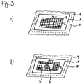
- figure 3 shows a further embodiment of a method according to the invention for producing a vacuum cleaner filter bag according to the invention.
- Figure 3a is identical to Figure 1a ) or.
- Figure 2a the material of the wall of the vacuum cleaner filter bag is designed as a non-woven fabric.
- a recess A is made in the wall 1 of the vacuum cleaner filter bag. This can be done, for example, by punching out or cutting out.
- thermoplastic film F covering the recess A is now fixed to the wall 1 of the vacuum cleaner filter bag, for example by welding or gluing, on the rear side of the wall 1 of the vacuum cleaner filter bag shown in perspective.
- a textile material 2 is fixed to the film F, for example by means of four spot welds 3 .
- the mounting plate 5 with the inlet opening 6 After the mounting plate 5 with the inlet opening 6 has been applied, the mounting plate is fixed by the textile material 2 to the film F, which forms the wall 1 of the vacuum cleaner filter bag in this area.
Landscapes
- Engineering & Computer Science (AREA)
- Mechanical Engineering (AREA)
- Filters For Electric Vacuum Cleaners (AREA)
- Filtering Materials (AREA)
- Adhesives Or Adhesive Processes (AREA)
Claims (18)
- Procédé pour relier par liaison de matière une plaque de retenue (5) à la paroi (1) d'un sac filtrant d'aspirateur à un emplacement de fixation prévu à cet effet, dans lequela) au moins par endroits, dans la zone de l'emplacement de fixation de la plaque de retenue (5), un assemblage (3) par liaison de matière, adhérence ou complémentarité de forme de la paroi (1) du sac filtrant d'aspirateur avec au moins une et en particulier exactement une couche d'un matériau textile (2) est réalisé, la plaque de retenue (5) est pressée contre le côté pourvu du matériau textile (2) de la paroi du sac filtrant d'aspirateur à l'emplacement de fixation, oub) au moins par endroits, sur la plaque de retenue (5), un assemblage par liaison de matière, adhérence ou complémentarité de forme de la plaque de retenue (5) avec au moins une et en particulier exactement une couche d'un matériau textile (2) est réalisé, et la plaque de retenue (5) est pressée avec le côté pourvu du matériau textile (2) contre la paroi (1) du sac filtrant d'aspirateur à l'emplacement de fixation, ouc) au moins une et en particulier exactement une couche d'un matériau textile (2) est introduite entre la paroi (1) du sac filtrant d'aspirateur et la plaque de retenue (5) au moins par endroits dans la zone de l'emplacement de fixation de la plaque de retenue (5), la plaque de retenue (5) est pressée avec le matériau textile (2) contre la paroi (1) du sac filtrant d'aspirateur à l'emplacement de fixation,puis un assemblage par liaison de matière est réalisé entre la paroi (1) du sac filtrant d'aspirateur, le matériau textile (2) et la plaque de retenue (5).
- Procédé selon la revendication 1, caractérisé en ce quela paroi (1) du sac filtrant d'aspirateur comprend ou est constituée ou formée d'un matériau thermoplastique au moins dans la zone de l'emplacement de fixation de la plaque de retenue (5),le matériau textile (2) comprend ou est constitué ou formé de fibres thermoplastiques et/ou de filaments thermoplastiques, et/ouau moins la face de support de la plaque de retenue (5) comprend ou est entièrement constituée ou formée au moins par endroits d'un matériau thermoplastique ou l'ensemble de la plaque de retenue (5) est constitué ou formé d'un matériau thermoplastique.
- Procédé selon l'une des deux revendications précédentes, caractérisé en ce que le matériau thermoplastique de la paroi (1) du sac filtrant d'aspirateur, le matériau à partir duquel les fibres thermoplastiques et/ou les filaments thermoplastiques du matériau textile (2) sont formés et/ou le matériau thermoplastique de la plaque de retenue (5) sont choisis chacun indépendamment les uns des autres dans le groupe constitué par les polyoléfines, en particulier le polyéthylène, le polypropylène ou le polystyrène, les poly(méth)acrylates, les polyamides, les polyesters, en particulier le PET, le PBT, le PC ou le PLA, les élastomères thermoplastiques (TPE), en particulier les TPE-O, TPE-V, TPE-U, TPE-E, TPE-S ou TPE-A, les polybenzimidazoles, les polyéthersulfones, les polyétheréthercétones, les polyétherimides, les oxydes de polyphénylène, les sulfures de polyphénylène et le polytétrafluoroéthylène, ainsi que des mélanges ou combinaisons de ceux-ci.
- Procédé selon l'une des revendications précédentes, caractérisé en ce que le matériau textile (2) est choisi dans le groupe constitué par les non-tissés, les filets, les tissus tissés, les tissus maillés, les nappes, les tricots, les tresses, les tissus obtenus par couture-tricotage et les feutres, ainsi que des combinaisons de ceux-ci.
- Procédé selon la revendication précédente, caractérisé en ce que le non-tissé est choisi dans le groupe constitué par les non-tissés filés et les non-tissés cardés.
- Procédé selon l'une des revendications précédentes, caractérisé en ce que le matériau textile (2) est plat et présente en particulier un grammage de 5 à 200 g/m2, de préférence de 10 à 100 g/m2, plus préférablement de 15 à 50 g/m2.
- Procédé selon l'une des revendications précédentes, caractérisé en ce que la paroi (1) du sac filtrant d'aspirateur est formée, au moins à l'emplacement de fixation de la plaque de retenue (5), d'une feuille (F) en matériau thermoplastique, d'un stratifié de feuilles dans lequel au moins le côté sur lequel la plaque de retenue (5) est appliquée est constitué d'un matériau thermoplastique, ou d'un non-tissé constitué d'un matériau thermoplastique.
- Procédé selon l'une des revendications précédentes, caractérisé en ce quea) la liaison au moins par endroits de la paroi (1) du sac filtrant d'aspirateur au matériau textile (2) par liaison de matière, adhérence ou complémentarité de forme,b) la liaison au moins par endroits de la plaque de retenue (5) au matériau textile (2) par liaison de matière, adhérence ou complémentarité de forme, et/ouc) la réalisation finale de l'assemblage par liaison de matière entre la paroi (1) du sac filtrant d'aspirateur, le matériau textile (2) et la plaque de retenue (5)s'effectue au moyen d'une opération de soudage, en particulier d'une opération de soudage par ultrasons ou d'une opération de collage, en particulier au moyen d'une colle liquide, d'une colle à deux composants ou d'une colle pouvant être liquéfiée thermiquement.
- Procédé selon l'une des revendications précédentes, caractérisé en ce que
la paroi (1) du sac filtrant d'aspirateur présente dans la zone de l'emplacement de fixation une ouverture d'entrée de sac (4), le matériau textile (2) une ouverture de passage (4) et la plaque de retenue (5) une ouverture d'entrée (6), dans lequel l'ouverture d'entrée de sac (4), l'ouverture de passage (4) et l'ouverture d'entrée (6) sont amenées à coïncider les unes avec les autres, ou une ouverture d'entrée de sac (4) est pratiquée dans la paroi (1) du sac filtrant d'aspirateur dans la zone de l'emplacement de fixation et/ou une ouverture de passage (4) est pratiquée dans le matériau textile (2), et l'ouverture d'entrée de sac (4), l'ouverture de passage (4) et l'ouverture d'entrée (6) de la plaque de retenue (5) sont amenées à coïncider les unes avec les autres. - Procédé selon la revendication précédente, caractérisé en ce que le diamètre de l'ouverture d'entrée de sac (4) et/ou de l'ouverture de passage (4) est inférieur ou égal au diamètre de l'ouverture d'entrée (6).
- Procédé selon l'une des revendications précédentes, caractérisé en ce qu'à l'emplacement de fixation de la plaque de retenue (5), au moins un élément d'étanchéité plat est disposé sur la face intérieure de la paroi (1) du sac filtrant d'aspirateur, entre la paroi (1) du sac filtrant d'aspirateur et le matériau textile (2) et/ou entre le matériau textile (2) et la plaque de retenue (5), lequel élément d'étanchéité est de préférence constitué de TPE ou de TPU et présente une ouverture de passage qui coïncide avec l'ouverture de passage de la plaque de retenue (5) mais présente un diamètre inférieur au diamètre de l'ouverture de passage de la plaque de retenue (5).
- Procédé selon l'une des revendications précédentes, caractérisé en ce que
la face de support de la plaque de retenue (5) est structurée au moins par endroits et/ou présente des capteurs de direction pour ultrasons, et/ou, dans le cas où la paroi (1) du sac filtrant d'aspirateur est réalisée sous la forme d'une feuille (F) ou d'un stratifié de feuilles au moins dans la zone de l'emplacement de fixation de la plaque de retenue (5), la feuille (F) ou le stratifié de feuilles est structuré(e) au moins à l'emplacement de fixation, en particulier structuré(e) en profondeur, par exemple moleté(e). - Procédé pour relier par liaison de matière une plaque de retenue (5) à la paroi (1) d'un sac filtrant d'aspirateur à un emplacement de fixation prévu à cet effet, dans lequela) au moins par endroits, dans la zone de l'emplacement de fixation de la plaque de retenue (5), un assemblage (3) par liaison de matière, adhérence ou complémentarité de forme de la paroi (1) du sac filtrant d'aspirateur avec au moins une et en particulier exactement une couche d'une feuille (F) en matériau thermoplastique est réalisé, la plaque de retenue (5) est pressée contre le côté pourvu de la feuille de la paroi du sac filtrant d'aspirateur à l'emplacement de fixation, oub) au moins par endroits, sur la plaque de retenue (5), un assemblage par liaison de matière, adhérence ou complémentarité de forme de la plaque de retenue (5) avec au moins une et en particulier exactement une couche d'une feuille (F) en matériau thermoplastique est réalisé, et la plaque de retenue (5) est pressée avec le côté pourvu de la feuille (F) contre la paroi (1) du sac filtrant d'aspirateur à l'emplacement de fixation, ouc) au moins une et en particulier exactement une couche d'une feuille (F) en matériau thermoplastique est introduite entre la paroi (1) du sac filtrant d'aspirateur et la plaque de retenue (5) par endroits dans la zone de l'emplacement de fixation de la plaque de retenue (5), la plaque de retenue (5) est pressée avec la feuille contre la paroi (1) du sac filtrant d'aspirateur à l'emplacement de fixation,puis un assemblage par liaison de matière est réalisé entre la paroi (1) du sac filtrant d'aspirateur, la feuille (F) et la plaque de retenue (5).
- Sac filtrant d'aspirateur, comprenant une paroi (1) avec un emplacement de fixation pour une plaque de retenue (5), ainsi qu'une plaque de retenue (5) reliée à la paroi (1) par liaison de matière à l'emplacement de fixation, laquelle plaque de retenue est reliée à la paroi (1) au moins par endroits par une couche d'un matériau textile (2).
- Sac filtrant d'aspirateur selon la revendication précédente, caractérisé en ce que la paroi (1) du sac filtrant d'aspirateur est formée, au moins à l'emplacement de fixation de la plaque de retenue (5), d'une feuille (F) en matériau thermoplastique, d'un stratifié de feuilles dans lequel au moins le côté sur lequel la plaque de retenue (5) est appliquée est constitué d'un matériau thermoplastique ou d'un non-tissé constitué d'un matériau thermoplastique.
- Sac filtrant d'aspirateur selon l'une des deux revendications précédentes, caractérisé en ce que la paroi (1) du sac filtrant d'aspirateur présente dans la zone de l'emplacement de fixation une ouverture d'entrée de sac (4), le matériau textile une ouverture de passage (4') et la plaque de retenue (5) une ouverture d'entrée (6), dans lequel l'ouverture d'entrée de sac (4), l'ouverture de passage (4') et l'ouverture d'entrée (6) sont amenées à coïncider les unes avec les autres, en particulier en ce que le diamètre de l'ouverture d'entrée de sac (4) et/ou de l'ouverture de passage (4') est inférieur ou égal au diamètre de l'ouverture d'entrée (6).
- Sac filtrant d'aspirateur selon l'une des revendications 14 à 16, caractérisé en ce qu'à l'emplacement de fixation de la plaque de retenue (5), au moins un élément d'étanchéité plat est disposé sur la face intérieure de la paroi (1) du sac filtrant d'aspirateur, entre la paroi (1) du sac filtrant d'aspirateur et le matériau textile (2) et/ou entre le matériau textile (2) et la plaque de retenue (5), lequel élément d'étanchéité est de préférence constitué de TPE ou de TPU et présente une ouverture de passage qui coïncide avec l'ouverture de passage (6) de la plaque de retenue (5) mais présente un diamètre inférieur au diamètre de l'ouverture de passage (6) de la plaque de retenue (5).
- Sac filtrant d'aspirateur, comprenant une paroi (1) avec un emplacement de fixation pour une plaque de retenue (5), ainsi qu'une plaque de retenue (5) reliée à la paroi (1) par liaison de matière à l'emplacement de fixation, laquelle plaque de retenue est reliée à la paroi (1) par endroits par une couche d'une feuille (F) en matériau thermoplastique.
Priority Applications (10)
| Application Number | Priority Date | Filing Date | Title |
|---|---|---|---|
| ES15199696T ES2916748T3 (es) | 2015-12-12 | 2015-12-12 | Procedimiento para producir una unión por material entre una placa de retención y la pared de una bolsa de filtro de aspiradora, así como bolsa de filtro de aspiradora |
| EP15199696.4A EP3178360B1 (fr) | 2015-12-12 | 2015-12-12 | Procede de liaison interposee d'une plaque de support et d'une paroi d'un sac d'aspirateur et sac d'aspirateur |
| CN201680081239.3A CN108697286B (zh) | 2015-12-12 | 2016-12-12 | 用于将吸尘器过滤袋的保持板与壁部材料接合地连接的方法以及吸尘器过滤袋 |
| US16/060,746 US10925450B2 (en) | 2015-12-12 | 2016-12-12 | Method for integral connection of a retaining plate to the wall of a vacuum cleaner filter bag and also vacuum cleaner filter bag |
| ES16809066T ES2972226T3 (es) | 2015-12-12 | 2016-12-12 | Procedimiento para conectar por unión de materiales una placa de sujeción a la pared de una bolsa de filtro de aspiradora y bolsa de filtro de aspiradora |
| PL16809066.0T PL3386363T3 (pl) | 2015-12-12 | 2016-12-12 | Sposób łączenia połączeniem spajanym płytki mocującej ze ścianką worka filtracyjnego i worek filtracyjny do odkurzacza |
| DK16809066.0T DK3386363T3 (da) | 2015-12-12 | 2016-12-12 | Fremgangsmåde til at forbinde en holdeplade materialesluttende til væggen af en støvsugerfilterpose samt støvsugerfilterpose |
| AU2016366505A AU2016366505B2 (en) | 2015-12-12 | 2016-12-12 | Method for integrally connecting a retaining plate to the wall of a vacuum-cleaner filter bag, and vacuum-cleaner filter bag |
| PCT/EP2016/080568 WO2017098035A1 (fr) | 2015-12-12 | 2016-12-12 | Procédé pour effectuer une liaison de matière entre une plaque de retenue et la paroi d'un sac filtrant d'aspirateur et sac filtrant d'aspirateur |
| EP16809066.0A EP3386363B1 (fr) | 2015-12-12 | 2016-12-12 | Procede de liaison interposee d'une plaque de support et d'une paroi d'un sac d'aspirateur et sac d'aspirateur |
Applications Claiming Priority (1)
| Application Number | Priority Date | Filing Date | Title |
|---|---|---|---|
| EP15199696.4A EP3178360B1 (fr) | 2015-12-12 | 2015-12-12 | Procede de liaison interposee d'une plaque de support et d'une paroi d'un sac d'aspirateur et sac d'aspirateur |
Publications (2)
| Publication Number | Publication Date |
|---|---|
| EP3178360A1 EP3178360A1 (fr) | 2017-06-14 |
| EP3178360B1 true EP3178360B1 (fr) | 2022-03-16 |
Family
ID=55027273
Family Applications (2)
| Application Number | Title | Priority Date | Filing Date |
|---|---|---|---|
| EP15199696.4A Active EP3178360B1 (fr) | 2015-12-12 | 2015-12-12 | Procede de liaison interposee d'une plaque de support et d'une paroi d'un sac d'aspirateur et sac d'aspirateur |
| EP16809066.0A Active EP3386363B1 (fr) | 2015-12-12 | 2016-12-12 | Procede de liaison interposee d'une plaque de support et d'une paroi d'un sac d'aspirateur et sac d'aspirateur |
Family Applications After (1)
| Application Number | Title | Priority Date | Filing Date |
|---|---|---|---|
| EP16809066.0A Active EP3386363B1 (fr) | 2015-12-12 | 2016-12-12 | Procede de liaison interposee d'une plaque de support et d'une paroi d'un sac d'aspirateur et sac d'aspirateur |
Country Status (8)
| Country | Link |
|---|---|
| US (1) | US10925450B2 (fr) |
| EP (2) | EP3178360B1 (fr) |
| CN (1) | CN108697286B (fr) |
| AU (1) | AU2016366505B2 (fr) |
| DK (1) | DK3386363T3 (fr) |
| ES (2) | ES2916748T3 (fr) |
| PL (1) | PL3386363T3 (fr) |
| WO (1) | WO2017098035A1 (fr) |
Families Citing this family (7)
| Publication number | Priority date | Publication date | Assignee | Title |
|---|---|---|---|---|
| RU2694075C1 (ru) * | 2016-05-09 | 2019-07-09 | Актиеболагет Электролюкс | Пылесборник для пылесоса |
| ES2876182T3 (es) | 2018-02-23 | 2021-11-12 | Eurofilters Holding Nv | Placa de sujeción con elemento de junta |
| DE202018102370U1 (de) | 2018-04-27 | 2018-05-04 | Eurofilters Holding N.V. | Staubsaugerfilterbeutel mit Folie im Bereich der Halteplatte |
| EP3560402B1 (fr) * | 2018-04-27 | 2022-12-07 | Eurofilters Holding N.V. | Élément filtrant d'aspirateur sous pourvu de feuille dans la zone de la plaque de retenue |
| PL3669734T3 (pl) * | 2018-12-17 | 2021-07-05 | Eurofilters Holding N.V. | Worek filtracyjny do odkurzacza mający spoinę zgrzewaną o ulepszonej wytrzymałości |
| EP3821777A1 (fr) * | 2019-11-12 | 2021-05-19 | Eurofilters Holding N.V. | Sac filtrant d'aspirateur pour un aspirateur à main |
| EP3821776A1 (fr) * | 2019-11-12 | 2021-05-19 | Eurofilters Holding N.V. | Sac filtrant d'aspirateur pour un aspirateur à main |
Family Cites Families (13)
| Publication number | Priority date | Publication date | Assignee | Title |
|---|---|---|---|---|
| US20010047721A1 (en) * | 2000-05-03 | 2001-12-06 | Scanlon John J. | Vacuum collection bag and method of operation |
| DE20101471U1 (de) * | 2001-01-27 | 2001-04-19 | Wolf GmbH, 32602 Vlotho | Filtervorrichtung für einen Staubsauger |
| DE102005059214B4 (de) * | 2005-12-12 | 2007-10-25 | Eurofilters N.V. | Filterbeutel für einen Staubsauger |
| DE202005021619U1 (de) * | 2005-12-15 | 2008-12-24 | Eurofilters N.V. | Filterbeutel |
| DE102006023707B3 (de) * | 2006-05-19 | 2008-01-03 | Eurofilters N.V. | Staubfilterbeutel |
| DE102006029059A1 (de) * | 2006-06-24 | 2007-12-27 | Branofilter Gmbh | Filtereinrichtung für Staubsauger und Verfahren zur Herstellung der Filtereinrichtung |
| ATE431095T1 (de) * | 2007-08-17 | 2009-05-15 | Eurofilters Holding Nv | Staubsaugerfilterbeutel |
| DE202008002010U1 (de) * | 2008-02-13 | 2008-06-26 | Aichner Filter Gmbh | Filterbeutel für einen Staubsauger |
| ES2440722T3 (es) * | 2008-03-07 | 2014-01-30 | Eurofilters Holding N.V. | Bolsa de filtro de aspiradora |
| DE202008004025U1 (de) * | 2008-03-20 | 2009-08-06 | Wolf Pvg Gmbh & Co. Kg | Filter |
| EP2263508B1 (fr) * | 2009-06-19 | 2015-08-05 | Eurofilters N.V. | Sac plat pour aspirateur avec au moins deux diffuseurs |
| ES2560672T3 (es) | 2009-10-19 | 2016-02-22 | Eurofilters Holding N.V. | Placa de sujeción para una bolsa filtrante de aspiradora |
| ES2534100T3 (es) * | 2011-12-22 | 2015-04-17 | Eurofilters N.V. | Placa de sujeción |
-
2015
- 2015-12-12 EP EP15199696.4A patent/EP3178360B1/fr active Active
- 2015-12-12 ES ES15199696T patent/ES2916748T3/es active Active
-
2016
- 2016-12-12 PL PL16809066.0T patent/PL3386363T3/pl unknown
- 2016-12-12 AU AU2016366505A patent/AU2016366505B2/en active Active
- 2016-12-12 CN CN201680081239.3A patent/CN108697286B/zh active Active
- 2016-12-12 ES ES16809066T patent/ES2972226T3/es active Active
- 2016-12-12 EP EP16809066.0A patent/EP3386363B1/fr active Active
- 2016-12-12 WO PCT/EP2016/080568 patent/WO2017098035A1/fr active Application Filing
- 2016-12-12 US US16/060,746 patent/US10925450B2/en active Active
- 2016-12-12 DK DK16809066.0T patent/DK3386363T3/da active
Also Published As
| Publication number | Publication date |
|---|---|
| US10925450B2 (en) | 2021-02-23 |
| AU2016366505B2 (en) | 2022-07-14 |
| EP3178360A1 (fr) | 2017-06-14 |
| EP3386363B1 (fr) | 2024-01-31 |
| CN108697286A (zh) | 2018-10-23 |
| DK3386363T3 (da) | 2024-02-19 |
| ES2972226T3 (es) | 2024-06-11 |
| CN108697286B (zh) | 2021-05-18 |
| AU2016366505A1 (en) | 2018-06-28 |
| EP3386363A1 (fr) | 2018-10-17 |
| WO2017098035A1 (fr) | 2017-06-15 |
| ES2916748T3 (es) | 2022-07-05 |
| PL3386363T3 (pl) | 2024-08-05 |
| US20180368635A1 (en) | 2018-12-27 |
Similar Documents
| Publication | Publication Date | Title |
|---|---|---|
| EP3178360B1 (fr) | Procede de liaison interposee d'une plaque de support et d'une paroi d'un sac d'aspirateur et sac d'aspirateur | |
| DE69225981T2 (de) | Filtersystem zum filtrieren von fluiden | |
| EP1736306B1 (fr) | Bande de tissu composite avec régions élastiques et non-élastiques | |
| EP2311358B1 (fr) | Plaque de support pour un sac filtrant d'aspirateur | |
| EP2108503B1 (fr) | Elément de fixation pour matériau en fibres plat et procédé de fixation de matériau en fibres plat | |
| WO2010146037A2 (fr) | Élément d'assemblage pour média multicouches, élément filtrant et procédé d'assemblage de média plans | |
| EP2564822A1 (fr) | Procédé de fabrication d'une bande de matériau pouvant être découpée à partir de l'élément pour fermeture d'angle étirable de manière élastique | |
| EP2504150B1 (fr) | Procédé pour fermer un corps de sac | |
| AT508982B1 (de) | Verfahren zum verschliessen eines sackkörpers | |
| DE202015008776U1 (de) | Staubsaugerfilterbeutel mit stoffschlüssig verbundener Halteplatte | |
| EP1792014B1 (fr) | Materiau alveolaire compose de materiau thermofusible | |
| EP2345358B1 (fr) | Sac d'aspirateur et procédé de fabrication d'un sac d'aspirateur | |
| EP1134107B1 (fr) | Elément de blindage pour véhicules automobiles | |
| WO2018197250A2 (fr) | Structure de réduction de bruits de clapotis, dispositif et procédé de fabrication d'une structure | |
| DE10304370B4 (de) | Verfahren zur Herstellung querelastischer, mehrschichtiger Materialbahnen | |
| WO2019162307A1 (fr) | Plaque de retenue dotée d'un élément d'étanchéité | |
| DE202008002010U1 (de) | Filterbeutel für einen Staubsauger | |
| DE102017213596B4 (de) | Verfahren zur Herstellung eines Filterelements eines Flüssigkeitsfilters und Stempel für ein derartiges Verfahren | |
| EP3560402B1 (fr) | Élément filtrant d'aspirateur sous pourvu de feuille dans la zone de la plaque de retenue | |
| EP3154766B1 (fr) | Procédé pour assembler un premier élément plastique avec un deuxième élément plastique par soudage laser | |
| EP1587707A1 (fr) | Procede de production d'une piece de fixation | |
| EP3219236B1 (fr) | Plaque de maintien dotee d'une fermeture amelioree | |
| WO2015193234A1 (fr) | Dispositif comprenant une partie inférieure de boîtier et un filtre, et procédé de production correspondant | |
| EP4003702A1 (fr) | Procédé de liaison de deux composants en matériau thermoplastique | |
| DE102017010552A1 (de) | Verfahren zum Herstellen eines Filtermediums, Filtermedium und Filterelement |
Legal Events
| Date | Code | Title | Description |
|---|---|---|---|
| PUAI | Public reference made under article 153(3) epc to a published international application that has entered the european phase |
Free format text: ORIGINAL CODE: 0009012 |
|
| STAA | Information on the status of an ep patent application or granted ep patent |
Free format text: STATUS: THE APPLICATION HAS BEEN PUBLISHED |
|
| AK | Designated contracting states |
Kind code of ref document: A1 Designated state(s): AL AT BE BG CH CY CZ DE DK EE ES FI FR GB GR HR HU IE IS IT LI LT LU LV MC MK MT NL NO PL PT RO RS SE SI SK SM TR |
|
| AX | Request for extension of the european patent |
Extension state: BA ME |
|
| STAA | Information on the status of an ep patent application or granted ep patent |
Free format text: STATUS: REQUEST FOR EXAMINATION WAS MADE |
|
| 17P | Request for examination filed |
Effective date: 20171129 |
|
| RBV | Designated contracting states (corrected) |
Designated state(s): AL AT BE BG CH CY CZ DE DK EE ES FI FR GB GR HR HU IE IS IT LI LT LU LV MC MK MT NL NO PL PT RO RS SE SI SK SM TR |
|
| STAA | Information on the status of an ep patent application or granted ep patent |
Free format text: STATUS: EXAMINATION IS IN PROGRESS |
|
| 17Q | First examination report despatched |
Effective date: 20190328 |
|
| STAA | Information on the status of an ep patent application or granted ep patent |
Free format text: STATUS: EXAMINATION IS IN PROGRESS |
|
| GRAP | Despatch of communication of intention to grant a patent |
Free format text: ORIGINAL CODE: EPIDOSNIGR1 |
|
| STAA | Information on the status of an ep patent application or granted ep patent |
Free format text: STATUS: GRANT OF PATENT IS INTENDED |
|
| GRAJ | Information related to disapproval of communication of intention to grant by the applicant or resumption of examination proceedings by the epo deleted |
Free format text: ORIGINAL CODE: EPIDOSDIGR1 |
|
| GRAP | Despatch of communication of intention to grant a patent |
Free format text: ORIGINAL CODE: EPIDOSNIGR1 |
|
| STAA | Information on the status of an ep patent application or granted ep patent |
Free format text: STATUS: GRANT OF PATENT IS INTENDED |
|
| INTG | Intention to grant announced |
Effective date: 20211012 |
|
| INTG | Intention to grant announced |
Effective date: 20211026 |
|
| GRAS | Grant fee paid |
Free format text: ORIGINAL CODE: EPIDOSNIGR3 |
|
| GRAA | (expected) grant |
Free format text: ORIGINAL CODE: 0009210 |
|
| STAA | Information on the status of an ep patent application or granted ep patent |
Free format text: STATUS: THE PATENT HAS BEEN GRANTED |
|
| AK | Designated contracting states |
Kind code of ref document: B1 Designated state(s): AL AT BE BG CH CY CZ DE DK EE ES FI FR GB GR HR HU IE IS IT LI LT LU LV MC MK MT NL NO PL PT RO RS SE SI SK SM TR |
|
| REG | Reference to a national code |
Ref country code: GB Ref legal event code: FG4D Free format text: NOT ENGLISH |
|
| REG | Reference to a national code |
Ref country code: CH Ref legal event code: EP |
|
| REG | Reference to a national code |
Ref country code: DE Ref legal event code: R096 Ref document number: 502015015698 Country of ref document: DE |
|
| REG | Reference to a national code |
Ref country code: IE Ref legal event code: FG4D Free format text: LANGUAGE OF EP DOCUMENT: GERMAN |
|
| REG | Reference to a national code |
Ref country code: AT Ref legal event code: REF Ref document number: 1475290 Country of ref document: AT Kind code of ref document: T Effective date: 20220415 |
|
| REG | Reference to a national code |
Ref country code: NO Ref legal event code: T2 Effective date: 20220316 |
|
| REG | Reference to a national code |
Ref country code: DE Ref legal event code: R082 Ref document number: 502015015698 Country of ref document: DE Representative=s name: GRUENECKER PATENT- UND RECHTSANWAELTE PARTG MB, DE |
|
| REG | Reference to a national code |
Ref country code: NL Ref legal event code: FP |
|
| REG | Reference to a national code |
Ref country code: SE Ref legal event code: TRGR Ref country code: ES Ref legal event code: FG2A Ref document number: 2916748 Country of ref document: ES Kind code of ref document: T3 Effective date: 20220705 |
|
| REG | Reference to a national code |
Ref country code: LT Ref legal event code: MG9D |
|
| PG25 | Lapsed in a contracting state [announced via postgrant information from national office to epo] |
Ref country code: RS Free format text: LAPSE BECAUSE OF FAILURE TO SUBMIT A TRANSLATION OF THE DESCRIPTION OR TO PAY THE FEE WITHIN THE PRESCRIBED TIME-LIMIT Effective date: 20220316 Ref country code: LT Free format text: LAPSE BECAUSE OF FAILURE TO SUBMIT A TRANSLATION OF THE DESCRIPTION OR TO PAY THE FEE WITHIN THE PRESCRIBED TIME-LIMIT Effective date: 20220316 Ref country code: HR Free format text: LAPSE BECAUSE OF FAILURE TO SUBMIT A TRANSLATION OF THE DESCRIPTION OR TO PAY THE FEE WITHIN THE PRESCRIBED TIME-LIMIT Effective date: 20220316 Ref country code: BG Free format text: LAPSE BECAUSE OF FAILURE TO SUBMIT A TRANSLATION OF THE DESCRIPTION OR TO PAY THE FEE WITHIN THE PRESCRIBED TIME-LIMIT Effective date: 20220616 |
|
| PG25 | Lapsed in a contracting state [announced via postgrant information from national office to epo] |
Ref country code: LV Free format text: LAPSE BECAUSE OF FAILURE TO SUBMIT A TRANSLATION OF THE DESCRIPTION OR TO PAY THE FEE WITHIN THE PRESCRIBED TIME-LIMIT Effective date: 20220316 Ref country code: GR Free format text: LAPSE BECAUSE OF FAILURE TO SUBMIT A TRANSLATION OF THE DESCRIPTION OR TO PAY THE FEE WITHIN THE PRESCRIBED TIME-LIMIT Effective date: 20220617 Ref country code: FI Free format text: LAPSE BECAUSE OF FAILURE TO SUBMIT A TRANSLATION OF THE DESCRIPTION OR TO PAY THE FEE WITHIN THE PRESCRIBED TIME-LIMIT Effective date: 20220316 |
|
| PG25 | Lapsed in a contracting state [announced via postgrant information from national office to epo] |
Ref country code: SM Free format text: LAPSE BECAUSE OF FAILURE TO SUBMIT A TRANSLATION OF THE DESCRIPTION OR TO PAY THE FEE WITHIN THE PRESCRIBED TIME-LIMIT Effective date: 20220316 Ref country code: SK Free format text: LAPSE BECAUSE OF FAILURE TO SUBMIT A TRANSLATION OF THE DESCRIPTION OR TO PAY THE FEE WITHIN THE PRESCRIBED TIME-LIMIT Effective date: 20220316 Ref country code: RO Free format text: LAPSE BECAUSE OF FAILURE TO SUBMIT A TRANSLATION OF THE DESCRIPTION OR TO PAY THE FEE WITHIN THE PRESCRIBED TIME-LIMIT Effective date: 20220316 Ref country code: PT Free format text: LAPSE BECAUSE OF FAILURE TO SUBMIT A TRANSLATION OF THE DESCRIPTION OR TO PAY THE FEE WITHIN THE PRESCRIBED TIME-LIMIT Effective date: 20220718 Ref country code: EE Free format text: LAPSE BECAUSE OF FAILURE TO SUBMIT A TRANSLATION OF THE DESCRIPTION OR TO PAY THE FEE WITHIN THE PRESCRIBED TIME-LIMIT Effective date: 20220316 Ref country code: CZ Free format text: LAPSE BECAUSE OF FAILURE TO SUBMIT A TRANSLATION OF THE DESCRIPTION OR TO PAY THE FEE WITHIN THE PRESCRIBED TIME-LIMIT Effective date: 20220316 |
|
| PG25 | Lapsed in a contracting state [announced via postgrant information from national office to epo] |
Ref country code: PL Free format text: LAPSE BECAUSE OF FAILURE TO SUBMIT A TRANSLATION OF THE DESCRIPTION OR TO PAY THE FEE WITHIN THE PRESCRIBED TIME-LIMIT Effective date: 20220316 Ref country code: IS Free format text: LAPSE BECAUSE OF FAILURE TO SUBMIT A TRANSLATION OF THE DESCRIPTION OR TO PAY THE FEE WITHIN THE PRESCRIBED TIME-LIMIT Effective date: 20220716 Ref country code: AL Free format text: LAPSE BECAUSE OF FAILURE TO SUBMIT A TRANSLATION OF THE DESCRIPTION OR TO PAY THE FEE WITHIN THE PRESCRIBED TIME-LIMIT Effective date: 20220316 |
|
| REG | Reference to a national code |
Ref country code: DE Ref legal event code: R026 Ref document number: 502015015698 Country of ref document: DE |
|
| PLBI | Opposition filed |
Free format text: ORIGINAL CODE: 0009260 |
|
| PLAX | Notice of opposition and request to file observation + time limit sent |
Free format text: ORIGINAL CODE: EPIDOSNOBS2 |
|
| 26 | Opposition filed |
Opponent name: WOLF PVG GMBH & CO. KG Effective date: 20221209 |
|
| PG25 | Lapsed in a contracting state [announced via postgrant information from national office to epo] |
Ref country code: DK Free format text: LAPSE BECAUSE OF FAILURE TO SUBMIT A TRANSLATION OF THE DESCRIPTION OR TO PAY THE FEE WITHIN THE PRESCRIBED TIME-LIMIT Effective date: 20220316 |
|
| PG25 | Lapsed in a contracting state [announced via postgrant information from national office to epo] |
Ref country code: SI Free format text: LAPSE BECAUSE OF FAILURE TO SUBMIT A TRANSLATION OF THE DESCRIPTION OR TO PAY THE FEE WITHIN THE PRESCRIBED TIME-LIMIT Effective date: 20220316 |
|
| PLBB | Reply of patent proprietor to notice(s) of opposition received |
Free format text: ORIGINAL CODE: EPIDOSNOBS3 |
|
| REG | Reference to a national code |
Ref country code: NO Ref legal event code: MMEP |
|
| REG | Reference to a national code |
Ref country code: CH Ref legal event code: PL |
|
| PG25 | Lapsed in a contracting state [announced via postgrant information from national office to epo] |
Ref country code: LU Free format text: LAPSE BECAUSE OF NON-PAYMENT OF DUE FEES Effective date: 20221212 |
|
| PG25 | Lapsed in a contracting state [announced via postgrant information from national office to epo] |
Ref country code: NO Free format text: LAPSE BECAUSE OF NON-PAYMENT OF DUE FEES Effective date: 20221231 Ref country code: LI Free format text: LAPSE BECAUSE OF NON-PAYMENT OF DUE FEES Effective date: 20221231 Ref country code: IE Free format text: LAPSE BECAUSE OF NON-PAYMENT OF DUE FEES Effective date: 20221212 Ref country code: CH Free format text: LAPSE BECAUSE OF NON-PAYMENT OF DUE FEES Effective date: 20221231 |
|
| PGFP | Annual fee paid to national office [announced via postgrant information from national office to epo] |
Ref country code: GB Payment date: 20231220 Year of fee payment: 9 |
|
| REG | Reference to a national code |
Ref country code: ES Ref legal event code: FD2A Effective date: 20240129 |
|
| PGFP | Annual fee paid to national office [announced via postgrant information from national office to epo] |
Ref country code: NL Payment date: 20231222 Year of fee payment: 9 Ref country code: IT Payment date: 20231227 Year of fee payment: 9 Ref country code: FR Payment date: 20231220 Year of fee payment: 9 |
|
| REG | Reference to a national code |
Ref country code: AT Ref legal event code: MM01 Ref document number: 1475290 Country of ref document: AT Kind code of ref document: T Effective date: 20221212 |
|
| PGFP | Annual fee paid to national office [announced via postgrant information from national office to epo] |
Ref country code: BE Payment date: 20231222 Year of fee payment: 9 |
|
| PG25 | Lapsed in a contracting state [announced via postgrant information from national office to epo] |
Ref country code: HU Free format text: LAPSE BECAUSE OF FAILURE TO SUBMIT A TRANSLATION OF THE DESCRIPTION OR TO PAY THE FEE WITHIN THE PRESCRIBED TIME-LIMIT; INVALID AB INITIO Effective date: 20151212 |
|
| PG25 | Lapsed in a contracting state [announced via postgrant information from national office to epo] |
Ref country code: ES Free format text: LAPSE BECAUSE OF NON-PAYMENT OF DUE FEES Effective date: 20221213 |
|
| PG25 | Lapsed in a contracting state [announced via postgrant information from national office to epo] |
Ref country code: AT Free format text: LAPSE BECAUSE OF NON-PAYMENT OF DUE FEES Effective date: 20221212 |
|
| PG25 | Lapsed in a contracting state [announced via postgrant information from national office to epo] |
Ref country code: ES Free format text: LAPSE BECAUSE OF NON-PAYMENT OF DUE FEES Effective date: 20221213 Ref country code: CY Free format text: LAPSE BECAUSE OF FAILURE TO SUBMIT A TRANSLATION OF THE DESCRIPTION OR TO PAY THE FEE WITHIN THE PRESCRIBED TIME-LIMIT Effective date: 20220316 Ref country code: AT Free format text: LAPSE BECAUSE OF NON-PAYMENT OF DUE FEES Effective date: 20221212 |
|
| PGFP | Annual fee paid to national office [announced via postgrant information from national office to epo] |
Ref country code: DE Payment date: 20231221 Year of fee payment: 9 |
|
| PG25 | Lapsed in a contracting state [announced via postgrant information from national office to epo] |
Ref country code: MK Free format text: LAPSE BECAUSE OF FAILURE TO SUBMIT A TRANSLATION OF THE DESCRIPTION OR TO PAY THE FEE WITHIN THE PRESCRIBED TIME-LIMIT Effective date: 20220316 |
|
| PGFP | Annual fee paid to national office [announced via postgrant information from national office to epo] |
Ref country code: SE Payment date: 20240104 Year of fee payment: 9 |
|
| PG25 | Lapsed in a contracting state [announced via postgrant information from national office to epo] |
Ref country code: MC Free format text: LAPSE BECAUSE OF FAILURE TO SUBMIT A TRANSLATION OF THE DESCRIPTION OR TO PAY THE FEE WITHIN THE PRESCRIBED TIME-LIMIT Effective date: 20220316 |
|
| PG25 | Lapsed in a contracting state [announced via postgrant information from national office to epo] |
Ref country code: MC Free format text: LAPSE BECAUSE OF FAILURE TO SUBMIT A TRANSLATION OF THE DESCRIPTION OR TO PAY THE FEE WITHIN THE PRESCRIBED TIME-LIMIT Effective date: 20220316 |
|
| PG25 | Lapsed in a contracting state [announced via postgrant information from national office to epo] |
Ref country code: MT Free format text: LAPSE BECAUSE OF FAILURE TO SUBMIT A TRANSLATION OF THE DESCRIPTION OR TO PAY THE FEE WITHIN THE PRESCRIBED TIME-LIMIT Effective date: 20220316 |