EP3178007B1 - Methods, electronic devices, and charger apparatus for quick usb charging - Google Patents
Methods, electronic devices, and charger apparatus for quick usb charging Download PDFInfo
- Publication number
- EP3178007B1 EP3178007B1 EP14899393.4A EP14899393A EP3178007B1 EP 3178007 B1 EP3178007 B1 EP 3178007B1 EP 14899393 A EP14899393 A EP 14899393A EP 3178007 B1 EP3178007 B1 EP 3178007B1
- Authority
- EP
- European Patent Office
- Prior art keywords
- charger
- charging
- electronic device
- communications connection
- digital communications
- Prior art date
- Legal status (The legal status is an assumption and is not a legal conclusion. Google has not performed a legal analysis and makes no representation as to the accuracy of the status listed.)
- Active
Links
Images


Classifications
-
- H—ELECTRICITY
- H02—GENERATION; CONVERSION OR DISTRIBUTION OF ELECTRIC POWER
- H02J—ELECTRIC POWER NETWORKS; CIRCUIT ARRANGEMENTS OR SYSTEMS FOR SUPPLYING OR DISTRIBUTING ELECTRIC POWER; SYSTEMS FOR STORING ELECTRIC ENERGY
- H02J7/00—Circuit arrangements for charging or discharging batteries or for supplying loads from batteries
- H02J7/40—Circuit arrangements for charging or discharging batteries or for supplying loads from batteries characterised by the exchange of charge or discharge related data
- H02J7/42—Circuit arrangements for charging or discharging batteries or for supplying loads from batteries characterised by the exchange of charge or discharge related data with electronic devices having internal batteries, e.g. mobile phones
-
- H—ELECTRICITY
- H02—GENERATION; CONVERSION OR DISTRIBUTION OF ELECTRIC POWER
- H02J—ELECTRIC POWER NETWORKS; CIRCUIT ARRANGEMENTS OR SYSTEMS FOR SUPPLYING OR DISTRIBUTING ELECTRIC POWER; SYSTEMS FOR STORING ELECTRIC ENERGY
- H02J7/00—Circuit arrangements for charging or discharging batteries or for supplying loads from batteries
- H02J7/485—Circuit arrangements for charging or discharging batteries or for supplying loads from batteries with provisions for charging different types of batteries
Definitions
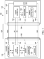
- the charger 110 includes a USB connector 111 which is adapted to receive a plug or receptacle 132 of the USB cable 130, and which provides conductive structures 151-154 for electrical connection to various conductors of the USB cable 130.
- a first conductive structure 151 provides electrical connection to a first data signal conductor of the USB cable 130, in this case a positive data signal conductor DP or D+
- a second conductive structure 152 provides electrical connection to a negative data signal conductor DN or D-
- third and fourth conductive structures 153 and 154 respectively providing electrical connection to first and second (e.g., positive and negative) power conductors VBUS and GND of the USB cable 130.
- the charger connector 111 can be any suitable connector configured to interface with a standard USB cable 130, for example, an A-type or a B-type USB cable plug or receptacle having any suitable number of connections according to relevant USB standards, where certain embodiments of the connector 111 can accommodate more than four connections, and can be adapted to receive or interface with a male connector 132 (plug) or a female connector (receptacle).
- a standard USB cable 130 for example, an A-type or a B-type USB cable plug or receptacle having any suitable number of connections according to relevant USB standards, where certain embodiments of the connector 111 can accommodate more than four connections, and can be adapted to receive or interface with a male connector 132 (plug) or a female connector (receptacle).
- the charger apparatus 110 also includes a power supply 112 coupled to supply electrical power at one of a plurality of output power levels to a connected electronic device 120 via the third and fourth conductive structures 153 and 154.
- the power supply 112 is programmable to supply output power at 5V, 12V or 20V, and may be capable of providing output current at 1A, 3A or 5A.
- the power supply 112 may implement other charging levels regarding voltage and current outputs, and may implement more or fewer combinations to provide two or more programmable output power levels.
- the charger apparatus 110 further includes a controller 114 and a memory or data store 116 storing charger capability information 117 and status information 118.
- the controller 114 can be any suitable processor, control circuit, programmable logic, logic circuit, etc., and may include interface circuitry for sending and receiving digital data signals.
- the controller 114 is coupled with the conductive structures 151 and 152 and operates in certain embodiments as a slave controller to provide charger capability information 117 representing two or more output power levels to the connected electronic device 120 using a bidirectional digital communications connection established along the DP and DN conductors of the USB cable 130 via the conductive structures 151 and 152.
- the slave controller 114 may be an electronic processor mounted on a printed circuit board, with the conductive structures 151 and 152 being implemented as conductive circuit board traces electrically connected between the slave controller 114 and the connector 111.
- One or more intervening components may be connected between the slave controller 114 and the connector 111, for example, such as filter circuit components, etc.
- the bidirectional digital communications connection is an I 2 C bus connection using the first conductive structure 151 as a serial data line (SDA) and the second conductive structure 152 as a serial clock line (SCL), with the controller 114 operating as a slave controller to exchange data with a master controller 124 of the device 120.
- the charger controller 114 may operate as a master, such as in a multi-master system.
- the charger controller 114 receives configuration information from the connected electronic device 120 using the bidirectional digital communications connection through the USB cable 130, and also selectively sets or adjusts the power supply 112 to one of the plurality of output power levels at least partially according to the configuration information.
- the illustrated charger apparatus 110 is also operative to provide status information 117 representing one or more power supply conditions to the connected electronic device 120 using the bidirectional digital communications connection, for example, to indicate a power supply overvoltage condition, overcurrent condition, and/or overtemperature condition.
- the charger 110 may include suitable diagnostic circuitry, and the controller 114 may be implemented as a programmed processor operative to assess diagnostic information pertaining to the status or operating condition of the power supply 112 and may store corresponding status information 118 in the electronic memory 116.
- This provided charger status information can be used by the intelligent electronic device 120 to selectively choose a different desired power output level and accordingly send information via the communications connection to reconfigure the charger 110.
- the controller 114 controls the power supply 112 to provide a default power output level, such as 5V and 1A for powering or charging the device 120 and selectively adjusts the output level of the power supply 112 according to configuration information received from the connected electronic device 120 via the communications connection.
- the charger 110 in certain embodiments may be operable to modify or update the charger capability information 117 based on the status information 118 or based on other inputs, for example, to remove certain voltage or current capability indications from the capabilities information 117 if the diagnostic information indicates that the power supply 112 is no longer capable of providing certain voltage and/or current levels.
- the electronic device 120 includes a USB connector 121 as well as a load 122, a controller 124, and a processor 126 with an associated electronic memory 128, and may include further circuitry such as a charger detection circuit 129 and a switching circuit as described further below in connection with Fig. 2 .
- the connector 121 is adapted for receiving a connector 134 (e.g., a plug or a receptacle) of the USB cable 130, and provides conductive structures 141-144 for electrical connection to the DP, DN, VBUS and GND conductors of the cable 130, respectively.
- the device 120 also includes a load 122 connected to the conductive structures 143 and 144, where the load 122 can be a power supply for operating various circuitry of the device 120, a chargeable battery system, or other electrical load in various embodiments.
- the device controller 124 is coupled with the conductive structures 141 and 142 for communicating with a connected charger 110, and is selectively operative to establish a bidirectional digital communications connection for exchanging data with the connected charger 110 along the DP and DN conductors of the USB cable 130.
- the device controller 124 can be any suitable analog and/or digital circuitry, and may be programmable including a processor component, programmable logic, etc. in various embodiments.
- the processor 126 is operatively coupled with the controller 124, and is programmed to use the controller 124 in order to establish a bidirectional digital communications connection or link with a connected charger 110. In certain implementations, the processor 126 initiates communications connection establishment with the controller 124, or a connected charger 110 may initiate the communications connection establishment. Any suitable process can be implemented between the controllers 114, 124 of the charger 110 and the device 120 in order to establish a bidirectional communications link along the DP and DN lines.
- the processor 126 of the device 120 obtains charger capability information 117 from the connected charger 110 via the bidirectional digital communications connection established by the controller 124, and the processor selectively configures or reconfigures the connected charger 110 using the bidirectional digital communications connection along the DP and DN conductors.
- the electronic device 120 sends a message through the communications link to the charger 110 requesting the charger capability information 117, and the controller 114 of the charger (operating as a slave) responds with a message including the requested capability information 117.
- the charger 110 provides the charging capability information 117 without prompting by the device 120. Suitable message frames and communication protocols can be used by which the charger 110 provides the capability information 117 in a format recognizable by the device 120.
- the processor 126 of the device 120 constructs and transmits a message or messages to the charger 110 via the communications link along the DP and DN lines indicating a selected charging level recognizable by the charger 110 for configuring or programming the power supply 112 accordingly.
- the controller 124 and the connected charger 110 communicate using any suitable communications protocol, including without limitation I 2 C, universal asynchronous receiver transmitter (UART), serial peripheral interface (SPI), etc.
- the configuration or reconfiguration is implemented by the processor 126 at least in part according to charger capability information 117 received from the charger 110.
- the memory 128 in this embodiment stores device charging capability information 127, which represents one or more suitable charging power levels at which power can safely be provided to the load 122.
- the device processor 126 determines one or more matches between the charger capability information 117 received from the charger 110 and the device charging capability information 127 stored in the memory 128, and selectively configures or reconfigures the charger 110 using the bidirectional digital communications connection at least in part according to identified matches.
- the processor 126 takes into account other factors in determining what configuration information to send to the charger 110, namely charger status information received from the charger 110.
- the device processor 126 may selectively reconfigure the connected charger 110 according to a slower charging match between the charger capability information 117 and the device charging capability information 127 based at least partially on any received charger status information 118. For example, if the slave controller 114 reports an overtemperature condition in the power supply 112, the device processor 126 may reconfigure the charger 110 by sending a reconfiguration message indicating a desired charging voltage level of 12V. In this example, the charger controller 114 may thereafter report clearance of the previously reported overtemperature condition, after which the device processor 126 may again reconfigure the charger 110 to resume operation at the higher power output level (e.g., 20V in this example).
- the higher power output level e.g. 20V in this example
- the electronic device 120 can intelligently facilitate safe operation of the charger 110 while expediting charging by preferentially choosing a highest power output level within the capabilities of both the charger 110 and the device 120, and selectively reducing the power output level (e.g., thereby slowing down the charging process) on an as-needed basis according to reported power supply status information 118 from the charger 110.
- This advantageous operation moreover, is not possible using charging and device equipment incapable of communicating with one another, and is also not possible using simple unidirectional communications.
- USB data lines DP and DN to implement the bidirectional digital communications connection advantageously avoids or mitigates the need for excessive circuit modifications, wherein other approaches using the power supply connection (e.g., VBUS) for communications between the charger and the device require AC coupling circuitry to interface a transmitter and a receiver at either end of the USB cable 130.
- the concepts of the present disclosure utilize the data signal conductors DP and DN to implement bidirectional communications thereby facilitating intelligent fast charging operation.
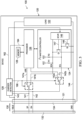
- Fig. 2 illustrates further details of an embodiment of a charger 110 and a device 120, in which an Inter-Integrated Circuit or I 2 C bus communications link is established, with the charger controller 114 implemented in a microcontroller unit (MCU) as a slave controller for the I 2 C communications, and with the device controller 124 operating as an I 2 C master controller.
- MCU microcontroller unit
- Other bidirectional digital communications links can be implemented using the DP and DN lines, including without limitation SPI, UART, etc.
- the charger 110 in the I 2 C embodiment includes a low dropout (LDO) supply 113 providing power to the slave controller 114, and the controller 114 configures the charger power supply 112 by way of a resistor array 119 to provide an adjustable setpoint to the power supply 112.
- LDO low dropout
- the charger 110 includes a variable resistor R connected between the data lines 151 and 152, where the controller 114 is configured to selectively modify the resistance value of the resistor R.
- Any suitable variable resistance circuitry can be used to implement the variable resistor R, such as a switching circuit for interconnecting various individual resistors in a series, parallel and/or a combination series/parallel configuration between the data lines 151 and 152. The resistance value may be used in certain embodiments to facilitate connection detection by the device 120 as described further below.
- the controller 114 is operatively coupled with the memory 116 which again stores the charger capabilities information 117 and may store charger status information 118 as described above. In other possible embodiments, any general-purpose I/O maybe operatively coupled with the device controller 114 for providing the charger capability information 117 to the connected device 120 representing two or more output power levels that may be implemented by the power supply 112.
- the device in this case includes a charger detection circuit 129 coupled with the data lines 141 and 142, where the detection circuit 129 provides a switching control signal 166 having a first state indicating that connection of the charger 110 has been detected, and a second state indicating that no charger 110 is connected to the device 120 via the USB connector 121.
- Any suitable detection circuitry 129 may be used in various embodiments, a non-limiting example of which is illustrated and described further below in connection with Fig. 4 .
- the device 120 in the embodiment of Fig. 2 also includes a switching circuit with switches S1 and S2 coupled to receive the switching control signal 166 from the detection circuit 129.
- the switching circuit is operative to selectively couple the first and second conductive structures 141 and 142 with the communications controller 124 when the switching control signal 166 is in the first state (i.e., when a charger 110 is connected), and to selectively decouple the first and second conductive structures 141 and 142 from the controller 124 when the switching control signal 166 is in the second state (e.g., when no charger is connected).
- an I 2 C master controller 124 including a transceiver 146 with an enable input receiving a control signal 162 from the charger detection circuit 129, by which the transceiver 146 is enabled when a connected charger 110 has been detected by the detection circuitry 129, and is disabled otherwise.
- the charger detection circuit 129 in this example provides a control signal 164 to the device processor 126, thereby notifying the processor 126 that a connected charger 110 has been detected.
- the master controller 124 also includes pull-up resistors R1 and R2, with R1 being connected between the data line (SDA) and a positive supply voltage VCC, and with R2 being connected between the serial clock line SCL and VCC to accommodate interconnection of the transceiver 146 with an open drain I 2 C bus.
- the first switch S1 is operative according to the control signal 166 to connect the first conductive structure 141 (USB DP line) to either a first data connection 141a to the processor 126 (e.g., for normal USB communications) when no charger 110 is connected, or to an I 2 C bus SDA connection 141b coupled to the controller transceiver 146 (when a charger 110 is connected to the device 120) as shown.
- S2 similarly connects the second conductive structure 142 (USB DN line) to either a second data connection 142a to the processor 126 (when no charger 110 is connected), or to an I 2 C bus serial clock (SCL) connection 142b when a connected charger 110 has been detected by the detection circuitry 129.
- USB DN line USB DN line
- the master controller 124 further includes a data transmit control transistor Q1 operated by the transceiver 146 for generating output data bits on the SDA line 141b according to a transmit control line 147 (TX), and a clock control transistor Q2 operated by a control line 148 from the transceiver 146 to provide a serial clock signal on the SCL line 142b.
- the device controller 124 is operative as a master controller to establish the bidirectional digital communications connection or link as an I 2 C bus, with the bidirectional digital communications connection using the first conductive structure 141 as a serial data line SDA and the second conductive structure 142 as a serial clock line SCL as shown.
- the charger controller 114 may be configured as a slave controller, or as a master controller, and may include suitable transceiver circuitry for sending and receiving data via the USB cable 130 according to any appropriate communications protocol.
- One possible charger detection circuit embodiment 129 as illustrated in Fig. 4 including a logic circuit 170 providing the charger detection control signals 162, 164 and 166 as described above based on detection of a connected USB charger 110.
- the charger detection circuit 129 is connected to the conductive structures 141-144, and includes a comparator 172 providing a signal to the logic circuit 170 based on comparison of the voltage at the connection 143 with a reference voltage V QTG_SESS_VLD indicating whether the VBUS line of a connected USB cable 130 has a positive voltage in excess of the reference.
- the first conductive structure 141 (DP line) is connected to switches S3-S5 controlled by the logic circuit 170.
- the switch S3 selectively connects a positive data source voltage reference V DP_SRC to the DP line 141
- the switch S4 is operative according to the logic circuit 170 to selectively connect a current source 174 to provide a current I DP_SRC to the DP line.
- the switch S5 selectively connects the line 141 with a current source 176 I DP_SINK to conduct current from the line 141 to the circuit ground (conductive structure 144) and S5 also connects the line 141 with a comparator 178 comparing the voltage at the line 141 with a data reference voltage V DAT_REF .
- the line 141 is also provided as an input to an inverter 180 whose output is provided along with the output of the comparator 178 as inputs to an AND gate 182 providing a dedicated charging port detection signal (DCP_DET) to the logic circuitry 170 as shown.
- DCP_DET dedicated charging port detection signal
- the second conductive structure 142 is connected to switches S6-S8 of the charger detection circuit 129 as shown in Fig. 4 , with the switch S6 operative according to a signal from the logic circuit 170 to selectively connect the line 142 with a data source voltage reference V DM_SRC , and a switch S8 is selectively closed by the logic circuit 170 to connect the second data line (DN) to the ground line 144 through a pull-down resistor R DM_DWN .
- the logic circuit 170 controls the switch S7 to selectively connect the line 142 with a current source 184 to conduct a sink current I DM_SINK to ground, and to a comparator circuit including a comparator 186 comparing the voltage with the data reference voltage V DAT_REF , with the comparator output providing an input to an AND gate 190 along with the output of an inverter 188 to provide a charger detection signal CHG_DET to the logic 170 as shown.
- the charger detection circuit 129 and the master controller 124 may be employed by the processor 126 according to conventional USB detection procedures to ascertain what type, if any, apparatuses connected to the device 120 via the USB cable 130 in certain embodiments.
- the device 120 may implement Battery Charging Specification 1.2 primary detection or other suitable detection technique to distinguish between a standard downstream port (SDP), a charging downstream port (CDP), an accessory charger adapter (ACA) or a dedicated charging port (DCP).
- SDP standard downstream port
- CDP charging downstream port
- ACA accessory charger adapter
- DCP dedicated charging port
- Primary detection may be implemented, for example, in which the logic circuit 170 turns on switches S3 and S7 to detect whether a DCP is connected, where USB charging standard provides that a connected DCP will short DP and DN through a resistance (R DCP_DAT , not shown), and the charger detection circuit 129 can thus detect a voltage on DN (via the comparator 186) that is close to V DP_SRC .
- the device 120 also compares the voltage at the DN line with the data reference voltage V DAT_REF , with S7 closed, and if the DN line voltage exceeds this reference, the logic circuit 170 determines that the device 120 is connected to either a DCP or a CDP.
- a connected CDP can be detected with the logic 170 closing the switches S3 and S5, and the comparator 178 comparing the voltage on the line 141 with the reference V DAT_REF to selectively generate the signal DCP_DET.
- certain implementations provide for selective establishment of the bidirectional digital communications connection or link using the DP and DN lines as discussed above if the electronic device 120 detects that a dedicated charging port 110 is connected.
- Fig. 5 illustrates a process or method 200 for powering or charging an electronic device 120 from a USB cable 130.
- the method 200 in Fig. 5 and the method 300 of Fig. 6 are illustrated and described in the form of a series of acts or events, it will be appreciated that the various methods of the disclosure are not limited by the illustrated ordering of such acts or events except as specifically set forth herein. In this regard, except as specifically provided hereinafter, some acts or events may occur in different order and/or concurrently with other acts or events apart from those illustrated and described herein, and not all illustrated steps may be required to implement a process or method in accordance with the present disclosure.
- the illustrated methods may be implemented in hardware as illustrated and described above, and/or using processor-executed software, processor-executed firmware, FPGAs, logic circuitry, etc. or combinations thereof, in order to provide the adaptive intelligent charging functionality described herein, although the present disclosure is not limited to the specifically illustrated or described applications and systems.
- the process 200 in Fig. 5 illustrates operation of the electronic device 120 beginning at 202, with the device 120 determining or detecting at 204 whether a charger (e.g., a DCP charger and one embodiment) is connected.
- a charger e.g., a DCP charger and one embodiment
- the charger detection circuit 129 can be employed as described above with respect to Fig. 4 above to determine if a charger is connected.
- the process continues at 204.
- the device 120 attempts to establish a bidirectional digital communications connection with the connected charger 110 via the DP and DN lines at 206.
- the charger detection circuit 129 asserts the switching control signal 166 to operate the switching circuit S1, S2 to operatively couple the DP and DN lines with the I 2 C master controller 124 via the connections 141b and 142b as shown in Figs. 2 and 3 .
- this provides pull-up resistors R1 and R2 between the DP and DN lines, respectively and VCC, thus using DP as an I 2 C serial data line SDA and DN as a serial clock line SCL.
- the master controller 124 issues a START condition indicating to the connected charger 110 that an address will be forthcoming.
- the master controller 124 then sends and ADDRESS corresponding to a predetermined address interpreted by the charger 110 as its own address, along with an indication that a Read operation is desired.
- the connected charger (slave) controller 114 responds with an acknowledgment, and subsequently transmits data to the master controller 124, in this case the charger capability information 117 from the charger memory 116.
- the master controller 124 of the electronic device 120 determines that the bidirectional communications connection has been established (YES at 208 in Fig. 5 ), and receives the charger capability information via the communications connection at 210.
- the device processor 126 is provided with this charger capability information 117 from the controller 124, and compares the information 117 with the locally stored device charging capability information 127 from the memory 128, and determines at 212 one or more matches between the charger information 117 and the device information 127.
- the device processor 126 selectively configures the connected charger 110 using the bidirectional digital communications connection by transmitting the ADDRESS with an indication of a Write operation, followed by a configuration packet or frame indicating to the slave controller 114 the desired power supply output level selected by the connected device 120.
- the device processor 126 preferentially selects the matching level corresponding to a fastest charging match between the charger capability information 117 and the device charging capability information 127, and transmits this to the slave controller 114 at 214 in Fig. 5 .
- the device 120 receives charging power at the configured level and monitors the communications connection for any further information from the charger 110.
- the device makes a determination as to whether any charger status information has been received (e.g., charger status information 118 in Fig. 1 ), for example, indicating an overvoltage, overcurrent and/or overtemperature or other condition in the charger power supply 112 in certain embodiments. If not (NO at 218 in Fig. 5 ), the process 200 continues at 218 with the device 120 receiving charging power at the previously configured output level. If charger status information 118 has been received from the charger 110 (YES at 218), the device 120 selectively reconfigures the charger 110 via the communications connection according to the received charger status at 220, and the process returns to charging operation at 216 with the device controller 124 continuing to monitor the DP and DN lines. In certain implementations, as discussed above, the device processor 126 selectively reconfigures the charging level at 220 to slow the charging process, for example, once an overcurrent, overvoltage and/or overtemperature condition has been indicated by the charger 110 at 218.
- charger status information 118 in Fig. 1 e.g.,
- a process 300 is illustrated for charger operation beginning at 302, with the charger providing a default level of output power (e.g., 5V at 1A) via VBUS and GND at 304 while monitoring the DP and DN lines for communications from a connected electronic device 120.
- a determination is made at 306 as to whether a communications connection has been established, and if not (NO), the charger 110 continues to provide the default voltage and current levels for charging the connected device 120.
- the charger 110 sends charger capability information 117 at 308 to the connected device 120 via the DP and DN lines, and sends charger status information 118 (if available) to the device 120 at 310.
- the charger 110 receives configuration information from the device 120 using the communications connection, with the configuration information indicating a desired power supply output level (e.g., 20V at 1A).
- the charger controller 114 selectively sets the output level of the power supply 112 according to the received configuration information, and thereafter provides that output level at 316 while again monitoring the DP and DN lines for further communications from the connected device 120.
- the charger 110 also sends any updated status information 118 to the device 120 via the communications connection at 318, for example, upon detection of a predetermined condition in the charger power supply 112 (overvoltage, overcurrent and/or overtemperature).
- the charger 110 determines whether any reconfiguration information has been received via the DP and DN connections, and otherwise (NO at 320) the process continues at 316 with the charger 110 maintaining the output at the present level while monitoring the DP and DN lines for messages from the connected device 110 and sending any updated status information 118 at 318. If reconfiguration information is received from the device 120 (YES at 320), the charger 110 selectively adjusts the output power level according to the reconfiguration information at 322, and the process 300 returns to 316 as described above.
- the presently disclosed embodiments advantageously reuse DP and DN connections of the USB cable 130 to provide a bidirectional communications bus, with general purpose or other data storage on the connected charger 110 storing charger capability information 117 for transmission to a connected electronic device 120, allowing intelligent match determination and charging speed determination by the device 120 based on the actual capabilities of the charger 110 and the device 120.
- the disclosed techniques facilitate updating the charger output level under control of the connected device 120 by providing power supply status information 118 from the charger 110, thereby facilitating adaptive adjustments to mitigate product damage and facilitate shortened charging times.
- the disclosed apparatus and techniques thus present a significant advance over dedicated charging apparatus subject to user mismatching, with the disclosed device 120 and charger 110 intelligently using capability information, supplemented with charger status information, to facilitate fast charging while mitigating component damage or stress in an automated fashion, and without the additional circuitry associated with analog inter-device communication adaptations while maintaining USB compatibility and standard compliance across multiple devices and chargers.
Landscapes
- Engineering & Computer Science (AREA)
- Power Engineering (AREA)
- Charge And Discharge Circuits For Batteries Or The Like (AREA)
- Power Sources (AREA)
Applications Claiming Priority (1)
| Application Number | Priority Date | Filing Date | Title |
|---|---|---|---|
| PCT/CN2014/083659 WO2016019498A1 (en) | 2014-08-05 | 2014-08-05 | Methods, electronic devices, and charger apparatus for quick usb charging |
Publications (3)
| Publication Number | Publication Date |
|---|---|
| EP3178007A1 EP3178007A1 (en) | 2017-06-14 |
| EP3178007A4 EP3178007A4 (en) | 2018-02-28 |
| EP3178007B1 true EP3178007B1 (en) | 2024-10-09 |
Family
ID=55262982
Family Applications (1)
| Application Number | Title | Priority Date | Filing Date |
|---|---|---|---|
| EP14899393.4A Active EP3178007B1 (en) | 2014-08-05 | 2014-08-05 | Methods, electronic devices, and charger apparatus for quick usb charging |
Country Status (5)
| Country | Link |
|---|---|
| US (2) | US10014703B2 (enExample) |
| EP (1) | EP3178007B1 (enExample) |
| JP (1) | JP6501867B2 (enExample) |
| CN (3) | CN106716389B (enExample) |
| WO (1) | WO2016019498A1 (enExample) |
Families Citing this family (44)
| Publication number | Priority date | Publication date | Assignee | Title |
|---|---|---|---|---|
| US11797469B2 (en) * | 2013-05-07 | 2023-10-24 | Snap-On Incorporated | Method and system of using USB user interface in electronic torque wrench |
| TWM487568U (zh) * | 2014-03-14 | 2014-10-01 | Samya Technology Co Ltd | 可攜式隨身碟行動電源 |
| EP3178007B1 (en) * | 2014-08-05 | 2024-10-09 | Texas Instruments Incorporated | Methods, electronic devices, and charger apparatus for quick usb charging |
| US20170244265A1 (en) | 2014-11-11 | 2017-08-24 | Guangdong Oppo Mobile Telecommunications Corp., Ltd. | Communication method, power adaptor and terminal |
| US9652351B2 (en) * | 2014-12-23 | 2017-05-16 | Intel Corporation | System to detect charger and remote host for type-C connector |
| CN104600796B (zh) * | 2014-12-30 | 2019-09-20 | 惠州Tcl移动通信有限公司 | 快速充电的移动终端及方法、系统 |
| EP3171480B1 (en) * | 2015-04-29 | 2020-07-29 | Guangdong Oppo Mobile Telecommunications Corp., Ltd. | Method for identifying types of cables, power adaptor and cable |
| EP3091633B1 (en) * | 2015-05-07 | 2018-02-07 | Richtek Technology Corporation | Adaptive power converter of mobile charger |
| US10423205B2 (en) | 2015-07-29 | 2019-09-24 | Texas Instruments Incorporated | Voltage transition control for USB power delivery sources |
| TWI591927B (zh) * | 2015-08-27 | 2017-07-11 | 新唐科技股份有限公司 | 充電方法、充電控制器及充電系統 |
| US20170187200A1 (en) * | 2015-12-28 | 2017-06-29 | Dialog Semiconductor (Uk) Limited | Charger Communication by Load Modulation |
| ES2712066T3 (es) * | 2016-01-05 | 2019-05-09 | Guangdong Oppo Mobile Telecommunications Corp Ltd | Método de carga rápida, terminal móvil y adaptador |
| US10142117B2 (en) * | 2016-04-11 | 2018-11-27 | Dell Products L.P. | Information handling system selective local and remote charger control |
| US10498167B2 (en) | 2016-06-08 | 2019-12-03 | Texas Instruments Incorporated | Multi-port power delivery |
| US10476394B2 (en) | 2016-12-28 | 2019-11-12 | Texas Instruments Incorporated | Dynamic learning of voltage source capabilities |
| JP6548273B2 (ja) * | 2017-02-17 | 2019-07-24 | Necプラットフォームズ株式会社 | 携帯機器、携帯機器の制御方法、及びプログラム |
| US20180254648A1 (en) * | 2017-03-01 | 2018-09-06 | Dialog Semiconductor (Uk) Limited | Applying Alternate Modes of USB Type-C for Fast Charging Systems |
| DE102017104994A1 (de) * | 2017-03-09 | 2018-09-13 | Krohne Messtechnik Gmbh | Verfahren zum Betreiben eines induktiven Leitfähigkeitsmessgeräts und diesbezügliches induktives Leitfähigkeitsmessgerät |
| US10741348B2 (en) * | 2017-03-30 | 2020-08-11 | Richtek Technology Corporation | Power transmission apparatus |
| JP6989308B2 (ja) * | 2017-07-06 | 2022-01-05 | ローム株式会社 | ワイヤレス送電装置およびそれを用いたワイヤレス充電器 |
| CN107706977B (zh) * | 2017-10-16 | 2021-01-08 | Oppo广东移动通信有限公司 | 一种充电电流的检测方法以及充电装置 |
| JP2020005483A (ja) * | 2018-07-02 | 2020-01-09 | ワールドピーコム株式会社 | 端末ユニット |
| CN110797924B (zh) * | 2018-08-01 | 2021-08-03 | Oppo广东移动通信有限公司 | 电池控制系统和方法、电子设备 |
| CN113258652B (zh) | 2018-08-01 | 2025-06-03 | Oppo广东移动通信有限公司 | 电池控制系统和方法、电子设备 |
| US10739541B2 (en) * | 2018-09-07 | 2020-08-11 | Corning Research & Development Corporation | Optical cable assemblies having variable output current limits |
| US10417158B1 (en) * | 2018-11-07 | 2019-09-17 | Nxp B.V. | Charger attach detection |
| TWI728363B (zh) * | 2019-05-17 | 2021-05-21 | 創惟科技股份有限公司 | 具資料存取、傳輸及電源管理的整合電子裝置及其方法 |
| CN110086230B (zh) * | 2019-05-29 | 2021-01-08 | 维沃移动通信有限公司 | 充电装置及充电方法 |
| CN110233511A (zh) * | 2019-06-20 | 2019-09-13 | 东北大学 | 一种用于多媒体外接设备的自动充电机构及方法 |
| WO2021038616A1 (ja) | 2019-08-23 | 2021-03-04 | シャープNecディスプレイソリューションズ株式会社 | ソース機器、およびソース機器の電力制御方法 |
| IT201900015306A1 (it) * | 2019-08-30 | 2021-03-02 | St Microelectronics Srl | Circuito di pilotaggio ad uscita digitale e procedimento |
| AU2021200856B2 (en) * | 2020-02-28 | 2022-12-01 | Snap-On Incorporated | Method and system of using usb user interface in electronic torque wrench |
| CN111352645B (zh) * | 2020-03-31 | 2023-08-22 | 广州昂宝电子有限公司 | 用于usb-pd充电器的固件更新方法和装置 |
| US11474579B2 (en) | 2020-04-29 | 2022-10-18 | Intel Corporation | Verified high-power transition and fast charging with pre-boot scaling |
| US11705750B2 (en) * | 2020-06-25 | 2023-07-18 | Intel Corporation | Power negotiation sequence to improve user experience and battery life |
| CN113949116B (zh) * | 2020-07-15 | 2024-05-10 | 华为技术有限公司 | 一种数据传输方法及装置 |
| CN114297127B (zh) * | 2020-07-15 | 2022-11-01 | 华为技术有限公司 | 一种基于充电线缆的数据传输方法及电子设备 |
| US12212162B2 (en) | 2020-07-15 | 2025-01-28 | Huawei Technologies Co., Ltd. | Charging cable-based data transmission method and electronic device |
| KR20220019391A (ko) * | 2020-08-10 | 2022-02-17 | 삼성전자주식회사 | 전자 장치 및 상기 전자 장치의 충전 제어 방법 |
| CN113508509A (zh) * | 2020-09-24 | 2021-10-15 | 深圳市大疆创新科技有限公司 | 充电控制方法、电路、设备及存储介质 |
| CN112671062B (zh) * | 2020-12-17 | 2025-06-13 | 维沃移动通信有限公司 | 充电控制方法及装置 |
| CN112737060B (zh) * | 2021-01-21 | 2023-09-19 | 衡阳晟达信息技术有限公司 | 一种移动终端充电控制方法、装置、终端设备及存储介质 |
| US12244160B2 (en) * | 2021-07-11 | 2025-03-04 | Harman International Industries, Incorporated | System and method for delivering power to a portable device |
| CN119995109B (zh) * | 2025-04-17 | 2025-06-27 | 江苏帝奥微电子股份有限公司 | 一种集成通信接口的线性充电电路及其控制方法 |
Citations (2)
| Publication number | Priority date | Publication date | Assignee | Title |
|---|---|---|---|---|
| EP2381571A2 (en) * | 2010-04-23 | 2011-10-26 | Apple Inc. | Charging systems with direct charging port support and extended capabilities |
| CN103208850A (zh) * | 2013-04-12 | 2013-07-17 | 惠州Tcl移动通信有限公司 | 可变充电电压的usb充电系统、充电器及智能终端 |
Family Cites Families (51)
| Publication number | Priority date | Publication date | Assignee | Title |
|---|---|---|---|---|
| KR960009369U (ko) * | 1994-08-30 | 1996-03-16 | 충전 밧데리의 과충전 방지회로 | |
| US6946817B2 (en) | 2001-03-01 | 2005-09-20 | Research In Motion Limited | System and method for powering and charging a mobile communication device |
| JP2003195985A (ja) * | 2001-12-26 | 2003-07-11 | Toshiba Corp | 電子機器システム、電子機器、周辺装置及び電源制御方法 |
| KR200269832Y1 (ko) * | 2001-12-28 | 2002-03-23 | (주)에스피에스 | 스마트 기능을 가지는 외장형 배터리팩 |
| JP2003263245A (ja) * | 2002-03-07 | 2003-09-19 | Fuji Xerox Co Ltd | Usb装置 |
| KR20050004423A (ko) * | 2003-07-02 | 2005-01-12 | 주식회사 팬택앤큐리텔 | 유에스비를 이용한 이동통신단말기의 통신 장치 |
| US7271568B2 (en) * | 2004-02-11 | 2007-09-18 | Research In Motion Limited | Battery charger for portable devices and related methods |
| US7268561B2 (en) | 2004-09-20 | 2007-09-11 | Texas Instruments Incorporated | USB attach detection for USB 1.1 and USB OTG devices |
| TWI291621B (en) | 2005-06-29 | 2007-12-21 | High Tech Comp Corp | Cradle for connecting to portable electronic apparatus |
| KR100879894B1 (ko) | 2005-10-21 | 2009-01-21 | 주식회사 엘지화학 | 무용접 방식의 전지팩 |
| US7584652B2 (en) | 2005-12-21 | 2009-09-08 | Weyerhaeuser Nr Company | Methods of rapidly simulating in-service warp distortion of a wood product and/or rapidly estimating shrinkage properties using electromagnetic energy |
| CN101111020A (zh) * | 2006-07-17 | 2008-01-23 | 英华达股份有限公司 | 可携式电子通讯装置系统 |
| US8296587B2 (en) * | 2006-08-30 | 2012-10-23 | Green Plug, Inc. | Powering an electrical device through a legacy adapter capable of digital communication |
| WO2008030398A2 (en) | 2006-09-05 | 2008-03-13 | Summit Microelectronics, Inc | Circuits and methods for controlling power in a battery operated system |
| CN100583074C (zh) * | 2007-01-12 | 2010-01-20 | 奇岩电子股份有限公司 | 可自动检测通用串行总线主机或外围设备的装置 |
| JP2008193783A (ja) * | 2007-02-02 | 2008-08-21 | Nec Corp | 充電制御方法、携帯端末および充電制御システム |
| JP2009017357A (ja) * | 2007-07-06 | 2009-01-22 | Mitsubishi Electric Corp | 通信端末及びその制御方法 |
| US8442586B2 (en) | 2008-05-08 | 2013-05-14 | Texas Instruments Incorporated | Determining USB/ISO interface and power supply voltage in mobile device |
| US8482256B2 (en) * | 2008-09-11 | 2013-07-09 | Ecosol Technologies Inc. | Portable charging power system for battery-powered devices |
| US20100070659A1 (en) * | 2008-09-17 | 2010-03-18 | Kenneth Ma | Method and system for operating and/or charging a battery powered usb device based on a usb port type |
| US7895385B2 (en) * | 2008-12-09 | 2011-02-22 | Nvidia Corporation | Establishing communication over serial buses in a slave device |
| US8880909B2 (en) | 2009-07-20 | 2014-11-04 | Texas Instruments Incorporated | Auto-detect polling for correct handshake to USB client |
| US8386814B2 (en) | 2009-07-20 | 2013-02-26 | Texas Instruments Incorporated | Continuous monitoring of a USB client for battery charging specification charging capacity |
| CN102005786B (zh) * | 2009-09-01 | 2014-08-06 | 立锜科技股份有限公司 | 充电器及具有充电器的可携式装置 |
| US8686685B2 (en) * | 2009-12-25 | 2014-04-01 | Golba, Llc | Secure apparatus for wirelessly transferring power and communicating with one or more slave devices |
| KR20110095443A (ko) * | 2010-02-19 | 2011-08-25 | (주)프랜즈커뮤니케이션 | 피사체 정보 제공 방법 및 시스템 |
| US8661268B2 (en) | 2010-02-22 | 2014-02-25 | Apple Inc. | Methods and apparatus for intelligently providing power to a device |
| KR101682386B1 (ko) * | 2010-06-29 | 2016-12-12 | 삼성전자 주식회사 | 휴대용 충전 장치 및 그의 충전 방법 및 충전 시스템 |
| TWI394973B (zh) * | 2010-09-23 | 2013-05-01 | 晨星半導體股份有限公司 | 運用於手持式電子裝置中的電池偵測器與電池偵測方法 |
| US8890469B2 (en) * | 2010-11-17 | 2014-11-18 | Texas Instruments Incorporated | Devices and methods for detecting USB devices attached to a USB charging port |
| CN102487204A (zh) * | 2010-12-03 | 2012-06-06 | 深圳富泰宏精密工业有限公司 | 充电装置 |
| US9201480B2 (en) * | 2010-12-23 | 2015-12-01 | Standard Microsystems Corporation | Method and system for determining an arbitrary charging protocol in USB charging ports |
| WO2013006753A1 (en) * | 2011-07-07 | 2013-01-10 | Voxx International Corporation | Current selectable usb charger |
| TWI481151B (zh) * | 2011-08-10 | 2015-04-11 | 創傑科技股份有限公司 | 具有整合電源管理與充電單元電路之電池供電裝置 |
| TWI437793B (zh) * | 2011-09-23 | 2014-05-11 | Quanta Comp Inc | 萬用序列匯流排供電方法及應用其之裝置端裝置及系統 |
| CN103064489B (zh) * | 2011-10-21 | 2016-03-30 | 华为终端有限公司 | 一种根据usb接口状态进行内部电路选择的方法及终端 |
| US9310868B2 (en) | 2012-04-16 | 2016-04-12 | Texas Instruments Incorporated | Charging a provider/consumer with a dead battery via USB power delivery |
| TWI452798B (zh) * | 2012-06-13 | 2014-09-11 | 晶洋微電子股份有限公司 | 通用充電偵測器與通用充電偵測方法 |
| JP2014048880A (ja) * | 2012-08-31 | 2014-03-17 | Renesas Electronics Corp | 携帯式バッテリ装置 |
| US9069540B2 (en) * | 2012-10-02 | 2015-06-30 | Dell Products L.P. | Information handling system adaptive high performance power delivery |
| JP2014102693A (ja) * | 2012-11-20 | 2014-06-05 | Nec Access Technica Ltd | 携帯端末機器及び給電方法 |
| EP2755109B1 (en) * | 2013-01-09 | 2016-03-16 | Sony Mobile Communications AB | Charging an electrical device via a data interface |
| JP5998069B2 (ja) * | 2013-01-23 | 2016-09-28 | ルネサスエレクトロニクス株式会社 | 半導体装置及び電池パック |
| US10164432B2 (en) * | 2013-02-19 | 2018-12-25 | Psikick, Inc. | Systems, methods, and apparatus for powering devices using energy from a communication bus |
| CN103427460B (zh) * | 2013-07-31 | 2016-09-07 | 华为终端有限公司 | 一种供电终端、充电控制方法及装置 |
| US10114401B2 (en) * | 2013-11-18 | 2018-10-30 | Infineon Technologies Ag | System and method for a serial bus interface |
| CN103618356B (zh) * | 2013-12-03 | 2016-10-19 | Tcl通讯(宁波)有限公司 | 一种移动终端的充电系统及其充电方法 |
| CN103746434B (zh) * | 2014-01-28 | 2016-04-06 | 广东欧珀移动通信有限公司 | 充电方法和系统 |
| CN203813481U (zh) * | 2014-04-11 | 2014-09-03 | 深圳市哈里通实业有限公司 | 一种移动电源自动识别终端充电、自适应终端otg系统 |
| EP3178007B1 (en) * | 2014-08-05 | 2024-10-09 | Texas Instruments Incorporated | Methods, electronic devices, and charger apparatus for quick usb charging |
| US10361979B2 (en) * | 2014-08-08 | 2019-07-23 | Pf Loop Inc. | Computer system and method for adding attributes to an electronic message on behalf of the message's sender |
-
2014
- 2014-08-05 EP EP14899393.4A patent/EP3178007B1/en active Active
- 2014-08-05 JP JP2017506704A patent/JP6501867B2/ja active Active
- 2014-08-05 CN CN201480080874.0A patent/CN106716389B/zh active Active
- 2014-08-05 CN CN202010181889.3A patent/CN111404219B/zh active Active
- 2014-08-05 WO PCT/CN2014/083659 patent/WO2016019498A1/en not_active Ceased
- 2014-08-05 CN CN202410696600.XA patent/CN118677057A/zh active Pending
- 2014-12-08 US US14/562,920 patent/US10014703B2/en active Active
-
2018
- 2018-05-07 US US15/972,997 patent/US11646585B2/en active Active
Patent Citations (3)
| Publication number | Priority date | Publication date | Assignee | Title |
|---|---|---|---|---|
| EP2381571A2 (en) * | 2010-04-23 | 2011-10-26 | Apple Inc. | Charging systems with direct charging port support and extended capabilities |
| CN103208850A (zh) * | 2013-04-12 | 2013-07-17 | 惠州Tcl移动通信有限公司 | 可变充电电压的usb充电系统、充电器及智能终端 |
| US20150236522A1 (en) * | 2013-04-12 | 2015-08-20 | Huizhou Tcl Mobile Communication Co., Ltd. | Usb charging system with variable charging voltage, charger and smart terminal |
Also Published As
| Publication number | Publication date |
|---|---|
| EP3178007A4 (en) | 2018-02-28 |
| JP2017525053A (ja) | 2017-08-31 |
| EP3178007A1 (en) | 2017-06-14 |
| CN111404219B (zh) | 2024-06-18 |
| JP6501867B2 (ja) | 2019-04-17 |
| US20160043586A1 (en) | 2016-02-11 |
| CN106716389B (zh) | 2020-04-10 |
| CN111404219A (zh) | 2020-07-10 |
| US11646585B2 (en) | 2023-05-09 |
| WO2016019498A1 (en) | 2016-02-11 |
| CN118677057A (zh) | 2024-09-20 |
| US10014703B2 (en) | 2018-07-03 |
| US20180254650A1 (en) | 2018-09-06 |
| CN106716389A (zh) | 2017-05-24 |
Similar Documents
| Publication | Publication Date | Title |
|---|---|---|
| US11646585B2 (en) | Methods, electronic devices, and charger apparatus for quick USB charging | |
| US9356460B2 (en) | Method and apparatus of fast battery charging with universal high power input source | |
| CN103064489B (zh) | 一种根据usb接口状态进行内部电路选择的方法及终端 | |
| US8880909B2 (en) | Auto-detect polling for correct handshake to USB client | |
| EP2381571B1 (en) | Charging systems with direct charging port support and extended capabilities | |
| US10241935B2 (en) | Portable device, cable assembly, and USB system | |
| CN108988431B (zh) | 一种多协议充电装置以及多协议充电方法 | |
| US20160105038A1 (en) | Adapter, portable electronic device and charge control method thereof | |
| JP2017525053A5 (enExample) | ||
| CN104393627A (zh) | Usb充电器、移动终端和充电控制方法 | |
| CN104393628A (zh) | Usb充电器、移动终端和充电控制方法 | |
| KR20160030261A (ko) | 전류 제한을 변경하는 장치 및 방법 | |
| EP3035200B1 (en) | Systems and methods for automatic detection of a device | |
| CN105162213A (zh) | Usb控制装置及设备 | |
| JP6679768B2 (ja) | 迅速なusb充電のための方法、電子デバイス、および充電器装置 | |
| KR102315230B1 (ko) | Usb c형 커넥터를 구비하는 전자 장치 | |
| CN215009656U (zh) | 一种检测受电设备接入供电设备的电路 | |
| CN103001261B (zh) | 广用型usb充电器 | |
| WO2016010785A1 (en) | Low-power usb host supporting a high-power usb peripheral device and methods thereof | |
| CN107706977A (zh) | 一种充电电流的检测方法以及充电装置 | |
| CN223038158U (zh) | 接口检测设备 | |
| HK1163383A (en) | Charging systems with direct charging port support and extended capabilities |
Legal Events
| Date | Code | Title | Description |
|---|---|---|---|
| STAA | Information on the status of an ep patent application or granted ep patent |
Free format text: STATUS: THE INTERNATIONAL PUBLICATION HAS BEEN MADE |
|
| PUAI | Public reference made under article 153(3) epc to a published international application that has entered the european phase |
Free format text: ORIGINAL CODE: 0009012 |
|
| STAA | Information on the status of an ep patent application or granted ep patent |
Free format text: STATUS: REQUEST FOR EXAMINATION WAS MADE |
|
| 17P | Request for examination filed |
Effective date: 20170306 |
|
| AK | Designated contracting states |
Kind code of ref document: A1 Designated state(s): AL AT BE BG CH CY CZ DE DK EE ES FI FR GB GR HR HU IE IS IT LI LT LU LV MC MK MT NL NO PL PT RO RS SE SI SK SM TR |
|
| AX | Request for extension of the european patent |
Extension state: BA ME |
|
| DAX | Request for extension of the european patent (deleted) | ||
| A4 | Supplementary search report drawn up and despatched |
Effective date: 20180126 |
|
| RIC1 | Information provided on ipc code assigned before grant |
Ipc: G06F 13/14 20060101AFI20180122BHEP |
|
| STAA | Information on the status of an ep patent application or granted ep patent |
Free format text: STATUS: EXAMINATION IS IN PROGRESS |
|
| 17Q | First examination report despatched |
Effective date: 20181023 |
|
| REG | Reference to a national code |
Ref country code: DE Ref legal event code: R079 Free format text: PREVIOUS MAIN CLASS: G06F0013140000 Ipc: H02J0007000000 Ref document number: 602014091006 Country of ref document: DE |
|
| GRAP | Despatch of communication of intention to grant a patent |
Free format text: ORIGINAL CODE: EPIDOSNIGR1 |
|
| STAA | Information on the status of an ep patent application or granted ep patent |
Free format text: STATUS: GRANT OF PATENT IS INTENDED |
|
| RIC1 | Information provided on ipc code assigned before grant |
Ipc: H02J 7/00 20060101AFI20240206BHEP |
|
| INTG | Intention to grant announced |
Effective date: 20240301 |
|
| P01 | Opt-out of the competence of the unified patent court (upc) registered |
Effective date: 20240415 |
|
| GRAS | Grant fee paid |
Free format text: ORIGINAL CODE: EPIDOSNIGR3 |
|
| GRAA | (expected) grant |
Free format text: ORIGINAL CODE: 0009210 |
|
| STAA | Information on the status of an ep patent application or granted ep patent |
Free format text: STATUS: THE PATENT HAS BEEN GRANTED |
|
| AK | Designated contracting states |
Kind code of ref document: B1 Designated state(s): AL AT BE BG CH CY CZ DE DK EE ES FI FR GB GR HR HU IE IS IT LI LT LU LV MC MK MT NL NO PL PT RO RS SE SI SK SM TR |
|
| REG | Reference to a national code |
Ref country code: GB Ref legal event code: FG4D |
|
| REG | Reference to a national code |
Ref country code: CH Ref legal event code: EP |
|
| REG | Reference to a national code |
Ref country code: DE Ref legal event code: R096 Ref document number: 602014091006 Country of ref document: DE |
|
| REG | Reference to a national code |
Ref country code: IE Ref legal event code: FG4D |
|
| REG | Reference to a national code |
Ref country code: LT Ref legal event code: MG9D |
|
| REG | Reference to a national code |
Ref country code: NL Ref legal event code: MP Effective date: 20241009 |
|
| REG | Reference to a national code |
Ref country code: AT Ref legal event code: MK05 Ref document number: 1731656 Country of ref document: AT Kind code of ref document: T Effective date: 20241009 |
|
| PG25 | Lapsed in a contracting state [announced via postgrant information from national office to epo] |
Ref country code: NL Free format text: LAPSE BECAUSE OF FAILURE TO SUBMIT A TRANSLATION OF THE DESCRIPTION OR TO PAY THE FEE WITHIN THE PRESCRIBED TIME-LIMIT Effective date: 20241009 |
|
| PG25 | Lapsed in a contracting state [announced via postgrant information from national office to epo] |
Ref country code: NL Free format text: LAPSE BECAUSE OF FAILURE TO SUBMIT A TRANSLATION OF THE DESCRIPTION OR TO PAY THE FEE WITHIN THE PRESCRIBED TIME-LIMIT Effective date: 20241009 |
|
| PG25 | Lapsed in a contracting state [announced via postgrant information from national office to epo] |
Ref country code: IS Free format text: LAPSE BECAUSE OF FAILURE TO SUBMIT A TRANSLATION OF THE DESCRIPTION OR TO PAY THE FEE WITHIN THE PRESCRIBED TIME-LIMIT Effective date: 20250209 Ref country code: PT Free format text: LAPSE BECAUSE OF FAILURE TO SUBMIT A TRANSLATION OF THE DESCRIPTION OR TO PAY THE FEE WITHIN THE PRESCRIBED TIME-LIMIT Effective date: 20250210 Ref country code: HR Free format text: LAPSE BECAUSE OF FAILURE TO SUBMIT A TRANSLATION OF THE DESCRIPTION OR TO PAY THE FEE WITHIN THE PRESCRIBED TIME-LIMIT Effective date: 20241009 |
|
| PG25 | Lapsed in a contracting state [announced via postgrant information from national office to epo] |
Ref country code: FI Free format text: LAPSE BECAUSE OF FAILURE TO SUBMIT A TRANSLATION OF THE DESCRIPTION OR TO PAY THE FEE WITHIN THE PRESCRIBED TIME-LIMIT Effective date: 20241009 |
|
| PG25 | Lapsed in a contracting state [announced via postgrant information from national office to epo] |
Ref country code: BG Free format text: LAPSE BECAUSE OF FAILURE TO SUBMIT A TRANSLATION OF THE DESCRIPTION OR TO PAY THE FEE WITHIN THE PRESCRIBED TIME-LIMIT Effective date: 20241009 |
|
| PG25 | Lapsed in a contracting state [announced via postgrant information from national office to epo] |
Ref country code: ES Free format text: LAPSE BECAUSE OF FAILURE TO SUBMIT A TRANSLATION OF THE DESCRIPTION OR TO PAY THE FEE WITHIN THE PRESCRIBED TIME-LIMIT Effective date: 20241009 |
|
| PG25 | Lapsed in a contracting state [announced via postgrant information from national office to epo] |
Ref country code: NO Free format text: LAPSE BECAUSE OF FAILURE TO SUBMIT A TRANSLATION OF THE DESCRIPTION OR TO PAY THE FEE WITHIN THE PRESCRIBED TIME-LIMIT Effective date: 20250109 |
|
| PG25 | Lapsed in a contracting state [announced via postgrant information from national office to epo] |
Ref country code: LV Free format text: LAPSE BECAUSE OF FAILURE TO SUBMIT A TRANSLATION OF THE DESCRIPTION OR TO PAY THE FEE WITHIN THE PRESCRIBED TIME-LIMIT Effective date: 20241009 Ref country code: GR Free format text: LAPSE BECAUSE OF FAILURE TO SUBMIT A TRANSLATION OF THE DESCRIPTION OR TO PAY THE FEE WITHIN THE PRESCRIBED TIME-LIMIT Effective date: 20250110 Ref country code: AT Free format text: LAPSE BECAUSE OF FAILURE TO SUBMIT A TRANSLATION OF THE DESCRIPTION OR TO PAY THE FEE WITHIN THE PRESCRIBED TIME-LIMIT Effective date: 20241009 |
|
| PG25 | Lapsed in a contracting state [announced via postgrant information from national office to epo] |
Ref country code: PL Free format text: LAPSE BECAUSE OF FAILURE TO SUBMIT A TRANSLATION OF THE DESCRIPTION OR TO PAY THE FEE WITHIN THE PRESCRIBED TIME-LIMIT Effective date: 20241009 |
|
| PG25 | Lapsed in a contracting state [announced via postgrant information from national office to epo] |
Ref country code: RS Free format text: LAPSE BECAUSE OF FAILURE TO SUBMIT A TRANSLATION OF THE DESCRIPTION OR TO PAY THE FEE WITHIN THE PRESCRIBED TIME-LIMIT Effective date: 20250109 |
|
| PG25 | Lapsed in a contracting state [announced via postgrant information from national office to epo] |
Ref country code: SM Free format text: LAPSE BECAUSE OF FAILURE TO SUBMIT A TRANSLATION OF THE DESCRIPTION OR TO PAY THE FEE WITHIN THE PRESCRIBED TIME-LIMIT Effective date: 20241009 |
|
| PG25 | Lapsed in a contracting state [announced via postgrant information from national office to epo] |
Ref country code: DK Free format text: LAPSE BECAUSE OF FAILURE TO SUBMIT A TRANSLATION OF THE DESCRIPTION OR TO PAY THE FEE WITHIN THE PRESCRIBED TIME-LIMIT Effective date: 20241009 |
|
| REG | Reference to a national code |
Ref country code: DE Ref legal event code: R097 Ref document number: 602014091006 Country of ref document: DE |
|
| PG25 | Lapsed in a contracting state [announced via postgrant information from national office to epo] |
Ref country code: EE Free format text: LAPSE BECAUSE OF FAILURE TO SUBMIT A TRANSLATION OF THE DESCRIPTION OR TO PAY THE FEE WITHIN THE PRESCRIBED TIME-LIMIT Effective date: 20241009 |
|
| PG25 | Lapsed in a contracting state [announced via postgrant information from national office to epo] |
Ref country code: RO Free format text: LAPSE BECAUSE OF FAILURE TO SUBMIT A TRANSLATION OF THE DESCRIPTION OR TO PAY THE FEE WITHIN THE PRESCRIBED TIME-LIMIT Effective date: 20241009 |
|
| PG25 | Lapsed in a contracting state [announced via postgrant information from national office to epo] |
Ref country code: SK Free format text: LAPSE BECAUSE OF FAILURE TO SUBMIT A TRANSLATION OF THE DESCRIPTION OR TO PAY THE FEE WITHIN THE PRESCRIBED TIME-LIMIT Effective date: 20241009 |
|
| PG25 | Lapsed in a contracting state [announced via postgrant information from national office to epo] |
Ref country code: CZ Free format text: LAPSE BECAUSE OF FAILURE TO SUBMIT A TRANSLATION OF THE DESCRIPTION OR TO PAY THE FEE WITHIN THE PRESCRIBED TIME-LIMIT Effective date: 20241009 |
|
| PG25 | Lapsed in a contracting state [announced via postgrant information from national office to epo] |
Ref country code: IT Free format text: LAPSE BECAUSE OF FAILURE TO SUBMIT A TRANSLATION OF THE DESCRIPTION OR TO PAY THE FEE WITHIN THE PRESCRIBED TIME-LIMIT Effective date: 20241009 |
|
| PLBE | No opposition filed within time limit |
Free format text: ORIGINAL CODE: 0009261 |
|
| STAA | Information on the status of an ep patent application or granted ep patent |
Free format text: STATUS: NO OPPOSITION FILED WITHIN TIME LIMIT |
|
| PG25 | Lapsed in a contracting state [announced via postgrant information from national office to epo] |
Ref country code: SE Free format text: LAPSE BECAUSE OF FAILURE TO SUBMIT A TRANSLATION OF THE DESCRIPTION OR TO PAY THE FEE WITHIN THE PRESCRIBED TIME-LIMIT Effective date: 20241009 |
|
| 26N | No opposition filed |
Effective date: 20250710 |
|
| PGFP | Annual fee paid to national office [announced via postgrant information from national office to epo] |
Ref country code: DE Payment date: 20250724 Year of fee payment: 12 |
|
| PGFP | Annual fee paid to national office [announced via postgrant information from national office to epo] |
Ref country code: GB Payment date: 20250725 Year of fee payment: 12 |
|
| PGFP | Annual fee paid to national office [announced via postgrant information from national office to epo] |
Ref country code: FR Payment date: 20250723 Year of fee payment: 12 |
|
| REG | Reference to a national code |
Ref country code: CH Ref legal event code: H13 Free format text: ST27 STATUS EVENT CODE: U-0-0-H10-H13 (AS PROVIDED BY THE NATIONAL OFFICE) Effective date: 20260324 |
|
| PG25 | Lapsed in a contracting state [announced via postgrant information from national office to epo] |
Ref country code: MC Free format text: LAPSE BECAUSE OF FAILURE TO SUBMIT A TRANSLATION OF THE DESCRIPTION OR TO PAY THE FEE WITHIN THE PRESCRIBED TIME-LIMIT Effective date: 20241009 |
|
| PG25 | Lapsed in a contracting state [announced via postgrant information from national office to epo] |
Ref country code: LU Free format text: LAPSE BECAUSE OF NON-PAYMENT OF DUE FEES Effective date: 20250805 |
|
| PG25 | Lapsed in a contracting state [announced via postgrant information from national office to epo] |
Ref country code: CH Free format text: LAPSE BECAUSE OF NON-PAYMENT OF DUE FEES Effective date: 20250831 |