EP3177353B1 - Adaptateurs des voies respiratoires et systèmes de cathéter d'aspiration - Google Patents
Adaptateurs des voies respiratoires et systèmes de cathéter d'aspiration Download PDFInfo
- Publication number
- EP3177353B1 EP3177353B1 EP15754329.9A EP15754329A EP3177353B1 EP 3177353 B1 EP3177353 B1 EP 3177353B1 EP 15754329 A EP15754329 A EP 15754329A EP 3177353 B1 EP3177353 B1 EP 3177353B1
- Authority
- EP
- European Patent Office
- Prior art keywords
- valve
- port
- suction catheter
- suction
- airway adapter
- Prior art date
- Legal status (The legal status is an assumption and is not a legal conclusion. Google has not performed a legal analysis and makes no representation as to the accuracy of the status listed.)
- Active
Links
- 238000009423 ventilation Methods 0.000 claims description 68
- 230000037361 pathway Effects 0.000 claims description 64
- 238000005336 cracking Methods 0.000 claims description 41
- 230000007246 mechanism Effects 0.000 claims description 30
- 230000014759 maintenance of location Effects 0.000 claims description 7
- 239000012530 fluid Substances 0.000 description 96
- 238000000034 method Methods 0.000 description 56
- 230000000241 respiratory effect Effects 0.000 description 51
- 230000008878 coupling Effects 0.000 description 29
- 238000010168 coupling process Methods 0.000 description 29
- 238000005859 coupling reaction Methods 0.000 description 29
- 239000000463 material Substances 0.000 description 29
- 238000004140 cleaning Methods 0.000 description 27
- 238000005516 engineering process Methods 0.000 description 22
- 230000006870 function Effects 0.000 description 13
- 230000000717 retained effect Effects 0.000 description 13
- 238000007789 sealing Methods 0.000 description 13
- 239000000243 solution Substances 0.000 description 13
- 230000006835 compression Effects 0.000 description 11
- 238000007906 compression Methods 0.000 description 11
- 238000003780 insertion Methods 0.000 description 11
- 230000037431 insertion Effects 0.000 description 11
- 230000008569 process Effects 0.000 description 11
- 210000003813 thumb Anatomy 0.000 description 11
- 238000004891 communication Methods 0.000 description 10
- 230000000670 limiting effect Effects 0.000 description 10
- 230000028327 secretion Effects 0.000 description 10
- 210000003097 mucus Anatomy 0.000 description 9
- 230000029058 respiratory gaseous exchange Effects 0.000 description 8
- 239000000853 adhesive Substances 0.000 description 6
- 230000001070 adhesive effect Effects 0.000 description 6
- 230000004888 barrier function Effects 0.000 description 6
- 230000008901 benefit Effects 0.000 description 6
- 229920001971 elastomer Polymers 0.000 description 6
- 238000004088 simulation Methods 0.000 description 6
- FAPWRFPIFSIZLT-UHFFFAOYSA-M Sodium chloride Chemical compound [Na+].[Cl-] FAPWRFPIFSIZLT-UHFFFAOYSA-M 0.000 description 5
- 238000013459 approach Methods 0.000 description 5
- 230000000881 depressing effect Effects 0.000 description 5
- 239000004033 plastic Substances 0.000 description 5
- 229920003023 plastic Polymers 0.000 description 5
- 239000011780 sodium chloride Substances 0.000 description 5
- 206010036790 Productive cough Diseases 0.000 description 4
- QVGXLLKOCUKJST-UHFFFAOYSA-N atomic oxygen Chemical compound [O] QVGXLLKOCUKJST-UHFFFAOYSA-N 0.000 description 4
- 238000013461 design Methods 0.000 description 4
- 238000010586 diagram Methods 0.000 description 4
- 230000000694 effects Effects 0.000 description 4
- 239000000806 elastomer Substances 0.000 description 4
- 210000003811 finger Anatomy 0.000 description 4
- 238000005259 measurement Methods 0.000 description 4
- 239000001301 oxygen Substances 0.000 description 4
- 229910052760 oxygen Inorganic materials 0.000 description 4
- 210000002345 respiratory system Anatomy 0.000 description 4
- 238000007790 scraping Methods 0.000 description 4
- 210000003802 sputum Anatomy 0.000 description 4
- 208000024794 sputum Diseases 0.000 description 4
- 230000009286 beneficial effect Effects 0.000 description 3
- 230000000903 blocking effect Effects 0.000 description 3
- 239000013536 elastomeric material Substances 0.000 description 3
- 238000001125 extrusion Methods 0.000 description 3
- 238000005304 joining Methods 0.000 description 3
- 210000004072 lung Anatomy 0.000 description 3
- 229910052751 metal Inorganic materials 0.000 description 3
- 229920002635 polyurethane Polymers 0.000 description 3
- 239000004814 polyurethane Substances 0.000 description 3
- 239000012858 resilient material Substances 0.000 description 3
- 238000003466 welding Methods 0.000 description 3
- 239000004721 Polyphenylene oxide Substances 0.000 description 2
- 150000001875 compounds Chemical class 0.000 description 2
- 230000006378 damage Effects 0.000 description 2
- 230000007423 decrease Effects 0.000 description 2
- 238000002347 injection Methods 0.000 description 2
- 239000007924 injection Substances 0.000 description 2
- 230000013011 mating Effects 0.000 description 2
- 238000005399 mechanical ventilation Methods 0.000 description 2
- 239000002184 metal Substances 0.000 description 2
- 239000007769 metal material Substances 0.000 description 2
- 230000004048 modification Effects 0.000 description 2
- 238000012986 modification Methods 0.000 description 2
- 230000002093 peripheral effect Effects 0.000 description 2
- 229920000570 polyether Polymers 0.000 description 2
- 229920001296 polysiloxane Polymers 0.000 description 2
- 229920006264 polyurethane film Polymers 0.000 description 2
- 230000002829 reductive effect Effects 0.000 description 2
- 230000000284 resting effect Effects 0.000 description 2
- 239000000126 substance Substances 0.000 description 2
- 230000007704 transition Effects 0.000 description 2
- 238000012800 visualization Methods 0.000 description 2
- RYGMFSIKBFXOCR-UHFFFAOYSA-N Copper Chemical compound [Cu] RYGMFSIKBFXOCR-UHFFFAOYSA-N 0.000 description 1
- 102000002508 Peptide Elongation Factors Human genes 0.000 description 1
- 108010068204 Peptide Elongation Factors Proteins 0.000 description 1
- NIXOWILDQLNWCW-UHFFFAOYSA-N acrylic acid group Chemical group C(C=C)(=O)O NIXOWILDQLNWCW-UHFFFAOYSA-N 0.000 description 1
- 230000009471 action Effects 0.000 description 1
- 230000003213 activating effect Effects 0.000 description 1
- 230000002411 adverse Effects 0.000 description 1
- 238000013019 agitation Methods 0.000 description 1
- 230000000712 assembly Effects 0.000 description 1
- 238000000429 assembly Methods 0.000 description 1
- 239000011324 bead Substances 0.000 description 1
- 239000008280 blood Substances 0.000 description 1
- 210000004369 blood Anatomy 0.000 description 1
- 238000006243 chemical reaction Methods 0.000 description 1
- 230000001010 compromised effect Effects 0.000 description 1
- 238000002591 computed tomography Methods 0.000 description 1
- 230000001276 controlling effect Effects 0.000 description 1
- 229910052802 copper Inorganic materials 0.000 description 1
- 239000010949 copper Substances 0.000 description 1
- 230000001934 delay Effects 0.000 description 1
- 230000005489 elastic deformation Effects 0.000 description 1
- 239000007789 gas Substances 0.000 description 1
- 230000006872 improvement Effects 0.000 description 1
- 238000010348 incorporation Methods 0.000 description 1
- 208000014674 injury Diseases 0.000 description 1
- 230000003434 inspiratory effect Effects 0.000 description 1
- 230000003993 interaction Effects 0.000 description 1
- 230000002452 interceptive effect Effects 0.000 description 1
- 238000002372 labelling Methods 0.000 description 1
- 239000007788 liquid Substances 0.000 description 1
- 230000007774 longterm Effects 0.000 description 1
- 239000000314 lubricant Substances 0.000 description 1
- 230000000813 microbial effect Effects 0.000 description 1
- 230000000877 morphologic effect Effects 0.000 description 1
- 230000007935 neutral effect Effects 0.000 description 1
- 239000002245 particle Substances 0.000 description 1
- 239000004417 polycarbonate Substances 0.000 description 1
- 229920000515 polycarbonate Polymers 0.000 description 1
- 230000001737 promoting effect Effects 0.000 description 1
- 238000002601 radiography Methods 0.000 description 1
- 230000001105 regulatory effect Effects 0.000 description 1
- 230000004202 respiratory function Effects 0.000 description 1
- 230000004044 response Effects 0.000 description 1
- 239000011435 rock Substances 0.000 description 1
- 230000001953 sensory effect Effects 0.000 description 1
- 238000007711 solidification Methods 0.000 description 1
- 230000008023 solidification Effects 0.000 description 1
- 230000000087 stabilizing effect Effects 0.000 description 1
- 238000004381 surface treatment Methods 0.000 description 1
- 238000001356 surgical procedure Methods 0.000 description 1
- 239000012815 thermoplastic material Substances 0.000 description 1
- 238000013519 translation Methods 0.000 description 1
- 230000008733 trauma Effects 0.000 description 1
- 230000000472 traumatic effect Effects 0.000 description 1
- 230000000007 visual effect Effects 0.000 description 1
Images


Classifications
-
- A—HUMAN NECESSITIES
- A61—MEDICAL OR VETERINARY SCIENCE; HYGIENE
- A61M—DEVICES FOR INTRODUCING MEDIA INTO, OR ONTO, THE BODY; DEVICES FOR TRANSDUCING BODY MEDIA OR FOR TAKING MEDIA FROM THE BODY; DEVICES FOR PRODUCING OR ENDING SLEEP OR STUPOR
- A61M16/00—Devices for influencing the respiratory system of patients by gas treatment, e.g. mouth-to-mouth respiration; Tracheal tubes
- A61M16/04—Tracheal tubes
- A61M16/0463—Tracheal tubes combined with suction tubes, catheters or the like; Outside connections
-
- A—HUMAN NECESSITIES
- A61—MEDICAL OR VETERINARY SCIENCE; HYGIENE
- A61M—DEVICES FOR INTRODUCING MEDIA INTO, OR ONTO, THE BODY; DEVICES FOR TRANSDUCING BODY MEDIA OR FOR TAKING MEDIA FROM THE BODY; DEVICES FOR PRODUCING OR ENDING SLEEP OR STUPOR
- A61M1/00—Suction or pumping devices for medical purposes; Devices for carrying-off, for treatment of, or for carrying-over, body-liquids; Drainage systems
- A61M1/71—Suction drainage systems
- A61M1/74—Suction control
- A61M1/741—Suction control with means for varying suction manually
- A61M1/7413—Suction control with means for varying suction manually by changing the cross-section of the line
-
- A—HUMAN NECESSITIES
- A61—MEDICAL OR VETERINARY SCIENCE; HYGIENE
- A61M—DEVICES FOR INTRODUCING MEDIA INTO, OR ONTO, THE BODY; DEVICES FOR TRANSDUCING BODY MEDIA OR FOR TAKING MEDIA FROM THE BODY; DEVICES FOR PRODUCING OR ENDING SLEEP OR STUPOR
- A61M16/00—Devices for influencing the respiratory system of patients by gas treatment, e.g. mouth-to-mouth respiration; Tracheal tubes
- A61M16/08—Bellows; Connecting tubes ; Water traps; Patient circuits
- A61M16/0816—Joints or connectors
- A61M16/0825—Joints or connectors with ball-sockets
-
- A—HUMAN NECESSITIES
- A61—MEDICAL OR VETERINARY SCIENCE; HYGIENE
- A61M—DEVICES FOR INTRODUCING MEDIA INTO, OR ONTO, THE BODY; DEVICES FOR TRANSDUCING BODY MEDIA OR FOR TAKING MEDIA FROM THE BODY; DEVICES FOR PRODUCING OR ENDING SLEEP OR STUPOR
- A61M16/00—Devices for influencing the respiratory system of patients by gas treatment, e.g. mouth-to-mouth respiration; Tracheal tubes
- A61M16/08—Bellows; Connecting tubes ; Water traps; Patient circuits
- A61M16/0816—Joints or connectors
- A61M16/0833—T- or Y-type connectors, e.g. Y-piece
-
- A—HUMAN NECESSITIES
- A61—MEDICAL OR VETERINARY SCIENCE; HYGIENE
- A61M—DEVICES FOR INTRODUCING MEDIA INTO, OR ONTO, THE BODY; DEVICES FOR TRANSDUCING BODY MEDIA OR FOR TAKING MEDIA FROM THE BODY; DEVICES FOR PRODUCING OR ENDING SLEEP OR STUPOR
- A61M16/00—Devices for influencing the respiratory system of patients by gas treatment, e.g. mouth-to-mouth respiration; Tracheal tubes
- A61M16/20—Valves specially adapted to medical respiratory devices
- A61M16/208—Non-controlled one-way valves, e.g. exhalation, check, pop-off non-rebreathing valves
-
- A—HUMAN NECESSITIES
- A61—MEDICAL OR VETERINARY SCIENCE; HYGIENE
- A61M—DEVICES FOR INTRODUCING MEDIA INTO, OR ONTO, THE BODY; DEVICES FOR TRANSDUCING BODY MEDIA OR FOR TAKING MEDIA FROM THE BODY; DEVICES FOR PRODUCING OR ENDING SLEEP OR STUPOR
- A61M39/00—Tubes, tube connectors, tube couplings, valves, access sites or the like, specially adapted for medical use
- A61M39/22—Valves or arrangement of valves
-
- A—HUMAN NECESSITIES
- A61—MEDICAL OR VETERINARY SCIENCE; HYGIENE
- A61M—DEVICES FOR INTRODUCING MEDIA INTO, OR ONTO, THE BODY; DEVICES FOR TRANSDUCING BODY MEDIA OR FOR TAKING MEDIA FROM THE BODY; DEVICES FOR PRODUCING OR ENDING SLEEP OR STUPOR
- A61M2205/00—General characteristics of the apparatus
- A61M2205/27—General characteristics of the apparatus preventing use
- A61M2205/276—General characteristics of the apparatus preventing use preventing unwanted use
-
- A—HUMAN NECESSITIES
- A61—MEDICAL OR VETERINARY SCIENCE; HYGIENE
- A61M—DEVICES FOR INTRODUCING MEDIA INTO, OR ONTO, THE BODY; DEVICES FOR TRANSDUCING BODY MEDIA OR FOR TAKING MEDIA FROM THE BODY; DEVICES FOR PRODUCING OR ENDING SLEEP OR STUPOR
- A61M2205/00—General characteristics of the apparatus
- A61M2205/58—Means for facilitating use, e.g. by people with impaired vision
- A61M2205/583—Means for facilitating use, e.g. by people with impaired vision by visual feedback
- A61M2205/585—Means for facilitating use, e.g. by people with impaired vision by visual feedback having magnification means, e.g. magnifying glasses
Definitions
- the present disclosure generally relates to airway adapters, suction catheter systems, and more particularly to airway adapter assemblies, suction catheters, closed suction catheter sheaths, suction control valves, and methods of using the same.
- Ventilators and related breathing circuits may be used to assist in patient breathing.
- a patient may be connected to a ventilator to provide respiratory gases to the patient.
- the ventilation source may be connected into the patient's respiratory tract via an artificial airway, such as a tracheostomy tube, endotracheal tube, etc.
- an artificial airway such as a tracheostomy tube, endotracheal tube, etc.
- caregivers desire the ability to introduce instruments and/or materials into the breathing circuit, for example, to insert instruments for visualization or related procedures, or to aspirate fluid or secretions from the patient's airway.
- suction catheters and suction valves may be used by caregivers in closed and open suction catheter systems to aspirate fluid or secretions (e.g., mucus, secretions, blood, foreign particles, etc.) from the patient's airway.
- WO2010014735 (A1 ) discloses an adapter assembly including a manifold and a valve assembly.
- the valve assembly includes a seat and a valve body having a circular base and a wall.
- the wall extends from a trailing side of the base to form a dome-like shape terminating at an end at which a slit is formed, with the wall defining opposing sealing edges at the slit.
- the seat has an upper circumferential surface and a lower, circumferential surface.
- the upper surface engages a leading side of the base, whereas the lower surface engages a trailing side. At least one of the upper and lower surfaces forms a segment of increased height.
- the valve body is disposed across a passageway of the manifold, with the slit providing a selectively openable path. A force imparted by the segment of increased height flexes the base and biases the sealing edges into engagement.
- WO2010052241 (A1 ) concerns a respiratory suction system for providing ventilation of a patient's respiratory tract, the system comprising an elongated catheter with a distal end, a manifold defining a flow path in a ventilator circuit and comprising access means allowing the catheter to be advanced through the manifold and into a respiratory tract of a patient, the access means comprising a valve which is openable in response to the advancement of the catheter through the valve and into the flow path, wherein the valve comprises a proximal end has an annular outer flange section, a distal end and a tubular body extending between the proximal end and the distal end, the tubular body comprising a plurality of valve members extending from the annular flange section to the distal end which has end surfaces wherein a plurality of radial slits are provided, extending from the centre towards the periphery and thereby separating the valve members at the distal end.
- WO2005094925 discloses a patient ventilating and aspirating system that has a suction tube and connector for connecting to a catheter mount that has a sealed passageway.
- the catheter mount passageway is sealed with an elastomeric seal including a perforation or slit.
- a connector with a piercing member is associated with the suction tube. When the connector is attached to the catheter mount the piercing member pierces the seal such that the suction tube can pass through the connector and catheter mount.
- US2013144268 discloses a sealing vale cover used in a sputum suction pipe, which is mounted in a sputum suction pipe, which includes a valve body and an elastic contractible cover.
- the valve body has a hollow interior and an open end.
- the elastic contractible cover seals the other end of the valve body.
- the inner wall surface of the elastic contractible cover is provided with a contact rib.
- the contact rib extends radially and outwardly from the top of an inner wall surface of the elastic contractible cover.
- the contact rib is formed with an arc-shaped surface on its protruding portion.
- WO0015276 (A1 ) refers to an improved respiratory suction apparatus catheter, which includes a manifold for attachment to the distal hub of an endotracheal tube to form a ventilation circuit, a catheter tube which is displaceable through the manifold, into the endotracheal tube to suction secretions from the tube and lungs, and a valve mechanism disposed adjacent the ventilation circuit to minimize the draw of air from the ventilation circuit of a patient while the catheter is being cleaned.
- US2013312755 (A1 ) provides a suction device having a rotary switch.
- a main body of the suction device is provided with a patient-end connector, an oxygen supply connector, a suction connector, a cleaning connector and a connecting portion.
- the rotary switch is assembled with the connecting portion and can be switched between a first position and a second position.
- the rotary switch is provided with two opposite suction holes. When the rotary switch is located in the first position, the two suction holes are aligned with the patient-end connector and the suction connector to thereby communicate the patient-end connector with the suction connector. When the rotary switch is located in the second position, the communication between the patient-end connector and the suction connector is shut off.
- US2013312759 discloses an airtight suction device and a rotary switch thereof, the airtight suction device includes a main body having a communication space and a plurality of connectors. These connectors include a suction connector, a respiratory connector, a cleaning connector, and a control valve connector.
- the rotary switch is provided on the control valve connector and includes a rotary cover and a hollow post.
- the hollow post has a peripheral wall and a blocking piece.
- the peripheral wall is provided with a pair of suction holes.
- the blocking piece is provided with a ventilation hole for allowing external air to flow into the suction holes.
- US2013312756 discloses an air supply assembly of an airtight suction device, which includes: a tubular body, an oxygen supply manifold in communication with the tubular body; a scraper fixed in the tubular body; and an air supply unit provided in the tubular body and located between the oxygen supply manifold and the scraper.
- An airtight suction device can further includes a tubular body, an oxygen supply manifold, a first scraper, a second scraper, and an air supply unit.
- WO2007146613 refers to a closed suction catheter, which includes a valve assembly and a manifold. A catheter tube is attached to the valve assembly and slidably secured within the manifold.
- the closed suction catheter may include one or more features for promoting an effective, safe, and efficient process for suctioning mucus and other fluids from a patient's lungs, and for cleaning the various components of the catheter system.
- the closed suction catheter may include a tube wiper having a reinforced leading ridge and/or an internal ledge for efficiently wiping the catheter tube.
- the valve assembly may include a locking mechanism having a slider unit, a cam arm, and/or ribs that engage openings in the slider unit for maintaining a valve stem in proper alignment and an actuator on the valve assembly in a locked position.
- the closed suction catheter may include several other features, as well.
- an airway adapter assembly may comprise a connector body portion having a first end and a second end, the connector body portion defining an elongate cavity having an axial center between the first and the second end; a valve coupled to the second end of the connector body portion, the valve comprising an outer rim section configured to engage with a valve retention structure and an inner resiliently flexible diaphragm section integrally connected to the outer rim section, the inner resiliently flexible diaphragm section comprising a plurality of valve segments defined by one or more slits, wherein one or more of the valve segments include one or more first regions and one or more second regions, wherein a primary seal is formed by the plurality of valve segments, and a secondary seal is formed by an arrangement of the one or more first regions of the plurality of the valve segments, and wherein the secondary seal has a first cracking pressure, and the primary seal has a second cracking pressure different from the first cracking pressure
- a closed suction catheter system may comprise the airway adapter assembly, a suction control valve assembly comprising a housing having an interior cavity of the housing, a rigid tubular section coupled to the housing and having at least a portion of the rigid tubular section disposed within the interior cavity of the housing, the rigid tubular section having a first end, a second end, a pathway extending between the first end and the second end, and a pathway access opening arranged between the first end and the second end, an elastomeric valve member being coupled to and enclosing the pathway access opening of the rigid tubular section, and a pivotable actuator structure having a lever portion coupled to the elastomeric valve member; and a closed suction catheter sheath comprising a catheter and a flexible sleeve for enveloping the catheter, wherein the catheter is fixedly attached to the suction control valve assembly.
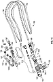
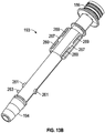
- FIGS. 1A-1C illustrate examples of a closed suction catheter system.
- closed catheter suction system 10 may comprise an airway adapter 100 having a multi-purpose valve (e.g., a peak inspiratory pressure valve having multiple seals and associated cracking pressures).
- airway adapter 100 may have a manifold-type body providing three or more fluidly connectable ports including, but not limited to, a ventilator port, a respiratory port, and an access port.
- Airway adapter 100 may be coupled to artificial airway 165, for example, at a respiratory port 160 of the airway adapter 100.
- the respiratory port 160 may include an annular swivel connector 162, allowing the multiple-port airway adapter 100 to rotate, with respect to the swivel connector 162, about a fluid pathway axis.
- Airway adapter 1 00 may be further coupled to airway adapter coupler 170, for example, at an access port of the airway adapter 100.
- a suction catheter, tubing, or other medical implement may be inserted through airway adapter coupler 170 and into the access port 110 of the airway adapter 100.
- airway adapter coupler 170 can be configured to receive various medical implements, such as but not limited to, a suction catheter included in closed suction catheter sheath 180.
- closed suction catheter sheath 180 may be coupled to airway adapter coupler 170 via capture ring 188 using, for example, an interference fitting, threaded surfaces, and/or a compression coupling.
- Closed suction catheter sheath 180 may be further coupled to suction valve 190 via capture ring 186, for example.
- suction valve 190 may be coupled to a suction source 195.
- closed suction catheter system may include suction control valve 190, suction catheter sheath 180, airway adapter coupler 170, and airway adapter 100. It is to be understood that the certain components may be omitted, included and/or combined with other components in various embodiments and implementations.
- airway adapter coupler 170 may be integrated with suction catheter sheath 180, and in some embodiments, adapter coupler 170 may be integrated with connector body 111 of airway adapter 1 00. Additionally, flush port 116 (or wash port) may be disposed on adapter coupler 170 instead of airway adapter 100, in accordance with some embodiments.
- wash port coupling assembly 216 may be configured to be removably coupled to flush port 116.
- suction catheter sheath 180 may be fixably coupled to suction control valve 190.
- suction catheter 185 may be configured without sleeve 182 for use with airway adapter 100 and/or suction control valve 190 (e.g., an open suction catheter system).
- FIG. 1D illustrates an example of a closed suction catheter system in use.
- Reference to the example closed catheter system described and illustrated in FIGS. 1A-1C is made to provide context for FIGS. 1A-1C as well as the other figures and the various aspects of the present disclosure.
- Closed suction catheter system 10 enables caregiver 11 to perform respiratory-related procedure on a patient 13.
- caregiver 11 may insert instruments for visualization or related procedures, or to aspirate fluid or secretions from the patient's airway.
- airway adapter 100 can be assembled to a breathing circuit with a ventilator fluidly connected to the ventilator port and the artificial airway 165 fluidly connected to the respiratory port of the airway adapter 100 and inserted into the airway of the patient 13.
- the patient 13 may be protected from loss of airway pressure during various procedures performed by the caregiver 11, such as changing-out of a contaminated or malfunctioning suction catheter sheath or to insert another airway instrument or medical implement into the artificial airway 165.
- airway adapter 100 provides a breachable seal between the access port of the airway adapter 100 and the ventilation and respiratory ports so that fluid pressures required to maintain ventilation of the patient 13 are not lost via the access port during normal operation. It is to be appreciated that airway adapter 100 can be beneficial with patients requiring long-term mechanical ventilation and multiple respiratory-related procedures, for example, by enabling repeated connections of the suction catheter simultaneously with the breathing circuit.
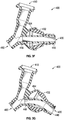
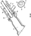
- FIGS. 2A-2K provide perspective and plan views of an example of a multiple-port airway adapter.
- various aspects of airway adapter 100 are illustrated herein.
- aspects of airway adapter 100 including, but not limited to, an airway adapter coupler 170, lens 150, ventilator port 130, and swivel connector 162 are illustrated in FIGS. 2A-2K .
- airway adapter 100 may include a wash port coupling assembly (e.g., wash port coupling assembly 216 in the example of FIG. 1C ) comprising a wash port valve assembly 600, tubular connector, and elbow connector.
- wash port valve assembly may comprise a multi-part valve housing and an elastomeric valve disposed within the multi-part valve housing.
- Multi-part valve housing may be formed from a valve body cap portion and a valve body base portion.
- each of the valve body cap portion, valve body base portion, and elastomeric valve may be formed from different material and/or similar materials having different characteristics and properties.
- one or both of the valve body cap portion and valve body base portion may be substantially rigid and generally cylindrically shaped.
- articulation of ventilator port 130 can be seen in the illustrations of FIGS. 2G-2K , for example.
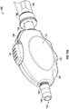
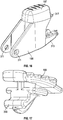
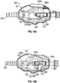
- FIGS. 2L-2S provide perspective and plan views of an example of a suction control valve.
- various aspects of suction control valve 190 are illustrated herein.
- aspects of suction control valve 190 including, but not limited to, housing 191, button 197, lock 199, and arcuate detents 251 are illustrated in FIGS. 2L-2S .
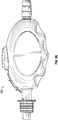
- FIGS. 3A-3C illustrate an example of a multiple-port airway adapter.
- airway adapter 100 may comprise connector body 111 having first end 113 configured to provide an access port 110 and second end 119.
- Connector body 111 may also include flush port 116 having a barbed surface 118 for engagement with certain implements such as caps, tubes, solution nozzles and the like (e.g., wash port coupling assembly 216).
- An elongate cavity 115 may be defined within the connector body 111 between the first end 113 and the second end 119.
- the flush port 116 is in fluid communication with the connector body to provide cleaning operations to be described in detail herein.
- the elongate cavity 115 has an axial center 101 that extends throughout the interior of the connector body 111 between the first end 113 and the second end 119.
- the axial center 101 may extend through other portions of the airway adapter 100, such as a tubular portion 133 of ventilator base 131 and respiratory conduit 161.
- connector body 111 may include lens 150 thereby providing magnified views into the elongate cavity 115 of the connector body 111.
- These magnified views may be beneficial, for example, so that a caregiver can read measurement indicators or other information provided on a suction catheter, tubing, or other medical implement that may be inserted through the access port 110.
- a measurement reading on a 6 French tracheostomy-length catheter in a dimly lit neonatal-care room may be performed with ease and precision with airway adapter 100 comprising lens 150.
- Valve 120 is positioned in airway adapter 100 to perform various function associated with the operation thereof.
- Valve 120 comprises a rim 123 having a first or leading edge 122 proximal to the first end 113 of connector body 111 and a second or trailing edge 124 distal from the first end 113.
- valve 120 may be retained within the airway adapter 100 by a valve seat structure.
- the valve seat structure may be formed by a fused junction between connector body 111 and a tubular portion 133 of ventilation base 131.
- the valve seat structure may comprise an upper circumferential surface 112 and a lower circumferential surface 114.
- Valve 120 may be positioned in the valve seat such that the upper circumferential surface 112 engages the leading edge 122 of the valve 120 and the lower circumferential surface 114 engages the trailing edge 124 of the valve 120.
- other valve seat structures are contemplated, for example, a rim receiving member within the connector body 111 proximal to the second end 119.
- Airway adapter 100 may further comprise an articulable ventilator port 130 projecting from ventilation base 131.
- the ventilator port 130 is coupled to the ventilation chamber 135 and fluid pathway through a ball 132 and socket 134 connection.
- the first end of the ventilator port 130 may comprise the ball 132 portion of the articulable connection, while the socket 134 portion of the articulable connection may be disposed on the airway adapter 100 between the respiratory port 160 and the access port 110.
- the ball 132 and socket 134 connection causes the ventilator port 130 to be articulable.
- the ventilator port 130 can articulate (e.g., move, pivot, rotate, swivel, tilt, etc.) about a pivot point or one or more axes.
- the ventilator port 130 can articulate about a joint or a joining portion.
- the ventilator port 130 may be retained in the socket 134 by a capture ring 140.
- the capture ring 140 is disposed around the ventilator port 130 such that the ball 132 is retained in the socket 134 with the ventilator port 130 distally projecting from a fluid pathway. Because the capture ring 140 comprises at least a portion of an inner diameter that is less than the outer diameter of the ball 132, the ball 132 is firmly retained within the socket 134.
- the capture ring 140 may be coupled to the socket 134 by a barbed flange 142 and groove.
- the barbed flange 142 extends distally from the socket 134, while the capture ring 140 comprises a radial groove on an inner surface configured to receive the flange 142.
- the capture ring 140 may be coupled using an interference fitting, threaded surfaces, adhesive, welding, combinations of these, or any other method typically used in the art.
- the articulable connection may comprise a circumferential seal 136 disposed between the ball 132 and socket 134.
- the seal 132 may be retained within a circumferential groove on the exterior surface of the ball 132.
- the seal 136 limits fluid leakage from between the ball 132 and socket 134, and may contribute to the degree force or torque required to articulate the ventilator port 130.
- the force or torque to articulate the ventilator port 130 may be specified by selecting a seal 136 having particular characteristics, such as diameter, cross-sectional thickness, surface treatment, and hardness. For example, a seal having a large cross-sectional thickness will require an increase in force to articulate the ventilator port 130.
- an interference fit between the capture ring 140 and the ball 132 may also contribute to the degree, force, or torque required to articulate the ventilator port 130. For example, a greater interference between the capture ring 130 and the ball 1 32 will produce a greater resistance to articulation, and a lesser interference would produce a lesser resistance.
- the seal 236 may be incorporated into the exterior surface of the ball 232, or over-molded on the circumferential rim of the ball 232.
- the seal 132 may be disposed on an inner surface of the socket 234 and/or capture ring 240.
- the ball 332 and socket 334 connection may comprise opposing flat sides 344 whereby excessive air space within the multiple-port airway adaptor 300 may be reduced or minimized. In applications such as neonatal respiratory care, it is important to reduce or minimize excessive air space within a breathing circuit.
- a ball 332 and socket 334 connection comprising flat sides 344
- a second ball and socket connection (not shown), axially rotatable port, or other articulable connection, may be incorporated adjacent to the first ball 332 and socket 334 connection to extend the range of articulation.
- the ventilator port 330 range of articulation may be increased compared with devices that are movable in only a single degree of freedom.
- excessive air space within the multiple-port airway adaptor 400 may be minimized by disposing a flexible tube 446 having a lumen through the ventilator port 430 into the fluid pathway between the respiratory port 460 and the access port 410.
- the flexible tube 446 By incorporating the flexible tube 446 through the ball 432 and socket 434 connection, the excessive air space created by the ball 432 and socket 434 connection is bypassed.
- a first end of the flexible tube 446 may be joined to the fluid pathway and a second end of the flexible tube 446 joined to the ventilator port 430.
- the flexible tube 446 may be joined to the multiple-port airway adaptor 400 using an adhesive, welding, friction fitting, or any other method typically used in the art.
- each end of the flexible tube 446 is hermetically sealed to the multiple-port airway adaptor 400.
- a ridge may be incorporated into the multiple-port airway adaptor 400 to create a seat 448.
- the seat 448 may improve the mechanical stability of the tube 446 during articulation.
- an end of the flexible tube 446 may engage the seat 448 such that during articulation of the ventilator port 430, the end of the flexible tube 446 is pressed against the seat 448 to limit movement of the flexible tube 446 relative to the ventilator port 430.
- the interior cross-section of the flexible tube 446 is selected to prevent undesired additional airflow resistance through the ventilator port 430.
- the flexible tube 446 may have an interior lumen size that is equivalent to a lumen size of the fluid pathway between the respiratory port 460 and the access port 410, thereby limiting airflow resistance caused by discontinuities along the fluid pathway.
- the flexible tube 446 may yield as the ventilator port 430 is articulated without becoming dislodged.
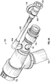
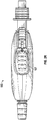
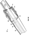
- FIGS. 3H-3J illustrate an example of a multiple-port airway adapter 500.
- Aspects of the airway adapter 500 include, but are not limited to, a ventilator base 531 having an articulable ventilator port 530 projecting from ventilation base 531, an access port 510, and a respiratory port 560.
- a ball 532 and socket 534 connection permits articulation, including rotation, of the ventilator port 530.
- the ventilator port 530 is formed on a first end by the ball 532 socket 534, and a second end by a cylindrical extension 550 protruding from the ball 532.
- a ventilator conduit coupler 552 is coupled to the ventilation base 531 through the ball 532 and socket 534 connection.
- the socket 534 portion of the articulable connection is disposed on the airway adapter 500 between the respiratory port 560 and the access port 5 10.
- the socket 534 further includes a circumferential ridge forming a seat 548.
- the ball portion 532 of the ventilator port 530 is seated within the socket 534 with the cylindrical extension 550 protruding away from the socket 534.
- a lumen extends through the ball portion 532 and the cylindrical extension 550. The lumen tapers as it extends from the ball portion 532 toward the cylindrical extension 550.
- the outer surface of the cylindrical extension 550 includes an undercut, groove, or radially extending circumferential ridge 558.
- the inner surface of the cylindrical extension 550 includes a circumferential ridge 562 extending radially inward.
- the multiple-port airway adaptor 500 includes a flexible tube 546 having a lumen between a first end and an opposing second end.
- a flexible tube 546 having a lumen between a first end and an opposing second end.
- the flexible tube 546 provides a fluid pathway through the ventilator port 530 into the fluid pathway between the respiratory port 560 and the access port 510.
- the first end of the flexible tube 546 is disposed in the seat 548 of the socket 534, thereby improving the mechanical stability of the tube 446 during articulation of the ventilator port 530.
- the second end of the flexible tube 546 extends through the cylindrical extension 550. In some embodiments, a portion of the second end of the flexible tube protrudes beyond the cylindrical extension 550. In some embodiments, a flange 556 extends radially outward from the portion of the second end of the flexible tube 546 that protrudes beyond the cylindrical extension 550. Referring to FIG. 3J , in some aspects, the second end of the flange 556 includes a circumferential groove 564 extending radially outward from an inner surface of the flange 556. In yet other aspects, a circumferential ridge 566 extends radially inward from an inner surface of the circumferential groove 564.
- the first end of the flexible tube 546 is bonded or glued to the seat 548, while the second end permits articulation, including rotation, of the ventilator port 530.
- the second end is not bonded to the seat.
- a seal is provided by an interference fit between the circumferential ridge 562 of the cylindrical extension 550 and the outer surface of the flexible tube 546.
- a seal is provided by the radially extending flange 556 of the flexible tube 546 as it engages the coupler.
- the ventilator port 530 comprises a ventilator conduit coupler 552
- the flange 556 is retained between the end of the cylindrical extension 550 and the ventilator conduit coupler 552.
- the flange 556 is compressed between cylindrical extension 550 and the ventilator conduit coupler 552. However, the frictional force induced against the flange 556 is less than the force required to twist the flexible tube 546. Compression of the flange 556, in some instances, may be in the range of 5% to 33%.
- the flexible tube 546 is comprised of an elastomeric material having a hardness in the range of 60 - 90 Shore A.
- a seal is provided by an interference fit between the circumferential ridge 566 of the flange and the ventilator conduit coupler 552.
- the ventilator conduit coupler 552 is coupled to the ventilator port 530 by advancing the ventilator conduit coupler 552 onto the cylindrical extension 550.
- the ventilator conduit coupler 552 includes an inner surface having an inwardly extending ridge 559 that extends, in some embodiments, circumferentially along the inner surface of the coupler 552 adjacent a circumferentially extending channel.
- One or more window 563 inwardly extending ridge 559 extends through a wall of the coupler 552. The window 563 permits deflection of the ridge 559.
- the ridge 559 engages the circumferential ridge 558, such that one or both of the ridge 558 and the ridge 559 deflect to accommodate an interference fit.
- the ridge 559 bypasses the circumferential ridge 558, permitting the open end of the ventilator conduit coupler 552 to return to an undetected position as the ridge 558 extends into the circumferentially extending channel.
- the ventilator conduit coupler 552 may rotate independent of the cylindrical extension 550.
- the ventilator conduit coupler 552 is coupled with the cylindrical extension 550 in such a way that rotation of one of either the airway adapter 500 or ventilator conduit coupler 552 causes rotation of cylindrical extension 550.
- the second end of the flexible tube 546 is not bonded to the cylindrical extension 550, and rotation of one of either the airway adapter 500, cylindrical extension 550, or ventilator conduit coupler 552 does not cause rotation of the flexible tube 546, thereby preventing twist or collapse of the flexible tube 546.
- a lubricant such as a viscous silicone, may be applied to the flange 556 to further prevent twist or collapse of the flexible tube 546.
- the flexible tube 546 is press-fit into or coupled with an interference fit with the inner surface of the ball 532 and cylindrical extension 500.
- a multiple-port airway adapter 500 is illustrated. Aspects of the airway adapter 500 include, but are not limited to, a ventilator base 531 having an access port 510, an articulable ventilator port 530, and an articulable respiratory port 560.
- Each of the ventilator port 530 and respiratory port 560 include a ball 532 and socket 534 like that described in FIGS. 3H-3J .
- a ball 532 and socket 534 connection permits articulation (e.g., move, pivot, rotate, swivel, tilt, etc.) of the ventilator port 530
- a ball 532' and socket 534' connection permits articulation of the respiratory port 560.
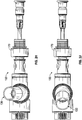
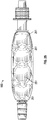
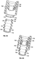
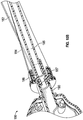
- FIGS. 3K-3M illustrate an example of a multiple-port airway adapter 777.
- Aspects of the airway adapter 777 include, but are not limited to, a ventilator base 731 having an articulable ventilator port 730 projecting from the ventilation base 731, an access port 710, and a respiratory port 760.
- the ventilator port 730 includes a flexible conduit 732 coupled between a ventilator conduit coupler 752 and the ventilation base 731.
- the flexible conduit 732 forms a lumen having a first end coupled to the ventilator base 731 and an opposing second end coupled to the ventilator conduit coupler 752.
- a portion of the lumen wall 733 between the first and second end includes alternating ridges and/or grooves, permitting the flexible conduit 732 to be articulated (e.g., move, pivot, rotate, swivel, tilt, etc.).
- the lumen wall 733 may have a corrugated or popple shape, such as with popple tubing.
- the first and second ends of the flexible conduit 732 form a compression flange 734.
- the compression flange 734 provides a seal between the flexible conduit 732 and the ventilator conduit coupler 752 while permitting the ventilator conduit coupler 752 to rotate with respect to the flexible conduit 732.
- only one end, for example, the second end comprises the compression flange 734.
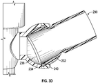
- the flange 734 includes a ledge 738 that extends radially outward from the flexible conduit 732 and a ramped wall 740 that extends transversely from the ledge 738.
- the compression flange 734 extends from an end, or inner surface, of the lumen wall 733 ( FIGS. 3L-3M ).
- the ledge 738 extends radially outward with the ramped wall 740 biased radially inward toward an end of the flexible conduit 732.
- the first end of the ventilator conduit coupler 752 is configured to couple with the second end of the flexible conduit 732, and the second end of the ventilator conduit coupler 752 is configured to couple with a ventilator conduit.
- the ventilator conduit coupler 752 forms a lumen having an outer wall 735 extending between a first end and a second end.
- An inner wall 736 extends from the second end toward the first end.
- the inner wall 736 tapers radially inward from the second end so that a portion of the inner wall 736 is radially spaced from the outer wall 735.
- the inner wall 736 extends a portion of the distance from the second end to the first end.
- the ventilator conduit coupler 752 includes a circumferential channel configured to receive the second end of the flexible conduit 732.
- the circumferential channel is formed between an inner surface of the outer wall 735 and an outer surface of the inner wall 736.
- the circumferential channel is formed by the inner wall 736 and an intermediate wall between the inner wall 736 and the outer wall 735.
- the circumferential channel includes opposing circumferential surfaces, each surface having a ridge.
- a first ridge extends radially inward toward the inner wall 736, and a second ridge on the opposing surface extends radially outward toward the outer wall 735.
- the first and second opposing ridges are axially spaced from each other.
- the circumferential channel comprises a ridge that extends radially outward toward the outer wall 735.
- the compressible flange 734 is advanced into the circumferential channel and a retaining ring 742 is affixed around the flexible conduit 732.
- the retaining ring 742 abuts against the ledge 738 to compress the flange 734 between the retaining ring 742 and the ridge, thereby retaining the compressible flange 734 in the circumferential channel and creating a seal between the flexible conduit 732 and the ventilator conduit coupler 752.
- the retaining ring 742 may comprise one or more pieces, and may be coupled to or bonded to the ventilator conduit coupler 752.
- the second end of the flexible conduit 732 is coupled to the ventilator conduit coupler 752 by inserting the compression flange 734 into the circumferential channel.
- the compression flange 734 is advanced into the circumferential channel until the ramped wall 740 at the second end of the flexible conduit 732 engages the second ridge. Further advancement causes the ramped wall 740 to compress or bias so that the ledge 738 engages the first ridge.
- the distance between the first and the second ridges is less than the distance between the ramped wall 740 and ledge 738, thereby causing the compression flange 734 to remain biased within the circumferential channel.
- the first end of the flexible conduit 732 is coupled to the ventilator port 730 portion of the ventilator base 731 by inserting the ventilator base 731 into the first end of the flexible conduit 732.
- the inner surface of the first end has a diameter that is equal to or slightly less than the outer surface of the ventilator base 731 to provide coupling by interference fit.
- the first end is bonded to the ventilator base 731 using an adhesive or mechanical attachment to prevent axial or rotational movement of the first end with respect to the ventilator base 731.
- the ventilator base 731 can include a circumferential channel that receives the first end of the conduit.
- the airway adapter 777 may include a flexible tube 746 having a lumen between a first end and an opposing second end.
- a flexible tube 746 By incorporating the flexible tube 746 through the flexible conduit 732, extra air space created by the corrugated or popple shape flexible tube 732 wall is bypassed, thereby reducing the amount of dead space in the adapter 777.
- the flexible tube 746 provides a fluid pathway through flexible conduit 732. The first end of the flexible tube 746 is inserted into the ventilator port 730 passage of the ventilator base 731, and the second end is inserted into the passage formed by inner wall 736 of the ventilator conduit coupler 752.
- Each respective end of the flexible tube 746 has an outer surface diameter that is equal to or slightly larger than the inside diameter of the ventilator base 731 and the ventilator conduit coupler 752. In some embodiments, an end of the flexible tube 746 is retained in the seat like that illustrated in FIG. 3I . To permit the ventilator conduit coupler 752 to rotate with respect to the flexible conduit 732, and to prevent the flexible tube 746 from twisting or collapsing, the first end of the flexible tube may be bonded or glued to the ventilator base 731 while the second end is permitted to rotate within the ventilator conduit coupler 752.
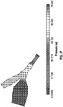
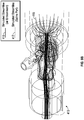
- FIG. 3P illustrates a simulation indicating the pressure drop of flow through the airway adapter 777 of FIGS. 3K-3M .
- the features disclosed herein to reduce excessive air space and to provide minimal resistance to flow through the airway adapter 777 results in a pressure drop of less than 100 Pa.
- aspects of the airway adapter 777 includes a lens 750 to permit visibility into the airway adapter 777.
- a caregiver may read measurement indicators or other information provided on a suction catheter, tubing, or other medical implement inserted through the airway adapter 777.
- the lens 750 is disposed through an outer surface of the ventilator base 731, between the respiratory port 760, ventilator port 730 and access port 110.
- the lens 750 is convex to produce a magnified view into the ventilator base 731.
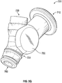
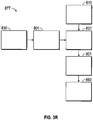
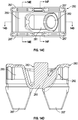
- FIG. 3R illustrates a schematic diagram of an airway adapter 877 including, but not limited to, a ventilator base 831, an access port 810, a ventilator port 830, and a respiratory port 860.
- the ventilator port 830 and respiratory port 860 each include a flexible connector 801 to permit articulation (e.g., move, pivot, rotate, swivel, tilt, etc.) with respect to the ventilator base 831.
- FIGS. 3S-3T illustrate an embodiment of an airway adapter 877 with a ventilator base 831 having an access port 810 comprising a connector body 811.
- the adapter 877 also includes a ventilator port 830, comprising a ventilator conduit coupler 852, and a respiratory port 860, comprising a respiratory conduit coupler 862.
- one or more of the ventilator conduit coupler 852 and the respiratory conduit coupler 862 comprises a flexible connector 801 that connects the one or more couplers 852, 862 to the ventilator base 831.
- both the ventilator conduit coupler 852 and the respiratory conduit coupler 862 comprise a flexible connector 801 that connects the respective coupler with the base 831.
- the flexible connectors 801 permit the ventilator conduit coupler 852, and/or the respiratory conduit coupler 862 to articulate with respect to the ventilator base 831.
- the flexible connector 801 may comprise a resilient material such as an elastomer forming a lumen between a first end and an opposing second end.
- the first end of the flexible connector 801 is coupled to the ventilator base 831 and the second end of the flexible connector 801 is coupled to an adapter or device, for example, the ventilator conduit coupler 852 or the respiratory conduit coupler 862.
- a portion of the first end of the flexible connector 801 is inserted into the ventilator base 831 and a portion of the second end of the flexible connector 801 is inserted into an adapter or device so that an exposed length of flexible connector 801 remains.
- the distance between the ventilator base 831 and the adapter or device is determinative of the degree or range of articulation.
- the range of articulation increases as the exposed length of flexible connector 801 increases, and the range of articulation decreases as the exposed length of the flexible connector 801 decreases.
- the range of articulation is limited by contact between the ventilator base 83 1 and the adapter or device. For example, if airway adapter 877 is disturbed while the respiratory port 860 is coupled to a patient's artificial airway 165 ( FIG. 1A ), the ventilator base 831 will articulate, thereby limiting translation of the disturbance to the patient. Articulation of the airway adapter 877 will be limited when the ventilator base 831 and the respiratory conduit coupler 862 engage each other as best illustrated in FIG. 3T .
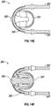
- FIG. 3U illustrates embodiments of an airway adapter 877 like those depicted in FIGS. 3S-3T .
- the airway adapter 877 includes ventilator base 831 having an access port 810 comprising a connector body 811, a ventilator port 830 comprising a ventilator conduit coupler 852, and a respiratory port 860 comprising a respiratory conduit coupler 862.
- a port of the airway adapter 877 includes a flexible connector 801.
- the respiratory conduit coupler 862 is connected to the base 831 by the flexible connector 801.
- the flexible connector 801 comprises a first layer 864 surrounded by a second layer 866.
- the first layer 864 forms a lumen between a first end and an opposing second end.
- the second layer 866 surrounds the outer surface of the first layer 864 between the first and second ends.
- the first layer 864 and the second layer 866 comprise different characteristics.
- the first layer 864 comprises a resilient material that permits elastic deformation
- the second layer 866 comprises a ductile material that permits plastic deformation.
- the first layer 864 may include resilient elastomer such as rubber
- the second layer may include a ductile metal such as copper.
- the second layer 866 may be less resilient or flexible than the first layer 864, the second layer 866 includes features to accommodate articulation of the flexible connector 801.
- the features of the second layer 866 include, but are not limited to, grooves, notches, channels, or interspaced channels passages through the wall of the second layer 866.
- the flexible connector 801 permits the airway adapter 877 to remain in the articulated position, while in other embodiments the combined materials permit temporary articulation before causing the flexible connector 801 to return to a neutral state.
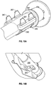
- FIGS. 3V-3X illustrate an embodiment of a flexible connector 801 coupled to the ventilator port 830 of an airway adapter 877.
- the flexible connector 801 permits the ventilator port 830 to be articulated and remain in the articulated position. Although illustrated as coupled to the ventilator port 830, the flexible connector 801 may be coupled to any port on the airway adapter 877.
- the flexible connector 801 includes a lumen between a first end and an opposing second end.
- the flexible connector 801 includes a first, resilient material, and a second, ductile, material.
- the second material is distributed with the first material between the first and second ends.
- the second material may be disposed along and inner or outer surface of the lumen, or may be embedded in a wall of the lumen.
- the second material is embedded into the wall as the lumen is extruded.
- the wall of the lumen includes a passage between the first and second ends wherein the second material is a wire disposed within the passage. Referring to FIGS. 3V-3W , a portion of the inner surface of the wall is raised to accommodate the passage and wire the first and second end. Referring to FIG. 3X , a portion of the outer surface of the wall is raised to accommodate the passage and wire the first and second end.
- the respiratory port 160 is configured for fluid connection to an artificial airway 165 ( FIG. 1A ) otherwise establishing a direct connection to the patient's respiratory tract.
- the respiratory port 160 can be fluidly connected to an endotracheal tube or a tracheostomy tube.
- the respiratory port 160 includes an annular swivel connector 162, allowing the multiple-port airway adapter 100 to rotate, with respect to the swivel connector 162, about the fluid pathway axis.
- the swivel connector 162 comprises a circumferential flange 164 that extends radially from the outer surface. When the swivel connector 162 is coupled to the multiple-port airway adapter 100, the flange engages the inner surface of the fluid pathway.
- the swivel connector 162 may be coupled to a patient's artificial airway 165.
- the swivel connector 162 may be rotated in either direction to further assist with coupling the respiratory port 160 while minimizing or reducing disruption, discomfort, or trauma to the patient.
- the tubing of a ventilation device (not shown) may be coupled with the ventilator port 130. Because the ventilator port 130 is articulable, the ventilation device may be coupled or relocated without applying additional force on the multiple-port airway adapter 100 or artificial airway of the patient.
- the multiple-port airway adapter 100 may further include an intermediate ring 168 disposed around the circumference of swivel connector 1 62.
- the intermediate ring 168 may abut against flange 164, preventing or limiting translational movement of the swivel connector 162 along the fluid pathway axis (e.g., axial center 101), yet allowing the swivel connector 162 to rotate about the fluid pathway axis.
- respiratory conduit 161 may comprise transversely extending protrusions 166 on an exterior surface.
- the protrusions 166 provide additional rotational leverage when coupling or decoupling the respiratory port 160 with an artificial airway (e.g., an intubated patient's ETT or tracheostomy tube).
- the protrusions 166 may extend outward and parallel to each other, and in some embodiments, the protrusions 166 may extend radially outward.
- the swivel connector 162 can provide one or more depressions (not shown) that permit additional gripping capacity by a user of the swivel connector 162.
- a series of dimples may be disposed around the circumference of the swivel connector 162 outer surface.
- the portion of the swivel connector 162 not inserted into the fluid pathway 146 is at least one-eighth inch in length.
- valve 120 is configured such that it provides a substantial fluid barrier between the elongate cavity 115 of connector body 111 and the ventilation chamber 135 of ventilation base 131.
- Valve 120 may be positioned for biasing or spring action such that a generally concave side of the valve 120 is positioned facing the elongate cavity 115 side (e.g., catheter insertion or vacuum suction side), and a generally convex side of the valve 120 is positioned facing the ventilation chamber 135 side.
- Ventilation base 131 may be configured as a manifold structure including a connection to the respiratory conduit 161 and a ventilation source opening 137.
- the ventilation source opening 137 is fluidly coupled to the tubular portion 133 of the ventilation base 131 and the respiratory conduit 161.
- valve 120 comprises a primary seal and secondary seal that are designed to provide a substantial fluid barrier at low pressure differentials (e.g., below 68 cm H 2 O).
- valve 120 is disposed adjacent to an end of the tubular portion 133 with respect to the longitudinal alignment of the tubular portion 133 in the ventilation base 131.
- the valve 120 is disposed such that the valve is not located in a direct fluid pathway 139 from the ventilation source opening 137 and the respiratory conduit 161, for example, when a ventilator is operatively coupled to the ventilator port 160 of the airway adapter 100.
- the valve 120 may be positioned a distance 141 (e.g., between 6 mm and 12 mm) from the ventilation source opening 137.
- the positioning of the valve 120 with respect to the direct fluid pathway 139 is one of several factors that may be considered when configuring the valve 120 to operate at a low initial cracking pressure for the secondary valve.
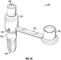
- FIG. 4 illustrates an example of an airway adapter coupler 170.
- airway adapter coupler 170 can be coupled to the first end 113 of connector body 111.
- airway adapter coupler 170 comprises a wiper seal 172 having an inward flange and an access aperture 194.
- the inward flange of the wiper seal 172 may comprise a transverse wall with respect to the axial center 101.
- the inward flange can be angled with respect to the axial center 101.
- the inward flange may be angled toward the second end 119 of the connector body 111 thereby forming a frustoconical wiper seal or frictional member when coupled to the access port 110 of the airway adapter 100.
- the wiper seal 172 and associated aperture size can be configured to receive a suction catheter or other medical implement for accessing the elongate cavity 115 of the connector body 111.
- airway adapter coupler 170 is connected to a suction catheter sheath and can removably coupled to the first end 113 of connector body 111 of the airway adapter 100.
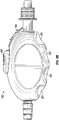
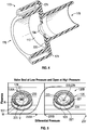
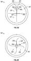
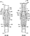
- FIG. 5 illustrates an example of a multiple-purpose valve.
- valve 120 comprises a rim 123 along an outer circumferential section.
- the rim of a multiple-purpose valve can be various shapes (e.g., oval, square, hexagonal, pentagonal, etc.).
- Valve 120 also comprises a diaphragm section 125 that is resiliently flexible in accordance with certain embodiments.
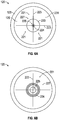
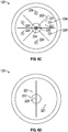
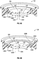
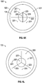
- the diaphragm section 125 is integrally connected to the rim 123 and comprises a plurality of valve segments 221 defined by one or more slits 223 (see additional aspects related to the valve segments 221 and one or more slits 223 is illustrated in FIG. 6A-6F and 6K-6N ).
- a valve segment 221 may include a first region 225 and a second region 227.
- a primary seal 231 of the valve 120 is formed by the plurality of valve segments 221 disposed on the diaphragm section 125.
- Valve 120 also includes a secondary seal 233.
- the secondary seal 233 is formed by an arrangement of one or more first regions 225 of the valve segments 221.
- the primary seal 231 refers to a larger seal of the valve 120 for allowing a suction catheter (or other medical implement) to pass therethrough. After the suction catheter has been removed, the primary seal 231 returns to its original unbiased configuration.
- the secondary seal 233 of the valve 120 refers to a small seal (e.g., a smaller seal than the primary seal 231) for allowing and regulating an amount of air (generally a small amount) from the ventilation chamber 135 to enter into the elongate cavity 115 so as to clean the suction catheter after it has been retrieved from the artificial airway 165 or the patient's airway. Accordingly, the secondary seal 233 of valve 120 acts as an air-entrainment valve in accordance with certain aspects.
- valve 120 is configured to withstand a certain amount of differential pressure and maintain a seal above atmospheric pressure.
- the secondary seal 233 has a first cracking pressure 235
- the primary seal 231 has a second cracking (or breaching) pressure different from the first cracking pressure 235.
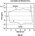
- Valve 120 may be configured such that the first cracking pressure may be defined within a range between the lower threshold 235a and the upper threshold 235b as illustrated in the chart of FIG. 5 (for illustration purposes; not drawn to scale).
- a lower threshold 235a may be established at approximately 68 cm H 2 O
- an upper threshold 235b may be established at approximately 188 cm H 2 O.
- valve 120 may be configured such that air-entrainment may be accomplished between the range of the lower threshold 235a and the upper threshold 235b, proximal to the lower threshold 235a in some implementations.
- a suction catheter positioned in the elongate cavity 115 of the connector body 111 providing 120 cm H 2 O of vacuum pressure with the first cracking pressure 235 range may cause the secondary seal 233 to be breached in a controlled manner such that air-entrainment into the elongated cavity 115 may be performed while minimally affecting (if at all) the ventilation function occurring between the ventilator port 130 and the respiratory port 160.
- the second cracking/breaching pressure 237 of the primary seal 231 may be significantly larger than the first cracking pressure 235 range such that suctioning or vacuum pressure differentials will not have a meaningful effect on the primary seal 231.
- the cracking or breaching associated with the entirety of the primary seal 231 of valve 120 may be caused by insertion of a medical implement therethrough and are associated with the cleaning and scraping functions of the valve 120, in accordance with certain embodiments.
- valve 120a Under normal operation of a mechanical ventilation breathing circuit (e.g., ventilation source applied at the ventilator port 130 directed to artificial airway 165 via respiratory port 160 by airway adapter 100), the differential pressure at valve 120 of airway adapter 100 remains below the first cracking pressure 235. At this low range of differential pressure, an effect of such differential pressure on valve 120 in operation will appear as valve 120a.
- a mechanical ventilation breathing circuit e.g., ventilation source applied at the ventilator port 130 directed to artificial airway 165 via respiratory port 160 by airway adapter 100
- valve 120 When a suction force is applied at the access port 110, when the valve 120 is not physically breached by a medical implement (e.g., suction from a suction catheter with the tip end of the suction catheter in the elongate cavity 115 of the connector body 111), the differential pressure at the valve 120 will be at or above the first cracking pressure 235, but below the second cracking pressure 237, in accordance with certain embodiments. At this differential pressure range, the effect of such differential pressure during operation of artificial airway 100 will cause valve 120 to appear as valve 120b having the secondary seal 233 breached.
- a medical implement e.g., suction from a suction catheter with the tip end of the suction catheter in the elongate cavity 115 of the connector body 111
- valve 120 is configured such that an expected suction force or range of suction forces does not cause a breach of the primary seal 231, as such a breach during air-entrainment would have an undesirably adverse effect on the patient's respiratory function by removing too much air from the ventilation source.
- the diaphragm section 125 of valve 120 may include a ramped area 127 and a segment area 129.
- the ramped area 127 e.g., frustoconical, rounded, raised, etc.
- the ramped area 127 may function as a biasing mechanism to aid in returning the valve 120 to the original sealed configuration after a suction catheter or other medical implement has been removed.
- the one or more slits 223 arranged on the diaphragm section 125 to form the plurality of valve segments 221 may be entirely disposed on the segment area 129.
- the segment area 129 may be substantially flat or plateaued in relation to the ramped area 127; however it is understood that variations in thickness of the diaphragm section 125 within the segment area 129 exist from the first regions 225 and the second regions 227 of the valve segments 221 that form aspects of the primary seal 231 and the secondary seal 233.
- the rim 123 of valve 120 may be circumferential and have a width (W) that is less than a radius (R) of the rim 123.
- the width (W) of the rim 123 can define a volume (V) of the valve 120 than can be viewed as drum-shaped.
- the width (W) of the rim 123 may be of sufficient width such that when the valve 120 is retained in a valve retention structure of the airway adapter 100, a sufficiently air tight seal can be achieve.
- one of many distinguishing features of valve 120 can be understood with respect to the drum-shaped volume described.
- diaphragm section 120 may include ramped area 127 in certain embodiments, the ramped area 127 may not extend to a duck-bill type configuration at least with respect to some embodiments of the valve.
- the ramped area 127 and segment area 129 of the diaphragm section 125 may be disposed within the drum volume (V) by the width (W) of the rim 123 when the valve is in an unbiased configuration (e.g., when the no differential pressure is applied to the valve 120 and the rim 123 is not compressed in a valve retention structure).
- certain embodiments of valve 120 can be seen as substantially planar, and thereby the plurality of valve segments can be extendable into both sides or zones to which the valve 120 serves as a breachable barrier or seal.
- the rim 123 and diaphragm section 125 may comprise one of polysilicone, polyurethane, or polythermoplastic elastomer, in certain embodiments.
- valve segments 221 of valve 120 may include one or more first regions 225 and one or more second regions 227.
- the primary seal 231 of valve 120 may be formed by the plurality of valve segments 221, and the secondary seal of valve 120 may be formed by an arrangement of the one or more first regions 225 of the one or more valve segments 221.
- the one or more first regions 225 may comprise a gradient thickness on at least a portion of the one or more first regions 225, For example, with additional reference to the cross-section views in the examples of FIG.
- a first thickness 125A of a first region 225 may be defined proximal to or at an intersection of the one or more slits 223, and a second thickness 125B may be defined proximal to or at a transition or border of the secondary seal 233 (e.g., FIGS. 6A , 6E, and 6F ).
- the second thickness 125B is greater than the first thickness 125A in accordance with certain aspects.
- the variation in thickness permits the valve 120 to comprise a varying reaction to air pressure (e.g, cracking pressure) and interaction with a medical implement being passed through valve 120 (e.g, a suction catheter).
- the valve segments 221 include a first surface proximal to the leading edge 122 of the valve 120, and a second surface distal from the leading edge 122 of the valve 120.
- the first surface comprises a first radius R2, and the second surface comprises second radius R4.
- the first radius R2 and the second radius R4 are not equal.
- the first radius R2 may be in the range of .1332 to .1628 inches
- the second radius R4 may be in the range of .3555 to .4345 inches.
- the first radius R2 is .148 inches and the second radius R4 is .395 inches.
- one or more of the valve segments 221 may further include one or more raised areas 224 on one or more of the first regions 225 and/or second regions 227 (e.g., FIGS. 6A-6C ). Accordingly, the one or more raised areas 224 may be formed as a bead or bump at an intersection of the one or more slits 223 (e.g., FIGS. 6A and 6G ) such that the first thickness 125A is less than the raised thickness 125A of the one or more raised areas 224.
- the one or more raised areas 224 may be formed as a ring or annular bump structure disposed within the one or more second regions 227 of the valve segments 221 (e.g., FIG. 6B ) proximal to the one or more first regions 225. In other embodiments, the one or more raised areas 224 may be disposed both within the one or more first regions 225 and the one or more second regions 227 of the valve segments 221 (e.g., FIG.
- the one or more raised areas 224 may be disposed distal from the one or more first sections 225 so as to be positioned near a portion of the diaphragm section 125 having a greater frictional force or resiliency proximal to the ends of the one or more slits 223, for example, when a suction catheter (or other medical implement) is inserted through the valve 120.
- the protrusion portions of the one or more raised areas 224 may be disposed on a top surface of the diaphragm section 125 of the valve 120 facing an access port for receiving the suction catheter (e.g., when assembled in airway adapter 100).
- valve 120 and the plurality of valve segments 221 thereof may open and conform in a direction of catheter movement. For example, when the suction catheter begins to retract from the artificial airway, frictional force by contact of the one or more raised areas 224 with the suction catheter will invert the valve segments 221 thereby pulling valve 120 towards the direction of retraction promptly and consistently, in accordance with certain aspects.
- one or more raised areas 224 of the one or more first regions 225 disposed at or near a tip of each valve segment 22.1 and/or other portions of one or more valve segments 221 can be configured to add an extra radial contact or force (e.g., providing better traction) when the suction catheter is to be retracted from the artificial airway.
- one or more raised areas 224 may be positioned within or proximal to the one or more first regions 225 (e.g., at or proximal to an intersection of at least some of the one or more slits 223).
- the one or more raised areas 224 may similarly aid in keeping direct contact with the suction catheter (e.g., preventing the thinner portions 125A and 125B of the first regions 225 from bowing convexly or away from the outer surface of the suction catheter).
- the additional thickness by one or more raised areas 224 positioned proximal to or at the intersection of the one or more slits 223 may also aid valve 120 to reseal or close faster and/or more securely when the suction catheter is fully retracted.
- the one or more raised areas 224 may be formed from the same material as the other portions of the diaphragm section 125. However, in other implementations, the one or more raised areas 224 may be formed to include other materials or compounds to increase the rigidity or frictional characteristics of the one or more raised areas 224.
- the one or more second regions 227 may have a third thickness 125C.
- the third thickness 125C of the one or more second regions 227 is greater than the second thickness 125B of the one or more first regions 225, in accordance with certain aspects, and can provide sufficient rigidity for operation of valve 120 in airway adapter 100.
- the thickness and rigidity of the one or more second regions 227 can aid in securing and scraping a suction catheter during retrieval from the artificial airway 165.
- valve 120 may have a third region 229 encircling both the one or more first regions 225 and the one or more second regions 227.
- the third region 229 may comprise an arcuate cross-sectional biasing feature disposed proximal to the outer rim section.
- the arcuate cross-sectional biasing feature includes an apex thickness greater than the first thickness of the one or more first regions.
- the third region 229 may have a fourth thickness 125D (e.g., an apex thickness) that is greater than the first thickness 125A, and in some implementations, thicker than the second thickness 125B, and/or the third thickness 125C.
- the third region 229 may provide a biasing function of valve 120 with the inner angled wall portion 117 of the airway adapter 100 ( FIG. 3B ) such that the valve 120 may return to an unbiased position after removal of the suction catheter as well providing additional support for the scraping function of the plurality of valve segments 221.
- the diaphragm section 125, and particularly the third region 229 (e.g. radial bump portion) of the diaphragm section 125 may not have any contact with the valve housing interior (e.g., inner angled wall portion 117 of the airway adapter 100 ( FIG. 3B )).
- the third region 229 e.g. radial bump portion
- the third region 229 may move into and contact the inner angled wall portion 117.
- this contact force can provide support for scraping the suction catheter as the suction catheter retracts and a "push off" resilient force when the suction catheter is fully retracted and the valve 120 begins to reseal.
- the arcuate cross-sectional biasing feature of the third region 229 permits inversion of the valve segments 221, thereby pulling valve 120 towards the direction of retraction.
- the arcuate cross-sectional biasing feature of the third region 229 may function to support prompt (e.g., no or minimal delay) and proper (e.g., no leaking) self-resealing of valve 120.
- the third region 229 may also provide friction control and biasing functions of valve 120 such that the valve 120 may be more receptive to movements of the suction catheter (e.g., lateral or transverse movements with respect to the axial center 101 of airway adapter 100 ( FIG. 3B )) while inserted therethrough, and may return to an unbiased position after the suction catheter has been removed, for example.
- movements of the suction catheter e.g., lateral or transverse movements with respect to the axial center 101 of airway adapter 100 ( FIG. 3B )
- the third region 229 of valve 120 may comprise an arcuate cross-sectional biasing feature disposed proximal to the outer rim section that includes a bend portion 229A and two opposing wall portions 229B, 229C.
- the third region 229 may comprise a circumferential accordion bellow with a generally "V"-shaped cross-section in accordance with certain embodiments thereby providing improved shape and flexibility.
- the arcuate cross-sectional biasing feature may include an apex thickness greater than the first thickness of the one or more first regions.
- the third region 229 may have a fourth thickness 125D (e.g., an apex thickness at bend portion 229A) that is greater than the first thickness 125A.
- the fourth thickness 125D may be thicker than the first region, but thinner than the third thickness 125C.
- the third region 229 can provide a consistent radial and friction force with respect to a suction catheter (or other medical implement) inserted through the valve 120.
- the third region 229 in the example embodiment of FIG. 6H may provide a biasing function of valve 120 whereby the two opposing wall portions 229B, 229C may approach one another at sections distal of the bend portion 229A (e.g., closing or narrowing of the "V"-shaped cross-section) as a suction catheter (or other medical implement) is being retracted from the artificial airway and return to an unbiased position (e.g., revert back to the "V-shaped cross-section aiding the valve segments 221 to fully close) when a tip of the suction catheter has been removed through the valve 120 and into the access zone or cleaning chamber of the airway adapter 100.
- an unbiased position e.g., revert back to the "V-shaped cross-section aiding the valve segments 221 to fully close
- the third region 229 may retain its shape and flexibility during suction catheter insertion/retraction operations and thereby aid in stabilizing valve 120 and returning the valve 120 to an unbiased position (e.g., close valve segments 221 and reseal the valve 120). Additionally, the third region 229 may promote inversion of the valve segments 221, for example, when the suction catheter (having either a wet or dry outer surface) starts to retract and pull back the valve 120 in a direction of the retracting motion during operation of the airway adapter 100.
- the arcuate cross-sectional biasing feature may include an apex thickness less than the first thickness of the one or more first regions.
- the third region 229 may have a fourth thickness 125D (e.g., an apex thickness at bend portion 229A) that is less than the first thickness 125A.
- the fourth thickness 125D may also be thinner than a third thickness 125C, located radially between the first thickness 125A and the fourth thickness 125D.
- the third region 229 can provide a consistent radial and friction force with respect to a suction catheter (or other medical implement) inserted through the valve 120.
- the intersection 226 of the slits is offset from the center of the valve 120 by a radial distance 228.
- the third region 229 may comprise an arcuate cross-sectional biasing feature disposed proximal to the outer rim section that includes bend portions 229A and 229AA, and three opposing wall portions 229B, 229C, and 229D.
- the third region 229 may comprise a circumferential accordion bellow with a generally "S"-shaped cross-section in accordance with certain embodiments thereby providing improved shape and flexibility.
- bend portion 229AA is coupled to wall portion 229D
- bend portion 229A is coupled to wall portion 229B, such that wall portion 229C extends between bend portions 229A and 229AA.
- bend portion 229AA is distal from the leading edge 122 of the valve 120 while bend portion 229A is proximal to the leading edge 122 of the valve 120.
- the third region 229 may provide a biasing function of valve 120 whereby the three opposing wall portions 229B, 229C, and 229D may approach one another at sections distal of the bend portions 229A and 229AA (e.g., closing or narrowing of the "S"-shaped cross-section) as a suction catheter (or other medical implement) is being retracted from the artificial airway and return to an unbiased position (e.g., revert back to the "S"-shaped cross-section aiding the valve segments 221 to fully close) when a tip of the suction catheter has been removed through the valve 120 and into the access zone or cleaning chamber of the airway adapter 100.
- an unbiased position e.g., revert back to the "S"-shaped cross-section aiding the valve segments 221 to fully close
- the third region 229, particularly the bend portion 229A may also provide radial and friction force control of valve 120 such that the valve 120 may be more flexible and receptive to the movement of a suction catheter or other medical instruments (e.g., valve being pulled towards the direction of catheter movement) during insertion and retraction and may help return to an unbiased position after the suction catheter has been removed from extending through the valve 120.
- a suction catheter or other medical instruments e.g., valve being pulled towards the direction of catheter movement
- the arcuate cross-sectional biasing feature may include an apex thickness less than the first thickness of the one or more first regions.
- the third region 229 may have a fourth thickness 125D (e.g., an apex thickness at bend portion 229A) that is less than the first thickness 125A.
- the fourth thickness 125D may also be thinner than a third thickness 125C, located radially between the first thickness 125A and the fourth thickness 125D.
- the bend portion 229A and wall portion 229C have a consistent thickness.
- the fourth thickness 125D may be in the range of .0135 to .0165 inches.
- the fourth thickness 125D is .015 inches.
- the third region 229 can provide a consistent radial and friction force with respect to a suction catheter (or other medical implement) inserted through the valve 120.
- the intersection of the slits 223 is offset from the center of the valve 120 by a distance 228.
- the third region 229 may comprise an arcuate cross-sectional biasing feature disposed proximal to the outer rim section that includes bend portions 229A and 229AA, and three opposing wall portions 229B, 229C, and 229D.
- a flat surface of the inner resiliently flexible diaphragm section extends orthogonally from an inner surface of the outer rim 123 to bend portion 229AA.
- a surface of bend portion 229A proximal to the leading edge 122 may form a plateau and have a radius R6 between bend portion 229A and wall portion 229C, and a radius R8 between bend portion 229A and the valve segments 221.
- the radius R6 may be in the range of .018 to .022 inches, and the radius R8 may be in the range of .063 to .077 inches. In an embodiment, the radius R6 is .020 inches and the radius R8 is .070 inches.
- valve 120 Other aspects of valve 120 are illustrated in the examples of FIGS. 6A-6F and 6K-6N.
- the one or more slits 223 may have different lengths (e.g., valves designed for a 6 Fr. catheter versus a 16 Fr. catheter), the number and shape of slits 223 and corresponding valve segments 221 may vary, and/or the area of the secondary seal 233 may be different in various implementations.
- the slits 223 and/or 223X may form a cross-shaped pattern through the diaphragm section 125 (e.g., FIGS. 6A-6C and 6K).
- the slits 223 and/or 223X may form a symmetric pattern through the diaphragm section 125. In other embodiments, the slits 223 and/or 223X may form an asymmetric pattern through the diaphragm section 125 (e.g., FIGS. 6E, 6F , and 6L ). For example, the slits 223 illustrated in FIG. 6L form a star pattern. Additionally, in some implementations, the one or more second regions 227 may comprise a greater surface area of the diaphragm section 125 than the one or more first regions 225.
- the valve 120 comprises one or more minor slit 223X that may intersect or extend from and end of the slit 223.
- the length 223L of a minor slit 223X may be in the range of .0123 to .0187 inches.
- the length 223L of a minor slit 223X is .017 inches.
- an angle of a minor slit 223X relative to the slit 223 may be in the range of 10 to 30 degrees.
- two minor slits 223X extend from an end of the slit 223 to form a "Y"-shaped pattern with the slit 223.
- an angle 223A of the minor slits 223X relative to each other is in the range of 15 to 60 degrees. In an embodiment, the angle 223A between two minor slits 223X is 30 degrees.
- a resealable opening of the secondary seal 233 may be defined by the intersection of the one or more slits 223.
- the resealable opening of the secondary seal 233 is aligned with a resealable opening of the primary seal 231.
- the resealable opening of the primary seal 231 extends farther than that of the secondary seal 233.
- the resealable opening of the secondary seal 233 and the resealable opening of the primary seal 231 may be aligned with an approximate center of the diaphragm section 125.
- the approximate center of the diaphragm section 125 of valve 120 when retained in airway adapter 100 may be aligned with the axial center 101 of the elongate cavity 115 of the connector body 111 ( FIG. 3B ).
- the first region 225 of the valve segment 221 can be configured such that an end proximal to the axial center 105 has a thickness of the first thickness and a portion distal from the axial centerline that has a thickness of the second thickness.
- a resealable opening of the secondary seal 233 can be located at a different position on the diaphragm section 125 than proximal to the center of a resealable opening of the primary seal 231 (e.g., FIG. 6E ).
- the resealable opening of the secondary seal 233 may be located within the diaphragm section 125 proximal to the rim 123, whereas resealable opening of the primary seal 231 may be located at the approximate center of the diaphragm section 125.
- the secondary seal 233 may be formed from a different set of one or more slits 223 than the primary seal 231 within the diaphragm section 125 (e.g., a first set of one or more slits associated with the primary seal and a second set of one or more slits associated with the secondary seal).
- the slits and first portions of the secondary seal can be located in one of the quadrants defined by the larger slits that make out the primary seal.
- the one or more first regions 225 may be disposed on the diaphragm section 125 at an intersection of at least some of the one or more slits 223 and have a thinnest thickness at an intersection of the one or more slits 223 (e.g., without including raised areas 224, FIGS. 6D , 6E, and 6F ).
- FIG. 7 illustrates a flow diagram of an example method related to use and cleaning aspects of an airway adapter. It is to be understood that the operations in method 400 may be used in conjunction with other methods and aspects of the present disclosure. Although aspects of method 400 are described with relation to the examples provided in FIGS. 8A-8C and 9A-9B , as well as reference to certain examples provided in FIGS. 1 to 6F , process 400 is not limited to such.
- a suction catheter may be extended through an access zone of an airway adapter into a ventilation zone of the airway adapter such that a primary seal formed by a plurality of valve segments is breached.
- suction catheter 185 may be extended through access zone 175 into ventilation zone 177 such that a primary seal 231 of valve 120 formed by a plurality of valve segments 221 is breached.
- at least some of the valve segments 221 extend toward the ventilation zone 177. Friction forces on the suction catheter 185 with respect to the distance extended into a patient airway in accordance with certain embodiments are illustrated in the chart of FIG. 8C .
- the suction catheter may be retracted in a direction from the ventilation zone to the access zone.
- suction catheter 185 (or tubing coupled thereto) may be retracted or retrieved from the ventilation zone 177 to the access zone 175.
- at least some of the valve segments 221 of valve 120 extend toward the ventilation zone 177.
- one or more raised areas 224 may aid in keeping direct contact with the suction catheter 185 and causing the valve segments 221 to invert and extend toward the access zone 175.
- valve 120 embodiments can be to scrape a surface of the suction catheter 185 as it is retracted or withdrawn from the patient's airway so as to clean, at least partially, the catheter surface, for example.
- these substances may accumulate and potentially occlude the airway.
- valve 120 configuring valve 120 such that the valve segments 221 (particularly the one or more second regions 227) are sufficiently rigid and flexible such that the valve segments 221 can effectively support and/or scrape the suction catheter 185 as well as invert toward the access zone 175 during retraction so the mucus, secretions, and other fluids accumulate where these substances can be removed by the suction catheter provides an advantage of an airway adapter comprising valve 120.
- the plurality of valve segments 221 of the valve 120 may be configured to form a primary seal 231 and a secondary seal 233.
- Valve 120 is configured such that it will revert back to an unbiased configuration when the suction catheter 1 85 is fully retracted into the access zone 175 and no longer engaged with the valve 120.
- third region 229 of valve 120 may provide a biasing function of valve 120 with the inner angled wall portion 117 of the airway adapter 100 such that the valve 120 may return to an unbiased position after removal of the suction catheter 185.
- the primary seal 231 and secondary seal 233 will again form a fluid barrier between the ventilation zone 177 and the access zone 175.
- one or more protrusions 179 may be disposed on an inner wall of the connector body 111 in the access zone 175.
- the protrusions 179 may extend from the inner wall toward the axial center of the elongate cavity 115.
- Each protrusion 179 comprises an inclination surface 301, a return surface 302 extending transversely to the inclination surface 301, and an apex area 303 that transitions between the ramp surface and the engagement surface.
- the apex area 303 is parallel to the axial center of the elongate cavity 115.
- the protrusions 179 direct a suction catheter 185 toward the axial center of the elongate cavity 115.
- the protrusions 179 extend an equal distance toward the axial center of the elongate cavity 115 such that the suction catheter 185 aligned with the center of the valve 120.
- the protrusions 179 extend varying distances into the elongate cavity 115 such that the suction catheter 185 is aligned a radial distance from the center of the valve 120.
- the protrusions 179 extend varying distances into the elongate cavity 115 such that the suction catheter 185 is aligned with the intersection 226 of the slits, a distance 228 from the center of the valve 120.
- tip end 189 of the suction catheter 185 may engage one or more inclination surface 301 such that suction catheter 185 is generally directed toward a point between the apex areas 303 of the protrusions 179.
- the suction catheter 185 will remain between the apex areas 303. Maintaining alignment of the suction catheter 185 within the elongate cavity 115 provides control over the point of engagement between the tip end 189 of the suction catheter 185 and the valve 120.
- the protrusions 179 maintain the suction catheter 185 in coaxial alignment with the elongate cavity 115 during insertion and retraction through the access zone 175.
- a tip end of a suction catheter may be aligned within an access zone 175 of an airway adapter.
- suction catheter 185 may be aligned or positioned such that tip end 189 of the suction catheter 185 is positioned between valve 120 and an airway adapter coupler 170.
- each of the primary and secondary seals 231, 233 provides a breachable seal between access zone 175 and ventilation zone 177 of the airway adapter.
- the airway adapter coupler 107 includes a wiper seal 172 having a wall portion and an access aperture.
- the wiper seal 172 may be configured to provide a slidably frictional fitting with the suction catheter 185.
- a solution may be injected into a flush port of the airway adapter that is in fluid communication with the access zone 175.
- the tip end 189 of the suction catheter 185 may be positioned in the access zone 175.
- Saline or a cleaning solution may then be injected via flush port 116 into the access zone 175 fluidly coupled to the flush port 116, for example, thereby providing a cleaning chamber for the suction catheter 185.
- saline or a cleaning solution may be injected into the flush port 116 via a wash port valve assembly 600 (e.g, FIGS. 2A-2K and 9C-9E).
- a suction force to the suction catheter may be applied.
- suction force 195 may be applied to the suction catheter 185 such that the secondary seal 233 of the valve 120 is breached, causing airflow from the ventilation zone 177 into the access zone 175.
- an airway adapter comprising valve 120 may include a volume (e.g., access zone 175 or elongate body 115) for cleaning a catheter tip or other medical implement (e.g., Mini-BAL device or a bronchoscope) following a suctioning or other airway procedure.
- Valve 120 is configured to allow a small amount of air (relative to the amount and flow generated by a ventilation source of a particular patient's artificial airway circuit) through the seal so as to entrain air into the fluid flow of saline or cleaning solution so as to improve the cleaning procedure effectiveness.
- FIG. 9B illustrates an example of an air-entrainment simulation of the multiple-port airway adapter used with the suction catheter provided in the example of FIG. 9A .
- Air-entrainment simulation 413 includes air entrainment traces 415 and solution traces 417. As can be seen in air-entrainment simulation 413, agitation of the solution with the air significantly enhances the effectiveness of the cleaning procedure, for example, in the small volume cavity or chamber in which the suction catheter or medical implement is cleaned.
- a medical implement other than a suction catheter can be used in method 400.
- the connector body may include an additional suction port in fluid communication with the elongate cavity such that both solution injection and suction can be performed without use of the suction catheter.
- the airway adapter coupler may include a suction port and a medical implement feed port enabling suctioning of the saline or cleaning solution during the cleaning process.
- valve 120 is resiliently flexible so as to have a biasing (or springing) characteristic, which returns the valve 120 to a normally fluidly closed configuration.
- biasing or springing
- a device without the benefit of the present disclosure may have a valve that scrape large volumes of mucus and other fluids from the catheter, but block or entrap these fluids whereby the mucus and fluids are displaced to a position from which the displaced mucus and fluids cannot be easily suctioned away as a suction catheter is withdrawn.
- the mucus and outer fluids from a device without the benefit of the present disclosure may then accumulate to the point of occluding or contaminating an airway of a patient causing harm to the patient.
- Method 400 and an airway adapter comprising valve 120 minimize the aforementioned patient risks, and represent an improvement in the art.
- Valve 120 may be formed from a single elastomeric web of material with specific morphological and elastic properties (e.g., durometer, elongation, tear strength, etc.), in accordance with examples and embodiments disclosed herein. Valve 120 may be seated and sealed to the interior structure of airway adapter 100 and thereby retained against accidental dislocation.
- specific morphological and elastic properties e.g., durometer, elongation, tear strength, etc.
- valve 120 At pressures below a first cracking pressure, valve 120 may be closed to fluid flow; at pressures ranging from the first cracking pressure to a second cracking pressure, a small flow of air from the patient's airway (relative to the total flow of ventilator air) may be entrained into a cleaning space or access zone in the airway adaptor; and at pressures above the second cracking pressure, valve 120 will open causing air to flow through the valve.
- Specific attributes of valve 120 may vary depending upon an intended patient population for which a particular valve is designed. For example, a particular valve designed for a 6 Fr. catheter, used for neonatal patients may have first and second cracking pressures lower than a particular valve designed for 16 Fr. catheters used on adults.
- Valve 120 may be designed such that the one or more slits in the diaphragm section of the valve 120 can stretch to allow passage of the closed suction catheter or other airway instruments (e.g. a Mini-BAL device or a bronchoscope) without tearing the valve 120.
- airway instruments e.g. a Mini-BAL device or a bronchoscope
- valve 120 may substantially conform to an outer diameter of the suction catheter and extend and/or elongate in a direction of catheter motion, forming a conical volume on a ventilation zone or ventilator machine side of the valve 120.
- a shape of valve 120 may invert, forming a conical volume on an access zone or cleaning chamber side of the valve 120.
- the mucosal or other fluids may then accumulate in the vicinity of the conical volume formed by the diaphragm section of the valve 120 and the access zone or cleaning chamber.
- the suction pressures at the eyes and terminus of the suction catheter will evacuate much of the accumulated mucosal or other fluids, thus cleaning the area of excessive and potentially occluding fluids.
- FIGS. 9C-9E illustrate a wash port valve assembly 600.
- the wash port valve assembly 600 comprises a body 610 and a port 662.
- An inlet 624 is configured to receive saline or a cleaning solution for injection into the flush port 116, while an outlet 618 is configured to fluidly couple with the tubular connector 602 of the wash port coupling assembly 216.
- a cap 700 is coupled to the wash port valve assembly 600 through a collar 702 and hinge 704.
- the body 610 comprises a first end 612, a second end 614, an inlet 624, and an outlet 618.
- the body 610 houses a check valve member 680 comprising a compressible member 630.
- the port 662 at least partially defines the inlet 624.
- the body 610 defines a chamber 620, a vent 628, and an outlet channel 626.
- the vent 628 forms a fluid flow path from a lower portion of the chamber 620 to the outlet 618.
- FIGS. 9D and 9E show two vents 628, in other implementations there may be more or less vents 628, which may be formed in alternate configurations, such as ridges along the inner sidewall of the body 610.
- the compressible member 630 comprises a head portion 636, which defines a septum 640, a shoulder portion 638, and a compressible portion 632.
- a hollow inner channel 642 extends from the septum 640 through the compressible portion 632 and outlet channel 626 to form a primary fluid flow path.
- the head portion 636 fills the inlet 624 and form a fluid seal at a sealing surface 652 when the compressible member 630 is not compressed, as seen in FIG. 9D .
- the compressible member 630 is configured to compress when an axial force is applied to the head portion 636 such that the head portion 636 is pushed down and offset from the sealing surface 652, as seen in FIG. 9E .
- the septum 640 is configured to open when the head portion 636 is pushed down, permitting flow through the primary fluid flow path. When the head portion is pushed down, flow is also permitted through a secondary fluid flow path from the inlet 624, through the chamber 620 and vent 628, to the outlet 618.
- the port 662 at least partially defines a hollow sleeve 654 between the inlet 624 and the sealing surface 652.
- the sleeve 654 permits a fluid delivery device to be inserted into the port 662 a distance toward the sealing surface 652 before engaging the head portion 636 when the head portion 636 is not pushed down, as seen in FIG. 9D ,
- FIG. 9D shows the check valve member 680 in a closed configuration.
- a syringe 900 or other fluid connection is not connected to the inlet 624 of the port 662,
- the compressible portion 632 is in an uncompressed state such that the head portion 636 forms a fluid seal against the sealing surface to inlet 624 and the septum 640 remains closed.
- the primary fluid flow path and the secondary fluid flow path are occluded.
- FIG. 9E shows the check valve member 680 in an open configuration.
- a syringe 900 or other fluid connector is coupled to the port 662, the compressible member 630 is compressed such that head portion 636 dislodged from the sealing surface 652 and pushed down into the chamber 620.
- the septum 640 opens to permit flow through the primary fluid flow path illustrated by arrow A in FIG. 9E .
- flow is also permitted through the secondary fluid flow path illustrated by arrow B in FIG. 9E .
- the cap 700 is rotatably coupled to the collar 702 through a hinge 704.
- the collar 702 extends around the port 662 and in some aspects, extends around the hollow sleeve 654,
- the hinge 704 extends from the collar 702 and permits the cap 700 to be biased toward and away from the inlet 624.
- the hinge 704 is a living hinge.
- the collar 702 is coupled to the wash port valve assembly 600 by inserting the port 662 into the collar 702.
- the collar 702 is configured to latch onto the wash port valve assembly 600,
- a wall of the collar 702 includes a notch 706, permitting an adhesive or other bonding material to be inserted into the notch 706.
- the adhesive prevents the collar 702 from becoming unlatched or dislodged.
- the port 662 and the collar 702 are a combined such that the hinge 704 extends directly from the port 662.
- the cap 700 In an open state, the cap 700 is tethered or coupled to the wash port valve assembly 600 with the inlet 624 uncovered. In a covered state, the cap 700 is rotated to cover the inlet 624. In some aspects, the cap 700 engages the hollow sleeve 654 of the port 662 to cover the inlet 624. In some aspects, the cap 700 engages the collar 702, which extends around the port 662.
- the suction catheter sheath 180 comprises a first end configured to be coupled to a suction control valve 190, and a second end configured to be coupled to a patient's artificial airway (not shown).
- the suction catheter sheath 180 comprises a sleeve 182 to enclose a suction catheter 185.
- the sleeve 182 provides a microbial barrier between the patient's airway and the environment and protects the caregiver from exposure to, for example, the patient's secretions.
- the sleeve 182 is, in some embodiments, shaped as a cylinder having a lumen with an interior and exterior surface.
- the sleeve 182 can have various cross-sectional shapes, such as, for example, circular, oval, elliptical, polygonal (e.g., triangular, square or rectangular, pentagonal, hexagonal, etc.), acorn-shaped (i.e., with a sharp, converging side and an opposing rounded side), flat (i.e., with two flat sheets, one laying on top of the other connected at the edges), marquise, etc.
- the sleeve 182 collapses upon itself because the walls of sleeve 182 are flexible and can be manipulated.
- the sleeve 182 can be shaped as a cylinder or have some other configuration, when resting on a table, the sleeve 182 may appear as flattened layers resting atop each other.
- the sleeve 182 may be fabricated using an extrusion technique, blown film, or sheet film stock.
- the material may be made of polyether-based polyurethane.
- a polyether-based polyurethane film of approximately 0.002 inches in thickness, with a hardness of approximately Shore-A80, may be used.
- the sleeve 182 material may also be selected for reduced noise characteristics, thereby minimizing sensory discomfort to the patient when the sleeve 1 82 is collapsed or expanded on the closed suction catheter 185,
- the material may be textured or frosted on one or more surfaces.
- the texture may be located in a particular area of the sheath, improving grip or indicating proper usage of the device.
- the exterior surface of the sleeve 182 may be textured in areas where the caregiver is intended to grasp the suction catheter sheath 180 during usage.
- the diameter of the sleeve 182 may be selected to prevent binding with the closed suction catheter 185 when the sleeve 182 is collapsed during insertion into a patient's artificial airway 165.
- the elongation capability of the suction catheter sheath 180 is limited by a cord 184 disposed along the longitudinal length of the sleeve 182.
- a cord 184 disposed along the longitudinal length of the sleeve 182.
- the cord 184 may be any material that is axially rigid in tension to prevent undesired elongation and yet, radially flexible to allow the sleeve 182 to flex and compress in an accordion-like fashion.
- the cord 184 may be a single-strand or multiple strands.
- the strands may be parallel, twisted, woven, braided, or any combination thereof.
- the cord 184 is embedded within an interior or exterior wall of the sleeve 182.
- the sleeve 182 may comprise two or more layers, wherein the cord 184 is embedded between the layers. Where the sleeve 182 is fabricated from flat sheet film, the cord 184 may be placed between two strips of film along the long edge of the film 192a. Additionally, a second cord 184 may be placed along the opposite edge of the film 192b The two layers of film may then be joined at their edges by welding, bonding, or any other suitable technique, and in some embodiments, the cord 184 may be contained within the weld or seam.
- the cord 184 may be placed on a long edge of the film 192a and the opposite edge of the film 192b folded onto the cord 184. The two edges may then be bonded retaining the cord 184 in the seam.
- the sleeve 182 is manufactured by extrusion. When manufactured by extrusion, the cord 184 may be embedded into a wall of the sleeve 182, as illustrated in FIGS. 10B-10C . For example, the cord 184 may be fed into the sleeve 182 material while in a liquid or viscous state prior to solidification.
- the cord 184 is a material applied to a surface of the sleeve 182, or as an additional layer parallel with the sleeve 182.
- a material having a limited elongation factor may be applied to the sleeve 182 in a lattice or weave pattern.
- the suction catheter sheath 180 may be coupled to a suction valve 190 having a suction catheter 185, in some embodiments, by sliding the suction catheter 185 through the lumen of the sleeve 182 such that the first end of the sleeve 182 is disposed around a suction catheter connector 187.
- a capture ring 1 86 may then be affixed around the sleeve 182 and suction catheter connector 187 at the first end.
- the capture ring 186 is disposed around a portion of the suction valve 190.
- the capture ring may be disposed around the fixed attachment of the catheter 185 and suction valve 190.
- the second end of the sleeve 182 may be coupled to the suction catheter 1 85.
- the second end of the sleeve 182 is disposed around a suction catheter connector 183, and then a capture ring 188 is affixed around the second end of the sleeve 182.
- the suction catheter connectors 187 and 183 and capture rings 186 and 188 may be affixed using, for example, an interference fitting, threaded surfaces, and/or a compression coupling.
- the suction catheter connector 183 is a cylindrically shaped body with a lumen configured to allow the suction catheter 185 to slidably pass through the body.
- the suction catheter connector 183 may be coupled to a patient's artificial airway 165 through a coupler 170.
- the suction catheter connector 183 or coupler 170 may be configured to couple directly to a patient's artificial airway 165 or to an airway adapter 100 as illustrated in FIG. 1A .
- coupler 170 may comprise a cylindrical body having a lumen and transversely extending protrusions 174 (e.g., radially or parallel).
- the transversely extending protrusions 174 provide a torsional grip when the second end of the suction catheter sheath is coupled or decoupled from a patient's artificial airway.
- the coupler 170 comprises a first end 176 and a second end 178.
- the first end 176 comprises a larger diameter than the second end 178.
- the first end 176 is configured to couple with the suction catheter connector 183.
- the second end 178 comprises a first diameter configured to couple with a patient's artificial airway, e.g., via an artificial airway adapter.
- the coupler 170 is constructed of a clear material to allow for visual indication of catheter location through the coupler 170 and suction catheter sheath 180.
- the suction catheter sheath 180 may be assembled by sliding the sleeve 182 over a catheter 185 ( FIG. 10B ) connected to a suction catheter connector 187, the suction catheter connector 187 is connected (e.g., fixedly) to a suction valve 190 ( FIG. 1A ).
- a capture ring 186 is affixed over the sleeve 182 and the coupling of the suction catheter connector 187 and the suction valve 190 ( FIG. 10B ).
- a second suction catheter connector 183 is then inserted onto the catheter 185 so that the second end of the sleeve 182 may be disposed between a capture ring 188 and the second suction catheter connector 183 ( FIG. 10C ).
- a coupler 170 having a wiper seal 172 may then be inserted onto the second suction catheter connector 183. Finally, the coupler 170 may be coupled to a patient's artificial airway 165 ( FIG. 1A ).
- the catheter 185 is advanced by a caregiver into the patient's artificial airway 165.
- the suction valve 190 causes the sheath 180 to collapse, as illustrated in FIG. 1A .
- the catheter 185 is retracted, for example, to clean secretions accumulated on the catheter 185 surface, the sleeve 182 expands to its original length.
- the catheter 185 may be retracted until the catheter tip is between the wiper seal 172 and the patient's artificial airway 165 to prevent ventilator air from entering the sleeve 182.
- the caregiver may observe the location of the catheter 185 during retraction through the coupler 170, taking care not to allow the catheter 185 tip to enter the sleeve 182.
- the suction catheter sheath 180 is configured to reach an axial elastic elongation capacity before the catheter 185 tip enters the closed suction catheter sheath 180.
- the caregiver Upon reaching the maximum elongation capacity of the sleeve 182, the caregiver will experience a spike in tensile resistance in the catheter assembly, alerting the caregiver that the catheter has reached its intended limit and that further elongation of the sleeve 182 and cord 184 will likely result in plastic deformation of the sleeve 182 or cord 184, tearing of the sleeve 182, or slippage between the sleeve 182 and cord 184.
- sleeve 182 is generally fluidly isolated from a ventilation zone or path by valve 120 when catheter 185 has been retracted through the valve and no suction force is applied to the catheter 185.
- the seal formed by valve 120 between the ventilation zone or path and the access zone or area to which the suction catheter sheath 180 is coupled will prevent the sheath 182 from filling with air from the ventilation zone or path.
- a suction catheter sheath may not include a cord or the like, for example.
- FIGS. 11A-11D illustrate an example of a suction control valve.
- Suction control valve 190 may comprise a housing 191 having an interior cavity defined by a first side body 191a and a second side body 191b configured to mate for defining the interior cavity (e.g., a clamshell-type housing configuration).
- housing 191 of suction control valve 190 may be generally ellipsoid shaped, for example, approximating a tri-axial ellipsoid.
- Housing 191 of suction control valve 190 may comprise one or more arcuate detents 251 disposed along an external surface of the housing 191.
- the one or more arcuate detents 251 may be transversely aligned with respect to the long axis of a tri-axial ellipsoid-shaped housing 119, and may be generally shaped as finger grips opposite of a thumb positioning location. However, the one or more arcuate detents 251 may be positioned or spaced along housing 191 at various locations applicable to a particular embodiment.
- housing 119 may provide ergonomic benefits to caregivers using suction control valve 190
- the generally ellipsoidal housing 191 may be sized and contoured so as to resemble a small, smooth "river rock" thereby making the suction control valve 190 comfortable to hold, turn, position, and secure in the hand, and operate without fatigue or discomfort.
- a tri-axial ellipsoidal housing 191 implementation may have a long axis of 5.5 cm to 6.5 cm, an intermediate axis of 3.5 cm to 4.5 cm, and a short axis of 1.5 cm to 2.5 cm.
- the housing 191 may further comprise flat portions on one or both sides to facilitate incorporation of logos, identification graphics, stamping, marking or otherwise labeling the suction control valve 190.
- Suction control valve 190 may further comprise a tubular segment 193 coupled to housing 191 such that at least a portion of the tubular segment 193 is disposed within the interior cavity defined by the housing 191.
- the tubular segment 193 may extend through an opening on one end of the housing 191 so that a first end coupling 194 (e.g., a vacuum or suction source machine end) is accessible for removable coupling to a suction source 195.
- An opposite end of the tubular segment 193 may comprise a second end coupling 1 86 or a capture ring in some embodiments for connection to a catheter or other medical implement (e.g., a patient-facing side of suction valve assembly).
- capture ring 186 of suction control valve 190 may be configured for permanent connection to a suction catheter or a closed suction catheter system in some embodiments.
- tubular segment 193 may comprise a first conduit segment 193a extending from first end coupling 194 and a second conduit segment 193b, which may be substantially axially aligned with the first conduit segment 193a that defines the fluid pathway through the suction control valve 190.
- Access opening 265 (e.g., an opening through a wall of tubular segment 193 transverse to the a longitudinal axis of the tubular segment 193) for valve gating features may be arranged between a valve end or side of the first conduit segment 193a and a valve end or side of the second conduit segment 193b.
- Second end coupling 186 may be disposed on a side of second conduit segment 193b opposite the valve end.
- suction control valve 190 includes an actuator 196 for effectuating valve operations associated with access opening 265 and valve gating features therewith disclosed herein.
- Actuator 196 may comprise a button 1 97 having a top portion accessible via an opening of the housing 191.
- button 197 for activating or deactivating the suction operation of suction control valve 190 is located between a width of two sidewalls. In this regard, the button 197 of actuator 196 may be protected from accidentally being activated as it is retained within the physical sidewalls of the suction control valve 190.
- the first side body 191a may include female fittings 255a and the second side body 191b may include corresponding male fittings 255b for connecting the first side body 191a and the second side body 191b to form housing 191.
- female fittings may be disposed on the first side body 191a and male fittings may be disposed on the second side body 191b.
- First side body 191a may also include a female fitting seat 253 for connection and alignment of tubular segment 193 to extend through an opening of housing 191.
- first and second side bodies 191a, 191b together and securing tubular segment 193 to housing 191 may be used, for example, mating edge flange interconnection, adhesive coupling, cantilever snap connections, etc.
- housing 191 may be connected, for example, mating edge flange interconnection, adhesive coupling, cantilever snap connections, etc.
- housing shapes, sizes, and types are contemplated under the present disclosure.
- FIGS. 13A-13D illustrate an example of a tubular section, which may include one or more tubular segments and/or end couplings in accordance with certain embodiments.
- tubular segment 193 include one or more trunnion pins 261 for pivotal engagement with actuator 196.
- the one or more trunnion pins 261 may be disposed on the first conduit segment 193a of tubular segment 193.
- first conduit segment 193a may include a pin 263 for engagement and alignment with housing 191, for example, with female fitting seat 253 of first side body 191a.
- Tubular segment 193 may further comprise harness 267 having a plurality of slots 269 for receiving a valve member operatively coupled to access opening 265 for providing valve-gating features.
- Tubular segment 193 may be formed of a rigid polycarbonate, rigid acrylic, or other rigid thermoplastic material. In some embodiments, portions of tubular segment 193 may be formed from different materials (e.g., a less rigid plastic material used for first end coupling 194).
- a valve seat 273 may be arranged at an end of first conduit segment 193a proximal to access opening 265.
- Valve seat 273 is configured to receive a valve plug 282 of the elastomeric valve member 280 ( FIGS. 14B and 14C ).
- valve seat 273 may be angled with respect to a transverse plane of the first conduit segment 192a (e.g., at an angle oblique to the longitudinal axis of the first conduit segment 192a).
- the valve seat 273 may comprise a step in inside diameters of the tube. Accordingly, an edge thickness of the valve seat is formed on which the valve plug 282 of the elastomeric valve member 280 can sealably engage when the valve member 280 is in a closed position, in certain embodiments.
- FIGS. 14A-14F illustrate an example of an elastomeric valve member, in accordance with certain embodiments of the present disclosure.
- Suction control valve 190 includes an elastomeric valve member 280 comprising a valve body 281 and a protrusion 283.
- the valve body 281 may include a valve plug 282 for sealably engaging with valve seat 273 of tubular segment 193.
- valve member 280 can be coupled to and enclose the access opening 265 of the tubular segment 193.
- Protrusion 283 may be attached to actuator 196 for operating valve gating features provided on or in valve member 280 and access opening 265.
- valve member 280 may be formed entirely from an elastomeric material, such as but not limited to, a silicone compound. However, in some embodiments, portions of valve member 280 may be formed from a more rigid material or co-molded with a more rigid material (e.g., fortifying a surface of protrusion 283). Valve member 280 may further include a cover portion 285 that serves to enclose the access opening 256 and adjacent areas to provide constitution of the fluid pathway through tubular segment 193, for example. A plurality of tabs 287 may extend from cover portion for securing the valve member 280 to the tubular segment 193 via the plurality of receiving slots 269 of harness 267. In other embodiments, valve member 280 may be attached to the tubular segment 193 by other techniques. For example, valve member 280 may be glued or clamped to the tubular segment 193.
- Valve plug 282 may comprise a generally cylindrical or convex extension of elastomeric material configured to interface with valve seat 273.
- valve plug 282 can have an interior facing wall surface of the bulbous wall segment normally biased toward the conduit segment 193a interior.
- An exterior facing wall surface of valve body 281 may be coupled to (e.g., attached or integrally formed with) the protrusion 283.
- an angle of the valve seat 273 FIG. 13D ) may aid in urging or guiding valve plug 282 toward the aperture of conduit segment 193a, for example, when a suction source 195 is applied to first end coupling 194.
- Suction pressure from the suction source 195 may further assist in seating the valve plug 282 securely into the valve seat 273. Accordingly, fluid flow through the tubular segment 193 caused by a suction force provided at the second end coupling 185 and through the suction control valve 190 is ceased when valve plug 282 is securely seated into valve seat 273, in accordance with certain embodiments.
- Protrusion 283 of valve member 280 may be formed as an axially-oriented vertical wall portion extending outwardly from the interior of the inward-directed valve body 281 and valve plug 282 (e.g., when in an unbiased state). Protrusion 283 provides an attachment point for coupling to the actuator 196, for example.
- a wall area of body 281 provide a structure or mechanism for pulling the valve plug 282 outwardly away from the aperture of the first conduit 193a, thereby opening the fluid pathway of the tubular segment for suctioning operation.
- the valve body 281 may be seen as inverted or bunched up within the valve member 280 around generally more linear protrusion portion 283 ( FIGS. 14D and 14F ).
- the resilient and elastic properties of the valve member provide some springing or biasing force for returning (or inverting) the valve body 181 so as to align the valve plug 282 for sealed engagement with the valve seat 273.
- FIGS. 15A and 15B illustrate examples of elastomeric valve members coupled to tubular segments, in accordance with various aspects of the present disclosure.
- valve member 280 may be coupled to and enclosing the access opening 265 of the tubular segment 193.
- Cover portion 285 covers access opening 265 and includes a plurality of tabs 287 for coupling to harness 267 having a plurality of receiving slots 269 for securing valve member 280 to the tubular segment 193.
- the plurality of tabs 287 may be trimmed after insertion through the plurality of receiving slots 269.
- space efficiency within the suction control valve 190 may be optimized, and the plurality of tabs 287 avoid interfering with the actuator 196 or other mechanisms within the interior of the suction control valve 190.
- the cover portion 285 and valve member 280 may be further pressure fitting, adhered, fused, or sealed around the edges of opening 265 in some fashion.
- valve member 280 may comprise a sleeve portion 295 in some embodiments.
- sleeve portion 295 may include one or more ribs for aligning and sealing along tubular segment 193 that may include correspondingly mating one or more grooves, for example.
- the valve member 280 in the example of FIG. 15B may comprise similar aspects regarding valve body 181, valve plug 282, and protrusion 283 as described herein.
- certain portions of sleeve portion 295 may be sealed fused to tubular segment 193.
- FIG. 16 illustrates an example of an actuator structure of a suction control valve.
- actuator 196 may include one or more trunnion bores 311 for receiving one or more trunnion pins 261 disposed on an exterior surface of tubular segment 193 ( FIG. 13A ) such that actuator 196 is pivotably coupled to tubular segment 193.
- one or more trunnion pins may be disposed on actuator 196 with receiving recesses disposed on the exterior surface of tubular segment 193, for example.
- actuator 196 may be include other pivot point mechanisms or techniques for pivotably coupling to the actuator 196 to tubular segment 193.
- actuator 196 may be pivotably coupled to another area of the suction control valve 190, for example, trunnion pins disposed on opposite sides of first side housing body 191a and second side housing body 191b.
- Actuator 195 may be formed of a rigid plastic or the like.
- actuation may comprise a button 197, two walls extending from the button area comprising the one or more trunnion bores 311, whereby the walls are spaced apart so as to straddle tube segment 193.
- Actuator may also comprise a locking protrusion 317 for engagement with a lock 199 or locking mechanism, for example.
- actuator 196 may be a unitary piece.
- certain aspects of actuator 1 96 may be separately, but interactively combined to provide an actuator structure for suction control valve 190 operation.
- Actuator 196 may further comprise an actuation lever 313 coupled to the valve member 280.
- the actuation lever 313 may be coupled to protrusion 283 of the valve member 280.
- the protrusion 283 may be fixably adhered or fused to actuation lever 313 for securement thereto.
- the actuator 196 may be configured to move the actuation lever 313 and connected protrusion 283 along an arcuate path away from the access opening 265 so as to elastically deform the valve member 280.
- valve plug 282 may be advantageously pried away from valve seat 273 for valve opening operation due to the arcuate path defined by the actuation lever 313.
- FIG. 17 illustrates an example of a locking mechanism of a suction control valve.
- Lock 1 99 may be slidably movable along an exterior surface of the housing 191 and configured to engage with the actuator 196.
- Lock 199 may include a latch portion 319 for engaging with locking protrusion 317 of actuator 196. Accordingly, lock 199 can prevent button 197 and actuator 196 from articulating. Once the locking component is moved or slid away from the actuation lever, the lever can again be rotated. In this manner, the valve can be protected from accidental actuation.
- button 197 and lock 199 When assembled in suction control valve 190, button 197 and lock 199 are positioned on housing 191 so that the button 197 and lock 199 may be accessible by a thumb of a hand of a user when one or more fingers of the user's same hand are aligned with the one or more arcuate detents arrange on the housing 191.
- FIG. 18A illustrates a cross-section view of an example of a suction control valve in a first configuration
- FIG. 18B illustrates a cross-sectional view of the example suction control valve in a second configuration, in accordance with certain aspects.
- features and components of suction control valve 190 may be in a first configuration (e.g., with respect to valve gating operation) such that valve plug 282 of valve member 280 is seated and occluding the fluid pathway of tubular segment 193.
- suction control valve 190 may comprise a biasing band 284 for coupling between the actuation lever 313 of the actuator 196 and the tubular segment 193 proximate to the access opening 265 area of the valve (e.g., aligned between segments of the harness 267 in some implementations),
- biasing band 284 may be configured to provide a biasing force against movement of the actuation lever 313 along an arcuate path away from the access opening 265.
- other techniques for providing bias to the actuator 196 of suction control valve 190 may be employed in various embodiments.
- a biasing mechanism may be located between a portion of housing 191 and a portion of actuator 196 (e.g., using a compression spring, leaf spring, cantilever mechanism, or other such biasing or spring member) so that actuation lever 313 may return to a position that causes valve member 280 to sealably engage with tubular segment 193.
- biasing band 284 may be a rubber O-ring or the like formed from a non-metallic material. It is to be appreciated that biasing member and suction valve 190 may be configured so as to exclude any metallic elements (e.g., metal springs, pins, screws, etc.) in accordance with certain embodiments. Accordingly, such embodiments can continue to be used in emergency or routine procedure involving medical radiography (e.g., x-ray and CT scanning).
- medical radiography e.g., x-ray and CT scanning
- lock 199 may be engaged with button 197 of actuator 196.
- lock 199 may be configured to engage with the actuator 196 such that actuator 196 is restrained from articulating the protrusion 283 of the valve member 280 from a first position shown in FIG. 18A to a second position shown in FIG. 18B .
- valve member 280 of suction control valve 190 is configured such that, when the protrusion 283 is in the first position, the protrusion 283 is positioned at a contiguous space proximal to the access opening between first conduit segment 193a and second conduit segment 193b. As shown in the example of FIG. 18A , valve plug 282 is in contact with valve seat 273, thus blocking fluid flow. In this regard, protrusion 283 is external to an interior wall of the fluid pathway defined through the tubular segment 1 93.
- actuator 1 96 causes actuation lever 313 to pivot with respect to the trunnion pins 261 (or any other such pivot point mechanism) such that the actuation lever 313 pulls protrusion 283 of valve member 280 and thereby elastically deforming the valve member from an unbiased state or orientation.
- the actuation lever 313 acts to move the protrusion 283 and valve plug 282 of the valve member 280 in an arcuate manner defined by the rotation of the actuation lever 313 (e.g., downwardly in an arc toward an edge of housing 191).
- sufficient rotation may be provided by the arrangement of the components such that the valve plug 282 and moves completely out of the fluid pathway, thereby providing an unobstructed path for the fluid flow.
- valve member 280 may be configured such that valve plug 282 occludes the valve end of the first conduit segment when the protrusion 283 is in the first position (e.g., a closed configuration so that suction control valve 190 does not allow a suction force at the second coupling end 186).
- the valve member 280 may also be configured such that a contiguous space free from obstructions is formed internal to the valve member 280 between the valve seat 273 of first conduit segment 193a and a valve end of the second conduit segment 193b when the protrusion 283 is in the second position (e.g., an open configuration so that suction control valve 190 may allow a suction force at the second coupling end 186).
- the contiguous space between first conduit 193a and second conduit 193b within the valve member 280 enclosing the access opening 265 refers to a space that would allow an extension of the same cross-sectional area of the first conduit segment to extend across the access opening and connect to the second conduit segment 193b (e.g., the fluid pathway as if tubular segment 193 did not have an access opening and were a contiguous conduit from the first coupling end to the second coupling end).
- suction control valve 190 the process of inserting a suction catheter into a patient's airway and applying suction to the catheter within the patient's airway can be a traumatic event to an intubated or tracheostomy patient. Accordingly, efficient and effective suctioning procedures enabled by embodiments of suction control valve 190 are beneficial in certain patient care settings.
- a method for applying suction to an airway of a patient 13 may be performed by a caregiver (or other user) using a suction catheter coupled to a suction control valve (e.g., suction control valve 190).
- a caregiver 11 may secure an airway access point (e.g., an access port of airway adapter 100, endotracheal tube access or attachment point, or tracheostomy access or attachment point) with a first hand of the caregiver.
- Caregiver 11 may advance the suction catheter into an artificial airway of the patient 13 with a second hand. After the suction catheter has been inserted into the artificial airway a desired depth, the caregiver 11 may grasp the suction control valve with the second hand of the caregiver 11.
- the suction control valve may comprise a generally ellipsoidal housing including one or more arcuate detents, actuator structure including an actuator button having a top portion accessible via an opening of the housing, and a locking mechanism slidably movable along an exterior surface of the housing and configured to engage with the actuator structure.
- the caregiver 11 may align one or more fingers of the first hand with the one or more arcuate detents, and position a thumb of the first hand over a portion of the housing where the actuator button and locking mechanism are disposed.
- the caregiver may slide, with the thumb of the second hand, the locking mechanism of the suction control valve so as to unlock the actuator structure. This may be accomplished while keeping the first hand in contact with the airway access point.
- the locking mechanism can be moved to the unlocked position one-handedly without releasing the first hand that is securing the airway access point into which the suction catheter is inserted.
- the grip of the second hand on the suction control valve may not require any adjustment to unlock the suction control valve as the actuator button and locking mechanism are positioned proximal to and configured to be operated by the thumb of the caregiver's hand holding the suction control valve. Accordingly, this aspect of the suction control valve and other aspects of the disclosure provide the advantage of keeping the airway access point stable, and avoiding discomfort to the patient 13 and excessive delays in with drawing the catheter from the patient's airway.
- Caregiver 11 may pull the suction control valve away from the airway access point to withdraw the suction catheter from the artificial airway of the patient 13. Caregiver 11 may depress the actuator button with the thumb of the second hand to cause suctioning of the suction catheter. During the withdrawal of the suction catheter thereby suctioning fluids, secretions, or the like from the airway of the patient 13, caregiver 11 may hold the actuator button in a biased position with the thumb of the second hand.
- the suctioning process When the suctioning process is completed (e.g., the suction catheter is removed from the airway access point or a tip of the suction catheter aligned within a cleaning chamber of the airway adapter), caregiver may release the actuator button so as to allow the actuator button to return to an unbiased position.
- the actuator button when the actuator button is in the unbiased state, the suction force through the suction control valve applied to the suction catheter is ceased, in accordance with aspects of the present disclosure.
- a multiple-port airway adapter for connection to an artificial airway of a patient may comprise a first port configured to be coupled to the artificial airway; a second port, distal from the first port, configured to be coupled to an auxiliary device, wherein a fluid pathway is formed between the first port and second port; and a third port comprising a conduit having a first end and a second end, the first end connected to the fluid pathway through an articulable connection such that the third port is articulable about the fluid pathway in at least two axes, and the second end being configured to be coupled to a ventilation device.
- the at least two axes may be offset by at least ten degrees.
- the articulable connection may comprise a ball and socket connection.
- the ball may be retained in the socket by a capture ring.
- the ball and socket connection may comprise a seal.
- the seal may be toroidal.
- the seal may be disposed about a circumference of the ball.
- the seal may disposed on the socket.
- a flexible tube may be disposed through the ball and socket connection between the first and second end of the third port.
- the flexible tube comprises a first end coupled to the fluid pathway and a second end extending through a cylindrical extension of the ball.
- the second end of the flexible tube comprises a radially extending flange.
- the radially extending flange is retained between an end of the cylindrical extension and a ventilator conduit coupler.
- the ventilator conduit coupler is connected over the articulable connection such that a ridge of the cylindrical extension engages a ridge of the ventilator conduit coupler.
- the second port comprises an articulable connection.
- the articulable connection comprises a flexible conduit.
- the flexible conduit comprises a wall having a corrugated shape.
- the flexible conduit comprises popple tubing.
- the flexible conduit comprises a wall having an elongate member axially extending between a first end and a second end of the flexible conduit. In some embodiments, the elongate member has a flexibility that is less than that of the flexible conduit. In certain embodiments, the elongate member comprises a wire.
- the first port comprises an articulable connection.
- the articulable connection comprises a flexible conduit.
- the flexible conduit comprises a wall having a corrugated shape, which in some embodiments, comprises popple tubing.
- both the first port and the second port comprise articulable connections, as described above.
- a flush port may be fluidly connected to the fluid pathway proximal to the second port.
- the flush port comprising a needleless valve having a compressible member with a hollow inner channel.
- the adapter may further comprise a valve that occludes the fluid pathway between the flush port and the third port, the valve having a leading edge proximal to the flush port and a trailing edge distal from the flush port.
- the adapter may further comprise a valve retaining structure formed along the fluid pathway between the flush port and third port, the valve retaining structure comprising an upper circumferential surface configured to engage the leading edge of the rim; and a lower circumferential surface configured to engage the trailing edge of the rim; and wherein at least one of the upper and lower surfaces forms a groove configured to receive the valve rim.
- a lens is disposed through an outside surface proximal to the second port.
- a distal most end of the first port may comprise an annular swivel feature coupled to the first port by an intermediate ring, the intermediate ring being disposed around the annular swivel feature and affixed to the first port.
- a distal end of the first port may comprise au annular swivel feature coupled to the first port by an intermediate ring, wherein the annular swivel feature is rotatable about an axis of the fluid pathway with respect to at least one of the intermediate ring or the first port.
- a distal end of the first port may comprise an annular swivel feature coupled to the first port by an intermediate ring, wherein the annular swivel feature comprises one or more transverse protrusions extending from a circumferential surface of the annular swivel feature.
- a multiple-port airway adapter for connection to an artificial airway of a patient, may comprise a first port configured to be coupled to the artificial airway; a second port, distal from the first port, configured to be coupled to an auxiliary device, wherein a fluid pathway is formed between the first port and second port; a third port comprising a conduit having a first end and a second end, the first end connected to the fluid pathway through an articulable connection such that the third port is articulable about at least two axes, and the second end being configured to be coupled to a ventilation device; a fourth port coupled to the fluid pathway proximal to the second port; and a valve configured to occlude the fluid pathway between the third port and fourth port
- a multiple-port airway adapter system for connection to an artificial airway of a patient may comprise a body comprising, a first port configured to be coupled to the artificial airway; a second port, distal from the first port, wherein a fluid pathway is formed between the first port and second port; a third port comprising a conduit having a first end and a second end, the first end connected to the fluid pathway through an articulable connection such that the third port is articulable about the fluid pathway in at least two axes, and the second end configured to be coupled to a ventilation device; a catheter coupled to the second port; and a ventilator device coupled to the third port.
- the body may further comprise a fourth port that is coupled to the fluid pathway between the second port and the third port.
- the multiple-port airway adapter system may further comprise a valve positioned within the body, the valve that is configured to occlude the fluid pathway between the second port and the fourth port.
- a valve may comprise an outer rim section configured to engage with valve retention structure; and an inner resiliently flexible diaphragm section integrally connected to the outer rim section, the inner resiliently flexible diaphragm section comprising a plurality of valve segments defined by one or more slits, wherein one or more of the valve segments include one or more first regions and one or more second regions, the one or more first regions having a gradient thickness including a first thickness and a second thickness such that the second thickness is greater than the first thickness, the one or more first regions being disposed on the resiliently flexible diaphragm section at an intersection of at least some of the one or more slits, and the one or more second regions having a third thickness, greater than the second thickness of the one or more first regions, wherein a primary seal is formed by the plurality of valve segments, and wherein a secondary seal is formed by an arrangement of the one or more first regions of the plurality of the valve segments.
- a resealable opening of the secondary seal may be aligned with a resealable opening of the primary seal.
- the resealable opening of the secondary seal and the resealable opening of the primary seal may be aligned with an approximate center of the inner resiliently flexible diaphragm section.
- a resealable opening of the secondary seal may be located at a different position on the inner resiliently flexible diaphragm section than a center of a resealable opening of the primary seal.
- the resealable opening of the secondary seal may be located within the inner resiliently flexible diaphragm section proximal to the outer rim section and the resealable opening of the primary seal may be located at an approximate center of the inner resiliently flexible diaphragm section.
- one or more of the valve segments may further comprise one or more raised areas being thicker than the first thickness of the one or more first regions.
- the inner resiliently flexible diaphragm section may comprise an arcuate cross-sectional biasing feature disposed proximal to the outer rim section, and wherein the arcuate cross-sectional biasing feature may have an apex thickness greater than the first thickness of the one or more first regions.
- the arcuate cross-sectional biasing feature has an S-shape between the diaphragm section and the outer rim section.
- the one or more slits intersect at a point radially offset from an axis through the connector body.
- one or more minor slit extends from the one or more slits. In some embodiments, the one or more minor slit extends from the one or more slits at an end of the one or more slits. For example, in some embodiments, two minor slits extend from the end of the one or more slits, and the two slits extend at an angle from each other. In some embodiments, the angle is about 30 degrees.
- the outer rim section may define a circumferential drum volume of the valve, and the inner resiliently flexible diaphragm section are disposed within circumferential drum volume when the valve is in an unbiased configuration.
- the outer rim section and the inner resiliently flexible diaphragm section may comprise one of polysilicone, polyurethane, or polythermoplastic elastomer.
- an airway adapter assembly may comprise a connector body portion having a first end and a second end, the connector body portion defining an elongate cavity having an axial center between the first and the second end; and a valve coupled to the second end of the connector body, the valve comprising: an outer rim section configured to engage with a valve retention structure; and an inner resiliently flexible diaphragm section integrally connected to the outer rim section, the inner resiliently flexible diaphragm section comprising a plurality of valve segments defined by one or more slits, wherein one or more of the valve segments include one or more first regions and one or more second regions, wherein a primary seal is formed by the plurality of valve segments, and a secondary seal is formed by an arrangement of the one or more first regions of the plurality of the valve segments, and wherein the secondary seal has a first cracking pressure, and the primary seal has a second cracking pressure different from the first cracking pressure.
- the first cracking pressure may be less than the second cracking pressure.
- the first cracking pressure may be within a range between 68 cm H 2 O and 188 cm H 2 O.
- the one or more first regions may have a gradient thickness including a first thickness and a second thickness such that the second thickness is greater than the first thickness, and the one or more second regions having a third thickness, greater than the second thickness of the one or more first regions.
- the connector body portion may further comprise a flush port disposed between the first end and the second end, the flush port being in fluid communication with the elongate cavity,
- the airway adapter assembly may further comprise an airway adapter coupler coupled to the first end of the connector body portion, the airway adapter coupler comprising a wiper seal with an access aperture, and configured to receive a medical implement for accessing the elongate cavity of the connector body portion; and a ventilation base member comprising a tubular portion coupled to the second end of the connector body portion.
- valve member may be configured such that the primary and secondary seals provide a fluid barrier between the elongate cavity of the connector body portion and a ventilation chamber of the ventilation base member.
- the ventilation base member may further comprise a manifold structure having a respiratory conduit section and a ventilation source opening, the ventilation source opening being fluidly coupled to the tubular portion and the respiratory conduit section, and wherein the valve member may be disposed adjacent to an end of the tubular portion such that the valve is not located in a direct fluid pathway from the ventilation source opening and the respiratory conduit section.
- a method for cleaning a catheter in a suction catheter system may comprise aligning a tip end of a suction catheter within an access zone of an airway adapter such that the tip end of a suction catheter is positioned between a valve and an airway adapter coupler, wherein the valve includes a plurality of valve segments configured to form a primary seal and a secondary seal, each of the primary and secondary seals providing a breachable seal between the access zone and a ventilation zone of the airway adapter, and wherein the airway adapter coupler includes a wiper seal with an access aperture configured to provide a slidably frictional fitting with the suction catheter; injecting a solution into a flush port of the airway adapter that is in fluid communication with the access zone; and applying a suction force to the suction catheter such that the secondary seal of the valve is breached, causing airflow from the ventilation zone into the access zone.
- the method may further comprise extending the suction catheter through the access zone of the airway adapter into the ventilation zone of the airway adapter such that the primary seal formed by the plurality of valve segments is breached and at least some of the valve segments extend toward the ventilation zone.
- the method may further comprise retracting the suction catheter in a direction from the ventilation zone to the access zone such that the at least some of the valve segments extend toward the access zone.
- an elongation limiting closed suction catheter sheath may comprise a flexible sleeve for enveloping a closed suction catheter, the sleeve having a first end and a second end; and a cord, having a cord length, embedded within a wall of the flexible sleeve, the cord being configured to limit axial elastic elongation of the sleeve along the cord length.
- an exterior surface of the sleeve may comprise texturing.
- the cord may have a length that is substantially the same length as the flexible sleeve.
- the sleeve may comprise two or more layers.
- the cord may be embedded onto an exterior layer of the two or more layers.
- the cord may be embedded between two layers of the sleeve.
- the cord may comprise a layer of the flexible sleeve.
- the sleeve may be formed by extruding the sleeve with the cord embedded into a wall of the sleeve.
- the sleeve may be formed from a flat sheet, folded along an intermediate portion between edges of the flat sheet, wherein the edges are bonded together and the cord is embedded between the bonded edges.
- the sleeve may be comprised two or more flat sheets bonded along long edges of each sheet, wherein at least one cord is embedded between the two or more flat sheets where the edges are bonded.
- a capture ring may be disposed on an end of the sleeve.
- the sleeve may comprise a polyurethane film of approximately 0.002 inches in thickness with a hardness of approximately Shore-A80.
- an elongation limiting closed suction catheter sheath may comprise a flexible sleeve for enveloping a closed suction catheter, the sleeve having a first end and a second end; a cord, having a cord length, embedded within a wall of the flexible sleeve, the cord being configured to limit axial elongation of the sleeve along the cord length; wherein the flexible sleeve has a capture ring at the first end configured to be coupled to a catheter; and wherein the flexible sleeve has a capture ring at the second end configured to be coupled to a suction catheter connector.
- the suction catheter connector may be configured to be coupled to an artificial airway via a coupler, and wherein the coupler comprises radially extending protrusions on an external surface.
- the catheter may be fixedly attached to a suction valve and the capture ring is disposed around the fixed attachment of the catheter and suction valve.
- a seal may be disposed between the second end and the artificial airway, the seal having an aperture such that the catheter may slidably pass through the seal.
- a method for limiting the elongation of a closed suction catheter sheath may comprise embedding a cord within a wall of a flexible sleeve having a first end and a second end; joining the first end of the sleeve to a suction catheter such that the catheter is enveloped by the sleeve; joining a second end of the sleeve to an artificial airway; and wherein a distance the catheter may be withdrawn into the sleeve is limited to a length of the cord.
- the method may further comprise embedding the cord onto an exterior wall of the sleeve.
- the method may further comprise embedding the cord between two or more layers of the flexible sleeve.
- the method may further comprise disposing a seal having an aperture between the second end and the artificial airway.
- a suction control valve assembly may comprise a housing having an interior cavity of the housing; a rigid tubular section coupled to the housing and having at least a portion of the rigid tubular section disposed within the interior cavity of the housing, the rigid tubular section having a first end, a second end, a pathway extending between the first end and the second end, and a pathway access opening arranged between the first end and the second end; an elastomeric valve member being coupled to and enclosing the pathway access opening of the rigid tubular section; and a pivotable actuator structure having a lever portion coupled to the elastomeric valve member, wherein the lever portion is configured to move along an arcuate path away from the pathway access opening so as to elastically deform the elastomeric valve member.
- the elastomeric valve member may comprise a cover portion having a plurality of taps wherein the rigid tubular section comprises a harness having a plurality of slots, and wherein the plurality of tabs are coupled to the plurality of slots for securing the elastomeric valve member to the rigid tubular section.
- the elastomeric valve member may comprise a sleeve portion having one or more ribs or grooves, and wherein the rigid tubular section comprises one or more corresponding grooves or ribs, and wherein the one or more ribs are aligned with the one or more grooves for sealing the elastomeric valve member against the rigid tubular section.
- the rigid tubular section may further comprise a pivot point mechanism disposed on an external surface, and wherein the pivotable actuator structure is coupled to the pivot point mechanism.
- the pivotable actuator structure may comprise an actuator button having a top portion accessible via an opening of the housing.
- the pivotable actuator structure may be a unitary piece.
- the suction control valve assembly may further comprise a biasing member coupled between the lever portion of the pivotable actuator structure and the rigid tubular section, wherein the biasing member is configured to provide a biasing force against movement of the lever portion along the arcuate path away from the pathway access opening.
- the suction control valve assembly may further comprise a locking mechanism slidably movable along an exterior surface of the housing and configured to engage with the pivotable actuator structure.
- the housing may be generally ellipsoid shaped.
- the housing may comprise one or more arcuate detents disposed along an external surface of the housing.
- a suction control valve assembly for controlling suction to a suction catheter, may comprise a housing having an interior cavity of the housing; a rigid tubular section coupled to the housing and having at least a portion of the rigid tubular section disposed within the interior cavity of the housing, the rigid tubular section defining a fluid pathway and comprising a first conduit segment having a suction source end and valve end, a second conduit segment substantially axially aligned with the first conduit segment and having a catheter end and a valve end, and a pathway access opening arranged between the valve end of the first conduit segment and the valve end of the second conduit segment; an elastomeric valve member comprising an attachment protrusion and a plug portion, the elastomeric valve member being coupled to and enclosing the pathway access opening of the rigid tubular section; and an actuator structure coupled to the attachment protrusion of the elastomeric valve member configured to articulate the attachment protrusion from a first position to a second position, wherein the elastomeric valve member is configured
- the elastomeric valve member may be further configured such that, when the attachment protrusion is in the first position, the attachment protrusion is positioned at the contiguous space between the valve end of the first conduit segment and the valve end of the second conduit segment.
- valve end of the first conduit segment may comprise a valve seat configured to receive the plug portion of the elastomeric valve member.
- valve seat may be angled with respect to a transverse plane of the first conduit segment.
- the suction control valve assembly may further comprise a biasing member coupled to rigid tubular section and the actuator structure, wherein the biasing member is configured to provide a biasing force against articulating the attachment protrusion from the first position to the second position.
- the biasing member may comprise a non-metallic material.
- the suction control valve assembly may further comprise a locking mechanism slidably movable along an exterior surface of the housing and configured to engage with the pivotable actuator structure, wherein the locking mechanism is configured to engage with the actuator structure such that actuator structure is restrained from articulating the attachment protrusion of the elastomeric valve member from the first position to the second position.
- a method for applying suction to an airway of a patient performed by a caregiver using a suction catheter coupled to a suction control valve may comprise securing an airway access point with a first hand of the caregiver; advancing the suction catheter into an artificial airway of the patient with a second hand of the caregiver; grasping the suction control valve with the second hand of the caregiver, wherein the suction control valve comprises a generally ellipsoidal housing including one or more arcuate detents, an actuator structure including an actuator button having a top portion accessible via an opening of the housing, and a locking mechanism slidably movable along an exterior surface of the housing and configured to engage with the actuator structure; pulling the suction control valve away from the airway access point to withdraw the suction catheter from the artificial airway; and depressing the actuator button with the thumb of the second hand to cause suctioning of the suction catheter.
- the airway access point may comprise an access port of an airway adapter.
- the method may further comprise if, when grasping the suction control valve with the second hand, the suction control valve is in a locked position, sliding, with the thumb of the second hand, the locking mechanism of the suction control valve so as to unlock the actuator structure, while keeping the first hand in contact with the airway access point.
- an airway adapter assembly includes a connector body portion having a first end and a second end, the connector body portion defining an elongate cavity having an axial center between the first and the second end; a valve coupled to the second end of the connector body, the valve comprising an outer rim section configured to engage with a valve retention structure and an inner resiliently flexible diaphragm section integrally connected to the outer rim section, the inner resiliently flexible diaphragm section comprising a plurality of valve segments defined by one or more slits, wherein one or more of the valve segments include one or more first regions and one or more second regions, wherein a primary seal is formed by the plurality of valve segments, and a secondary seal is formed by an arrangement of the one or more first regions of the plurality of the valve segments, and wherein the secondary seal has a first cracking pressure, and the primary seal has a second cracking pressure different from the first cracking pressure; and a ventilation base member comprising a tubular portion coupled to the second end of the connector body
- the first cracking pressure is less than the second cracking pressure.
- the first cracking pressure is within a range between 68 cm H2O and 188 cm H2O.
- the one or more first regions have a gradient thickness including a first thickness and a second thickness such that the second thickness is greater than the first thickness.
- the one or more second regions having a third thickness, greater than the second thickness of the one or more first regions.
- one or more of the plurality of valve segments further comprise one or more raised areas being thicker than the first thickness of the one or more first regions.
- the inner resiliently flexible diaphragm section comprises an arcuate cross-sectional biasing feature disposed proximal to the outer rim section, and wherein the arcuate cross-sectional biasing feature has an apex thickness less than the first thickness of the one or more first regions.
- the at least two axes of the articulable connection are offset by at least ten degrees.
- the articulable connection comprises a ball and socket connection.
- a closed suction catheter system includes a suction control valve assembly comprising: a housing having an interior cavity of the housing, a rigid tubular section coupled to the housing and having at least a portion of the rigid tubular section disposed within the interior cavity of the housing, the rigid tubular section having a first end, a second end, a pathway extending between the first end and the second end, and a pathway access opening arranged between the first end and the second end, an elastomeric valve member being coupled to and enclosing the pathway access opening of the rigid tubular section, and a pivotable actuator structure having a lever portion coupled to the elastomeric valve member; and a closed suction catheter sheath comprising a catheter and a flexible sleeve for enveloping the catheter, wherein the catheter is fixedly attached to the suction control valve assembly.
- the lever portion is configured to move along an arcuate path away from the pathway access opening so as to elastically deform the elastomeric valve member, wherein the rigid tubular section further comprises a pivot point mechanism disposed on an external surface, and wherein the pivotable actuator structure is coupled to the pivot point mechanism.
- the housing of the suction control valve assembly is generally ellipsoidal housing including one or more arcuate detents disposed along an external surface of the generally ellipsoidal housing.
- the suction catheter sheath further comprises a cord, having a cord length, embedded within a wall of the flexible sleeve, the cord being configured to limit axial elongation of the sleeve along the cord length, wherein the flexible sleeve has a first end, a second end, a first capture ring at the first end configured to be coupled to the catheter, and a second capture ring at the second end configured to be coupled to a suction catheter connector.
- the suction catheter connector is configured to be coupled to an artificial airway via a coupler, and wherein the coupler comprises transversely extending protrusions on an external surface.
- the cord has a length that is substantially the same length as the flexible sleeve.
- an exterior surface of the sleeve comprises texturing.
- the sleeve comprises two or more layers.
- Some methods of using a closed suction catheter system include securing an airway adapter; advancing a suction catheter into an artificial airway of a patient through the airway adapter; and providing a depth indicator of the suction catheter via a lens disposed on the airway adapter.
- Some methods further include providing a suction control valve comprising a generally ellipsoidal housing including one or more arcuate detents, an actuator structure including an actuator button having a top portion accessible via an opening of the housing, and a locking mechanism slidably movable along an exterior surface of the housing and configured to engage with the actuator structure; withdrawing the suction catheter from the artificial airway; and depressing the actuator button to cause suctioning of the suction catheter.
- a suction control valve comprising a generally ellipsoidal housing including one or more arcuate detents, an actuator structure including an actuator button having a top portion accessible via an opening of the housing, and a locking mechanism slidably movable along an exterior surface of the housing and configured to engage with the actuator structure; withdrawing the suction catheter from the artificial airway; and depressing the actuator button to cause suctioning of the suction catheter.
- Some methods further include aligning a tip end of the suction catheter within an access zone of an airway adapter such that the tip end of the suction catheter is positioned between a valve and an airway adapter coupler, wherein the valve includes a plurality of valve segments configured to form a primary seal and a secondary seal, each of the primary and secondary seals providing a breachable seal between the access zone and a ventilation zone of the airway adapter, and wherein an end portion of a suction catheter assembly proximal to the tip end of the suction catheter is coupled to the access zone and includes a wiper seal with an access aperture configured to provide a slidably frictional fitting with the suction catheter; injecting a solution into a flush port of the airway adapter that is in fluid communication with the access zone; and depressing the actuator button to cause suctioning of the suction catheter, wherein a suction force applied by the suction catheter is sufficient to cause airflow from the ventilation zone into the access zone through the valve.
- Some methods of using a closed suction closed suction catheter system include securing an airway adapter with a first hand of a caregiver; advancing a suction catheter into an artificial airway of the patient with a second hand of the caregiver; and viewing a depth indicator of the suction catheter via a lens disposed on the airway adapter.
- Some methods further include grasping the suction control valve with the second hand of the caregiver, wherein the suction control valve comprises a generally ellipsoidal housing including one or more arcuate detents, an actuator structure including an actuator button having a top portion accessible via an opening of the housing, and a locking mechanism slidably movable along an exterior surface of the housing and configured to engage with the actuator structure; pulling the suction control valve away from the airway adapter to withdraw the suction catheter from the artificial airway; and depressing the actuator button with the thumb of the second hand to cause suctioning of the suction catheter.
- the suction control valve comprises a generally ellipsoidal housing including one or more arcuate detents, an actuator structure including an actuator button having a top portion accessible via an opening of the housing, and a locking mechanism slidably movable along an exterior surface of the housing and configured to engage with the actuator structure
- Some methods further include aligning a tip end of the suction catheter within an access zone of an airway adapter such that the tip end of the suction catheter is positioned between a valve and an airway adapter coupler, wherein the valve includes a plurality of valve segments configured to form a primary seal and a secondary seal, each of the primary and secondary seals providing a breachable seal between the access zone and a ventilation zone of the airway adapter, and wherein an end portion of a suction catheter assembly proximal to the tip end of the suction catheter is coupled to the access zone and includes a wiper seal with an access aperture configured to provide a slidably frictional fitting with the suction catheter; injecting a solution into a flush port of the airway adapter that is in fluid communication with the access zone; and depressing the actuator button with the thumb of the second hand to cause suctioning of the suction catheter, wherein a suction force applied by the suction catheter is sufficient to cause airflow from the ventilation zone into the access zone through the valve.
- any specific order or hierarchy of blocks in the processes disclosed is an illustration of example approaches. Based upon design or implementation preferences, it is understood that the specific order or hierarchy of blocks in the processes may be rearranged, or that all illustrated blocks be performed. In some implementations, any of the blocks may be performed simultaneously.
- the phrase "at least one of” preceding a series of items, with the term “or” to separate any of the items, modifies the list as a whole, rather than each item of the list.
- the phrase "at least one of” does not require selection of at least one item; rather, the phrase allows a meaning that includes at least one of any one of the items, and/or at least one of any combination of the items, and/or at least one of each of the items.
- the phrase “at least one of A, B, or C” may refer to: only A, only B, or only C; or any combination of A, B, and C.
- a phrase such as an "aspect” does not imply that such aspect is essential to the subject technology or that such aspect applies to all configurations of the subject technology.
- a disclosure relating to an aspect may apply to all configurations, or one or more configurations.
- An aspect may provide one or more examples.
- a phrase such as an aspect may refer to one or more aspects and vice versa.
- a phrase such as an "embodiment” does not imply that such embodiment is essential to the subject technology or that such embodiment applies to all configurations of the subject technology.
- a disclosure relating to an embodiment may apply to all embodiments, or one or more embodiments.
- An embodiment may provide one or more examples.
- a phrase such an embodiment may refer to one or more embodiments and vice versa.
- a phrase such as a "configuration” does not imply that such configuration is essential to the subject technology or that such configuration applies to all configurations of the subject technology.
- a disclosure relating to a configuration may apply to all configurations, or one or more configurations.
- a configuration may provide one or more examples.
- a phrase such a configuration may refer to one or more configurations and vice versa.
Claims (15)
- Ensemble d'adaptateur pour voies respiratoires (100), comprenant :une portion de corps de connecteur (111) présentant une première extrémité (113) et une seconde extrémité (119), la portion de corps de connecteur (111) définissant une cavité oblongue (115) présentant un centre axial (101) entre la première et la seconde extrémités ;une soupape (120) couplée à la seconde extrémité (119) de la portion de corps de connecteur (111), la soupape (120) comprenant une section de bord extérieure (123) configurée pour venir en prise avec une structure de retenue de soupape et une section de diaphragme flexible de manière résiliente intérieure (125) raccordée d'un seul tenant à la section de bord extérieure (123), la section de diaphragme flexible de manière résiliente intérieure (125) comprenant une pluralité de segments de soupape (221) définis par une ou plusieurs fentes (223), dans lequel un ou plusieurs des segments de soupape (221) incluent une ou plusieurs premières régions (225) et une ou plusieurs secondes régions (227), dans lequel un joint d'étanchéité primaire (231) est formé par la pluralité de segments de soupape (221), et un joint d'étanchéité secondaire (233) est formé par un agencement des une ou plusieurs premières régions (225) de la pluralité de segments de soupape (221), et dans lequel le joint d'étanchéité secondaire (233) présente une première pression de fissuration, et le joint d'étanchéité primaire (231) présente une seconde pression de fissuration différente de la première pression de fissuration, etun élément de base de ventilation (131) comprenant une portion tubulaire (133) couplée à la seconde extrémité (119) de la portion de corps de connecteur (111) et un orifice de ventilateur (130), dans lequel l'orifice de ventilateur (130) comprend un conduit présentant une première extrémité de conduit et une seconde extrémité de conduit, dans lequel la première extrémité de conduit est couplée à la portion tubulaire (133) par le biais d'un raccord pouvant être articulé (132, 134), de telle sorte que l'orifice de ventilateur (130) peut être articulé autour de la portion tubulaire (133) pour au moins deux axes.
- Ensemble d'adaptateur pour voies respiratoires selon la revendication 1, dans lequel la première pression de fissuration est inférieure à la seconde pression de fissuration.
- Ensemble d'adaptateur pour voies respiratoires selon la revendication 1, dans lequel la première pression de fissuration est comprise dans les limites d'un intervalle allant de 68 cm H2O à 188 cm H2O.
- Ensemble d'adaptateur pour voies respiratoires selon la revendication 1, dans lequel les une ou plusieurs premières régions (225) présentent une épaisseur de gradient incluant une première épaisseur et une deuxième épaisseur, de telle sorte que la deuxième épaisseur est supérieure à la première épaisseur.
- Ensemble d'adaptateur pour voies respiratoires selon la revendication 4, dans lequel les une ou plusieurs secondes régions (227) présente une troisième épaisseur, supérieure à la deuxième épaisseur de la une ou plusieurs premières régions.
- Ensemble d'adaptateur pour voies respiratoires selon la revendication 4, dans lequel un ou plusieurs de la pluralité de segments de soupape (221) comprend en outre une ou plusieurs zones surélevées (224) plus épaisses que la première épaisseur des une ou plusieurs premières régions (225).
- Ensemble d'adaptateur pour voies respiratoires selon la revendication 4, dans lequel la section de diaphragme flexible de manière résiliente intérieure (125) comprend une caractéristique de sollicitation de section arquée disposée de manière proximale par rapport à la section de bord extérieure (123), et dans lequel la une caractéristique de sollicitation de section arquée présente une épaisseur de sommet inférieure à la première épaisseur de la une ou plusieurs premières régions (225).
- Ensemble d'adaptateur pour voies respiratoires selon la revendication 4, dans lequel au moins deux axes du raccord pouvant être articulé (132, 134) sont décalés d'au moins dix degrés.
- Ensemble d'adaptateur pour voies respiratoires selon la revendication 1, dans lequel le raccord pouvant être articulé comprend une bille (132) et un raccord de prise (134).
- Système à cathéter d'aspiration fermé (10), comprenant :l'ensemble d'adaptateur pour voies respiratoires (100) selon l'une quelconque des revendications 1 à 9 ;un ensemble de soupape de commande d'aspiration (190) comprenant :un logement (191) présentant une cavité intérieure du logement ;une section tubulaire rigide (193) couplée au logement (191) et présentant au moins une portion de la section tubulaire rigide disposée dans la cavité intérieure du logement (191), la section tubulaire rigide (193) présentant une première extrémité, une seconde extrémité, un passage s'étendant entre la première extrémité et la seconde extrémité, et une ouverture d'accès au passage (265) agencée entre la première extrémité et la seconde extrémité ;un élément de soupape élastomère (280) étant raccordé à l'ouverture d'accès au passage (265) de la section tubulaire rigide (193), et renfermant celle-ci, etune structure d'actionneur pivotable (196) présentant une portion de levier (313) couplée à l'élément de soupape élastomère (280), etune gaine de cathéter d'aspiration fermée (180) comprenant un cathéter (185) et un manchon flexible (182) pour envelopper le cathéter (185) ;dans lequel le cathéter (185) est attaché de manière fixe à l'ensemble de soupape de commande d'aspiration (190).
- Système à cathéter d'aspiration fermé selon la revendication 10, dans lequel la portion de levier (313) est configurée pour un déplacement le long d'un trajet arqué à distance de l'ouverture d'accès au passage (265) de manière à déformer de manière élastique l'élément de soupape élastomère (280), dans lequel la section tubulaire rigide (193) comprend en outre un mécanisme à point de pivotement disposé sur une surface externe, et dans lequel l'actionneur pivotable (196) est couplé au mécanisme à point de pivotement.
- Système à cathéter d'aspiration fermé selon la revendication 10, dans lequel le logement (191) de l'ensemble de soupape de commande d'aspiration (190) est un logement généralement ellipsoïdal incluant un ou plusieurs encliquetages arqués (251) disposés le long d'une surface externe du logement généralement ellipsoïdal.
- Système à cathéter d'aspiration fermé selon la revendication 10, dans lequel la gaine de cathéter d'aspiration fermée (180) comprend en outre un cordon (184), présentant une longueur de cordon, noyée dans une paroi du manchon flexible (182), le cordon (184) étant configuré pour limiter un allongement axial du manchon le long de la longueur de cordon, dans lequel le manchon flexible (182) présente une première extrémité, une seconde extrémité, un premier anneau de capture (186) sur la première extrémité configuré pour être couplé au cathéter (185), et un second anneau de capture (188) sur la seconde extrémité configuré pour être couplé à un connecteur de cathéter d'aspiration (183).
- Système à cathéter d'aspiration fermé selon la revendication 13, dans lequel le connecteur de cathéter d'aspiration (183) est configuré pour être couplé à une voie respiratoire artificielle (165) par le biais d'un coupleur (170), et dans lequel le coupleur (170) comprend des protubérances s'étendant de manière transversale (174) sur une surface externe.
- Système à ca théter d'aspiration fermé selon la revendication 10, dans lequel le manchon (182) comprend une ou plusieurs couches.
Priority Applications (2)
| Application Number | Priority Date | Filing Date | Title |
|---|---|---|---|
| EP23165306.4A EP4223340A3 (fr) | 2014-08-08 | 2015-08-07 | Soupapes de commande d'aspiration et procédés d'utilisation |
| EP18168278.2A EP3384950B1 (fr) | 2014-08-08 | 2015-08-07 | Ensemble soupape de commande d'aspiration destiné à être utilisé dans un système de cathéter d'aspiration |
Applications Claiming Priority (6)
| Application Number | Priority Date | Filing Date | Title |
|---|---|---|---|
| US201462035379P | 2014-08-08 | 2014-08-08 | |
| US201462035364P | 2014-08-08 | 2014-08-08 | |
| US201462035380P | 2014-08-08 | 2014-08-08 | |
| US201462035366P | 2014-08-08 | 2014-08-08 | |
| US201462035367P | 2014-08-08 | 2014-08-08 | |
| PCT/US2015/044244 WO2016022934A2 (fr) | 2014-08-08 | 2015-08-07 | Adaptateurs des voies respiratoires et systèmes de cathéter d'aspiration |
Related Child Applications (2)
| Application Number | Title | Priority Date | Filing Date |
|---|---|---|---|
| EP23165306.4A Division EP4223340A3 (fr) | 2014-08-08 | 2015-08-07 | Soupapes de commande d'aspiration et procédés d'utilisation |
| EP18168278.2A Division EP3384950B1 (fr) | 2014-08-08 | 2015-08-07 | Ensemble soupape de commande d'aspiration destiné à être utilisé dans un système de cathéter d'aspiration |
Publications (2)
| Publication Number | Publication Date |
|---|---|
| EP3177353A2 EP3177353A2 (fr) | 2017-06-14 |
| EP3177353B1 true EP3177353B1 (fr) | 2018-05-23 |
Family
ID=54007967
Family Applications (3)
| Application Number | Title | Priority Date | Filing Date |
|---|---|---|---|
| EP18168278.2A Active EP3384950B1 (fr) | 2014-08-08 | 2015-08-07 | Ensemble soupape de commande d'aspiration destiné à être utilisé dans un système de cathéter d'aspiration |
| EP23165306.4A Pending EP4223340A3 (fr) | 2014-08-08 | 2015-08-07 | Soupapes de commande d'aspiration et procédés d'utilisation |
| EP15754329.9A Active EP3177353B1 (fr) | 2014-08-08 | 2015-08-07 | Adaptateurs des voies respiratoires et systèmes de cathéter d'aspiration |
Family Applications Before (2)
| Application Number | Title | Priority Date | Filing Date |
|---|---|---|---|
| EP18168278.2A Active EP3384950B1 (fr) | 2014-08-08 | 2015-08-07 | Ensemble soupape de commande d'aspiration destiné à être utilisé dans un système de cathéter d'aspiration |
| EP23165306.4A Pending EP4223340A3 (fr) | 2014-08-08 | 2015-08-07 | Soupapes de commande d'aspiration et procédés d'utilisation |
Country Status (8)
| Country | Link |
|---|---|
| US (2) | US10369313B2 (fr) |
| EP (3) | EP3384950B1 (fr) |
| JP (2) | JP6592089B2 (fr) |
| CN (4) | CN206045111U (fr) |
| AU (4) | AU2015300870B2 (fr) |
| CA (1) | CA2956209A1 (fr) |
| MX (1) | MX2017001261A (fr) |
| WO (1) | WO2016022934A2 (fr) |
Families Citing this family (18)
| Publication number | Priority date | Publication date | Assignee | Title |
|---|---|---|---|---|
| CA2561613C (fr) | 2004-03-31 | 2013-05-28 | Fisher & Paykel Healthcare Limited | Systeme de ventilation et d'aspiration pour patient |
| WO2014116122A1 (fr) | 2013-01-22 | 2014-07-31 | Fisher & Paykel Healthcare Limited | Pièce en y de raccord double |
| EP4223339A1 (fr) | 2013-03-14 | 2023-08-09 | Fisher & Paykel Healthcare Limited | Support de cathéter ayant un orifice d'aspiration |
| CN206045111U (zh) | 2014-08-08 | 2017-03-29 | 康尔福盛2200公司 | 封闭式吸气导管系统 |
| USD809126S1 (en) * | 2015-08-07 | 2018-01-30 | Vyaire Medical Consumables Llc | Airway adapter |
| KR20230030012A (ko) * | 2016-10-18 | 2023-03-03 | 피셔 앤 페이켈 핼스케어 리미티드 | 밸브 모듈 및 필터 |
| WO2018107567A1 (fr) * | 2016-12-14 | 2018-06-21 | 天津美迪斯医疗用品有限公司 | Indicateur de pression |
| US10864338B2 (en) * | 2017-05-19 | 2020-12-15 | Austere Medical Group, Llc | Rescue breathing apparatus |
| EP3641867A4 (fr) * | 2017-06-23 | 2021-01-20 | Fisher&Paykel Healthcare Limited | Connecteurs pour systèmes d'assistance respiratoire |
| CN107837071A (zh) * | 2017-10-26 | 2018-03-27 | 广州永士达医疗科技有限责任公司 | 一种子宫oct导管及具有回抽功能的子宫oct设备 |
| US10894137B2 (en) * | 2017-12-20 | 2021-01-19 | Primed Halberstadt Medizintechnik Gmbh | Tracheal tube and method of production |
| WO2019212404A1 (fr) * | 2018-05-02 | 2019-11-07 | Innosparks Pte. Ltd. | Valve multi-battant pour dispositif respiratoire |
| US20210260328A1 (en) * | 2018-05-15 | 2021-08-26 | Intuitive Surgical Operations, Inc. | Seal with curved rim |
| CO2018008861A1 (es) * | 2018-08-24 | 2019-02-28 | Quintero Osorio Oscar Ivan | Adaptador de sondas para ventilacion mecanica no invasiva con puerto inhalatorio y oclusor de orificio |
| GB201902868D0 (en) * | 2019-03-02 | 2019-04-17 | Smiths Medical International Ltd | Suction catheter assemblies and assemblies including a suction catheter assembly |
| CN110251788B (zh) * | 2019-07-19 | 2021-08-24 | 河南亚太医疗用品有限公司 | 医用喉罩 |
| GB202011662D0 (en) * | 2020-07-28 | 2020-09-09 | Smiths Medical International Ltd | Closed-system suction catheter |
| WO2023076964A1 (fr) * | 2021-10-26 | 2023-05-04 | Dignity Health | Procédé et appareil pour un système de connexion par succion |
Family Cites Families (94)
| Publication number | Priority date | Publication date | Assignee | Title |
|---|---|---|---|---|
| US3911919A (en) * | 1974-06-06 | 1975-10-14 | Concord Lab | Suction catheter |
| US4240417A (en) | 1979-06-13 | 1980-12-23 | Holever Bernard K | Tracheal tube adapter for ventilating apparatus |
| US4416273A (en) * | 1981-06-15 | 1983-11-22 | Grimes Jerry L | Connector valve assembly for endotracheal tubes |
| SE8201137L (sv) * | 1982-02-24 | 1983-08-25 | Mediplast Ab | Anordning vid suginstrument eller liknande och sett att tillverka densamma |
| US4836199A (en) | 1984-07-23 | 1989-06-06 | Ballard Medical Products | Aspirating/ventilating apparatus and method |
| US4696296A (en) | 1984-07-23 | 1987-09-29 | Ballard Medical Products | Aspirating/ventilating apparatus |
| US4569344A (en) * | 1984-07-23 | 1986-02-11 | Ballard Medical Products | Aspirating/ventilating apparatus and method |
| US4850350A (en) | 1986-06-23 | 1989-07-25 | Sheridan Catheter Corp. | Closed system combined suction and ventilation devices |
| USD300361S (en) | 1986-08-04 | 1989-03-21 | Hollister Incorporated | Combined venting valve and coupling for medical drainage tubes |
| US4848331A (en) | 1986-11-14 | 1989-07-18 | Northway Meyer Robert | Apparatus and method for pulmonary ventilation of a patient concurrent with fiberoptic respiratory tract examination and tracheal intubation |
| US4825859A (en) | 1987-03-11 | 1989-05-02 | Ballard Medical Products | Neonatal closed system for involuntary aspiration and ventilation and method |
| US4838255A (en) | 1987-03-11 | 1989-06-13 | Ballard Medical Products | Neonatal closed system for involuntary aspiration and ventilation, and method |
| US4834726A (en) | 1987-03-11 | 1989-05-30 | Ballard Medical Products | Medical ventilating and aspirating apparatus and methods |
| JPH02167130A (ja) * | 1988-12-20 | 1990-06-27 | Asahi Optical Co Ltd | 内視鏡の吸引操作装置 |
| US5226885A (en) | 1988-04-08 | 1993-07-13 | Asahi Kogaku Kogyo Kabushiki Kaisha | Medical suction tube and suction control apparatus for endoscope |
| US4938741A (en) | 1988-11-01 | 1990-07-03 | Ballard Medical Products | Medical ventilating and aspirating apparatus and methods |
| US5031613A (en) | 1989-06-07 | 1991-07-16 | JoAnne Hahn | Nebulizing catheter |
| JPH02167180A (ja) | 1989-09-08 | 1990-06-27 | Sumitomo Rubber Ind Ltd | ツーピースゴルフボールの製法 |
| US5025806A (en) | 1990-04-16 | 1991-06-25 | Ballard Medical Products | Medical ventilating and a spirating apparatus and methods |
| US5083561B1 (en) | 1990-06-14 | 1993-05-18 | D. Russo Ronald | Tracheal suction catheter |
| US5029580A (en) | 1990-07-18 | 1991-07-09 | Ballard Medical Products | Medical aspirating apparatus with multi-lumen catheter tube and methods |
| US5060646A (fr) | 1990-09-10 | 1991-10-29 | ||
| US5279549A (en) * | 1991-01-04 | 1994-01-18 | Sherwood Medical Company | Closed ventilation and suction catheter system |
| DE4127628C1 (fr) * | 1991-08-21 | 1992-07-23 | Vygon Gmbh & Co Kg, 5100 Aachen, De | |
| US5254083A (en) | 1992-02-10 | 1993-10-19 | Conmed Corporation | Suction and irrigation apparatus |
| EP0637257B1 (fr) | 1992-04-24 | 2000-11-29 | Sherwood Medical Company | Systeme d'assistance respiratoire |
| US5628306A (en) * | 1992-10-19 | 1997-05-13 | Kee; Kok-Hiong | Respiratory manifold with accessory access port |
| US5300043A (en) * | 1992-10-23 | 1994-04-05 | Smiths Industries Medical Systems, Inc. | Suction catheter valve |
| US5433195A (en) * | 1993-09-30 | 1995-07-18 | Sherwood Medical Company | Respiratory support system |
| US5462256A (en) * | 1994-05-13 | 1995-10-31 | Abbott Laboratories | Push button flow stop useable with a disposable infusion pumping chamber cassette |
| US5694922A (en) | 1994-05-18 | 1997-12-09 | Ballard Medical Products | Swivel tube connections with hermetic seals |
| US5775325A (en) * | 1995-05-11 | 1998-07-07 | Russo; Ronald D. | Two part closed tracheal suction system |
| AU734483B2 (en) | 1996-09-10 | 2001-06-14 | Covidien Ag | Suction control valve |
| US5855562A (en) * | 1997-01-07 | 1999-01-05 | Hudson Respiratory Care Inc. | Suction control valve |
| EP0948971A1 (fr) * | 1998-04-07 | 1999-10-13 | Pharmelan Medizinprodukte AG | Soupape pour cathéter |
| US6227200B1 (en) * | 1998-09-21 | 2001-05-08 | Ballard Medical Products | Respiratory suction catheter apparatus |
| BR9804529A (pt) | 1998-10-23 | 2000-04-25 | Newmed Importadora Ltda | Dispositivo para realização de aspirador de secreções em pacientes entubados ou traquenostomizados e kit contendo um dispositivo para realização de aspiração de secreções em pacientes entubados ou tranqueostomizados. |
| US6543451B1 (en) * | 1999-12-23 | 2003-04-08 | Kimberly-Clark Worldwide, Inc. | Endotracheal catheter and manifold assembly with improved seal and valve |
| ES2293974T3 (es) * | 2000-04-06 | 2008-04-01 | Unomedical A/S | Distribuidor. |
| DK174620B1 (da) | 2000-04-06 | 2003-07-28 | Maersk Medical As | En ventilanordning |
| USD449107S1 (en) | 2000-10-05 | 2001-10-09 | Kimberly-Clark Worldwide, Inc. | Multi-port adapter for a respiratory care system |
| US6612304B1 (en) | 2000-10-05 | 2003-09-02 | Kimberly-Clark Worldwide, Inc. | Respiratory care multiple access port assembly and adapter |
| USD449106S1 (en) | 2000-10-05 | 2001-10-09 | Kimberly-Clark Worldwide, Inc. | Multi-port adapter for a respiratory care system |
| US6609520B1 (en) | 2000-10-31 | 2003-08-26 | Kimberly-Clark Worldwide, Inc. | Closed suction catheter adaptor and assembly containing the same |
| US6530504B2 (en) * | 2001-03-02 | 2003-03-11 | Seaquist Closures Foreign, Inc. | Multiple orifice valve |
| US20020189685A1 (en) * | 2001-06-13 | 2002-12-19 | Danby Hal C. | Vacuum demand flow valve |
| JP3973506B2 (ja) * | 2002-07-19 | 2007-09-12 | 三洋電機株式会社 | 無線受信装置、無線受信方法および無線受信プログラム |
| US20060129092A1 (en) * | 2002-10-28 | 2006-06-15 | Sherwood Services Ag | Single lumen adapter for automatic valve |
| US20040144435A1 (en) * | 2003-01-23 | 2004-07-29 | Dark Richard C.G. | Check valve |
| USD492030S1 (en) | 2003-04-23 | 2004-06-22 | Novartis Nutrition Ag | Y-port |
| US8187234B2 (en) * | 2004-01-29 | 2012-05-29 | Navilyst Medical, Inc. | Pressure activated safety valve with anti-adherent coating |
| USD519632S1 (en) | 2004-02-09 | 2006-04-25 | Harry Bayron | Respiratory valve |
| CA2561613C (fr) * | 2004-03-31 | 2013-05-28 | Fisher & Paykel Healthcare Limited | Systeme de ventilation et d'aspiration pour patient |
| US7188623B2 (en) * | 2004-07-07 | 2007-03-13 | Egret Medical Products, Inc. | Suction catheter assembly |
| US7775206B2 (en) * | 2006-06-01 | 2010-08-17 | Egret Medical Products, Inc. | Neonate suction catheter assembly |
| US7527058B2 (en) * | 2006-06-14 | 2009-05-05 | Medical Device Group, Inc. | Respiratory suction catheter assembly |
| DE112006003933B4 (de) * | 2006-06-20 | 2017-11-09 | Avesto Tech Bv | Zugangsanschluss-Ventilanordnung und medizinischer Zugangsanschluss |
| JP2008237841A (ja) | 2007-03-29 | 2008-10-09 | Shiro Hinami | 吸引器構造 |
| KR20110074735A (ko) * | 2008-07-29 | 2011-07-01 | 케어퓨전 207 인크. | 호흡 시스템용 밸브 조립체 |
| US8814838B2 (en) * | 2008-10-10 | 2014-08-26 | Mergenat Medical, Inc. | Respiratory secretion retention device, system and method |
| US8591496B2 (en) * | 2008-10-10 | 2013-11-26 | Mergenet Medical, Inc. | Respiratory secretion retention device, system and method |
| MX2011001507A (es) | 2008-11-04 | 2011-04-05 | Unomedical As | Sistema cerrado de succion respiratoria. |
| US7967797B2 (en) * | 2009-05-19 | 2011-06-28 | Nexus Medical, Llc | Intravascular valve component with improved valve positioning |
| USD650478S1 (en) | 2009-12-23 | 2011-12-13 | Value Plastics, Inc. | Female dual lumen connector |
| EP2563423A1 (fr) * | 2010-04-30 | 2013-03-06 | 3M Innovative Properties Company | Manche d'aspiration, ensemble manche d'aspiration et systèmes de soins buccodentaires les comprenant |
| USD660957S1 (en) | 2010-05-19 | 2012-05-29 | Femasys Inc. | Device for mixing fluids |
| USD654583S1 (en) | 2010-05-19 | 2012-02-21 | Femasys Inc. | Device for delivering materials |
| WO2012100016A1 (fr) * | 2011-01-22 | 2012-07-26 | Intermountain Invention Management, Llc | Appareil, systèmes, et procédés d'accès aux voies aériennes avec des instruments médicaux sans interruption de l'assistance respiratoire |
| USD653329S1 (en) | 2011-05-11 | 2012-01-31 | Femasys Inc. | Device for relieving fluid pressure |
| USD655412S1 (en) | 2011-06-23 | 2012-03-06 | Baylis Medical Company Inc. | Catheter handle |
| USD691717S1 (en) | 2011-09-12 | 2013-10-15 | Korr Medical Technologies, Inc. | Valve tee for patient breath analyzer |
| US20130144268A1 (en) * | 2011-12-02 | 2013-06-06 | Pacific Hospital Supply Co., Ltd. | Sealing valve cover used in sputum suction pipe |
| JP2013212233A (ja) * | 2012-04-01 | 2013-10-17 | Terumo Corp | 吸引補助具 |
| USD714436S1 (en) | 2012-04-24 | 2014-09-30 | Femasys Inc. | Device for delivering materials |
| USD712027S1 (en) | 2012-05-16 | 2014-08-26 | Medline Industries, Inc. | Y-connector |
| US20130312756A1 (en) * | 2012-05-24 | 2013-11-28 | Pacific Hospital Supply Co., Ltd. | Airtight suction device and air supply assembly thereof |
| US8657800B2 (en) | 2012-05-24 | 2014-02-25 | Pacific Hospital Supply Co., Ltd. | Suction device having a rotary switch |
| US20130312759A1 (en) | 2012-05-24 | 2013-11-28 | Pacific Hospital Supply Co., Ltd. | Airtight suction device with air supply function and rotary switch thereof |
| US8702681B2 (en) * | 2012-05-31 | 2014-04-22 | Progeny Concepts, Llc | Catheter valve and methods of using same |
| KR101403658B1 (ko) * | 2012-07-31 | 2014-06-05 | 에이스메디칼 주식회사 | 의료용 석션 카테타 |
| USD727492S1 (en) | 2012-12-06 | 2015-04-21 | Koninklijke Philips N.V. | Disposable airway adapter for respiratory gas monitoring |
| EP4223339A1 (fr) * | 2013-03-14 | 2023-08-09 | Fisher & Paykel Healthcare Limited | Support de cathéter ayant un orifice d'aspiration |
| US9114231B2 (en) * | 2013-03-15 | 2015-08-25 | B. Braun Melsungen Ag | Valved catheter assemblies and related methods |
| USD730518S1 (en) | 2013-09-12 | 2015-05-26 | Nordson Corporation | Quick connect fluid connector |
| USD749721S1 (en) | 2013-11-25 | 2016-02-16 | Avent, Inc. | Base for enteral feeding device |
| USD713958S1 (en) | 2013-12-05 | 2014-09-23 | Becton, Dickinson And Company | Pen needle outer cover |
| USD747473S1 (en) | 2014-01-21 | 2016-01-12 | Fisher & Paykel Healthcare Limited | Dual-connector wye piece |
| SG10201503314VA (en) * | 2014-04-29 | 2015-11-27 | Braun Melsungen Ag | Valved catheter assemblies and related methods |
| US9427541B2 (en) | 2014-04-30 | 2016-08-30 | Vitaltec Corporation | Switchable adapter for a suction tube |
| USD771806S1 (en) | 2014-05-23 | 2016-11-15 | Nordson Corporation | Medical fluid connector |
| USD764660S1 (en) | 2014-07-10 | 2016-08-23 | Abbvie Inc. | Connector |
| CN206045111U (zh) | 2014-08-08 | 2017-03-29 | 康尔福盛2200公司 | 封闭式吸气导管系统 |
| CN105363108A (zh) | 2014-08-08 | 2016-03-02 | 康尔福盛2200公司 | 用于气道适配器的洗涤端口组件 |
| AU2016355683B2 (en) | 2015-11-19 | 2021-05-20 | SunMed Group Holdings, LLC. | Suction catheter adaptor |
-
2015
- 2015-08-07 CN CN201620373611.5U patent/CN206045111U/zh active Active
- 2015-08-07 US US14/821,438 patent/US10369313B2/en active Active
- 2015-08-07 CN CN201520595324.4U patent/CN205181939U/zh active Active
- 2015-08-07 AU AU2015300870A patent/AU2015300870B2/en active Active
- 2015-08-07 WO PCT/US2015/044244 patent/WO2016022934A2/fr active Application Filing
- 2015-08-07 CN CN201911265919.2A patent/CN110841160B/zh active Active
- 2015-08-07 EP EP18168278.2A patent/EP3384950B1/fr active Active
- 2015-08-07 JP JP2017527539A patent/JP6592089B2/ja not_active Expired - Fee Related
- 2015-08-07 EP EP23165306.4A patent/EP4223340A3/fr active Pending
- 2015-08-07 CA CA2956209A patent/CA2956209A1/fr active Pending
- 2015-08-07 MX MX2017001261A patent/MX2017001261A/es unknown
- 2015-08-07 CN CN201510484397.0A patent/CN105363107B/zh active Active
- 2015-08-07 EP EP15754329.9A patent/EP3177353B1/fr active Active
-
2019
- 2019-07-02 US US16/460,840 patent/US11724052B2/en active Active
- 2019-09-19 JP JP2019170284A patent/JP6785355B2/ja active Active
- 2019-12-19 AU AU2019283928A patent/AU2019283928B2/en active Active
-
2021
- 2021-09-08 AU AU2021229199A patent/AU2021229199B2/en active Active
-
2023
- 2023-07-13 AU AU2023204672A patent/AU2023204672A1/en active Pending
Non-Patent Citations (1)
| Title |
|---|
| None * |
Also Published As
| Publication number | Publication date |
|---|---|
| CN206045111U (zh) | 2017-03-29 |
| AU2015300870B2 (en) | 2019-09-26 |
| CN110841160A (zh) | 2020-02-28 |
| EP3177353A2 (fr) | 2017-06-14 |
| CN110841160B (zh) | 2023-02-21 |
| CA2956209A1 (fr) | 2016-02-11 |
| JP2019213942A (ja) | 2019-12-19 |
| WO2016022934A2 (fr) | 2016-02-11 |
| CN105363107B (zh) | 2020-01-07 |
| US10369313B2 (en) | 2019-08-06 |
| AU2023204672A1 (en) | 2023-08-03 |
| AU2021229199A1 (en) | 2021-10-07 |
| JP6592089B2 (ja) | 2019-10-16 |
| CN205181939U (zh) | 2016-04-27 |
| AU2019283928B2 (en) | 2021-06-17 |
| AU2015300870A1 (en) | 2017-03-02 |
| AU2021229199B2 (en) | 2023-04-13 |
| EP4223340A2 (fr) | 2023-08-09 |
| WO2016022934A3 (fr) | 2016-03-31 |
| JP6785355B2 (ja) | 2020-11-18 |
| US11724052B2 (en) | 2023-08-15 |
| JP2017532164A (ja) | 2017-11-02 |
| EP4223340A3 (fr) | 2023-08-23 |
| AU2019283928A1 (en) | 2020-01-23 |
| MX2017001261A (es) | 2017-09-15 |
| CN105363107A (zh) | 2016-03-02 |
| EP3384950B1 (fr) | 2023-06-07 |
| EP3384950A1 (fr) | 2018-10-10 |
| US20190321575A1 (en) | 2019-10-24 |
| US20160038700A1 (en) | 2016-02-11 |
Similar Documents
| Publication | Publication Date | Title |
|---|---|---|
| AU2021229199B2 (en) | Airway adapters and suction catheter systems | |
| US9242059B2 (en) | Valve assembly for respiratory systems | |
| MX2014007298A (es) | Ensamble de freno de acoplamiento para un orificio de acceso respiratorio. | |
| CN205411860U (zh) | 伸长受限的封闭式吸气导管套 | |
| CN205073450U (zh) | 吸气控制阀 | |
| CN204932503U (zh) | 气道适配器阀 | |
| CN219354817U (zh) | 密闭式吸痰管的吸痰导管及密闭式吸痰管 | |
| CN205084139U (zh) | 多入口气道适配器 |
Legal Events
| Date | Code | Title | Description |
|---|---|---|---|
| STAA | Information on the status of an ep patent application or granted ep patent |
Free format text: STATUS: THE INTERNATIONAL PUBLICATION HAS BEEN MADE |
|
| PUAI | Public reference made under article 153(3) epc to a published international application that has entered the european phase |
Free format text: ORIGINAL CODE: 0009012 |
|
| STAA | Information on the status of an ep patent application or granted ep patent |
Free format text: STATUS: REQUEST FOR EXAMINATION WAS MADE |
|
| 17P | Request for examination filed |
Effective date: 20170206 |
|
| AK | Designated contracting states |
Kind code of ref document: A2 Designated state(s): AL AT BE BG CH CY CZ DE DK EE ES FI FR GB GR HR HU IE IS IT LI LT LU LV MC MK MT NL NO PL PT RO RS SE SI SK SM TR |
|
| AX | Request for extension of the european patent |
Extension state: BA ME |
|
| DAV | Request for validation of the european patent (deleted) | ||
| DAX | Request for extension of the european patent (deleted) | ||
| GRAP | Despatch of communication of intention to grant a patent |
Free format text: ORIGINAL CODE: EPIDOSNIGR1 |
|
| STAA | Information on the status of an ep patent application or granted ep patent |
Free format text: STATUS: GRANT OF PATENT IS INTENDED |
|
| RIC1 | Information provided on ipc code assigned before grant |
Ipc: A61M 16/08 20060101ALI20171114BHEP Ipc: A61M 16/20 20060101ALI20171114BHEP Ipc: A61M 16/04 20060101AFI20171114BHEP |
|
| INTG | Intention to grant announced |
Effective date: 20171207 |
|
| RIN1 | Information on inventor provided before grant (corrected) |
Inventor name: BEUCHAT, CHARLES EDWARD Inventor name: FU, HAOJUN Inventor name: WHITE, DENNIS Inventor name: VARGA, CHRISTOPHER Inventor name: ULLA, SIBGAT Inventor name: JUNG, SIMON Inventor name: LU, MING |
|
| GRAS | Grant fee paid |
Free format text: ORIGINAL CODE: EPIDOSNIGR3 |
|
| GRAA | (expected) grant |
Free format text: ORIGINAL CODE: 0009210 |
|
| STAA | Information on the status of an ep patent application or granted ep patent |
Free format text: STATUS: THE PATENT HAS BEEN GRANTED |
|
| AK | Designated contracting states |
Kind code of ref document: B1 Designated state(s): AL AT BE BG CH CY CZ DE DK EE ES FI FR GB GR HR HU IE IS IT LI LT LU LV MC MK MT NL NO PL PT RO RS SE SI SK SM TR |
|
| REG | Reference to a national code |
Ref country code: GB Ref legal event code: FG4D |
|
| REG | Reference to a national code |
Ref country code: CH Ref legal event code: EP |
|
| REG | Reference to a national code |
Ref country code: IE Ref legal event code: FG4D |
|
| REG | Reference to a national code |
Ref country code: AT Ref legal event code: REF Ref document number: 1001024 Country of ref document: AT Kind code of ref document: T Effective date: 20180615 |
|
| REG | Reference to a national code |
Ref country code: DE Ref legal event code: R096 Ref document number: 602015011475 Country of ref document: DE |
|
| REG | Reference to a national code |
Ref country code: FR Ref legal event code: PLFP Year of fee payment: 4 |
|
| REG | Reference to a national code |
Ref country code: NL Ref legal event code: MP Effective date: 20180523 |
|
| REG | Reference to a national code |
Ref country code: LT Ref legal event code: MG4D |
|
| PG25 | Lapsed in a contracting state [announced via postgrant information from national office to epo] |
Ref country code: SE Free format text: LAPSE BECAUSE OF FAILURE TO SUBMIT A TRANSLATION OF THE DESCRIPTION OR TO PAY THE FEE WITHIN THE PRESCRIBED TIME-LIMIT Effective date: 20180523 Ref country code: ES Free format text: LAPSE BECAUSE OF FAILURE TO SUBMIT A TRANSLATION OF THE DESCRIPTION OR TO PAY THE FEE WITHIN THE PRESCRIBED TIME-LIMIT Effective date: 20180523 Ref country code: LT Free format text: LAPSE BECAUSE OF FAILURE TO SUBMIT A TRANSLATION OF THE DESCRIPTION OR TO PAY THE FEE WITHIN THE PRESCRIBED TIME-LIMIT Effective date: 20180523 Ref country code: BG Free format text: LAPSE BECAUSE OF FAILURE TO SUBMIT A TRANSLATION OF THE DESCRIPTION OR TO PAY THE FEE WITHIN THE PRESCRIBED TIME-LIMIT Effective date: 20180823 Ref country code: NO Free format text: LAPSE BECAUSE OF FAILURE TO SUBMIT A TRANSLATION OF THE DESCRIPTION OR TO PAY THE FEE WITHIN THE PRESCRIBED TIME-LIMIT Effective date: 20180823 Ref country code: FI Free format text: LAPSE BECAUSE OF FAILURE TO SUBMIT A TRANSLATION OF THE DESCRIPTION OR TO PAY THE FEE WITHIN THE PRESCRIBED TIME-LIMIT Effective date: 20180523 |
|
| PG25 | Lapsed in a contracting state [announced via postgrant information from national office to epo] |
Ref country code: NL Free format text: LAPSE BECAUSE OF FAILURE TO SUBMIT A TRANSLATION OF THE DESCRIPTION OR TO PAY THE FEE WITHIN THE PRESCRIBED TIME-LIMIT Effective date: 20180523 Ref country code: LV Free format text: LAPSE BECAUSE OF FAILURE TO SUBMIT A TRANSLATION OF THE DESCRIPTION OR TO PAY THE FEE WITHIN THE PRESCRIBED TIME-LIMIT Effective date: 20180523 Ref country code: RS Free format text: LAPSE BECAUSE OF FAILURE TO SUBMIT A TRANSLATION OF THE DESCRIPTION OR TO PAY THE FEE WITHIN THE PRESCRIBED TIME-LIMIT Effective date: 20180523 Ref country code: HR Free format text: LAPSE BECAUSE OF FAILURE TO SUBMIT A TRANSLATION OF THE DESCRIPTION OR TO PAY THE FEE WITHIN THE PRESCRIBED TIME-LIMIT Effective date: 20180523 Ref country code: GR Free format text: LAPSE BECAUSE OF FAILURE TO SUBMIT A TRANSLATION OF THE DESCRIPTION OR TO PAY THE FEE WITHIN THE PRESCRIBED TIME-LIMIT Effective date: 20180824 |
|
| REG | Reference to a national code |
Ref country code: AT Ref legal event code: MK05 Ref document number: 1001024 Country of ref document: AT Kind code of ref document: T Effective date: 20180523 |
|
| PG25 | Lapsed in a contracting state [announced via postgrant information from national office to epo] |
Ref country code: SK Free format text: LAPSE BECAUSE OF FAILURE TO SUBMIT A TRANSLATION OF THE DESCRIPTION OR TO PAY THE FEE WITHIN THE PRESCRIBED TIME-LIMIT Effective date: 20180523 Ref country code: AT Free format text: LAPSE BECAUSE OF FAILURE TO SUBMIT A TRANSLATION OF THE DESCRIPTION OR TO PAY THE FEE WITHIN THE PRESCRIBED TIME-LIMIT Effective date: 20180523 Ref country code: DK Free format text: LAPSE BECAUSE OF FAILURE TO SUBMIT A TRANSLATION OF THE DESCRIPTION OR TO PAY THE FEE WITHIN THE PRESCRIBED TIME-LIMIT Effective date: 20180523 Ref country code: EE Free format text: LAPSE BECAUSE OF FAILURE TO SUBMIT A TRANSLATION OF THE DESCRIPTION OR TO PAY THE FEE WITHIN THE PRESCRIBED TIME-LIMIT Effective date: 20180523 Ref country code: PL Free format text: LAPSE BECAUSE OF FAILURE TO SUBMIT A TRANSLATION OF THE DESCRIPTION OR TO PAY THE FEE WITHIN THE PRESCRIBED TIME-LIMIT Effective date: 20180523 Ref country code: RO Free format text: LAPSE BECAUSE OF FAILURE TO SUBMIT A TRANSLATION OF THE DESCRIPTION OR TO PAY THE FEE WITHIN THE PRESCRIBED TIME-LIMIT Effective date: 20180523 Ref country code: CZ Free format text: LAPSE BECAUSE OF FAILURE TO SUBMIT A TRANSLATION OF THE DESCRIPTION OR TO PAY THE FEE WITHIN THE PRESCRIBED TIME-LIMIT Effective date: 20180523 |
|
| REG | Reference to a national code |
Ref country code: DE Ref legal event code: R097 Ref document number: 602015011475 Country of ref document: DE |
|
| PG25 | Lapsed in a contracting state [announced via postgrant information from national office to epo] |
Ref country code: SM Free format text: LAPSE BECAUSE OF FAILURE TO SUBMIT A TRANSLATION OF THE DESCRIPTION OR TO PAY THE FEE WITHIN THE PRESCRIBED TIME-LIMIT Effective date: 20180523 Ref country code: IT Free format text: LAPSE BECAUSE OF FAILURE TO SUBMIT A TRANSLATION OF THE DESCRIPTION OR TO PAY THE FEE WITHIN THE PRESCRIBED TIME-LIMIT Effective date: 20180523 |
|
| PG25 | Lapsed in a contracting state [announced via postgrant information from national office to epo] |
Ref country code: MC Free format text: LAPSE BECAUSE OF FAILURE TO SUBMIT A TRANSLATION OF THE DESCRIPTION OR TO PAY THE FEE WITHIN THE PRESCRIBED TIME-LIMIT Effective date: 20180523 |
|
| PLBE | No opposition filed within time limit |
Free format text: ORIGINAL CODE: 0009261 |
|
| REG | Reference to a national code |
Ref country code: CH Ref legal event code: PL |
|
| STAA | Information on the status of an ep patent application or granted ep patent |
Free format text: STATUS: NO OPPOSITION FILED WITHIN TIME LIMIT |
|
| PG25 | Lapsed in a contracting state [announced via postgrant information from national office to epo] |
Ref country code: LU Free format text: LAPSE BECAUSE OF NON-PAYMENT OF DUE FEES Effective date: 20180807 Ref country code: CH Free format text: LAPSE BECAUSE OF NON-PAYMENT OF DUE FEES Effective date: 20180831 Ref country code: LI Free format text: LAPSE BECAUSE OF NON-PAYMENT OF DUE FEES Effective date: 20180831 |
|
| 26N | No opposition filed |
Effective date: 20190226 |
|
| REG | Reference to a national code |
Ref country code: BE Ref legal event code: MM Effective date: 20180831 |
|
| REG | Reference to a national code |
Ref country code: IE Ref legal event code: MM4A |
|
| PG25 | Lapsed in a contracting state [announced via postgrant information from national office to epo] |
Ref country code: SI Free format text: LAPSE BECAUSE OF FAILURE TO SUBMIT A TRANSLATION OF THE DESCRIPTION OR TO PAY THE FEE WITHIN THE PRESCRIBED TIME-LIMIT Effective date: 20180523 |
|
| PG25 | Lapsed in a contracting state [announced via postgrant information from national office to epo] |
Ref country code: IE Free format text: LAPSE BECAUSE OF NON-PAYMENT OF DUE FEES Effective date: 20180807 |
|
| PG25 | Lapsed in a contracting state [announced via postgrant information from national office to epo] |
Ref country code: BE Free format text: LAPSE BECAUSE OF NON-PAYMENT OF DUE FEES Effective date: 20180831 |
|
| PG25 | Lapsed in a contracting state [announced via postgrant information from national office to epo] |
Ref country code: AL Free format text: LAPSE BECAUSE OF FAILURE TO SUBMIT A TRANSLATION OF THE DESCRIPTION OR TO PAY THE FEE WITHIN THE PRESCRIBED TIME-LIMIT Effective date: 20180523 |
|
| PG25 | Lapsed in a contracting state [announced via postgrant information from national office to epo] |
Ref country code: MT Free format text: LAPSE BECAUSE OF NON-PAYMENT OF DUE FEES Effective date: 20180807 |
|
| PG25 | Lapsed in a contracting state [announced via postgrant information from national office to epo] |
Ref country code: TR Free format text: LAPSE BECAUSE OF FAILURE TO SUBMIT A TRANSLATION OF THE DESCRIPTION OR TO PAY THE FEE WITHIN THE PRESCRIBED TIME-LIMIT Effective date: 20180523 |
|
| PG25 | Lapsed in a contracting state [announced via postgrant information from national office to epo] |
Ref country code: PT Free format text: LAPSE BECAUSE OF FAILURE TO SUBMIT A TRANSLATION OF THE DESCRIPTION OR TO PAY THE FEE WITHIN THE PRESCRIBED TIME-LIMIT Effective date: 20180523 |
|
| PG25 | Lapsed in a contracting state [announced via postgrant information from national office to epo] |
Ref country code: CY Free format text: LAPSE BECAUSE OF FAILURE TO SUBMIT A TRANSLATION OF THE DESCRIPTION OR TO PAY THE FEE WITHIN THE PRESCRIBED TIME-LIMIT Effective date: 20180523 Ref country code: HU Free format text: LAPSE BECAUSE OF FAILURE TO SUBMIT A TRANSLATION OF THE DESCRIPTION OR TO PAY THE FEE WITHIN THE PRESCRIBED TIME-LIMIT; INVALID AB INITIO Effective date: 20150807 Ref country code: MK Free format text: LAPSE BECAUSE OF NON-PAYMENT OF DUE FEES Effective date: 20180523 |
|
| PG25 | Lapsed in a contracting state [announced via postgrant information from national office to epo] |
Ref country code: IS Free format text: LAPSE BECAUSE OF FAILURE TO SUBMIT A TRANSLATION OF THE DESCRIPTION OR TO PAY THE FEE WITHIN THE PRESCRIBED TIME-LIMIT Effective date: 20180923 |
|
| REG | Reference to a national code |
Ref country code: FR Ref legal event code: PLFP Year of fee payment: 8 |
|
| P01 | Opt-out of the competence of the unified patent court (upc) registered |
Effective date: 20230525 |
|
| PGFP | Annual fee paid to national office [announced via postgrant information from national office to epo] |
Ref country code: GB Payment date: 20230720 Year of fee payment: 9 |
|
| PGFP | Annual fee paid to national office [announced via postgrant information from national office to epo] |
Ref country code: FR Payment date: 20230720 Year of fee payment: 9 Ref country code: DE Payment date: 20230720 Year of fee payment: 9 |