EP3176914A1 - Electric motor, hoisting machine and elevator system - Google Patents
Electric motor, hoisting machine and elevator system Download PDFInfo
- Publication number
- EP3176914A1 EP3176914A1 EP16201433.6A EP16201433A EP3176914A1 EP 3176914 A1 EP3176914 A1 EP 3176914A1 EP 16201433 A EP16201433 A EP 16201433A EP 3176914 A1 EP3176914 A1 EP 3176914A1
- Authority
- EP
- European Patent Office
- Prior art keywords
- rotor
- electric motor
- hoisting machine
- stator
- permanent magnet
- Prior art date
- Legal status (The legal status is an assumption and is not a legal conclusion. Google has not performed a legal analysis and makes no representation as to the accuracy of the status listed.)
- Granted
Links
Images



Classifications
-
- H—ELECTRICITY
- H02—GENERATION; CONVERSION OR DISTRIBUTION OF ELECTRIC POWER
- H02K—DYNAMO-ELECTRIC MACHINES
- H02K1/00—Details of the magnetic circuit
- H02K1/06—Details of the magnetic circuit characterised by the shape, form or construction
- H02K1/12—Stationary parts of the magnetic circuit
- H02K1/16—Stator cores with slots for windings
-
- H—ELECTRICITY
- H02—GENERATION; CONVERSION OR DISTRIBUTION OF ELECTRIC POWER
- H02K—DYNAMO-ELECTRIC MACHINES
- H02K1/00—Details of the magnetic circuit
- H02K1/06—Details of the magnetic circuit characterised by the shape, form or construction
- H02K1/22—Rotating parts of the magnetic circuit
- H02K1/27—Rotor cores with permanent magnets
- H02K1/2793—Rotors axially facing stators
- H02K1/2795—Rotors axially facing stators the rotor consisting of two or more circumferentially positioned magnets
-
- B—PERFORMING OPERATIONS; TRANSPORTING
- B66—HOISTING; LIFTING; HAULING
- B66B—ELEVATORS; ESCALATORS OR MOVING WALKWAYS
- B66B1/00—Control systems of elevators in general
- B66B1/24—Control systems with regulation, i.e. with retroactive action, for influencing travelling speed, acceleration, or deceleration
-
- B—PERFORMING OPERATIONS; TRANSPORTING
- B66—HOISTING; LIFTING; HAULING
- B66B—ELEVATORS; ESCALATORS OR MOVING WALKWAYS
- B66B11/00—Main component parts of lifts in, or associated with, buildings or other structures
- B66B11/0035—Arrangement of driving gear, e.g. location or support
- B66B11/0045—Arrangement of driving gear, e.g. location or support in the hoistway
-
- B—PERFORMING OPERATIONS; TRANSPORTING
- B66—HOISTING; LIFTING; HAULING
- B66B—ELEVATORS; ESCALATORS OR MOVING WALKWAYS
- B66B11/00—Main component parts of lifts in, or associated with, buildings or other structures
- B66B11/04—Driving gear ; Details thereof, e.g. seals
-
- B—PERFORMING OPERATIONS; TRANSPORTING
- B66—HOISTING; LIFTING; HAULING
- B66B—ELEVATORS; ESCALATORS OR MOVING WALKWAYS
- B66B11/00—Main component parts of lifts in, or associated with, buildings or other structures
- B66B11/04—Driving gear ; Details thereof, e.g. seals
- B66B11/043—Driving gear ; Details thereof, e.g. seals actuated by rotating motor; Details, e.g. ventilation
-
- B—PERFORMING OPERATIONS; TRANSPORTING
- B66—HOISTING; LIFTING; HAULING
- B66B—ELEVATORS; ESCALATORS OR MOVING WALKWAYS
- B66B11/00—Main component parts of lifts in, or associated with, buildings or other structures
- B66B11/04—Driving gear ; Details thereof, e.g. seals
- B66B11/043—Driving gear ; Details thereof, e.g. seals actuated by rotating motor; Details, e.g. ventilation
- B66B11/0438—Driving gear ; Details thereof, e.g. seals actuated by rotating motor; Details, e.g. ventilation with a gearless driving, e.g. integrated sheave, drum or winch in the stator or rotor of the cage motor
-
- H—ELECTRICITY
- H02—GENERATION; CONVERSION OR DISTRIBUTION OF ELECTRIC POWER
- H02K—DYNAMO-ELECTRIC MACHINES
- H02K1/00—Details of the magnetic circuit
- H02K1/06—Details of the magnetic circuit characterised by the shape, form or construction
- H02K1/08—Salient poles
-
- H—ELECTRICITY
- H02—GENERATION; CONVERSION OR DISTRIBUTION OF ELECTRIC POWER
- H02K—DYNAMO-ELECTRIC MACHINES
- H02K1/00—Details of the magnetic circuit
- H02K1/06—Details of the magnetic circuit characterised by the shape, form or construction
- H02K1/12—Stationary parts of the magnetic circuit
- H02K1/14—Stator cores with salient poles
- H02K1/146—Stator cores with salient poles consisting of a generally annular yoke with salient poles
-
- H—ELECTRICITY
- H02—GENERATION; CONVERSION OR DISTRIBUTION OF ELECTRIC POWER
- H02K—DYNAMO-ELECTRIC MACHINES
- H02K1/00—Details of the magnetic circuit
- H02K1/06—Details of the magnetic circuit characterised by the shape, form or construction
- H02K1/22—Rotating parts of the magnetic circuit
- H02K1/27—Rotor cores with permanent magnets
-
- H—ELECTRICITY
- H02—GENERATION; CONVERSION OR DISTRIBUTION OF ELECTRIC POWER
- H02K—DYNAMO-ELECTRIC MACHINES
- H02K21/00—Synchronous motors having permanent magnets; Synchronous generators having permanent magnets
- H02K21/12—Synchronous motors having permanent magnets; Synchronous generators having permanent magnets with stationary armatures and rotating magnets
- H02K21/24—Synchronous motors having permanent magnets; Synchronous generators having permanent magnets with stationary armatures and rotating magnets with magnets axially facing the armatures, e.g. hub-type cycle dynamos
-
- H—ELECTRICITY
- H02—GENERATION; CONVERSION OR DISTRIBUTION OF ELECTRIC POWER
- H02K—DYNAMO-ELECTRIC MACHINES
- H02K7/00—Arrangements for handling mechanical energy structurally associated with dynamo-electric machines, e.g. structural association with mechanical driving motors or auxiliary dynamo-electric machines
- H02K7/10—Structural association with clutches, brakes, gears, pulleys or mechanical starters
- H02K7/1004—Structural association with clutches, brakes, gears, pulleys or mechanical starters with pulleys
- H02K7/1008—Structural association with clutches, brakes, gears, pulleys or mechanical starters with pulleys structurally associated with the machine rotor
Definitions
- the invention relates to the structures of electric motors and more particularly to the structures of permanent-magnet motors.
- hoisting machines are designed to be as flat as possible in their dimensions in the direction of the axis of rotation, in which case the hoisting machines fit better in connection with, for instance, the wall part of the elevator hoistway or into some other corresponding narrow space.
- the aim in some solutions has been to design the hoisting machine so as to be as small as possible in its dimensions in the radial direction, such that the hoisting machine fits better e.g. in connection with the top end or the bottom end of the elevator hoistway.
- permanent-magnet motors have started to be used in the electric motors of hoisting machines, which permanent-magnet motors comprise a concentrated stator winding that is wound into two adjacent slots around the stator tooth.
- a concentrated winding the proportion of the winding overhang remains shorter than in a conventional diamond winding, in which case the size of the hoisting machine also decreases.
- the aim of the invention is to present a permanent-magnet motor, in which the vibration and noise caused by the harmonics of the magnetic field is reduced by developing the placement and the shape of the permanent magnets.
- the invention discloses an electric motor according to claim 1, a hoisting machine according to claim 10, and also an elevator system according to claim 12. The preferred embodiments of the invention are described in the non-independent claims.
- the electric motor according to the invention comprises a stator, which stator comprises slots, into which slots a concentrated winding is fitted.
- the electric motor also comprises a rotating rotor, which rotor comprises permanent magnets placed consecutively in a ring in the direction of the rotational movement.
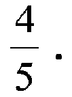
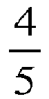
- the ratio L M L P of the width L M of a permanent magnet at the center line of the magnet and the width L P of the magnetic pole of the rotor is at least 2 3 and at most 4 5 . In degrees of electrical angle this means that the width L M of a permanent magnet at the point of the center line of the magnet ranges between 120 - 144 degrees of electrical angle.
- degrees of electrical angle refers to the angle value set by the cycle length of the fundamental frequency of the magnetic flux circulating in the air gap between the rotor and the stator. Thus 180 degrees of electrical angle is obtained for the width L P of the magnetic pole of the rotor.
- center line of a magnet refers to a ring in the direction of rotational movement of the rotor, which is situated at essentially the geometrical center point of the magnet, in other words the length of the magnet in the direction of a right angle to the center line is the same on both sides of the center line.
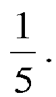
- the direction of at least one side of a permanent magnet on the rotor differs from the direction of the stator slot with a slot inclination s, the ratio s L P of which slot inclination s and the width L P of a magnetic pole of the rotor is at least 5 36 and at most 1 5 . In degrees of electrical angle this means that the slot inclination ranges between 25 - 36 degrees of electrical angle.
- the vibration and noise caused by the harmonics of the magnetic flux can be reduced, particularly in those types of electric motors in which a concentrated fractional-slot winding is fitted into the stator slots of the electric motor, the slots per pole and phase q of which winding is smaller than 0.5, most preferably 0.3.
- the aforementioned slot inclination of a permanent magnet can preferably be implemented by shaping the permanent magnets of the rotor to be essentially arrow-shaped.
- the electric motor according to the invention is preferably an axial flux motor, in which the air gap between the stator and the rotor is essentially in the direction of the axis of rotation of the rotor.
- the tip of an arrow-shaped permanent magnet on the rotor of an axial flux motor is preferably disposed farther from the axis of rotation of the rotor than the center line of the aforementioned permanent magnet.
- the permanent magnet can be shaped such that the width of the permanent magnet increases when the distance from the axis of rotation of the rotor increases.
- the shaping of the permanent magnet increases the torque of the motor, because a larger part of the magnetic flux of the motor in this case travels in a part of the electric motor that is disposed farther in the radial direction from the axis of rotation of the rotor.
- the electric motor according to the invention can also be a radial flux motor, in which the air gap between the stator and the rotor is essentially in the direction of the radius of the electric motor.
- the magnetic poles of consecutive permanent magnets in the rotor of an electric motor according to the invention are preferably of opposite directions to each other.
- the invention relates to a hoisting machine, which comprises an electric motor of the type disclosed above.
- the stator of the electric motor is preferably disposed in a stationary structure of the hoisting machine, and the rotor of the electric motor is preferably disposed in a rotating structure of the hoisting machine.
- the rotating structure of the hoisting machine comprises a traction sheave.
- the invention relates to an elevator system, which comprises any hoisting machine of the type disclosed above, for moving an elevator car in an elevator hoistway.
- the hoisting machine owing to its smaller size and quieter noise level, can be disposed preferably in the elevator hoistway.
- the rotor is disposed on a first side of the rotating structure of the hoisting machine, and the traction sheave is disposed on the opposite side of the rotating structure of the hoisting machine.
- the traction sheave is fixed to the same piece as the rotor.
- the traction sheave can be integrated into the same piece as the rotor; the hoisting machine can also comprise a fixing means, such as a bolt, for fixing and/or detaching the traction sheave. This can be a benefit e.g. if the traction sheave must be replaced because of wear or malfunction. Replacement of the traction sheave can be necessary e.g. owing to wear of the rope grooves in the surface part of the traction sheave.
- the metallization of the grooves or the coating, such as polyurethane or corresponding, of coated grooves might wear owing to, inter alia , slipping of the ropes. Also the geometry of the grooves affects the wearing.
- the traction sheave is hollow.
- the rotating structure of the hoisting machine can therefore be made to be extremely rigid, but the structure is simultaneously light and fits into a small space.
- the size of the hoisting machine can also be further reduced by disposing e.g. the machinery brake and/or the sensor that measures the movement of the rotating part of the hoisting machine inside a hollow traction sheave.
- the braking surface of the machinery brake can also be formed on the inner surface of the ring part of the hollow traction sheave.
- the rotating structure of the hoisting machine is preferably made from a material that conducts magnetic flux, at least in the immediate proximity of the permanent magnets.
- the thickness of the permanent magnets in the direction of the air gap is essentially constant; the aforementioned thickness of the permanent magnets in the direction of the air gap can, however, also vary such that with the variation in thickness it is endeavoured to achieve a density distribution of magnetic flux that is as sinusoidal as possible in the air gap of the magnetic circuit.
- the aforementioned permanent magnets of the rotor are preferably fitted into a fixing matrix, which in order to reduce eddy currents is made from a material that does not conduct electricity, or conducts electricity poorly, such as from glass fiber composite, stainless steel or corresponding.
- the permanent magnets can, however, also be fixed e.g. by embedding them into the rotating structure of the hoisting machine into recesses to be machined for this purpose.
- the rotating structure of the hoisting machine is supported on the stationary shaft of the hoisting machine via bearings.
- the shaft can also be made hollow, in which case the hoisting machine lightens without essentially weakening the rigidity of the hoisting machine.
- the hollow structure of the shaft and/or of the traction sheave also means that the amount of raw material needed for manufacturing the hoisting machine decreases.
- the sensor that measures the movement of a rotating structure of the hoisting machine can also be disposed inside the hollow shaft.
- Drum brakes or disc brakes can be used as machinery brakes of the hoisting machine according to the invention.
- the braking surface is preferably formed into a rim-like ring as an extension of the outermost ring of the rotating structure of the hoisting machine, e.g. into the brake disc of a disc brake or into the brake ring of a drum brake.
- Fig. 1 presents permanent magnets disposed consecutively on the surface of a rotor of a permanent-magnet synchronous motor according to the invention in a ring 12 in the direction of the rotational movement, presented from the direction of the air gap.
- the ring 12 in the direction of rotational movement is, for the sake of clarity, presented when straightened out, in which case the permanent magnets are disposed in a ring in the direction of rotational movement consecutively in a straight line.
- the permanent magnets are essentially arrow-shaped.
- the dimensions and placement of the permanent magnets 3a, 3b on the rotor are selected such that the ratio L M L P of the width L M of each permanent magnet 3a, 3b at the point of the center line 12 of the magnet and the width L P of the magnetic pole of the rotor is at least 2 3 and at most 4 5 . In degrees of electrical angle this means that when the width L P of a magnetic pole is 180 degrees of electrical angle, the width of a permanent magnet at the point L M of the center line 12 of the magnet ranges between 120 - 144 degrees of electrical angle.
- the motor also comprises a stator (not shown in figure), which comprises slots for the stator winding. The stator slots are disposed at a right angle with respect to the ring 12 in the direction of the rotational movement.
- a concentrated fractional-slot winding is fitted into the stator slots, the slots per pole and phase q of which winding is smaller than 0.5.
- the slots per pole and phase q indicates the number of stator slots per phase and per pole of the motor.
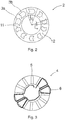
- Fig. 2 illustrates a rotor 2 of an axial flux motor according to the invention as viewed from the direction of the axis of rotation.
- the rotor 2 can be formed e.g. in the rotating piece 16 of the hoisting machine 14 of Fig. 6 such that permanent magnets 3a, 3b are fixed onto the surface of the rotating piece 16 of the hoisting machine 14 consecutively at regular intervals in a ring 12 in the direction of the rotational movement.
- the permanent magnets 3a, 3b are arrow-shaped; additionally, all the permanent magnets have the same width at the point L M of the center line of the magnet.
- the magnetic poles of two consecutive permanent magnets 3a, 3b are of opposite directions to each other, such that the strength vectors of the magnetic field produced by the consecutive permanent magnets are of opposite directions to each other.
- the dimensions and placement of the permanent magnets, as likewise the slot inclination of the permanent magnets, are according to the embodiment of Fig. 1 .
- the stator 4 of the hoisting machine of Fig. 6 comprises a concentrated fractional-slot winding, the slots per pole and phase of which winding is smaller than 0.5.
- the stator 4 is disposed in the stationary frame part 15 of the hoisting machine.
- the rotating piece 16 of the hoisting machine also comprises a traction sheave 17, which comprises rope grooves for the traction ropes.
- the stator and the rotor are disposed facing each other in the hoisting machine 14 such that an air gap 8 in the direction of the axis of rotation 9 remains between them.
- the magnetic flux of the motor passes over the air gap 8 when it rotates between the rotor 2 and the stator 4.
- Fig. 3 presents one possible stator 4 of the hoisting machine 14 of Fig. 6 .
- the stator 4 of Fig. 3 comprises 12 slots, and there are three phases in the stator winding.
- the rotor according to Fig. 2 comprises 10 poles, because each permanent magnet forms a magnetic pole in the rotor. Therefore, when using a rotor according to Fig. 2 and also a stator according to Fig. 3 , 0.4 is obtained as the slots per pole and phase of the motor.
- the slots per pole and phase is 0.3.
- the motor most preferably comprises 36 stator slots, and the number of magnetic poles of the rotor is 40. There are 40 permanent magnets, i.e. as many as there are magnetic poles.
- the permanent magnets 3a, 3b of the rotor of Fig. 2 are fitted into a fixing matrix, which is in turn fixed to the surface of a rotating piece 16 of the hoisting machine.
- the thickness of the permanent magnets in the direction of the air gap 8 is essentially constant.
- the rotating piece 16 is made from ferromagnetic material in the proximity of the permanent magnets 3a, 3b, in which material the magnetic flux flowing in the magnetic circuit circulates.
- the torque ripple of the motor is reduced by reducing the harmonics of the magnetic flux circulating in the air gap of the motor. Harmonics could also be reduced with shapes, such as polygons, that differ from or are adapted from the shape of an arrow, the width of which shapes at the point of the center line of the magnet, and the slot inclination of which shapes, are however within the scope of the limit values specified in the invention.
- One possible shape of a permanent magnet is a quadrangle, the direction of at least one side of which differs from the direction of the stator slot within the limits of slot inclination 2 presented in the invention.
- one or more corners of a permanent magnet can also be rounded.
- Fig. 4 presents one such permanent magnet, slightly adapted from the shape of an arrow, that is applicable e.g. to any of the axial flux motors described above, wherein the tip 11 of the arrow-shaped permanent magnet is disposed farther from the axis of rotation 9 of the rotor than the center line 12 that runs via the geometrical center point of the permanent magnet 3a and that is disposed in a ring in the direction of the rotational movement of the rotor.
- the center line 12 refers to such a ring in the direction of rotational movement of the rotor that is situated at essentially the geometrical center point of the magnet, in other words the length of the magnet in the direction A of a right angle to the center line is the same on both sides of the center line 12.
- the width 1 of the permanent magnet increases when the distance 10 from the axis of rotation 9 of the rotor increases in the direction of the arrow 10, in which case a larger part of the magnetic field produced by a permanent magnet is situated farther from the axis of rotation of the rotor.
- Fig. 5 illustrates a radial flux motor according to the invention as viewed from the direction of the axis of rotation.
- the permanent magnets 3a, 3b are on the surface of the rotor 2.
- the permanent magnets 3a, 3b are fixed to a fixing matrix and disposed consecutively on the surface of the rotor in a ring in the direction of the rotational movement.
- the permanent magnets 3a, 3b are essentially arrow-shaped.
- the dimensions and placement of the permanent magnets 3a, 3b on the rotor 2 are selected such that the ratio L M L P of the width of each permanent magnet 3a, 3b at the point L M of the center line 12 of the magnet and the width L P of the magnetic pole of the rotor is at least 2 3 and at most 4 5 .
- the motor also comprises a stator 4, which comprises slots 5 for the stator winding 6.
- the stator slots 5 are disposed at a right angle with respect to the ring in the direction of the rotational movement.
- the stator in Fig. 5 comprises open slot apertures, but the motor can also have semi-open or closed slot apertures.
- the direction of the sides of a permanent magnet that end in a tip, as likewise of the sides disposed on the opposite side of the permanent magnet, differs from the direction of the stator slots 5 with a slot inclination s, the ratio s L P of which slot inclination s and the width L P of a magnetic pole of the rotor is at least 5 36 and at most 1 5 . In degrees of electrical angle this means that the slot inclination s ranges between 25 - 36 degrees of electrical angle.
- a concentrated fractional-slot winding is fitted into the stator slots, the slots per pole and phase q of which winding is smaller than 0.5.
- Fig. 7 presents as a block diagram an elevator system, in which the elevator car 18 and the counterweight 20 are suspended in the elevator hoistway 19 with elevator ropes passing via the traction sheave 17 of the hoisting machine 14 of the elevator.
- the elevator car is moved by exerting a force effect on the elevator car via the hoisting ropes with the hoisting machine 14 of the elevator.
- the power supply to the hoisting machine 1 of the elevator occurs with a frequency converter (not shown in figure) connected between the electricity network and the hoisting machine 14 of the elevator.
- the frequency converter and the hoisting machine 14 of the elevator are disposed in the elevator hoistway, in connection with a wall of the elevator hoistway 19 outside the path of movement of the elevator car 18.
- the hoisting machine 14 of the elevator is of the type presented in Fig. 6 .
- the hoisting machine 14 of the elevator can therefore be made flatter in its dimension in the direction of the axis of rotation 9 than a prior-art one.
- a flatter hoisting machine 14 of an elevator enables increasing the width of the elevator car 18 in the direction of the axis of rotation 9 of the hoisting machine 1 of the elevator, in which case a more spacious elevator car 18 than before can be fitted into the same elevator hoistway.
- the placement and shaping of the rotor magnets of a hoisting machine 14 according to the invention reduces the torque ripple of the motor and makes the hoisting machine extremely quiet.
- the electric motor 1 and hoisting machine 14 according to the invention are suited for use e.g. in different conveying systems and lifting systems; in addition to a passenger elevator and freight elevator system, the electric motor 1 and hoisting machine 14 can be used e.g. in mine elevators, drum drive elevators, and also in cranes. On the other hand, the electric motor according to the invention is also suited for use in e.g. escalator systems and travelator systems.
Landscapes
- Engineering & Computer Science (AREA)
- Power Engineering (AREA)
- Civil Engineering (AREA)
- Mechanical Engineering (AREA)
- Structural Engineering (AREA)
- Automation & Control Theory (AREA)
- Cage And Drive Apparatuses For Elevators (AREA)
- Permanent Magnet Type Synchronous Machine (AREA)
- Permanent Field Magnets Of Synchronous Machinery (AREA)
- Iron Core Of Rotating Electric Machines (AREA)
Abstract


Description
- The invention relates to the structures of electric motors and more particularly to the structures of permanent-magnet motors.
- It is a general aim to utilize built space as efficiently as possible. For example, owing to space requirements, one aim is to make the hoisting machines of elevators as compact as possible. In order to achieve this, hoisting machines are designed to be as flat as possible in their dimensions in the direction of the axis of rotation, in which case the hoisting machines fit better in connection with, for instance, the wall part of the elevator hoistway or into some other corresponding narrow space. On the other hand, the aim in some solutions has been to design the hoisting machine so as to be as small as possible in its dimensions in the radial direction, such that the hoisting machine fits better e.g. in connection with the top end or the bottom end of the elevator hoistway.
- In recent times permanent-magnet motors have started to be used in the electric motors of hoisting machines, which permanent-magnet motors comprise a concentrated stator winding that is wound into two adjacent slots around the stator tooth. In a concentrated winding the proportion of the winding overhang remains shorter than in a conventional diamond winding, in which case the size of the hoisting machine also decreases.
- The use of a concentrated winding, however, causes problems. The density distribution of the magnetic flux produced by a concentrated winding in the air gap of an electric motor differs significantly from sinusoidal, and therefore contains a lot of harmonics. Harmonics, on the other hand, produce vibration and disturbing noise in a motor.
- To remedy this disadvantage it is known in prior art as for example from document
JP 2000134893 Document EP 2 101 395 A2 in turn speaks of that a salient pole machine then also ends up in increased torque ripples when the reluctance torque is made too high because of needing a high torque for the motor as such. So, it is proposed to apply a specific rate of θpm/θr being 0.65 ≤ θpm/θr ≤ 0.85, wherein θpm is an angle of a permanent magnet in shape, and θr is an angle of one magnetic pole. - The aim of the invention is to present a permanent-magnet motor, in which the vibration and noise caused by the harmonics of the magnetic field is reduced by developing the placement and the shape of the permanent magnets. To achieve this aim the invention discloses an electric motor according to
claim 1, a hoisting machine according toclaim 10, and also an elevator system according toclaim 12. The preferred embodiments of the invention are described in the non-independent claims. - The electric motor according to the invention comprises a stator, which stator comprises slots, into which slots a concentrated winding is fitted. The electric motor also comprises a rotating rotor, which rotor comprises permanent magnets placed consecutively in a ring in the direction of the rotational movement. The ratio


- In a preferred embodiment of the invention the direction of at least one side of a permanent magnet on the rotor differs from the direction of the stator slot with a slot inclination s, the ratio


- By means of the placement of the rotor magnets and of the shaping of the magnet, as presented above, the vibration and noise caused by the harmonics of the magnetic flux can be reduced, particularly in those types of electric motors in which a concentrated fractional-slot winding is fitted into the stator slots of the electric motor, the slots per pole and phase q of which winding is smaller than 0.5, most preferably 0.3. The aforementioned slot inclination of a permanent magnet can preferably be implemented by shaping the permanent magnets of the rotor to be essentially arrow-shaped.
- The electric motor according to the invention is preferably an axial flux motor, in which the air gap between the stator and the rotor is essentially in the direction of the axis of rotation of the rotor. The tip of an arrow-shaped permanent magnet on the rotor of an axial flux motor is preferably disposed farther from the axis of rotation of the rotor than the center line of the aforementioned permanent magnet. The permanent magnet can be shaped such that the width of the permanent magnet increases when the distance from the axis of rotation of the rotor increases. In this case the shaping of the permanent magnet increases the torque of the motor, because a larger part of the magnetic flux of the motor in this case travels in a part of the electric motor that is disposed farther in the radial direction from the axis of rotation of the rotor. The electric motor according to the invention can also be a radial flux motor, in which the air gap between the stator and the rotor is essentially in the direction of the radius of the electric motor.
- The magnetic poles of consecutive permanent magnets in the rotor of an electric motor according to the invention are preferably of opposite directions to each other.
- With regard to the second aspect the invention relates to a hoisting machine, which comprises an electric motor of the type disclosed above. In the hoisting machine the stator of the electric motor is preferably disposed in a stationary structure of the hoisting machine, and the rotor of the electric motor is preferably disposed in a rotating structure of the hoisting machine. The rotating structure of the hoisting machine comprises a traction sheave. When using an electric motor according to the invention, the vibration and noise of the hoisting machine can be reduced.
- With regard to the third aspect, the invention relates to an elevator system, which comprises any hoisting machine of the type disclosed above, for moving an elevator car in an elevator hoistway. In an elevator system according to the invention, the hoisting machine, owing to its smaller size and quieter noise level, can be disposed preferably in the elevator hoistway.
- In a preferred embodiment of the invention the rotor is disposed on a first side of the rotating structure of the hoisting machine, and the traction sheave is disposed on the opposite side of the rotating structure of the hoisting machine. The traction sheave is fixed to the same piece as the rotor. The traction sheave can be integrated into the same piece as the rotor; the hoisting machine can also comprise a fixing means, such as a bolt, for fixing and/or detaching the traction sheave. This can be a benefit e.g. if the traction sheave must be replaced because of wear or malfunction. Replacement of the traction sheave can be necessary e.g. owing to wear of the rope grooves in the surface part of the traction sheave. The metallization of the grooves or the coating, such as polyurethane or corresponding, of coated grooves might wear owing to, inter alia, slipping of the ropes. Also the geometry of the grooves affects the wearing.
- In a preferred embodiment of the invention, the traction sheave is hollow. The rotating structure of the hoisting machine can therefore be made to be extremely rigid, but the structure is simultaneously light and fits into a small space. The size of the hoisting machine can also be further reduced by disposing e.g. the machinery brake and/or the sensor that measures the movement of the rotating part of the hoisting machine inside a hollow traction sheave. The braking surface of the machinery brake can also be formed on the inner surface of the ring part of the hollow traction sheave.
- The rotating structure of the hoisting machine is preferably made from a material that conducts magnetic flux, at least in the immediate proximity of the permanent magnets. In a preferred embodiment of the invention the thickness of the permanent magnets in the direction of the air gap is essentially constant; the aforementioned thickness of the permanent magnets in the direction of the air gap can, however, also vary such that with the variation in thickness it is endeavoured to achieve a density distribution of magnetic flux that is as sinusoidal as possible in the air gap of the magnetic circuit.
- The aforementioned permanent magnets of the rotor are preferably fitted into a fixing matrix, which in order to reduce eddy currents is made from a material that does not conduct electricity, or conducts electricity poorly, such as from glass fiber composite, stainless steel or corresponding. The permanent magnets can, however, also be fixed e.g. by embedding them into the rotating structure of the hoisting machine into recesses to be machined for this purpose.
- In a preferred embodiment of the invention, the rotating structure of the hoisting machine is supported on the stationary shaft of the hoisting machine via bearings. The shaft can also be made hollow, in which case the hoisting machine lightens without essentially weakening the rigidity of the hoisting machine. The hollow structure of the shaft and/or of the traction sheave also means that the amount of raw material needed for manufacturing the hoisting machine decreases. The sensor that measures the movement of a rotating structure of the hoisting machine can also be disposed inside the hollow shaft.
- Drum brakes or disc brakes, for example, can be used as machinery brakes of the hoisting machine according to the invention. The braking surface is preferably formed into a rim-like ring as an extension of the outermost ring of the rotating structure of the hoisting machine, e.g. into the brake disc of a disc brake or into the brake ring of a drum brake.
- The aforementioned summary, as well as the additional features and advantages of the invention presented below, will be better understood by the aid of the following description of some embodiments, said description not limiting the scope of application of the invention.
-
- Fig. 1
- illustrates the placement of permanent magnets on the surface of the rotor
- Fig. 2
- illustrates a rotor of an axial flux motor according to the invention as viewed from the direction of the axis of rotation
- Fig. 3
- illustrates a stator of an axial flux motor according to the invention as viewed from the direction of the axis of rotation
- Fig. 4
- illustrates a permanent magnet of an axial flux motor according to the invention as viewed from the direction of the air gap
- Fig. 5
- illustrates a radial flux motor according to the invention as viewed from the direction of the axis of rotation
- Fig. 6
- presents a part of one hoisting machine according to the invention, sectioned open upwards from the axis of rotation of the hoisting machine in the direction of the radius
- Fig. 7
- presents an elevator system according to the invention, as a block diagram
-
Fig. 1 presents permanent magnets disposed consecutively on the surface of a rotor of a permanent-magnet synchronous motor according to the invention in aring 12 in the direction of the rotational movement, presented from the direction of the air gap. InFig. 1 thering 12 in the direction of rotational movement is, for the sake of clarity, presented when straightened out, in which case the permanent magnets are disposed in a ring in the direction of rotational movement consecutively in a straight line. The permanent magnets are essentially arrow-shaped. The dimensions and placement of thepermanent magnets 
permanent magnet center line 12 of the magnet and the width LP of the magnetic pole of the rotor is at least

center line 12 of the magnet ranges between 120 - 144 degrees of electrical angle. The motor also comprises a stator (not shown in figure), which comprises slots for the stator winding. The stator slots are disposed at a right angle with respect to thering 12 in the direction of the rotational movement. The direction of the sides of a permanent magnet that end in atip 11, as likewise of thesides 7 disposed on the opposite side of the permanent magnet, differs from the direction of the stator slots with a slot inclination s, the ratio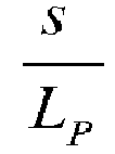


-
Fig. 2 illustrates arotor 2 of an axial flux motor according to the invention as viewed from the direction of the axis of rotation. Therotor 2 can be formed e.g. in therotating piece 16 of the hoistingmachine 14 ofFig. 6 such thatpermanent magnets rotating piece 16 of the hoistingmachine 14 consecutively at regular intervals in aring 12 in the direction of the rotational movement. Thepermanent magnets permanent magnets Fig. 1 . Thestator 4 of the hoisting machine ofFig. 6 comprises a concentrated fractional-slot winding, the slots per pole and phase of which winding is smaller than 0.5. Thestator 4 is disposed in thestationary frame part 15 of the hoisting machine. The rotatingpiece 16 of the hoisting machine also comprises atraction sheave 17, which comprises rope grooves for the traction ropes. The stator and the rotor are disposed facing each other in the hoistingmachine 14 such that anair gap 8 in the direction of the axis ofrotation 9 remains between them. The magnetic flux of the motor passes over theair gap 8 when it rotates between therotor 2 and thestator 4. -
Fig. 3 presents onepossible stator 4 of the hoistingmachine 14 ofFig. 6 . Thestator 4 ofFig. 3 comprises 12 slots, and there are three phases in the stator winding. The rotor according toFig. 2 , on the other hand, comprises 10 poles, because each permanent magnet forms a magnetic pole in the rotor. Therefore, when using a rotor according toFig. 2 and also a stator according toFig. 3 , 0.4 is obtained as the slots per pole and phase of the motor. In a preferred embodiment of the invention the slots per pole and phase is 0.3. In this case the motor most preferably comprises 36 stator slots, and the number of magnetic poles of the rotor is 40. There are 40 permanent magnets, i.e. as many as there are magnetic poles. - The
permanent magnets Fig. 2 are fitted into a fixing matrix, which is in turn fixed to the surface of arotating piece 16 of the hoisting machine. The thickness of the permanent magnets in the direction of theair gap 8 is essentially constant. The rotatingpiece 16 is made from ferromagnetic material in the proximity of thepermanent magnets - With the shaping and placement according to the invention of the
permanent magnets slot inclination 2 presented in the invention. On the other hand one or more corners of a permanent magnet can also be rounded. -
Fig. 4 presents one such permanent magnet, slightly adapted from the shape of an arrow, that is applicable e.g. to any of the axial flux motors described above, wherein thetip 11 of the arrow-shaped permanent magnet is disposed farther from the axis ofrotation 9 of the rotor than thecenter line 12 that runs via the geometrical center point of thepermanent magnet 3a and that is disposed in a ring in the direction of the rotational movement of the rotor. Thecenter line 12 refers to such a ring in the direction of rotational movement of the rotor that is situated at essentially the geometrical center point of the magnet, in other words the length of the magnet in the direction A of a right angle to the center line is the same on both sides of thecenter line 12. In addition, thewidth 1 of the permanent magnet increases when thedistance 10 from the axis ofrotation 9 of the rotor increases in the direction of thearrow 10, in which case a larger part of the magnetic field produced by a permanent magnet is situated farther from the axis of rotation of the rotor. With this type of shaping of the permanent magnet, the torque production of a motor can be improved. -
Fig. 5 illustrates a radial flux motor according to the invention as viewed from the direction of the axis of rotation. Thepermanent magnets rotor 2. Thepermanent magnets permanent magnets permanent magnets rotor 2 are selected such that the ratio
permanent magnet center line 12 of the magnet and the width LP of the magnetic pole of the rotor is at least
center line 12 of the magnet ranges between 120 - 144 degrees of electrical angle. The motor also comprises astator 4, which comprisesslots 5 for the stator winding 6. Thestator slots 5 are disposed at a right angle with respect to the ring in the direction of the rotational movement. The stator inFig. 5 comprises open slot apertures, but the motor can also have semi-open or closed slot apertures. The direction of the sides of a permanent magnet that end in a tip, as likewise of the sides disposed on the opposite side of the permanent magnet, differs from the direction of thestator slots 5 with a slot inclination s, the ratio


-
Fig. 7 presents as a block diagram an elevator system, in which theelevator car 18 and thecounterweight 20 are suspended in theelevator hoistway 19 with elevator ropes passing via thetraction sheave 17 of the hoistingmachine 14 of the elevator. The elevator car is moved by exerting a force effect on the elevator car via the hoisting ropes with the hoistingmachine 14 of the elevator. The power supply to the hoistingmachine 1 of the elevator occurs with a frequency converter (not shown in figure) connected between the electricity network and the hoistingmachine 14 of the elevator. The frequency converter and the hoistingmachine 14 of the elevator are disposed in the elevator hoistway, in connection with a wall of theelevator hoistway 19 outside the path of movement of theelevator car 18. The hoistingmachine 14 of the elevator is of the type presented inFig. 6 . As a result of the concentrated fractional-slot winding, the hoistingmachine 14 of the elevator can therefore be made flatter in its dimension in the direction of the axis ofrotation 9 than a prior-art one. As can be observed fromFig. 7 , aflatter hoisting machine 14 of an elevator enables increasing the width of theelevator car 18 in the direction of the axis ofrotation 9 of the hoistingmachine 1 of the elevator, in which case a morespacious elevator car 18 than before can be fitted into the same elevator hoistway. Likewise the placement and shaping of the rotor magnets of a hoistingmachine 14 according to the invention reduces the torque ripple of the motor and makes the hoisting machine extremely quiet. - The
electric motor 1 and hoistingmachine 14 according to the invention are suited for use e.g. in different conveying systems and lifting systems; in addition to a passenger elevator and freight elevator system, theelectric motor 1 and hoistingmachine 14 can be used e.g. in mine elevators, drum drive elevators, and also in cranes. On the other hand, the electric motor according to the invention is also suited for use in e.g. escalator systems and travelator systems. - The invention is not only limited to be applied to the embodiments described above, but instead many variations are possible within the scope of the inventive concept defined by the claims below.
Claims (13)
- Electric motor (1), which comprises a stator (4);
which stator comprises slots (5), into which slots a concentrated winding (6) is fitted;
and which electric motor comprises a rotating rotor (2); which rotor (2) comprises permanent magnets (3a, 3b) placed consecutively in a ring (12) in the direction of the rotational movement;
wherein the ratio



- Electric motor according to claim 1, characterized in that the concentrated winding is a concentrated fractional-slot winding (6).
- Electric motor according to claim 2, characterized in that the slots per pole and phase (q) of the concentrated fractional-slot winding (6) is smaller than 0.5.
- Electric motor according to any of claims 1 - 3, characterized in that the air gap (8) between the stator (4) and the rotor (2) is essentially in the direction of the axis of rotation (9) of the rotor.
- Electric motor according to claim 4, characterized in that the width (1) of the permanent magnet (3a, 3b) increases when the distance (10) from the axis of rotation (9) of the rotor increases.
- Electric motor according to any of the preceding claims, characterized in that the permanent magnet (3a, 3b) of the rotor is essentially arrow-shaped.
- Electric motor according to claim 6, characterized in that the tip (11) of the arrow-shaped permanent magnet (3a, 3b) on the rotor is disposed farther from the axis of rotation (9) of the rotor than the center line (12) of the aforementioned permanent magnet (3a, 3b).
- Electric motor according to any of the preceding claims, characterized in that the magnetic poles of consecutive permanent magnets (3a, 3b) are of opposite directions to each other.
- Electric motor according to any of the preceding claims, characterized in that the thickness of a permanent magnet (13) in the direction of the air gap is essentially constant.
- Hoisting machine (14), characterized in that the hoisting machine comprises an electric motor (1) according to any of claims 1 - 9.
- Hoisting machine according to claim 10, characterized in that the stator (4) of the electric motor is disposed in a stationary structure (15) of the hoisting machine;
and in that the rotor (2) of the electric motor is disposed in a rotating structure (16) of the hoisting machine;
and in that the rotating structure (16) of the hoisting machine comprises a traction sheave (17). - Elevator system, characterized in that the elevator system comprises a hoisting machine (14) according to claim 10 or 11, for moving an elevator car (18) in an elevator hoistway (19).
- Elevator system according to claim 12, characterized in that the hoisting machine (14) is disposed in the elevator hoistway (19).
Applications Claiming Priority (3)
| Application Number | Priority Date | Filing Date | Title |
|---|---|---|---|
| FI20105339A FI122696B (en) | 2010-03-31 | 2010-03-31 | Electric motor, elevator machinery and lift system |
| PCT/FI2011/050270 WO2011121184A1 (en) | 2010-03-31 | 2011-03-30 | Electric motor, hoisting machine and elevator system |
| EP11762077.3A EP2553793B1 (en) | 2010-03-31 | 2011-03-30 | Electric motor, hoisting machine and elevator system |
Related Parent Applications (2)
| Application Number | Title | Priority Date | Filing Date |
|---|---|---|---|
| EP11762077.3A Division-Into EP2553793B1 (en) | 2010-03-31 | 2011-03-30 | Electric motor, hoisting machine and elevator system |
| EP11762077.3A Division EP2553793B1 (en) | 2010-03-31 | 2011-03-30 | Electric motor, hoisting machine and elevator system |
Publications (2)
| Publication Number | Publication Date |
|---|---|
| EP3176914A1 true EP3176914A1 (en) | 2017-06-07 |
| EP3176914B1 EP3176914B1 (en) | 2024-10-16 |
Family
ID=42074440
Family Applications (2)
| Application Number | Title | Priority Date | Filing Date |
|---|---|---|---|
| EP11762077.3A Active EP2553793B1 (en) | 2010-03-31 | 2011-03-30 | Electric motor, hoisting machine and elevator system |
| EP16201433.6A Active EP3176914B1 (en) | 2010-03-31 | 2011-03-30 | Electric motor, hoisting machine and elevator system |
Family Applications Before (1)
| Application Number | Title | Priority Date | Filing Date |
|---|---|---|---|
| EP11762077.3A Active EP2553793B1 (en) | 2010-03-31 | 2011-03-30 | Electric motor, hoisting machine and elevator system |
Country Status (11)
| Country | Link |
|---|---|
| US (2) | US8698368B2 (en) |
| EP (2) | EP2553793B1 (en) |
| JP (2) | JP5975980B2 (en) |
| CN (1) | CN102859842B (en) |
| BR (1) | BR112012024457B1 (en) |
| ES (1) | ES2913478T3 (en) |
| FI (1) | FI122696B (en) |
| MX (1) | MX2012010139A (en) |
| MY (1) | MY157128A (en) |
| RU (1) | RU2566254C2 (en) |
| WO (1) | WO2011121184A1 (en) |
Cited By (1)
| Publication number | Priority date | Publication date | Assignee | Title |
|---|---|---|---|---|
| EP4485756A1 (en) * | 2023-06-27 | 2025-01-01 | dormakaba Deutschland GmbH | Permanent magnet assembly for an axial flux machine of a door drive and axial flux machine |
Families Citing this family (17)
| Publication number | Priority date | Publication date | Assignee | Title |
|---|---|---|---|---|
| US9742228B2 (en) | 2013-10-18 | 2017-08-22 | General Electric Company | Torque ripple reduction in electric machines |
| KR101724471B1 (en) * | 2015-05-26 | 2017-04-18 | 현대자동차 주식회사 | Alternator unit having vibration reducing damper |
| US20170016449A1 (en) * | 2015-07-14 | 2017-01-19 | Hamilton Sundstrand Corporation | Axial-flux induction motor pump |
| CN106972653A (en) * | 2016-01-14 | 2017-07-21 | 德昌电机(深圳)有限公司 | Motor and its outer magnetic core, inner magnetic core |
| JP2017169343A (en) | 2016-03-16 | 2017-09-21 | 株式会社東芝 | Rotating electric machines, hoisting machines, and elevators |
| US11053996B2 (en) * | 2016-07-15 | 2021-07-06 | Qiguang Wang | Hub motor |
| US10256708B2 (en) | 2016-09-22 | 2019-04-09 | General Electric Company | Electric machine |
| RU172408U1 (en) * | 2016-11-22 | 2017-07-07 | Закрытое Акционерное Общество "Научно-Исследовательский Институт Механотронных Технологий - Альфа - Научный Центр" | Non-contact dc motor |
| RU2660945C2 (en) * | 2016-12-05 | 2018-07-11 | Федеральное государственное бюджетное образовательное учреждение высшего образования "Омский государственный технический университет" | Magnetoelectric machine |
| CN108880030A (en) * | 2017-05-12 | 2018-11-23 | 蒂森克虏伯电梯(上海)有限公司 | Capstan rotor and traction machine with the rotor |
| CN109368466A (en) * | 2018-10-25 | 2019-02-22 | 贵州高矿重工(长顺)有限公司 | A kind of magneto built-in type mine hoist |
| CN113131644A (en) * | 2019-12-31 | 2021-07-16 | 日本电产株式会社 | Rotor core and motor having the same |
| DE102020125121A1 (en) * | 2020-09-25 | 2022-03-31 | Dormakaba Deutschland Gmbh | Drive device for moving a wing |
| DE102021113660A1 (en) | 2021-05-27 | 2022-12-01 | Schaeffler Technologies AG & Co. KG | Axial flux electric machine, collaborative robot with an axial flux electric machine |
| CN119095785A (en) * | 2022-05-10 | 2024-12-06 | 通力股份公司 | Elevator Motor |
| WO2024054859A1 (en) | 2022-09-06 | 2024-03-14 | Harbinger Motors Inc. | Fractional-slot-winding motors and electrical vehicles comprising thereof |
| CN117914090A (en) * | 2022-10-12 | 2024-04-19 | 通用汽车环球科技运作有限责任公司 | Axial flux electric machine including skewed poles |
Citations (4)
| Publication number | Priority date | Publication date | Assignee | Title |
|---|---|---|---|---|
| US5783895A (en) * | 1994-04-07 | 1998-07-21 | Kone Oy | Elevator motor with flat construction |
| JP2000134893A (en) | 1998-10-29 | 2000-05-12 | Hitachi Ltd | Brushless motor |
| US20090184602A1 (en) * | 2004-09-22 | 2009-07-23 | Siemens Aktiengesellschaft | Permanent-Magnet Synchronous Machine with Suppression Means for Improving the Torque Ripple |
| EP2101395A2 (en) | 2008-03-13 | 2009-09-16 | Hitachi Ltd. | Permanent magnet type generator and hybrid vehicle using the same |
Family Cites Families (17)
| Publication number | Priority date | Publication date | Assignee | Title |
|---|---|---|---|---|
| US4508998A (en) * | 1981-02-09 | 1985-04-02 | David H. Rush | Brushless disc-type DC motor or generator |
| US4642502A (en) | 1986-04-24 | 1987-02-10 | General Motors Corporation | Dynamoelectric machine with permanent magnet and magnet mounting surface arrangement |
| JP2783546B2 (en) * | 1988-05-11 | 1998-08-06 | 株式会社東芝 | Brushless motor |
| FI112296B (en) * | 1995-03-24 | 2003-11-14 | Kone Corp | Lift motor damping winding |
| JP3274597B2 (en) * | 1995-12-28 | 2002-04-15 | ミネベア株式会社 | Pulse generator |
| FI981022L (en) * | 1998-05-08 | 1999-11-09 | Juha Pyrhoenen | Permanent magnet synchronous machine structure |
| JP2000333391A (en) | 1999-05-19 | 2000-11-30 | Hitachi Ltd | Permanent magnet type rotating electric machine |
| RU24680U1 (en) * | 2001-12-21 | 2002-08-20 | Красоченков Дмитрий Федорович | LIFTING MECHANISM |
| JP2004015880A (en) * | 2002-06-05 | 2004-01-15 | Hitachi Ltd | Permanent magnet type synchronous motor and elevator apparatus using the same |
| RU2256276C2 (en) * | 2003-07-15 | 2005-07-10 | Санкт-Петербургский государственный морской технический университет | Butt-end momentum motor |
| JP3638944B1 (en) * | 2004-02-04 | 2005-04-13 | 山洋電気株式会社 | Method for determining pole arc ratio of rotary motor with built-in permanent magnet and rotary motor with built-in permanent magnet |
| DE102004056210A1 (en) * | 2004-11-22 | 2006-06-01 | Siemens Ag | Rotary linear drive with axialkraftfreien rotary drive |
| CN100576701C (en) * | 2004-11-30 | 2009-12-30 | 株式会社日立制作所 | Permanent Magnet Rotary Motor |
| JP4720982B2 (en) * | 2005-04-20 | 2011-07-13 | 株式会社富士通ゼネラル | Axial air gap type electric motor |
| CN101074077A (en) | 2006-05-19 | 2007-11-21 | 沈阳博林特电梯有限公司 | Tracking-driven elevator system |
| FI119748B (en) * | 2006-12-21 | 2009-02-27 | Kone Corp | Electric motor |
| FI120781B (en) * | 2007-09-21 | 2010-02-26 | Kone Corp | Electric motor |
-
2010
- 2010-03-31 FI FI20105339A patent/FI122696B/en active IP Right Grant
-
2011
- 2011-03-30 RU RU2012139084/07A patent/RU2566254C2/en active
- 2011-03-30 JP JP2013501882A patent/JP5975980B2/en active Active
- 2011-03-30 EP EP11762077.3A patent/EP2553793B1/en active Active
- 2011-03-30 WO PCT/FI2011/050270 patent/WO2011121184A1/en not_active Ceased
- 2011-03-30 MY MYPI2012003914A patent/MY157128A/en unknown
- 2011-03-30 ES ES11762077T patent/ES2913478T3/en active Active
- 2011-03-30 BR BR112012024457A patent/BR112012024457B1/en active IP Right Grant
- 2011-03-30 MX MX2012010139A patent/MX2012010139A/en active IP Right Grant
- 2011-03-30 CN CN201180017197.4A patent/CN102859842B/en active Active
- 2011-03-30 EP EP16201433.6A patent/EP3176914B1/en active Active
-
2012
- 2012-09-05 US US13/604,406 patent/US8698368B2/en active Active
-
2013
- 2013-11-25 US US14/089,299 patent/US9209657B2/en active Active
-
2016
- 2016-04-07 JP JP2016077183A patent/JP2016165222A/en active Pending
Patent Citations (4)
| Publication number | Priority date | Publication date | Assignee | Title |
|---|---|---|---|---|
| US5783895A (en) * | 1994-04-07 | 1998-07-21 | Kone Oy | Elevator motor with flat construction |
| JP2000134893A (en) | 1998-10-29 | 2000-05-12 | Hitachi Ltd | Brushless motor |
| US20090184602A1 (en) * | 2004-09-22 | 2009-07-23 | Siemens Aktiengesellschaft | Permanent-Magnet Synchronous Machine with Suppression Means for Improving the Torque Ripple |
| EP2101395A2 (en) | 2008-03-13 | 2009-09-16 | Hitachi Ltd. | Permanent magnet type generator and hybrid vehicle using the same |
Cited By (1)
| Publication number | Priority date | Publication date | Assignee | Title |
|---|---|---|---|---|
| EP4485756A1 (en) * | 2023-06-27 | 2025-01-01 | dormakaba Deutschland GmbH | Permanent magnet assembly for an axial flux machine of a door drive and axial flux machine |
Also Published As
| Publication number | Publication date |
|---|---|
| JP2013523559A (en) | 2013-06-17 |
| EP2553793B1 (en) | 2022-05-04 |
| EP2553793A1 (en) | 2013-02-06 |
| RU2566254C2 (en) | 2015-10-20 |
| MY157128A (en) | 2016-05-13 |
| BR112012024457B1 (en) | 2020-01-14 |
| EP3176914B1 (en) | 2024-10-16 |
| JP5975980B2 (en) | 2016-08-23 |
| CN102859842B (en) | 2015-09-09 |
| US20140076668A1 (en) | 2014-03-20 |
| CN102859842A (en) | 2013-01-02 |
| FI122696B (en) | 2012-05-31 |
| HK1178692A1 (en) | 2013-09-13 |
| JP2016165222A (en) | 2016-09-08 |
| US9209657B2 (en) | 2015-12-08 |
| ES2913478T3 (en) | 2022-06-02 |
| FI20105339A0 (en) | 2010-03-31 |
| FI20105339L (en) | 2011-10-01 |
| BR112012024457A2 (en) | 2016-05-31 |
| RU2012139084A (en) | 2014-05-10 |
| US20130015020A1 (en) | 2013-01-17 |
| MX2012010139A (en) | 2012-11-23 |
| WO2011121184A1 (en) | 2011-10-06 |
| EP2553793A4 (en) | 2016-07-06 |
| US8698368B2 (en) | 2014-04-15 |
Similar Documents
| Publication | Publication Date | Title |
|---|---|---|
| EP3176914B1 (en) | Electric motor, hoisting machine and elevator system | |
| EP2092630B1 (en) | Method of manufacturing an electric motor | |
| JP4195097B2 (en) | Elevator hoist and elevator | |
| CN102471028B (en) | Elevator machine with outer rotor and motor inside traction sheave | |
| EP3210925B1 (en) | Elevator assembly | |
| JP2013523559A5 (en) | ||
| WO2011080390A1 (en) | Hoisting machine, elevator system, and method | |
| CN114829286B (en) | Hoist and elevator | |
| CN104852482B (en) | Concentratred winding permanent magnet motor, elevator hoist and elevator using it | |
| HK1178692B (en) | Electric motor, hoisting machine and elevator system | |
| CN111183566A (en) | Rotating electrical machine and elevator hoist system | |
| JP4388315B2 (en) | Rotating electrical machine and elevator hoist apparatus using the rotating electrical machine | |
| CN119095785A (en) | Elevator Motor | |
| KR20000031329A (en) | Winch for elevator | |
| HK1171001B (en) | Elevator machine with external rotor and motor within traction sheave | |
| WO2009047383A1 (en) | Electric motor | |
| MXPA99006892A (en) | Elevator drive machine |
Legal Events
| Date | Code | Title | Description |
|---|---|---|---|
| AC | Divisional application: reference to earlier application |
Ref document number: 2553793 Country of ref document: EP Kind code of ref document: P |
|
| AK | Designated contracting states |
Kind code of ref document: A1 Designated state(s): AL AT BE BG CH CY CZ DE DK EE ES FI FR GB GR HR HU IE IS IT LI LT LU LV MC MK MT NL NO PL PT RO RS SE SI SK SM TR |
|
| AX | Request for extension of the european patent |
Extension state: BA ME |
|
| PUAI | Public reference made under article 153(3) epc to a published international application that has entered the european phase |
Free format text: ORIGINAL CODE: 0009012 |
|
| STAA | Information on the status of an ep patent application or granted ep patent |
Free format text: STATUS: THE APPLICATION HAS BEEN PUBLISHED |
|
| STAA | Information on the status of an ep patent application or granted ep patent |
Free format text: STATUS: REQUEST FOR EXAMINATION WAS MADE |
|
| 17P | Request for examination filed |
Effective date: 20171017 |
|
| RBV | Designated contracting states (corrected) |
Designated state(s): AL AT BE BG CH CY CZ DE DK EE ES FI FR GB GR HR HU IE IS IT LI LT LU LV MC MK MT NL NO PL PT RO RS SE SI SK SM TR |
|
| STAA | Information on the status of an ep patent application or granted ep patent |
Free format text: STATUS: EXAMINATION IS IN PROGRESS |
|
| 17Q | First examination report despatched |
Effective date: 20210625 |
|
| P01 | Opt-out of the competence of the unified patent court (upc) registered |
Effective date: 20230525 |
|
| REG | Reference to a national code |
Ref legal event code: R079 Free format text: PREVIOUS MAIN CLASS: H02K0001270000 Ipc: B66B0011000000 Ref country code: DE Ref legal event code: R079 Ref document number: 602011075043 Country of ref document: DE Free format text: PREVIOUS MAIN CLASS: H02K0001270000 Ipc: B66B0011000000 |
|
| GRAP | Despatch of communication of intention to grant a patent |
Free format text: ORIGINAL CODE: EPIDOSNIGR1 |
|
| STAA | Information on the status of an ep patent application or granted ep patent |
Free format text: STATUS: GRANT OF PATENT IS INTENDED |
|
| RIC1 | Information provided on ipc code assigned before grant |
Ipc: H02K 1/2795 20220101ALI20240521BHEP Ipc: H02K 7/10 20060101ALI20240521BHEP Ipc: H02K 1/14 20060101ALI20240521BHEP Ipc: H02K 1/08 20060101ALI20240521BHEP Ipc: H02K 21/24 20060101ALI20240521BHEP Ipc: B66B 11/04 20060101ALI20240521BHEP Ipc: B66B 11/00 20060101AFI20240521BHEP |
|
| INTG | Intention to grant announced |
Effective date: 20240618 |
|
| GRAS | Grant fee paid |
Free format text: ORIGINAL CODE: EPIDOSNIGR3 |
|
| GRAA | (expected) grant |
Free format text: ORIGINAL CODE: 0009210 |
|
| STAA | Information on the status of an ep patent application or granted ep patent |
Free format text: STATUS: THE PATENT HAS BEEN GRANTED |
|
| AC | Divisional application: reference to earlier application |
Ref document number: 2553793 Country of ref document: EP Kind code of ref document: P |
|
| AK | Designated contracting states |
Kind code of ref document: B1 Designated state(s): AL AT BE BG CH CY CZ DE DK EE ES FI FR GB GR HR HU IE IS IT LI LT LU LV MC MK MT NL NO PL PT RO RS SE SI SK SM TR |
|
| REG | Reference to a national code |
Ref country code: GB Ref legal event code: FG4D |
|
| REG | Reference to a national code |
Ref country code: CH Ref legal event code: EP |
|
| REG | Reference to a national code |
Ref country code: IE Ref legal event code: FG4D |
|
| REG | Reference to a national code |
Ref country code: DE Ref legal event code: R096 Ref document number: 602011075043 Country of ref document: DE |
|
| REG | Reference to a national code |
Ref country code: LT Ref legal event code: MG9D |
|
| REG | Reference to a national code |
Ref country code: NL Ref legal event code: MP Effective date: 20241016 |
|
| REG | Reference to a national code |
Ref country code: AT Ref legal event code: MK05 Ref document number: 1732786 Country of ref document: AT Kind code of ref document: T Effective date: 20241016 |
|
| PG25 | Lapsed in a contracting state [announced via postgrant information from national office to epo] |
Ref country code: NL Free format text: LAPSE BECAUSE OF FAILURE TO SUBMIT A TRANSLATION OF THE DESCRIPTION OR TO PAY THE FEE WITHIN THE PRESCRIBED TIME-LIMIT Effective date: 20241016 |
|
| PG25 | Lapsed in a contracting state [announced via postgrant information from national office to epo] |
Ref country code: NL Free format text: LAPSE BECAUSE OF FAILURE TO SUBMIT A TRANSLATION OF THE DESCRIPTION OR TO PAY THE FEE WITHIN THE PRESCRIBED TIME-LIMIT Effective date: 20241016 |
|
| PG25 | Lapsed in a contracting state [announced via postgrant information from national office to epo] |
Ref country code: PT Free format text: LAPSE BECAUSE OF FAILURE TO SUBMIT A TRANSLATION OF THE DESCRIPTION OR TO PAY THE FEE WITHIN THE PRESCRIBED TIME-LIMIT Effective date: 20250217 Ref country code: HR Free format text: LAPSE BECAUSE OF FAILURE TO SUBMIT A TRANSLATION OF THE DESCRIPTION OR TO PAY THE FEE WITHIN THE PRESCRIBED TIME-LIMIT Effective date: 20241016 Ref country code: IS Free format text: LAPSE BECAUSE OF FAILURE TO SUBMIT A TRANSLATION OF THE DESCRIPTION OR TO PAY THE FEE WITHIN THE PRESCRIBED TIME-LIMIT Effective date: 20250216 |
|
| PG25 | Lapsed in a contracting state [announced via postgrant information from national office to epo] |
Ref country code: FI Free format text: LAPSE BECAUSE OF FAILURE TO SUBMIT A TRANSLATION OF THE DESCRIPTION OR TO PAY THE FEE WITHIN THE PRESCRIBED TIME-LIMIT Effective date: 20241016 |
|
| PG25 | Lapsed in a contracting state [announced via postgrant information from national office to epo] |
Ref country code: BG Free format text: LAPSE BECAUSE OF FAILURE TO SUBMIT A TRANSLATION OF THE DESCRIPTION OR TO PAY THE FEE WITHIN THE PRESCRIBED TIME-LIMIT Effective date: 20241016 |
|
| PG25 | Lapsed in a contracting state [announced via postgrant information from national office to epo] |
Ref country code: ES Free format text: LAPSE BECAUSE OF FAILURE TO SUBMIT A TRANSLATION OF THE DESCRIPTION OR TO PAY THE FEE WITHIN THE PRESCRIBED TIME-LIMIT Effective date: 20241016 |
|
| PG25 | Lapsed in a contracting state [announced via postgrant information from national office to epo] |
Ref country code: NO Free format text: LAPSE BECAUSE OF FAILURE TO SUBMIT A TRANSLATION OF THE DESCRIPTION OR TO PAY THE FEE WITHIN THE PRESCRIBED TIME-LIMIT Effective date: 20250116 |
|
| PG25 | Lapsed in a contracting state [announced via postgrant information from national office to epo] |
Ref country code: GR Free format text: LAPSE BECAUSE OF FAILURE TO SUBMIT A TRANSLATION OF THE DESCRIPTION OR TO PAY THE FEE WITHIN THE PRESCRIBED TIME-LIMIT Effective date: 20250117 Ref country code: LV Free format text: LAPSE BECAUSE OF FAILURE TO SUBMIT A TRANSLATION OF THE DESCRIPTION OR TO PAY THE FEE WITHIN THE PRESCRIBED TIME-LIMIT Effective date: 20241016 Ref country code: AT Free format text: LAPSE BECAUSE OF FAILURE TO SUBMIT A TRANSLATION OF THE DESCRIPTION OR TO PAY THE FEE WITHIN THE PRESCRIBED TIME-LIMIT Effective date: 20241016 |
|
| PG25 | Lapsed in a contracting state [announced via postgrant information from national office to epo] |
Ref country code: PL Free format text: LAPSE BECAUSE OF FAILURE TO SUBMIT A TRANSLATION OF THE DESCRIPTION OR TO PAY THE FEE WITHIN THE PRESCRIBED TIME-LIMIT Effective date: 20241016 |
|
| PG25 | Lapsed in a contracting state [announced via postgrant information from national office to epo] |
Ref country code: RS Free format text: LAPSE BECAUSE OF FAILURE TO SUBMIT A TRANSLATION OF THE DESCRIPTION OR TO PAY THE FEE WITHIN THE PRESCRIBED TIME-LIMIT Effective date: 20250116 |
|
| PG25 | Lapsed in a contracting state [announced via postgrant information from national office to epo] |
Ref country code: SM Free format text: LAPSE BECAUSE OF FAILURE TO SUBMIT A TRANSLATION OF THE DESCRIPTION OR TO PAY THE FEE WITHIN THE PRESCRIBED TIME-LIMIT Effective date: 20241016 |
|
| PG25 | Lapsed in a contracting state [announced via postgrant information from national office to epo] |
Ref country code: DK Free format text: LAPSE BECAUSE OF FAILURE TO SUBMIT A TRANSLATION OF THE DESCRIPTION OR TO PAY THE FEE WITHIN THE PRESCRIBED TIME-LIMIT Effective date: 20241016 |
|
| REG | Reference to a national code |
Ref country code: DE Ref legal event code: R097 Ref document number: 602011075043 Country of ref document: DE |
|
| PG25 | Lapsed in a contracting state [announced via postgrant information from national office to epo] |
Ref country code: EE Free format text: LAPSE BECAUSE OF FAILURE TO SUBMIT A TRANSLATION OF THE DESCRIPTION OR TO PAY THE FEE WITHIN THE PRESCRIBED TIME-LIMIT Effective date: 20241016 |
|
| PG25 | Lapsed in a contracting state [announced via postgrant information from national office to epo] |
Ref country code: RO Free format text: LAPSE BECAUSE OF FAILURE TO SUBMIT A TRANSLATION OF THE DESCRIPTION OR TO PAY THE FEE WITHIN THE PRESCRIBED TIME-LIMIT Effective date: 20241016 |
|
| PG25 | Lapsed in a contracting state [announced via postgrant information from national office to epo] |
Ref country code: SK Free format text: LAPSE BECAUSE OF FAILURE TO SUBMIT A TRANSLATION OF THE DESCRIPTION OR TO PAY THE FEE WITHIN THE PRESCRIBED TIME-LIMIT Effective date: 20241016 |
|
| PG25 | Lapsed in a contracting state [announced via postgrant information from national office to epo] |
Ref country code: CZ Free format text: LAPSE BECAUSE OF FAILURE TO SUBMIT A TRANSLATION OF THE DESCRIPTION OR TO PAY THE FEE WITHIN THE PRESCRIBED TIME-LIMIT Effective date: 20241016 |
|
| PG25 | Lapsed in a contracting state [announced via postgrant information from national office to epo] |
Ref country code: IT Free format text: LAPSE BECAUSE OF FAILURE TO SUBMIT A TRANSLATION OF THE DESCRIPTION OR TO PAY THE FEE WITHIN THE PRESCRIBED TIME-LIMIT Effective date: 20241016 |
|
| PLBE | No opposition filed within time limit |
Free format text: ORIGINAL CODE: 0009261 |
|
| STAA | Information on the status of an ep patent application or granted ep patent |
Free format text: STATUS: NO OPPOSITION FILED WITHIN TIME LIMIT |
|
| PG25 | Lapsed in a contracting state [announced via postgrant information from national office to epo] |
Ref country code: SE Free format text: LAPSE BECAUSE OF FAILURE TO SUBMIT A TRANSLATION OF THE DESCRIPTION OR TO PAY THE FEE WITHIN THE PRESCRIBED TIME-LIMIT Effective date: 20241016 |
|
| 26N | No opposition filed |
Effective date: 20250717 |
|
| PG25 | Lapsed in a contracting state [announced via postgrant information from national office to epo] |
Ref country code: MC Free format text: LAPSE BECAUSE OF FAILURE TO SUBMIT A TRANSLATION OF THE DESCRIPTION OR TO PAY THE FEE WITHIN THE PRESCRIBED TIME-LIMIT Effective date: 20241016 |
|
| REG | Reference to a national code |
Ref country code: CH Ref legal event code: H13 Free format text: ST27 STATUS EVENT CODE: U-0-0-H10-H13 (AS PROVIDED BY THE NATIONAL OFFICE) Effective date: 20251023 |
|
| PG25 | Lapsed in a contracting state [announced via postgrant information from national office to epo] |
Ref country code: LU Free format text: LAPSE BECAUSE OF NON-PAYMENT OF DUE FEES Effective date: 20250330 |
|
| REG | Reference to a national code |
Ref country code: BE Ref legal event code: MM Effective date: 20250331 |
|
| PG25 | Lapsed in a contracting state [announced via postgrant information from national office to epo] |
Ref country code: BE Free format text: LAPSE BECAUSE OF NON-PAYMENT OF DUE FEES Effective date: 20250331 |
|
| PG25 | Lapsed in a contracting state [announced via postgrant information from national office to epo] |
Ref country code: CH Free format text: LAPSE BECAUSE OF NON-PAYMENT OF DUE FEES Effective date: 20250331 |
|
| PG25 | Lapsed in a contracting state [announced via postgrant information from national office to epo] |
Ref country code: IE Free format text: LAPSE BECAUSE OF NON-PAYMENT OF DUE FEES Effective date: 20250330 |
|
| PGFP | Annual fee paid to national office [announced via postgrant information from national office to epo] |
Ref country code: GB Payment date: 20260324 Year of fee payment: 16 |
|
| PGFP | Annual fee paid to national office [announced via postgrant information from national office to epo] |
Ref country code: DE Payment date: 20260319 Year of fee payment: 16 |
|
| PGFP | Annual fee paid to national office [announced via postgrant information from national office to epo] |
Ref country code: FR Payment date: 20260320 Year of fee payment: 16 |