EP3176671A1 - Ensemble écran d'affichage et terminal - Google Patents
Ensemble écran d'affichage et terminal Download PDFInfo
- Publication number
- EP3176671A1 EP3176671A1 EP16782541.3A EP16782541A EP3176671A1 EP 3176671 A1 EP3176671 A1 EP 3176671A1 EP 16782541 A EP16782541 A EP 16782541A EP 3176671 A1 EP3176671 A1 EP 3176671A1
- Authority
- EP
- European Patent Office
- Prior art keywords
- display screen
- display
- protective plate
- transparent protective
- frame
- Prior art date
- Legal status (The legal status is an assumption and is not a legal conclusion. Google has not performed a legal analysis and makes no representation as to the accuracy of the status listed.)
- Granted
Links
Images


Classifications
-
- G—PHYSICS
- G06—COMPUTING; CALCULATING OR COUNTING
- G06F—ELECTRIC DIGITAL DATA PROCESSING
- G06F1/00—Details not covered by groups G06F3/00 - G06F13/00 and G06F21/00
- G06F1/16—Constructional details or arrangements
- G06F1/1613—Constructional details or arrangements for portable computers
- G06F1/1633—Constructional details or arrangements of portable computers not specific to the type of enclosures covered by groups G06F1/1615 - G06F1/1626
- G06F1/1637—Details related to the display arrangement, including those related to the mounting of the display in the housing
-
- G—PHYSICS
- G06—COMPUTING; CALCULATING OR COUNTING
- G06F—ELECTRIC DIGITAL DATA PROCESSING
- G06F1/00—Details not covered by groups G06F3/00 - G06F13/00 and G06F21/00
- G06F1/16—Constructional details or arrangements
- G06F1/1601—Constructional details related to the housing of computer displays, e.g. of CRT monitors, of flat displays
-
- G—PHYSICS
- G06—COMPUTING; CALCULATING OR COUNTING
- G06F—ELECTRIC DIGITAL DATA PROCESSING
- G06F1/00—Details not covered by groups G06F3/00 - G06F13/00 and G06F21/00
- G06F1/16—Constructional details or arrangements
- G06F1/1613—Constructional details or arrangements for portable computers
- G06F1/1626—Constructional details or arrangements for portable computers with a single-body enclosure integrating a flat display, e.g. Personal Digital Assistants [PDAs]
-
- G—PHYSICS
- G06—COMPUTING; CALCULATING OR COUNTING
- G06F—ELECTRIC DIGITAL DATA PROCESSING
- G06F1/00—Details not covered by groups G06F3/00 - G06F13/00 and G06F21/00
- G06F1/16—Constructional details or arrangements
- G06F1/1613—Constructional details or arrangements for portable computers
- G06F1/1633—Constructional details or arrangements of portable computers not specific to the type of enclosures covered by groups G06F1/1615 - G06F1/1626
- G06F1/1656—Details related to functional adaptations of the enclosure, e.g. to provide protection against EMI, shock, water, or to host detachable peripherals like a mouse or removable expansions units like PCMCIA cards, or to provide access to internal components for maintenance or to removable storage supports like CDs or DVDs, or to mechanically mount accessories
Definitions
- the present disclosure relates to display screen technical field, and particularly to a display screen assembly and a terminal.
- a front surface of a display screen generally includes an appearance surface of a frame and an appearance surface of a transparent protective plate.
- the appearance surface of the frame surrounds the appearance surface of the transparent protective plate.
- the appearance surface of the transparent protective plate generally includes an ink region and a display region.
- the ink region is formed by coating an ink layer on the periphery of an inner side of the transparent protective plate.
- the ink layer shields a periphery region of the display screen which cannot display images.
- the display region is a region of the transparent protective plate which can effectively cause the images of the display screen to be viewable.
- the appearance surface of the frame, the ink region, and the display region show different black colors, thus easily leads to multi-level, the vision is complex and not simple, visual effect is affected, and it is not ergonomic.
- the present disclosure provides a display screen assembly and a terminal, which can solve the problem that the visual appearance of a display screen has multi-levels, the vision is complex, and it is not ergonomic.
- a display screen assembly may include a display screen, a frame, and a transparent protective plate.
- the display screen includes a display surface.
- the display surface is provided with a display region and a non-display region, and the non-display region surrounds the display region.
- the frame is provided with a frame flange on an inner side, the frame flange shields the non-display region correspondingly, and the frame flange is secured to the display surface.
- the periphery of the transparent protective plate is secured to the frame, and one surface of the transparent protective plate close to the display screen at least covers the display surface.
- one surface of the transparent protective plate away from the display screen corresponds to the display region.
- the transparent protective plate includes a bottom surface close to the display surface, and the bottom surface is bonded to the display surface.
- the display surface is provided with an optical adhesive layer, the optical adhesive layer is connected between the bottom surface and the display surface, and correspondingly covers the display region and the non-display region.
- one surface of the transparent protective plate away from the display screen corresponds to the surface of the transparent protective plate close to the display screen.
- one sidewall of the frame flange close to the transparent protective plate is provided with a depression
- the transparent protective plate is provided with a protrusion corresponding to the depression
- the protrusion is received in the depression.
- the transparent protective plate is glass.
- the transparent protective plate and the frame are integrally formed.
- the thickness of the transparent protective plate is 0.3mm ⁇ 2.0mm.
- a terminal in a second aspect, includes the above display screen assembly.
- the terminal further includes a rear cover and a control assembly.
- the rear cover is provided with a receiving cavity, and the receiving cavity has an open end located on an appearance surface of the rear cover.
- the display screen assembly covers the open end, the display screen and the control assembly are received in the receiving cavity, and the control assembly is electrically coupled to the display screen to control the display screen.
- the inner side of the frame is provided with the frame flange, and the frame flange shields the non-display region correspondingly, thus the periphery of the inner side of the transparent protective plate does not need to be coated with an ink layer, that is, for the appearance of the display screen assembly, only the case frame and the display region of the display screen are viewable, visual hierarchies of the display screen assembly are reduced, and the frame of the display screen assembly does not include black ink edges, thus the visual effect of the display screen assembly is improved.
- the present disclosure provides a display screen assembly 100.
- the display screen assembly 100 includes a display screen 10, a frame 20, and a transparent protective plate 30.
- the display screen 10 includes a display surface 10a.
- the display surface 10a is provided with a display region 11 and a non-display region 12.
- the display region 11 is indicated by a gray region
- the non-display region 12 is indicated by a black region.
- the non-display region 12 surrounds the display region 11.
- the frame 20 is provided with a frame flange 21 on an inner side of the frame 20.
- the frame flange 21 shields the non-display region 12 correspondingly.
- the frame flange 21 is secured to the display surface 10a.
- a periphery of the transparent protective plate 30 is secured to the frame 20.
- a surface of the transparent protective plate 30 close to the display screen 10 at least covers the display surface 10a.
- the frame flange 21 shields the non-display region 12 correspondingly, thus the periphery of the inner side of the transparent protective plate 20 does not need to be coated with an ink layer, that is, for the appearance of the display screen assembly 100, the frame 30 and the display region 11 of the display screen 10 are viewable, visual hierarchies of the display screen assembly 100 are reduced, and the frame of the display screen assembly 100 does not include black ink edges, thus the visual effect of the display screen assembly 100 is improved.
- the display screen assembly 100 is applied in a terminal device.
- the terminal device can be a mobile phone, a laptop computer, a tablet computer, an electronic reader, an electronic album, a display, and so on.
- the display surface 10a is provided on a side of the display screen 10 adjacent to the transparent protective plate 20.
- the display region 11 is a region of the display screen 10 which can display image information.
- the non-display region 12 is a region of the display screen 10 which cannot display image information. Generally, circuits or backlights are arranged in the non-display region 12. When no power is provided to the display screen 10, the display region 11 is black.
- the display screen 10 can be a liquid crystal display (LCD), and can also be an LCD module (LCM) assembly.
- LCD liquid crystal display
- LCD LCD module
- the display screen 10 is a touch screen which can be widely used.
- the display screen 10 can be an in-cell touch screen a touch layer of which is embedded into liquid crystal pixels, can also be an on-cell touch screen a touch layer of which is embedded into liquid crystal pixels, and can also be a one glass solution (OGS) touch screen a touch control layer of which is fully attached to a cover plate.
- OGS one glass solution
- the frame 20 can be made of plastic materials and can support the display screen 10 and the transparent protective plate 30. If the display screen 10 is a touch display screen, the frame 20 can be a weak polar substance. In addition to the good insulation performance, the frame 20 can also be configured to transfer fingerprint sensing electric field.
- the frame 20 is a rectangular ring.
- the frame 20 includes an inner surface 20a and an outer surface 20b which are arranged opposite each other.
- the inner surface 20a is used to fix the periphery of the transparent protective plate 30.
- the outer surface 20b is configured to be secured to the terminal device, or is used as the appearance surface of the frame 20.
- the frame 20 can further include a top surface 20c and a bottom surface 20d fixed between the inner surface 20a and the outer surface 20b.
- the top surface 20c is arranged opposite to the bottom surface 20d, and the top surface 20c and the outer surface 20a constitute the appearance surface (not indicated) of the frame 20.
- the appearance surface can be a smooth surface or a blending surface, and a corner angle can be formed between the top surface 20c and the outer surface 20a.
- the frame flange 21 is provided on the inner surface 20a, the projecting direction of the frame flange 21 is parallel to the display surface 10a.
- the frame flange 21 can be directly secured to the non-display region 12 by adhesive, and can also be indirectly secured to the non-display region 12, that is, the frame flange 21 is secured to the transparent protective plate 30, and the transparent protective plate 30 is secured to the display region 11.
- the transparent protective plate 30 is transparent glass.
- a cross section of the transparent protective plate 30 is parallel to the display surface 10a of the display screen 10.
- the transparent protective plate 30 is rectangular.
- the transparent protective plate 30 includes a top surface 31 and a bottom surface 32 which are arranged opposite each other.
- the top surface 31 faces a user, and is used as an appearance surface of the transparent protective plate 30.
- the bottom surface 32 departs from the user, and the bottom surface 32 at least covers the display surface 10a. Both the top surface 31 and the bottom surface 32 are parallel to the display surface 10a.
- the transparent protective plate 30 can enhance the light transmission of the display screen 10 and enhance visual effects of the display screen assembly 100.
- the surface of the transparent protective plate 30 close to the display screen 10 at least covers the display surface 10a, thus the display screen 10 is fully protected by the transparent protective plate 30.
- the transparent protective plate 30 can be adapted to various display screens, for example, can be adapted to a display screen having a curving display surface, and can also be adapted to a flexible bendable display; on the other hand, the structure of the display screen assembly 100 is simple, thus labor force is reduced.
- the transparent protective plate 30 further includes a sidewall 33 between the top surface 31 and the bottom surface 32.
- the sidewall 33 can be fixedly connected to the frame 20.
- the sidewall 33 resists against the inner side of the frame 20, thus transverse compression resistance of the frame 20 and the transparent protective plate 30 is improved.
- the transparent protective plate 30 is a transparent rigid plate. When the glass plate 30 and the frame 10 are in good combination, internal components of the terminal can be protected well, and good light transmission performance can be realized.
- One surface of the transparent protective plate 30 away from the display screen 10 corresponds to the display region 11.
- the frame flange 21 includes a shielding surface 211 correspondingly fitting to the non-display region 12, and a viewable surface 212 provided opposite to the shielding surface 211.
- the shielding surface 211 is fixed to the transparent protective plate 30 by adhesive, or can also be fixed to the transparent plate 30 via screws, or the shielding surface 211 and the transparent protective plate 30 can also be arranged to be spaced apart from each other.
- the viewable surface 212 is adjacent to the top surface 20c. The viewable surface 212 and the top surface 20c together form a smooth appearance surface, thus the appearance surface of the frame 20 is smooth, the frame 20 is comfortable to hold, and the appearance visual effect of the frame 20 is improved.
- the frame flange 21 can further include a connection surface 213 fixed between the shielding surface 211 and the viewable surface 212.
- the connection surface 213 is fixed to the periphery of the transparent protective plate 30.
- the connection surface 213 can be fixed to the transparent protective plate 30 by adhesive, or can also be fixed to the transparent protective plate 30 in an integrally molded manner.
- the periphery of the transparent protective plate 30 is provided with a protective plate groove 30a.
- An opening of the protective plate groove 30a faces the frame flange 21, the frame flange 21 is inserted into the protective plate groove 30a, and the protective plate groove 30a is matched with the frame flange 21.
- the protective plate groove 30a is adjacent to the top surface 31, and an opening (not indicated) is provided on the top surface 31.
- the protective plate groove 30a includes a bearing surface 301 close to the display screen 10.
- the bearing surface 301 fits to the shielding surface 211.
- the groove 30a can bear and secure the frame flange 21, such that the structure of the display screen assembly 100 can be simple and stable, and the display screen assembly 100 can be easy to produce.
- the groove 30a can be formed by performing a milling machine process on the periphery of the transparent protective plate 30, or can also be formed by compositing two translucent plates.
- the top surface 31 is flush with a viewable surface 212, thus the appearance surface of the display screen assembly 100 is smooth, seamless effect can be achieved, and the visual effect of the display screen assembly 100 is enhanced.
- the bottom surface 32 fits to the display region 11 correspondingly.
- the bottom surface 32 is a flat surface.
- the display region 10a is coated with an optical adhesive layer (not illustrated).
- the optical adhesive layer is adhesive between the bottom surface 32 and the display region 10a.
- the optical adhesive layer covers the display region 11 and the non-display region 12 correspondingly.
- the stable structure of the display screen assembly 100 can be improved, on the other hand, by fitting the transparent protective plate 30 to the display screen 10 directly, no gap exists between the display screen 10 and the transparent protective plate 30, thus the display surface 10a is free of dust and impurities, and the display effect of the display screen assembly 100 is improved.
- a second embodiment is provided.
- the second embodiment is similar to the first embodiment, and a difference is that a step is formed between the top surface 31a and the viewable surface 212a, that is, the frame flange 21a is partially inserted into the protective plate groove 30b.
- the top surface 31a is close to the shielding surface 211 with respect to the viewable surface 212a, and the viewable surface 212a is exposed in the protective plate groove 30b.
- the area of the frame 20 and the transparent protective plate 30 of the display screen assembly 100 can be clearly divided, the visual hierarchy effect of the display screen assembly 100 is improved, and simple effect can be realized.
- the transparent protective plate 30 is recessed in the frame 20
- the transparent protective plate 30 can be protected, scratches of the transparent protective plate 30 can be avoided, and the lifespan of the display screen assembly 100 can be prolonged.
- a third embodiment is provided.
- the third embodiment is similar to the first embodiment, and a difference is that the protective plate groove 30c includes a cover surface 302c arranged opposite to the bearing surface 301c.
- the viewable surface 212c is received in the protective plate groove 30c, and the cover surface 302c covers the viewable surface 212c.
- the protective plate groove 30c is arranged between the top surface 31b and the bottom surface 32b, and the viewable surface 212c is received in the protective plate groove 30c and fits to the cover surface 302c.
- the top surface 31b is flush with the top surface 20c, thus the display screen assembly 100 can ensure that the appearance surface of the display screen assembly 100 is smooth, and can also ensure that the structure of the transparent protective plate 30 and the frame 20 is stable, and the size of the appearance surface of the transparent protective plate 30 can be increased, thus good visual effect of the display screen assembly 100 can be realized.
- the transparent protective plate 30 and the frame 10 are integrally molded.
- a glass raw material plate of the transparent protective plate 30 can be obtained by pressing roll molding, and the transparent protective plate 30 can be obtained via a cutting process.
- the transparent protective plate 30 is placed in a mold cavity of an injection mold, and the frame 20 is integrally injected onto the transparent protective plate 30 by an injection molding process.
- the connection surface 213 can better fit to the sidewall 33, the viewable surface 212 and the top surface 31 are in the same mold cavity, the surfaces formed by the viewable surface 212 and the top surface 31 are more smooth, and the structures of the frame 20 and the plate 30 are much stable.
- the frame 20 is made of metal material
- the glass plate can be placed in the mold cavity of a mold, and liquid metal is injected into the mold, thus the frame and the glass plate are integrally molded.
- the thickness of the transparent protective plate 30 is 0.3 ⁇ 2.0mm.
- the strength of the display screen assembly 100 is enough, and the display screen assembly 100 is thinner, thus thinner terminal devices can be obtained.
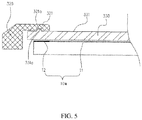
- a fourth embodiment is provided.
- the surface of the transparent protective plate 230 away from the display screen 210 corresponds to one surface of the transparent protective plate 230 close to the display screen 210.
- the frame flange 221 is laminated on the top surface 231.
- the viewable surface 2212 of the frame flange 221 and the top surface 231 form a step
- the shielding surface 2211 fits to the periphery of the top surface 231, and shields the non-display region 12 correspondingly.
- An orthographic projection region of the display surface 10a on the bottom surface 232 is smaller than the bottom surface 232.
- the protection area of the transparent protective plate 230 to the display screen 210 is larger, the appearance visual hierarchy effect of the display screen assembly 200 is stronger, the region division is more apparent, the transparent protective plate 230 can be well protected, and water and dust proof effect of the display screen assembly 100 (see FIG. 1 ) is better.
- a fifth embodiment is provided.
- the fifth embodiment is similar to the fourth embodiment, and a difference is that a depression 321a is provided on one side of the frame flange 321 close to the transparent protective plate 330.
- the transparent protective plate 330 is provided with a protrusion 331a corresponding to the depression 31a, and the protrusion 331a is received in the depression 321a.
- a plurality of depressions 321a are provided on the shielding surface 3211, and a plurality of protrusions 331a are provided on the periphery of the top surface 331 correspondingly.
- the depression 321a can be a rectangular groove, or can be a hemispherical groove, or can be further a tapered groove.
- the protrusion 331a is matched with the depression 321a.
- the protrusion 331a is received in the depression 321a, thus, on one hand, the structure of the transparent protective plate 330 and the frame 320 is more stable, and the structure performance of the display screen assembly 300 is improved; on the other hand, positioning of the transparent protective plate 330 to the frame 320 can be realized.
- the depression 321a can be provided on the sidewall 33 (see FIG. 1 ) of the transparent protective plate 330, and the protrusion 331a can be provided on the connection surface of the frame flange 321, thus the combination of the transparent protective plate 330 and the frame 320 can be realized.
- the present disclosure further provides a terminal (not illustrated).
- the terminal includes the display screen assembly 100.
- the terminal further includes a rear cover (not illustrated) and a control assembly (not illustrated).
- the rear cover is provided with a receiving cavity (not illustrated). An open end of the receiving cavity is located on the appearance surface of the rear cover.
- the display screen assembly 100 covers the open end.
- the display screen 10 and the control assembly are received in the receiving cavity.
- the control assembly is electrically coupled to the display screen 10 to control the display screen 10.
- the terminal can be a mobile phone, a laptop computer, a tablet computer, an electronic reader, an electronic album, a display, and so on.
- the inner side of the frame is provided with the frame flange, and the frame flange shields the non-display region correspondingly, thus the periphery of the inner side of the transparent protective plate does not need to be coated with an ink layer, that is, for the appearance of the display screen assembly, only the case frame and the display region of the display screen are viewable, visual hierarchies of the display screen assembly are reduced, and the frame of the display screen assembly does not include black ink edges, thus the visual effect of the display screen assembly is improved.
Applications Claiming Priority (2)
| Application Number | Priority Date | Filing Date | Title |
|---|---|---|---|
| CN201510189560.0A CN104866020A (zh) | 2015-04-20 | 2015-04-20 | 显示屏组件及终端 |
| PCT/CN2016/077549 WO2016169393A1 (fr) | 2015-04-20 | 2016-03-28 | Ensemble écran d'affichage et terminal |
Publications (3)
| Publication Number | Publication Date |
|---|---|
| EP3176671A1 true EP3176671A1 (fr) | 2017-06-07 |
| EP3176671A4 EP3176671A4 (fr) | 2018-03-28 |
| EP3176671B1 EP3176671B1 (fr) | 2019-12-18 |
Family
ID=53911914
Family Applications (1)
| Application Number | Title | Priority Date | Filing Date |
|---|---|---|---|
| EP16782541.3A Active EP3176671B1 (fr) | 2015-04-20 | 2016-03-28 | Ensemble écran d'affichage et terminal |
Country Status (5)
| Country | Link |
|---|---|
| US (1) | US10088871B2 (fr) |
| EP (1) | EP3176671B1 (fr) |
| CN (1) | CN104866020A (fr) |
| ES (1) | ES2766873T3 (fr) |
| WO (1) | WO2016169393A1 (fr) |
Cited By (1)
| Publication number | Priority date | Publication date | Assignee | Title |
|---|---|---|---|---|
| EP4137912A1 (fr) * | 2021-08-16 | 2023-02-22 | InnoLux Corporation | Dispositif d'affichage souple |
Families Citing this family (17)
| Publication number | Priority date | Publication date | Assignee | Title |
|---|---|---|---|---|
| CN104866020A (zh) | 2015-04-20 | 2015-08-26 | 广东欧珀移动通信有限公司 | 显示屏组件及终端 |
| CN105047082A (zh) * | 2015-08-28 | 2015-11-11 | 上海传英信息技术有限公司 | 一种显示设备的极窄边框结构 |
| CN105045347B (zh) * | 2015-08-31 | 2018-09-04 | 广东欧珀移动通信有限公司 | 终端前盖组件及移动终端 |
| US10015297B2 (en) * | 2015-09-08 | 2018-07-03 | Apple Inc. | Display cover retention features for a portable electronic device |
| CN205656556U (zh) * | 2016-05-25 | 2016-10-19 | 广东欧珀移动通信有限公司 | 一种移动终端 |
| EP3346355B1 (fr) * | 2017-01-09 | 2020-06-10 | Guangdong Oppo Mobile Telecommunications Corp., Ltd. | Ensemble écran d'affichage, son procédé d'assemblage et dispositif électronique |
| ES2729806T3 (es) | 2017-01-09 | 2019-11-06 | Guangdong Oppo Mobile Telecommunications Corp Ltd | Conjunto de pantalla de visualización, método de fabricación del mismo y dispositivo electrónico |
| CN106847091B (zh) * | 2017-01-09 | 2019-05-03 | Oppo广东移动通信有限公司 | 显示屏组件及其制造方法与电子装置 |
| US10412843B2 (en) | 2017-01-09 | 2019-09-10 | Guangdong Oppo Mobile Telecommunications Corp., Ltd. | Display panel assembly and manufacturing method thereof |
| CN107241468B (zh) * | 2017-05-12 | 2020-08-18 | Oppo广东移动通信有限公司 | 显示装置及移动终端 |
| CN107748461A (zh) | 2017-11-28 | 2018-03-02 | 广东欧珀移动通信有限公司 | 显示屏组件、移动终端及显示屏组件加工方法 |
| CN108108049A (zh) * | 2017-12-06 | 2018-06-01 | 北京小米移动软件有限公司 | 电子设备 |
| CN108733146B (zh) * | 2018-05-14 | 2021-01-15 | 维沃移动通信有限公司 | 移动终端 |
| JP7191579B2 (ja) * | 2018-08-01 | 2022-12-19 | キヤノン株式会社 | 表示装置および電子機器 |
| CN110827699B (zh) * | 2018-08-07 | 2021-02-23 | Oppo广东移动通信有限公司 | 屏幕、电子装置和屏幕的制造方法 |
| US11586242B2 (en) * | 2019-01-18 | 2023-02-21 | Samsung Display Co., Ltd. | Protection member for display device, display device including the same and method for fabricating protection member |
| CN110764651B (zh) * | 2019-10-25 | 2022-05-13 | 业成科技(成都)有限公司 | 显示装置 |
Family Cites Families (12)
| Publication number | Priority date | Publication date | Assignee | Title |
|---|---|---|---|---|
| JP4765837B2 (ja) * | 2006-08-23 | 2011-09-07 | ソニー株式会社 | バックライト装置及び液晶表示装置 |
| JP4445518B2 (ja) * | 2007-05-28 | 2010-04-07 | 株式会社 日立ディスプレイズ | 画像表示装置 |
| FR2923070B1 (fr) * | 2007-10-26 | 2010-07-30 | Archos | Ensemble boitier-ecran, son procede de fabrication, et appareil electronique portable ainsi equipe. |
| TWI356963B (en) * | 2007-12-18 | 2012-01-21 | Prime View Int Co Ltd | Electrophoretic display device |
| US20120113331A1 (en) * | 2009-07-30 | 2012-05-10 | Sharp Kabushiki Kaisha | Edge light type illuminating device, liquid crystal display device, television receiver, and method for manufacturing edge light type illuminating device |
| CN202495013U (zh) * | 2012-04-13 | 2012-10-17 | 广东欧珀移动通信有限公司 | 一种数码产品的触摸显示屏结构 |
| CN104736920B (zh) * | 2012-10-18 | 2017-06-13 | 夏普株式会社 | 照明装置的制造方法 |
| CN202835074U (zh) * | 2012-10-30 | 2013-03-27 | 京东方科技集团股份有限公司 | 一种背光源及显示装置 |
| JP2014138131A (ja) * | 2013-01-18 | 2014-07-28 | Takara Kasei Kogyo Kk | 筐体用ガラス板製カバー、筐体とガラス板との一体化成形方法、及びその構造 |
| CN103139340A (zh) * | 2013-03-04 | 2013-06-05 | 佳也瑞吉科技(深圳)有限公司 | 一种手机智能保护壳 |
| CN204066085U (zh) * | 2014-07-18 | 2014-12-31 | 深圳市星际移动通信设备有限公司 | 一种移动终端的窄边式前壳结构及移动终端 |
| CN104866020A (zh) * | 2015-04-20 | 2015-08-26 | 广东欧珀移动通信有限公司 | 显示屏组件及终端 |
-
2015
- 2015-04-20 CN CN201510189560.0A patent/CN104866020A/zh active Pending
-
2016
- 2016-03-28 ES ES16782541T patent/ES2766873T3/es active Active
- 2016-03-28 EP EP16782541.3A patent/EP3176671B1/fr active Active
- 2016-03-28 WO PCT/CN2016/077549 patent/WO2016169393A1/fr active Application Filing
-
2017
- 2017-03-07 US US15/452,316 patent/US10088871B2/en active Active
Cited By (3)
| Publication number | Priority date | Publication date | Assignee | Title |
|---|---|---|---|---|
| EP4137912A1 (fr) * | 2021-08-16 | 2023-02-22 | InnoLux Corporation | Dispositif d'affichage souple |
| TWI824462B (zh) * | 2021-08-16 | 2023-12-01 | 群創光電股份有限公司 | 可撓式顯示裝置 |
| US11963314B2 (en) | 2021-08-16 | 2024-04-16 | Innolux Corporation | Flexible display device |
Also Published As
| Publication number | Publication date |
|---|---|
| WO2016169393A1 (fr) | 2016-10-27 |
| CN104866020A (zh) | 2015-08-26 |
| US20170177032A1 (en) | 2017-06-22 |
| EP3176671B1 (fr) | 2019-12-18 |
| EP3176671A4 (fr) | 2018-03-28 |
| US10088871B2 (en) | 2018-10-02 |
| ES2766873T3 (es) | 2020-06-15 |
Similar Documents
| Publication | Publication Date | Title |
|---|---|---|
| EP3176671B1 (fr) | Ensemble écran d'affichage et terminal | |
| CN104933970B (zh) | 显示屏组件及终端 | |
| CN104866021B (zh) | 显示屏组件及终端 | |
| CN108254975B (zh) | 显示屏组件及电子设备 | |
| US10567563B2 (en) | Housing assembly, mobile terminal, and method for assembling housing assembly | |
| CN105120022B (zh) | 壳体组件及移动终端 | |
| US10698246B2 (en) | Display screen, display screen assembly, and terminal | |
| JP6895524B2 (ja) | ディスプレイ画面組立品、ディスプレイ画面組立品の組立て方法、および電子デバイス | |
| CN108259651B (zh) | 显示屏组件及电子设备 | |
| CN105208150B (zh) | 壳体组件及移动终端 | |
| CN104866018B (zh) | 终端前盖及终端 | |
| CN105263281B (zh) | 壳体组件及移动终端 | |
| EP3232257A1 (fr) | Dispositif d'affichage à côtés multiples | |
| CN110225159A (zh) | 显示装置、电子设备及显示装置制备方法 | |
| US20150016036A1 (en) | Translucent panel attachment structure and portable electronic device | |
| CN105045432A (zh) | 显示屏组件及终端 | |
| CN105430128A (zh) | 显示屏组件及移动终端 | |
| CN105120024A (zh) | 壳体组件及移动终端 | |
| CN204883473U (zh) | 显示屏组件及终端 | |
| JP2007065855A (ja) | タッチパネル付き表示装置 | |
| CN206060857U (zh) | 一种电子设备 | |
| CN111327733A (zh) | 一种电子设备 | |
| CN107835271B (zh) | 一种移动终端 | |
| CN105005413B (zh) | 显示屏模组及终端 | |
| CN105045343B (zh) | 一种电子设备 |
Legal Events
| Date | Code | Title | Description |
|---|---|---|---|
| STAA | Information on the status of an ep patent application or granted ep patent |
Free format text: STATUS: THE INTERNATIONAL PUBLICATION HAS BEEN MADE |
|
| 17P | Request for examination filed |
Effective date: 20170228 |
|
| AK | Designated contracting states |
Kind code of ref document: A1 Designated state(s): AL AT BE BG CH CY CZ DE DK EE ES FI FR GB GR HR HU IE IS IT LI LT LU LV MC MK MT NL NO PL PT RO RS SE SI SK SM TR |
|
| AX | Request for extension of the european patent |
Extension state: BA ME |
|
| PUAI | Public reference made under article 153(3) epc to a published international application that has entered the european phase |
Free format text: ORIGINAL CODE: 0009012 |
|
| STAA | Information on the status of an ep patent application or granted ep patent |
Free format text: STATUS: REQUEST FOR EXAMINATION WAS MADE |
|
| A4 | Supplementary search report drawn up and despatched |
Effective date: 20180227 |
|
| RIC1 | Information provided on ipc code assigned before grant |
Ipc: G06F 1/16 20060101AFI20180221BHEP |
|
| DAV | Request for validation of the european patent (deleted) | ||
| DAX | Request for extension of the european patent (deleted) | ||
| STAA | Information on the status of an ep patent application or granted ep patent |
Free format text: STATUS: EXAMINATION IS IN PROGRESS |
|
| 17Q | First examination report despatched |
Effective date: 20190220 |
|
| GRAP | Despatch of communication of intention to grant a patent |
Free format text: ORIGINAL CODE: EPIDOSNIGR1 |
|
| STAA | Information on the status of an ep patent application or granted ep patent |
Free format text: STATUS: GRANT OF PATENT IS INTENDED |
|
| INTG | Intention to grant announced |
Effective date: 20190925 |
|
| GRAS | Grant fee paid |
Free format text: ORIGINAL CODE: EPIDOSNIGR3 |
|
| GRAA | (expected) grant |
Free format text: ORIGINAL CODE: 0009210 |
|
| STAA | Information on the status of an ep patent application or granted ep patent |
Free format text: STATUS: THE PATENT HAS BEEN GRANTED |
|
| RAP1 | Party data changed (applicant data changed or rights of an application transferred) |
Owner name: GUANGDONG OPPO MOBILE TELECOMMUNICATIONS CORP., LT |
|
| AK | Designated contracting states |
Kind code of ref document: B1 Designated state(s): AL AT BE BG CH CY CZ DE DK EE ES FI FR GB GR HR HU IE IS IT LI LT LU LV MC MK MT NL NO PL PT RO RS SE SI SK SM TR |
|
| REG | Reference to a national code |
Ref country code: CH Ref legal event code: EP |
|
| REG | Reference to a national code |
Ref country code: DE Ref legal event code: R096 Ref document number: 602016026528 Country of ref document: DE |
|
| REG | Reference to a national code |
Ref country code: IE Ref legal event code: FG4D |
|
| REG | Reference to a national code |
Ref country code: AT Ref legal event code: REF Ref document number: 1215310 Country of ref document: AT Kind code of ref document: T Effective date: 20200115 |
|
| REG | Reference to a national code |
Ref country code: NL Ref legal event code: FP |
|
| PG25 | Lapsed in a contracting state [announced via postgrant information from national office to epo] |
Ref country code: LT Free format text: LAPSE BECAUSE OF FAILURE TO SUBMIT A TRANSLATION OF THE DESCRIPTION OR TO PAY THE FEE WITHIN THE PRESCRIBED TIME-LIMIT Effective date: 20191218 Ref country code: GR Free format text: LAPSE BECAUSE OF FAILURE TO SUBMIT A TRANSLATION OF THE DESCRIPTION OR TO PAY THE FEE WITHIN THE PRESCRIBED TIME-LIMIT Effective date: 20200319 Ref country code: BG Free format text: LAPSE BECAUSE OF FAILURE TO SUBMIT A TRANSLATION OF THE DESCRIPTION OR TO PAY THE FEE WITHIN THE PRESCRIBED TIME-LIMIT Effective date: 20200318 Ref country code: FI Free format text: LAPSE BECAUSE OF FAILURE TO SUBMIT A TRANSLATION OF THE DESCRIPTION OR TO PAY THE FEE WITHIN THE PRESCRIBED TIME-LIMIT Effective date: 20191218 Ref country code: SE Free format text: LAPSE BECAUSE OF FAILURE TO SUBMIT A TRANSLATION OF THE DESCRIPTION OR TO PAY THE FEE WITHIN THE PRESCRIBED TIME-LIMIT Effective date: 20191218 Ref country code: NO Free format text: LAPSE BECAUSE OF FAILURE TO SUBMIT A TRANSLATION OF THE DESCRIPTION OR TO PAY THE FEE WITHIN THE PRESCRIBED TIME-LIMIT Effective date: 20200318 Ref country code: LV Free format text: LAPSE BECAUSE OF FAILURE TO SUBMIT A TRANSLATION OF THE DESCRIPTION OR TO PAY THE FEE WITHIN THE PRESCRIBED TIME-LIMIT Effective date: 20191218 |
|
| REG | Reference to a national code |
Ref country code: LT Ref legal event code: MG4D |
|
| PG25 | Lapsed in a contracting state [announced via postgrant information from national office to epo] |
Ref country code: HR Free format text: LAPSE BECAUSE OF FAILURE TO SUBMIT A TRANSLATION OF THE DESCRIPTION OR TO PAY THE FEE WITHIN THE PRESCRIBED TIME-LIMIT Effective date: 20191218 Ref country code: RS Free format text: LAPSE BECAUSE OF FAILURE TO SUBMIT A TRANSLATION OF THE DESCRIPTION OR TO PAY THE FEE WITHIN THE PRESCRIBED TIME-LIMIT Effective date: 20191218 |
|
| REG | Reference to a national code |
Ref country code: ES Ref legal event code: FG2A Ref document number: 2766873 Country of ref document: ES Kind code of ref document: T3 Effective date: 20200615 |
|
| PG25 | Lapsed in a contracting state [announced via postgrant information from national office to epo] |
Ref country code: AL Free format text: LAPSE BECAUSE OF FAILURE TO SUBMIT A TRANSLATION OF THE DESCRIPTION OR TO PAY THE FEE WITHIN THE PRESCRIBED TIME-LIMIT Effective date: 20191218 |
|
| PG25 | Lapsed in a contracting state [announced via postgrant information from national office to epo] |
Ref country code: CZ Free format text: LAPSE BECAUSE OF FAILURE TO SUBMIT A TRANSLATION OF THE DESCRIPTION OR TO PAY THE FEE WITHIN THE PRESCRIBED TIME-LIMIT Effective date: 20191218 Ref country code: PT Free format text: LAPSE BECAUSE OF FAILURE TO SUBMIT A TRANSLATION OF THE DESCRIPTION OR TO PAY THE FEE WITHIN THE PRESCRIBED TIME-LIMIT Effective date: 20200513 Ref country code: RO Free format text: LAPSE BECAUSE OF FAILURE TO SUBMIT A TRANSLATION OF THE DESCRIPTION OR TO PAY THE FEE WITHIN THE PRESCRIBED TIME-LIMIT Effective date: 20191218 Ref country code: EE Free format text: LAPSE BECAUSE OF FAILURE TO SUBMIT A TRANSLATION OF THE DESCRIPTION OR TO PAY THE FEE WITHIN THE PRESCRIBED TIME-LIMIT Effective date: 20191218 |
|
| PG25 | Lapsed in a contracting state [announced via postgrant information from national office to epo] |
Ref country code: SK Free format text: LAPSE BECAUSE OF FAILURE TO SUBMIT A TRANSLATION OF THE DESCRIPTION OR TO PAY THE FEE WITHIN THE PRESCRIBED TIME-LIMIT Effective date: 20191218 Ref country code: IS Free format text: LAPSE BECAUSE OF FAILURE TO SUBMIT A TRANSLATION OF THE DESCRIPTION OR TO PAY THE FEE WITHIN THE PRESCRIBED TIME-LIMIT Effective date: 20200418 Ref country code: SM Free format text: LAPSE BECAUSE OF FAILURE TO SUBMIT A TRANSLATION OF THE DESCRIPTION OR TO PAY THE FEE WITHIN THE PRESCRIBED TIME-LIMIT Effective date: 20191218 |
|
| REG | Reference to a national code |
Ref country code: DE Ref legal event code: R097 Ref document number: 602016026528 Country of ref document: DE |
|
| REG | Reference to a national code |
Ref country code: AT Ref legal event code: MK05 Ref document number: 1215310 Country of ref document: AT Kind code of ref document: T Effective date: 20191218 |
|
| PLBE | No opposition filed within time limit |
Free format text: ORIGINAL CODE: 0009261 |
|
| STAA | Information on the status of an ep patent application or granted ep patent |
Free format text: STATUS: NO OPPOSITION FILED WITHIN TIME LIMIT |
|
| PG25 | Lapsed in a contracting state [announced via postgrant information from national office to epo] |
Ref country code: DK Free format text: LAPSE BECAUSE OF FAILURE TO SUBMIT A TRANSLATION OF THE DESCRIPTION OR TO PAY THE FEE WITHIN THE PRESCRIBED TIME-LIMIT Effective date: 20191218 Ref country code: MC Free format text: LAPSE BECAUSE OF FAILURE TO SUBMIT A TRANSLATION OF THE DESCRIPTION OR TO PAY THE FEE WITHIN THE PRESCRIBED TIME-LIMIT Effective date: 20191218 |
|
| REG | Reference to a national code |
Ref country code: CH Ref legal event code: PL |
|
| 26N | No opposition filed |
Effective date: 20200921 |
|
| PG25 | Lapsed in a contracting state [announced via postgrant information from national office to epo] |
Ref country code: AT Free format text: LAPSE BECAUSE OF FAILURE TO SUBMIT A TRANSLATION OF THE DESCRIPTION OR TO PAY THE FEE WITHIN THE PRESCRIBED TIME-LIMIT Effective date: 20191218 Ref country code: SI Free format text: LAPSE BECAUSE OF FAILURE TO SUBMIT A TRANSLATION OF THE DESCRIPTION OR TO PAY THE FEE WITHIN THE PRESCRIBED TIME-LIMIT Effective date: 20191218 |
|
| REG | Reference to a national code |
Ref country code: BE Ref legal event code: MM Effective date: 20200331 |
|
| PG25 | Lapsed in a contracting state [announced via postgrant information from national office to epo] |
Ref country code: LU Free format text: LAPSE BECAUSE OF NON-PAYMENT OF DUE FEES Effective date: 20200328 |
|
| PG25 | Lapsed in a contracting state [announced via postgrant information from national office to epo] |
Ref country code: IE Free format text: LAPSE BECAUSE OF NON-PAYMENT OF DUE FEES Effective date: 20200328 Ref country code: LI Free format text: LAPSE BECAUSE OF NON-PAYMENT OF DUE FEES Effective date: 20200331 Ref country code: CH Free format text: LAPSE BECAUSE OF NON-PAYMENT OF DUE FEES Effective date: 20200331 |
|
| PG25 | Lapsed in a contracting state [announced via postgrant information from national office to epo] |
Ref country code: BE Free format text: LAPSE BECAUSE OF NON-PAYMENT OF DUE FEES Effective date: 20200331 Ref country code: PL Free format text: LAPSE BECAUSE OF FAILURE TO SUBMIT A TRANSLATION OF THE DESCRIPTION OR TO PAY THE FEE WITHIN THE PRESCRIBED TIME-LIMIT Effective date: 20191218 |
|
| PG25 | Lapsed in a contracting state [announced via postgrant information from national office to epo] |
Ref country code: TR Free format text: LAPSE BECAUSE OF FAILURE TO SUBMIT A TRANSLATION OF THE DESCRIPTION OR TO PAY THE FEE WITHIN THE PRESCRIBED TIME-LIMIT Effective date: 20191218 Ref country code: MT Free format text: LAPSE BECAUSE OF FAILURE TO SUBMIT A TRANSLATION OF THE DESCRIPTION OR TO PAY THE FEE WITHIN THE PRESCRIBED TIME-LIMIT Effective date: 20191218 Ref country code: CY Free format text: LAPSE BECAUSE OF FAILURE TO SUBMIT A TRANSLATION OF THE DESCRIPTION OR TO PAY THE FEE WITHIN THE PRESCRIBED TIME-LIMIT Effective date: 20191218 |
|
| PG25 | Lapsed in a contracting state [announced via postgrant information from national office to epo] |
Ref country code: MK Free format text: LAPSE BECAUSE OF FAILURE TO SUBMIT A TRANSLATION OF THE DESCRIPTION OR TO PAY THE FEE WITHIN THE PRESCRIBED TIME-LIMIT Effective date: 20191218 |
|
| PGFP | Annual fee paid to national office [announced via postgrant information from national office to epo] |
Ref country code: NL Payment date: 20221227 Year of fee payment: 8 Ref country code: FR Payment date: 20221223 Year of fee payment: 8 |
|
| PGFP | Annual fee paid to national office [announced via postgrant information from national office to epo] |
Ref country code: IT Payment date: 20221227 Year of fee payment: 8 Ref country code: GB Payment date: 20230321 Year of fee payment: 8 Ref country code: DE Payment date: 20221222 Year of fee payment: 8 |
|
| P01 | Opt-out of the competence of the unified patent court (upc) registered |
Effective date: 20230412 |
|
| PGFP | Annual fee paid to national office [announced via postgrant information from national office to epo] |
Ref country code: ES Payment date: 20230414 Year of fee payment: 8 |