EP3176594A2 - Stromzähler mit verbessertem messkreis - Google Patents
Stromzähler mit verbessertem messkreis Download PDFInfo
- Publication number
- EP3176594A2 EP3176594A2 EP16198010.7A EP16198010A EP3176594A2 EP 3176594 A2 EP3176594 A2 EP 3176594A2 EP 16198010 A EP16198010 A EP 16198010A EP 3176594 A2 EP3176594 A2 EP 3176594A2
- Authority
- EP
- European Patent Office
- Prior art keywords
- energy processing
- electricity meter
- resistance element
- shunt
- resistor
- Prior art date
- Legal status (The legal status is an assumption and is not a legal conclusion. Google has not performed a legal analysis and makes no representation as to the accuracy of the status listed.)
- Withdrawn
Links
Images

Classifications
-
- G—PHYSICS
- G01—MEASURING; TESTING
- G01R—MEASURING ELECTRIC VARIABLES; MEASURING MAGNETIC VARIABLES
- G01R1/00—Details of instruments or arrangements of the types included in groups G01R5/00 - G01R13/00 and G01R31/00
- G01R1/20—Modifications of basic electric elements for use in electric measuring instruments; Structural combinations of such elements with such instruments
- G01R1/203—Resistors used for electric measuring, e.g. decade resistors standards, resistors for comparators, series resistors, shunts
-
- G—PHYSICS
- G01—MEASURING; TESTING
- G01R—MEASURING ELECTRIC VARIABLES; MEASURING MAGNETIC VARIABLES
- G01R22/00—Arrangements for measuring time integral of electric power or current, e.g. electricity meters
- G01R22/06—Arrangements for measuring time integral of electric power or current, e.g. electricity meters by electronic methods
- G01R22/061—Details of electronic electricity meters
- G01R22/068—Arrangements for indicating or signaling faults
-
- G—PHYSICS
- G01—MEASURING; TESTING
- G01R—MEASURING ELECTRIC VARIABLES; MEASURING MAGNETIC VARIABLES
- G01R31/00—Arrangements for testing electric properties; Arrangements for locating electric faults; Arrangements for electrical testing characterised by what is being tested not provided for elsewhere
- G01R31/50—Testing of electric apparatus, lines, cables or components for short-circuits, continuity, leakage current or incorrect line connections
- G01R31/52—Testing for short-circuits, leakage current or ground faults
-
- G—PHYSICS
- G01—MEASURING; TESTING
- G01R—MEASURING ELECTRIC VARIABLES; MEASURING MAGNETIC VARIABLES
- G01R35/00—Testing or calibrating of apparatus covered by the other groups of this subclass
- G01R35/04—Testing or calibrating of apparatus covered by the other groups of this subclass of instruments for measuring time integral of power or current
Definitions
- the present invention relates to an electricity meter for measuring electricity consumption supplied to a consumption site, and for detecting earth fault conditions.
- the invention further relates to a shunt-resistor for such an electricity meter and to a method for the manufacture of such a shunt-resistor.
- Electricity meters are widely used for measuring electricity consumption for invoicing purposes also referred to as metering. In addition to invoicing purposes, measurements may also be used for other purposes related to system monitoring, demand monitoring and failure mode detection.
- Ground faults or earth faults are one type of faults that may cause potentially life threatening situations wherein currents of significant magnitude leak from an electrical circuit and run into the ground. Earth current or residual current running through the ground may be dangerous to both humans and animals and are caused by system failures, such as a defective electrical devices.
- An object of the present invention is to provide an electricity meter that provides an alternative to the prior art and an electricity meter with an improved measurement circuit.
- an electricity meter for measuring electricity consumption supplied to a consumption site
- the electricity meter having a measuring circuit for measuring the electricity consumption supplied via one or more live and/or neutral conductors and for detecting earth fault conditions, comprising: a shunt-resistor arranged in line with each of the live and/or neutral conductors connected with the electricity meter; an energy processing system for simultaneously determining the current passing through each of the live and neutral conductors based on a potential difference measured across the respective shunt-resistors, the energy processing system being adapted to detect the presence, magnitude and time of occurrence of a leak current at the consumption site, by summation of the determined currents running simultaneously in the live and/or neutral conductors; a memory module adapted to receive and store data indicative of earth fault from the energy processing system; and a communication module adapted to provide communication between the electricity meter and a utility server, the communication module being adapted to receive data indicative of
- the invention further relates to a shunt-resistor for a measuring circuit of an electricity meter adapted to detect earth fault conditions, comprising: two contact elements providing an input terminal and an output terminal, respectively; and a resistance element extending in a longitudinal direction between the two contact elements, the resistance element having a contact surface and being provided with at least two measuring terminals; wherein the contact elements are secured to the contact surface of the resistance element at opposite contact points and that a groove is milled in the contact surface of the resistance element in a transversal direction between the contacts points.
- the groove of the above-mentioned shunt-resistor may at least partially overlap the measuring terminals.
- the measuring terminals may be formed as an integral part of the resistance element extending in the transversal direction.
- the contact elements may be secured to the contact surface of the resistance element by welding or soldering.
- each of the measuring terminals of the, when seen in a direction towards the contact surface of the resistance element may comprise a straight base section proximal the resistance element and a distal head section being wider than the base section and the groove may extend onto at least the base section of the measuring terminals.
- the invention relates to a method for the manufacture of a shunt-resistor as described above, comprising the steps of: welding or soldering contact elements onto a resistance element to provide a shunt-resistor, fixating the shunt resistor in an fixation device that centers the resistance element, removing material from both the resistance element and the contact elements by milling, along a transversal center line of the resistance element, a groove in the shunt resistor.
- the above described electricity meter, shunt-resistor and method for the manufacture of the same is particularly, but not exclusively, advantageous for obtaining an improved measurement circuit for determining residual currents.
- the distal end of the contact elements are precisely positioned in relation to the measuring terminals.
- a shut resistor with a high relative accuracy is achieved.
- a shut-resistor having an improved balance between signal strength measurable at the measuring terminals and effect loss across the shut-resistor is achieved.
- the electricity meter comprises a measuring circuit for measuring the electricity consumption supplied via three live conductors (P1, P2, P3) and a neutral conductor (N).
- P1, P2, P3 live conductors
- N neutral conductor
- the electricity meter may also be adapted to measure electricity consumption supplied via fewer conductors and without a neutral conductor.
- the electricity meter may for example be connected with only two or three live conductors without the presence of a neutral conductor.
- the shown measuring circuit comprises shunt-resistors 1a, 1b, 1c, 1d arranged in series with each of the live conductors and the neutral conductor.
- the shunt-resistors are connected with energy processing units (EPUs) 202a, 202b, 202c adapted to sample the current running through each of the conductors based on a voltage difference measured across the shunt-resistors.
- the EPUs are further adapted to measure the voltage in each of the conductors, and based on these current and voltage determinations, determine the energy supplied through each of the conductors.
- the EPUs are connected to a supplementary energy processing unit (SEPU) 201 via galvanic isolators 23a, 23b, 23c. Data regarding voltage and current measurements, and calculated energy supply is transferred from the EPUs 202a, 202b, 202c to a supplementary energy processing unit (SEPU) 201 via the galvanic isolators. Similar, electronic signals, such as a clock signal, may be transmitted form the SEPU to the EPUs via the galvanic isolators, as will be further described below.
- SEPU supplementary energy processing unit
- Voltage- and current measurement data in the neutral conductor is transferred from the energy processing unit 202d to the SEPU 201.
- the shunt 1d and the EPU 202d arranged in connection with the neutral conductor are omitted.
- the SEPU current measurements related to the live and neutral conductors are summarized to determine whether current is leaking from the electrical circuit at the load side of the electricity meter.
- the SEPU also ensures that sampling performed at the EPUs is synchronized, i.e. that currents determination at the different EPUs based on the shunt-resistor measurements are performed at the same points in time. If the sampling performed at the different EPUs is not sufficiently synchronized, data from each of the EPUs cannot be compared to determine for example current leaks.
- the EPUs 202a, 202b, 202c, 202d and the SEPU 201 together, provide the necessary processing of data to determine amongst others current leaks resulting from system defects at the load side. Consequently, the EPUs and the SEPU thus together constitute an energy processing system 20 of the electricity meter adapted to determining the current passing through each of the live and neutral conductors and to detect the presence, magnitude and time of occurrence of a leak current at the consumption site.
- the SEPU 201 is configured to transmit a dedicated clock signal to each of the EPUs.
- clock signals distributed by a common processing unit, i.e. the SEPU to each of the EPUs, it is possible to synchronize the sample process at each of the EPUs.
- the sampling rates of the EPUs 202a, 202b, 202c, 202d are controlled by the SEPU.
- the clock signal from the SEPU has a clock rate frequency of 4,1 MHz.
- clock signal having clock rates of both higher and lower frequencies may be applied.
- Each EPU initiates sampling based on the received clock signal and returns sample data to the SEPU. Based on the time of reception of the sample data from each of the EPUs, the SEPU determines whether sampling performed by each EPU is sufficiently synchronized with the sampling of the other EPUs.
- each EPU may transmit a separate synchronization signal to the SEPU and based on the synchronization signal the SEPU then determines whether sampling performed by each EPU is sufficiently synchronized.
- the clock signal sent to that particular EPU is modified to change the sampling time.
- the clock signal is modified by reducing the frequency of the clock signal to about half the original frequency for a predetermined period of time.
- the original frequency of 4,1 MHz is reduced to 2,05 MHz for 400-500 nanoseconds (ns). It is envisaged by the skilled person that other frequencies and time intervals may be applied to achieve a similar purpose.
- the sampling time at the respective EPU is delayed until it is sufficiently synchronized with the sampling time of the other EPUs. Synchronization of the sampling time may be achieved through several iterations of modification of the sampling signal. Following one period of modification of the clock signal the SEPU may determine whether the respective EPU is still not sufficiently synchronized. If this is the case the clock signal may be modified again to further synchronize the sampling time of the EPU .
- This synchronization of the EPU sampling process may take place both during start-up of the electricity meter and continuously during operation of the electricity meter.
- the electricity meter further comprises a control unit 21 controlling the overall operation of the electricity meter, a memory module 25 for storing measurements and calculated values, and a communication module 24 for g communicating via a communication network.
- the current leakage information may be transmitted by the communication module 24 via a wireless- or wired connection to a central utility server 26 arranged at a remote location, e.g. at the premises of a utility company.
- the current leakage information may be transmitted as an alarm that is picked up at the utility company by a surveillance system, and based on the characteristics of the alarm, different action may be initiated. For example, further system diagnostics may be performed to determine the extent and severity of the detected earth fault.
- the current leak information may also be used as a basis for disconnecting the power supply to the consumption site, for example as input to a Residual-current device (RCD).
- RCD Residual-current device
- the communication module 24 is a 2-way communication module adapted to transmit and receive data packets via a communication network.
- the electricity meter may receive data packets, such as commands to be executed, from the utility server. Such commands may instruct the electricity meter to interrupt the supply of power to the consumption site.
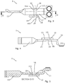
- Figures 2 to 5 show a shunt-resistor 1 comprising two contact elements 11 extending from a resistance element 12 in a longitudinal direction.
- the contact elements are of a cobber material having a low resistance and excellent current conducting characteristics.
- the contact elements are adapted for being connected to the supply side and load side of the conductors connected to the electricity meter 1.
- the contact elements are secured to opposite ends of a resistance element 12 extending in the longitudinal direction.
- the contact elements are secured to a contact surface 13 of the resistance element 12 by welding using a filler material.
- the contact elements may also be secured to the resistance element by welding without using a filler material or by soldering.
- the resistance element 12 is provided with two measuring terminals 14 extending in a transversal direction from one side of the resistance element itself.
- the measurement terminals are adapted to be connected to the measurement wires of a measurement circuit.
- the measuring terminals are in electrical communication with the EPUs 202a, 202b, 202c, 202d, and the current in the shunt-resistors is thus sampled, i.e. measured, across these terminals.
- the measuring terminals are made as an integrated part of the resistance element and the resistance element and measuring terminals may thus be of a monolithic construction.
- Each of the measuring terminals comprises a straight base section 17 proximal the resistance element and a distal head section 18.
- the distal head section is wider than the base section and provides a connection surface for the mounting of measurement wires (not shown) to the measuring terminals.
- the resistance element and the measuring terminals are of a managing material having a known resistance and a temperature coefficient.
- a milled groove 16 is provided in the contact surface of the resistance element in a transversal direction between the contacts points of the contact elements.
- the groove is centered about a transversal center line 161 of the resistance element and thus removes resistance element material between the contact elements.
- the milled groove extends onto the base sections of the measuring terminals.
- any material of the contact elements, such as cobber, or any material resulting from the joining of the resistance element and contact elements, such as weld pool are removed from identical parts of each of the base sections of the measuring terminals.
- a groove of a certain dept is provided in the surface of the resistor element.
- the depth of the groove in the shown embodiment corresponds to approximately 15 percent (15%) of the maximum thickness of the resistance element.
- the groove may be of zero depth in relation to the original surface of the resistance element so that only contact element material and/or material resulting from the joining of the contact elements and resistance element are removed when the groove is milled.
- the milled groove thus accurately controls the position of the contact elements in relation to the measurement terminals.
- the precise positioning of the contact elements is essential to the accuracy of the shunt-resistor as variations in the position of the contact elements in relation to the resistance element influence the accuracy of the current measurements across the resistance element.
- the contact elements have a lower resistance that the resistance element, electrodes tend to run through the contact elements as far as possible.
- the electrons thus tend to leave the contact elements and run through the resistance element.
- the electron concentration thus becomes higher at the transition points 19 and the position of the transition points becomes a determining factor for the accuracy of the shunt-resistor.
- the shunt-resistor renders possible a less demanding manufacturing process.
- the shunt-resistor may be manufactured by a method wherein the resistor element and the contact elements are assembled by welding or soldering, fixating the contact elements onto the resistance element. Subsequently, the resulting shunt-resistor assembly is fixated in a fixation device that centers the resistance element.
- a groove may be milled along a transversal center line 161 of the resistance element. By milling the groove material may be removed from both the resistance element and/or the contact elements. A described previously, the milling of the groove ensures a proper alignment and positioning of the contact element in relation to the measuring terminals of the resistor elements.
Landscapes
- Physics & Mathematics (AREA)
- General Physics & Mathematics (AREA)
- Engineering & Computer Science (AREA)
- Power Engineering (AREA)
- Measurement Of Current Or Voltage (AREA)
Applications Claiming Priority (1)
| Application Number | Priority Date | Filing Date | Title |
|---|---|---|---|
| EP15193779 | 2015-11-10 |
Publications (2)
| Publication Number | Publication Date |
|---|---|
| EP3176594A2 true EP3176594A2 (de) | 2017-06-07 |
| EP3176594A3 EP3176594A3 (de) | 2017-08-16 |
Family
ID=54539897
Family Applications (1)
| Application Number | Title | Priority Date | Filing Date |
|---|---|---|---|
| EP16198010.7A Withdrawn EP3176594A3 (de) | 2015-11-10 | 2016-11-09 | Stromzähler mit verbessertem messkreis |
Country Status (1)
| Country | Link |
|---|---|
| EP (1) | EP3176594A3 (de) |
Family Cites Families (7)
| Publication number | Priority date | Publication date | Assignee | Title |
|---|---|---|---|---|
| US5995911A (en) * | 1997-02-12 | 1999-11-30 | Power Measurement Ltd. | Digital sensor apparatus and system for protection, control, and management of electricity distribution systems |
| GB0000067D0 (en) * | 2000-01-06 | 2000-02-23 | Delta Electrical Limited | Current detector and current measurement apparatus including such detector with temparature compensation |
| US6947854B2 (en) * | 2000-02-29 | 2005-09-20 | Quadlogic Controls Corporation | System and method for on-line monitoring and billing of power consumption |
| GB2376360B (en) * | 2001-06-08 | 2005-08-24 | Delta Electrical Ltd | Measuring device |
| CN1602507A (zh) * | 2001-09-14 | 2005-03-30 | 兰迪斯+盖尔公司 | 具有由外部信号供电的收发信机的公用表 |
| US20070067119A1 (en) * | 2005-09-16 | 2007-03-22 | Power Measurement Ltd. | Rack-mounted power meter having removable metering options module |
| US9267972B2 (en) * | 2013-02-14 | 2016-02-23 | Infineon Technologies Austria Ag | Integrated galvanically isolated meter devices and methods for making integrated galvanically isolated meter devices |
-
2016
- 2016-11-09 EP EP16198010.7A patent/EP3176594A3/de not_active Withdrawn
Non-Patent Citations (1)
| Title |
|---|
| None |
Also Published As
| Publication number | Publication date |
|---|---|
| EP3176594A3 (de) | 2017-08-16 |
Similar Documents
| Publication | Publication Date | Title |
|---|---|---|
| US9239352B2 (en) | Method of measuring earth ground resistance of a pylon | |
| CN103081292B (zh) | 具有集成的串电流监控的太阳能组合器 | |
| US20150088438A1 (en) | Ratio metric current measurement | |
| KR101731705B1 (ko) | 계기용 변류기 회로 검사 장치 및 방법 | |
| KR101571946B1 (ko) | 소비 전력 관리 시스템 | |
| CN103675705A (zh) | 一种动力电池的电流冗余校验方法 | |
| CN113281618B (zh) | 一种低压配电线路故障定位方法及装置 | |
| KR102004337B1 (ko) | 사물인터넷(IoT) 기반의 전기안전 감시 장치 및 그 제어 방법 | |
| US20140152329A1 (en) | Insulation Monitoring Device With Measuring Circuit Interruption | |
| US9753063B2 (en) | Load side voltage sensing for utility meter | |
| JP7429339B2 (ja) | 非同期測定を使用した、パラメータに依存しない進行波ベースの故障位置特定 | |
| CN104749542B (zh) | 检测系统的校正与运作方法 | |
| JP6932964B2 (ja) | 直流電源供給回路の断線判別装置及び配線判別装置 | |
| EP3176594A2 (de) | Stromzähler mit verbessertem messkreis | |
| EP2811305A1 (de) | Sammelschienen-Strommessanordnung | |
| KR101529476B1 (ko) | 태양광 모듈 스트링의 절연저항 감시 시스템 | |
| CN103017939A (zh) | 新型温度控制器校验装置 | |
| US20040130327A1 (en) | Ground circuit impedance measurement apparatus and method | |
| KR101748340B1 (ko) | 열배관의 절연저항 측정 방법 및 시스템 | |
| KR20090132349A (ko) | 씨티 극성 판별장치 | |
| CN107102235B (zh) | 一种gis母线接头的电接触状态判别方法和装置 | |
| KR200435296Y1 (ko) | 바이메탈이 내장된 단자대 및 이를 이용한 전기화재 감시용 단자대 | |
| TW201523011A (zh) | 檢測系統的校正與除錯方法 | |
| KR101687330B1 (ko) | 열배관의 절연저항 측정 방법 및 시스템 | |
| CN111060759A (zh) | 一种配电柜测试系统及测试方法 |
Legal Events
| Date | Code | Title | Description |
|---|---|---|---|
| AK | Designated contracting states |
Kind code of ref document: A2 Designated state(s): AL AT BE BG CH CY CZ DE DK EE ES FI FR GB GR HR HU IE IS IT LI LT LU LV MC MK MT NL NO PL PT RO RS SE SI SK SM TR |
|
| AX | Request for extension of the european patent |
Extension state: BA ME |
|
| PUAI | Public reference made under article 153(3) epc to a published international application that has entered the european phase |
Free format text: ORIGINAL CODE: 0009012 |
|
| PUAL | Search report despatched |
Free format text: ORIGINAL CODE: 0009013 |
|
| AK | Designated contracting states |
Kind code of ref document: A3 Designated state(s): AL AT BE BG CH CY CZ DE DK EE ES FI FR GB GR HR HU IE IS IT LI LT LU LV MC MK MT NL NO PL PT RO RS SE SI SK SM TR |
|
| AX | Request for extension of the european patent |
Extension state: BA ME |
|
| RIC1 | Information provided on ipc code assigned before grant |
Ipc: G01R 21/133 20060101AFI20170707BHEP Ipc: G01R 1/20 20060101ALI20170707BHEP Ipc: G01R 35/04 20060101ALN20170707BHEP Ipc: G01R 31/02 20060101ALN20170707BHEP |
|
| STAA | Information on the status of an ep patent application or granted ep patent |
Free format text: STATUS: THE APPLICATION IS DEEMED TO BE WITHDRAWN |
|
| 18D | Application deemed to be withdrawn |
Effective date: 20180217 |