EP3176537A1 - System for automated in-process inspection of welds - Google Patents
System for automated in-process inspection of welds Download PDFInfo
- Publication number
- EP3176537A1 EP3176537A1 EP16201012.8A EP16201012A EP3176537A1 EP 3176537 A1 EP3176537 A1 EP 3176537A1 EP 16201012 A EP16201012 A EP 16201012A EP 3176537 A1 EP3176537 A1 EP 3176537A1
- Authority
- EP
- European Patent Office
- Prior art keywords
- weld
- images
- production
- camera
- defects
- Prior art date
- Legal status (The legal status is an assumption and is not a legal conclusion. Google has not performed a legal analysis and makes no representation as to the accuracy of the status listed.)
- Granted
Links
Images


Classifications
-
- G—PHYSICS
- G01—MEASURING; TESTING
- G01N—INVESTIGATING OR ANALYSING MATERIALS BY DETERMINING THEIR CHEMICAL OR PHYSICAL PROPERTIES
- G01N21/00—Investigating or analysing materials by the use of optical means, i.e. using sub-millimetre waves, infrared, visible or ultraviolet light
- G01N21/84—Systems specially adapted for particular applications
- G01N21/88—Investigating the presence of flaws or contamination
- G01N21/8851—Scan or image signal processing specially adapted therefor, e.g. for scan signal adjustment, for detecting different kinds of defects, for compensating for structures, markings, edges
-
- B—PERFORMING OPERATIONS; TRANSPORTING
- B23—MACHINE TOOLS; METAL-WORKING NOT OTHERWISE PROVIDED FOR
- B23K—SOLDERING OR UNSOLDERING; WELDING; CLADDING OR PLATING BY SOLDERING OR WELDING; CUTTING BY APPLYING HEAT LOCALLY, e.g. FLAME CUTTING; WORKING BY LASER BEAM
- B23K31/00—Processes relevant to this subclass, specially adapted for particular articles or purposes, but not covered by any single one of main groups B23K1/00 - B23K28/00
- B23K31/12—Processes relevant to this subclass, specially adapted for particular articles or purposes, but not covered by any single one of main groups B23K1/00 - B23K28/00 relating to investigating the properties, e.g. the weldability, of materials
- B23K31/125—Weld quality monitoring
-
- B—PERFORMING OPERATIONS; TRANSPORTING
- B23—MACHINE TOOLS; METAL-WORKING NOT OTHERWISE PROVIDED FOR
- B23K—SOLDERING OR UNSOLDERING; WELDING; CLADDING OR PLATING BY SOLDERING OR WELDING; CUTTING BY APPLYING HEAT LOCALLY, e.g. FLAME CUTTING; WORKING BY LASER BEAM
- B23K9/00—Arc welding or cutting
- B23K9/02—Seam welding; Backing means; Inserts
- B23K9/028—Seam welding; Backing means; Inserts for curved planar seams
-
- B—PERFORMING OPERATIONS; TRANSPORTING
- B23—MACHINE TOOLS; METAL-WORKING NOT OTHERWISE PROVIDED FOR
- B23K—SOLDERING OR UNSOLDERING; WELDING; CLADDING OR PLATING BY SOLDERING OR WELDING; CUTTING BY APPLYING HEAT LOCALLY, e.g. FLAME CUTTING; WORKING BY LASER BEAM
- B23K9/00—Arc welding or cutting
- B23K9/095—Monitoring or automatic control of welding parameters
- B23K9/0956—Monitoring or automatic control of welding parameters using sensing means, e.g. optical
-
- B—PERFORMING OPERATIONS; TRANSPORTING
- B23—MACHINE TOOLS; METAL-WORKING NOT OTHERWISE PROVIDED FOR
- B23K—SOLDERING OR UNSOLDERING; WELDING; CLADDING OR PLATING BY SOLDERING OR WELDING; CUTTING BY APPLYING HEAT LOCALLY, e.g. FLAME CUTTING; WORKING BY LASER BEAM
- B23K9/00—Arc welding or cutting
- B23K9/16—Arc welding or cutting making use of shielding gas
- B23K9/167—Arc welding or cutting making use of shielding gas and of a non-consumable electrode
-
- B—PERFORMING OPERATIONS; TRANSPORTING
- B25—HAND TOOLS; PORTABLE POWER-DRIVEN TOOLS; MANIPULATORS
- B25J—MANIPULATORS; CHAMBERS PROVIDED WITH MANIPULATION DEVICES
- B25J19/00—Accessories fitted to manipulators, e.g. for monitoring, for viewing; Safety devices combined with or specially adapted for use in connection with manipulators
- B25J19/02—Sensing devices
- B25J19/021—Optical sensing devices
-
- B—PERFORMING OPERATIONS; TRANSPORTING
- B25—HAND TOOLS; PORTABLE POWER-DRIVEN TOOLS; MANIPULATORS
- B25J—MANIPULATORS; CHAMBERS PROVIDED WITH MANIPULATION DEVICES
- B25J9/00—Program-controlled manipulators
- B25J9/16—Program controls
- B25J9/1628—Program controls characterised by the control loop
- B25J9/163—Program controls characterised by the control loop learning, adaptive, model based, rule based expert control
-
- F—MECHANICAL ENGINEERING; LIGHTING; HEATING; WEAPONS; BLASTING
- F01—MACHINES OR ENGINES IN GENERAL; ENGINE PLANTS IN GENERAL; STEAM ENGINES
- F01D—NON-POSITIVE DISPLACEMENT MACHINES OR ENGINES, e.g. STEAM TURBINES
- F01D5/00—Blades; Blade-carrying members; Heating, heat-insulating, cooling or antivibration means on the blades or the members
- F01D5/02—Blade-carrying members, e.g. rotors
-
- G—PHYSICS
- G01—MEASURING; TESTING
- G01B—MEASURING LENGTH, THICKNESS OR SIMILAR LINEAR DIMENSIONS; MEASURING ANGLES; MEASURING AREAS; MEASURING IRREGULARITIES OF SURFACES OR CONTOURS
- G01B11/00—Measuring arrangements characterised by the use of optical techniques
- G01B11/24—Measuring arrangements characterised by the use of optical techniques for measuring contours or curvatures
-
- G—PHYSICS
- G01—MEASURING; TESTING
- G01B—MEASURING LENGTH, THICKNESS OR SIMILAR LINEAR DIMENSIONS; MEASURING ANGLES; MEASURING AREAS; MEASURING IRREGULARITIES OF SURFACES OR CONTOURS
- G01B5/00—Measuring arrangements characterised by the use of mechanical techniques
- G01B5/0037—Measuring of dimensions of welds
-
- G—PHYSICS
- G01—MEASURING; TESTING
- G01N—INVESTIGATING OR ANALYSING MATERIALS BY DETERMINING THEIR CHEMICAL OR PHYSICAL PROPERTIES
- G01N21/00—Investigating or analysing materials by the use of optical means, i.e. using sub-millimetre waves, infrared, visible or ultraviolet light
- G01N21/01—Arrangements or apparatus for facilitating the optical investigation
-
- G—PHYSICS
- G01—MEASURING; TESTING
- G01N—INVESTIGATING OR ANALYSING MATERIALS BY DETERMINING THEIR CHEMICAL OR PHYSICAL PROPERTIES
- G01N29/00—Investigating or analysing materials by the use of ultrasonic, sonic or infrasonic waves; Visualisation of the interior of objects by transmitting ultrasonic or sonic waves through the object
- G01N29/04—Analysing solids
-
- B—PERFORMING OPERATIONS; TRANSPORTING
- B23—MACHINE TOOLS; METAL-WORKING NOT OTHERWISE PROVIDED FOR
- B23K—SOLDERING OR UNSOLDERING; WELDING; CLADDING OR PLATING BY SOLDERING OR WELDING; CUTTING BY APPLYING HEAT LOCALLY, e.g. FLAME CUTTING; WORKING BY LASER BEAM
- B23K2101/00—Articles made by soldering, welding or cutting
- B23K2101/001—Turbines
-
- F—MECHANICAL ENGINEERING; LIGHTING; HEATING; WEAPONS; BLASTING
- F05—INDEXING SCHEMES RELATING TO ENGINES OR PUMPS IN VARIOUS SUBCLASSES OF CLASSES F01-F04
- F05D—INDEXING SCHEME FOR ASPECTS RELATING TO NON-POSITIVE-DISPLACEMENT MACHINES OR ENGINES, GAS-TURBINES OR JET-PROPULSION PLANTS
- F05D2230/00—Manufacture
- F05D2230/20—Manufacture essentially without removing material
- F05D2230/23—Manufacture essentially without removing material by permanently joining parts together
- F05D2230/232—Manufacture essentially without removing material by permanently joining parts together by welding
- F05D2230/235—TIG or MIG welding
-
- F—MECHANICAL ENGINEERING; LIGHTING; HEATING; WEAPONS; BLASTING
- F05—INDEXING SCHEMES RELATING TO ENGINES OR PUMPS IN VARIOUS SUBCLASSES OF CLASSES F01-F04
- F05D—INDEXING SCHEME FOR ASPECTS RELATING TO NON-POSITIVE-DISPLACEMENT MACHINES OR ENGINES, GAS-TURBINES OR JET-PROPULSION PLANTS
- F05D2240/00—Components
- F05D2240/20—Rotors
- F05D2240/24—Rotors for turbines
-
- G—PHYSICS
- G01—MEASURING; TESTING
- G01N—INVESTIGATING OR ANALYSING MATERIALS BY DETERMINING THEIR CHEMICAL OR PHYSICAL PROPERTIES
- G01N21/00—Investigating or analysing materials by the use of optical means, i.e. using sub-millimetre waves, infrared, visible or ultraviolet light
- G01N21/01—Arrangements or apparatus for facilitating the optical investigation
- G01N2021/0106—General arrangement of respective parts
- G01N2021/0112—Apparatus in one mechanical, optical or electronic block
-
- G—PHYSICS
- G01—MEASURING; TESTING
- G01N—INVESTIGATING OR ANALYSING MATERIALS BY DETERMINING THEIR CHEMICAL OR PHYSICAL PROPERTIES
- G01N21/00—Investigating or analysing materials by the use of optical means, i.e. using sub-millimetre waves, infrared, visible or ultraviolet light
- G01N21/84—Systems specially adapted for particular applications
- G01N21/88—Investigating the presence of flaws or contamination
- G01N21/8851—Scan or image signal processing specially adapted therefor, e.g. for scan signal adjustment, for detecting different kinds of defects, for compensating for structures, markings, edges
- G01N2021/8887—Scan or image signal processing specially adapted therefor, e.g. for scan signal adjustment, for detecting different kinds of defects, for compensating for structures, markings, edges based on image processing techniques
- G01N2021/889—Scan or image signal processing specially adapted therefor, e.g. for scan signal adjustment, for detecting different kinds of defects, for compensating for structures, markings, edges based on image processing techniques providing a bare video image, i.e. without visual measurement aids
-
- G—PHYSICS
- G01—MEASURING; TESTING
- G01N—INVESTIGATING OR ANALYSING MATERIALS BY DETERMINING THEIR CHEMICAL OR PHYSICAL PROPERTIES
- G01N2201/00—Features of devices classified in G01N21/00
- G01N2201/10—Scanning
- G01N2201/102—Video camera
-
- G—PHYSICS
- G01—MEASURING; TESTING
- G01N—INVESTIGATING OR ANALYSING MATERIALS BY DETERMINING THEIR CHEMICAL OR PHYSICAL PROPERTIES
- G01N2291/00—Indexing codes associated with group G01N29/00
- G01N2291/26—Scanned objects
- G01N2291/267—Welds
-
- Y—GENERAL TAGGING OF NEW TECHNOLOGICAL DEVELOPMENTS; GENERAL TAGGING OF CROSS-SECTIONAL TECHNOLOGIES SPANNING OVER SEVERAL SECTIONS OF THE IPC; TECHNICAL SUBJECTS COVERED BY FORMER USPC CROSS-REFERENCE ART COLLECTIONS [XRACs] AND DIGESTS
- Y10—TECHNICAL SUBJECTS COVERED BY FORMER USPC
- Y10S—TECHNICAL SUBJECTS COVERED BY FORMER USPC CROSS-REFERENCE ART COLLECTIONS [XRACs] AND DIGESTS
- Y10S901/00—Robots
- Y10S901/30—End effector
- Y10S901/41—Tool
- Y10S901/42—Welding
-
- Y—GENERAL TAGGING OF NEW TECHNOLOGICAL DEVELOPMENTS; GENERAL TAGGING OF CROSS-SECTIONAL TECHNOLOGIES SPANNING OVER SEVERAL SECTIONS OF THE IPC; TECHNICAL SUBJECTS COVERED BY FORMER USPC CROSS-REFERENCE ART COLLECTIONS [XRACs] AND DIGESTS
- Y10—TECHNICAL SUBJECTS COVERED BY FORMER USPC
- Y10S—TECHNICAL SUBJECTS COVERED BY FORMER USPC CROSS-REFERENCE ART COLLECTIONS [XRACs] AND DIGESTS
- Y10S901/00—Robots
- Y10S901/46—Sensing device
- Y10S901/47—Optical
Definitions
- the invention relates to weld quality control and, more particularly, to in-process inspection of automated welding processes.
- Manufacturers of turbine rotors and similar devices may utilize gas-tungsten-arc welding of component parts. Such welding improves mechanical properties including the ability to join components having different base materials as is often desirable in high-performance machines.
- Welding a turbine rotor can take dozens of hours, and in order for the weld operators to identify a potential problem (e.g., a pore, lack of fusion, large silicate island, etc.) before it is welded over on the next pass, the operators must pay careful attention to every pulse made by their torch. It is a difficult task for a human operator to pay such close attention for such a long period of time.
- weld operators typically do not have the experience to know exactly what they are looking for. An experienced welder may see features in the shape of the molten pool, the sidewall wetting geometry, the solidified ripple pattern and the solidified bead geometry that comparative amateurs do not see.
- weld defects e.g., pores, inclusions, lack of fusion, etc. - cannot be detected until testing such as ultrasonic testing is conducted on a finished weld. Detecting weld defects at the time they are created would save significant costs and cycle time. It would thus be desirable to utilize a "tireless" computer to pay close attention to the millions of weld pulses over the course of several days that it takes to weld a turbine rotor. It would further be desirable to utilize a machine vision system that is properly trained to watch these critical welds.
- a method of detecting weld defects in real time includes a step of conducting a mock-up welding operation in a learning phase.
- the mock-up welding operating includes the steps of welding a first part to a second part, capturing images of a weld molten pool, and capturing images of a weld ripple shape and fillet geometry.
- the captured images are correlated with a weld position, and weld testing is performed on a weld resulting from the mock-up welding operation. Any defects in the weld are characterized, and the characterized defects are correlated with deviations in the captured images.
- the first camera captures images of a production weld molten pool
- the second camera captures images of a product weld ripple shape and fillet geometry.
- the captured images are processed to compute an aggregate probability that a weld position corresponding to the captured images contains a defect based on the correlated characterized defects.
- a method of detecting weld defects in real time includes the steps of (a) correlating potential weld defects with images of a mock weld molten pool and images of a mock weld ripple shape and fillet geometry; (b) depositing weld metal into an annular groove in a production weld operation; (c) a first camera capturing images of a production weld molten pool during the production weld operation; (d) a second camera capturing images of a production weld ripple shape and fillet geometry during the production weld operation; and (e) processing the images captured in (c) and (d) and computing an aggregate probability that a weld position corresponding to the images captured in (c) and (d) contains a defect based on the potential defects correlated in (a).
- a system for detecting weld defects in real time includes a welding torch that enables weld metal to be deposited into an annular groove in a production weld operation, and first and second cameras.
- the first camera is positioned adjacent the welding torch and adjacent a part to be welded and captures images of a production weld molten pool during the production weld operation.
- the second camera is positioned farther from the welding torch than the first camera and downstream from the welding torch and captures images of a production weld ripple shape and fillet geometry during the production weld operation.
- a processor receives the images captured by the first and second cameras.
- the processor communicates with a database that stores correlated potential weld defects with images of a mock weld molten pool and images of a mock weld ripple shape and fillet geometry.
- the processor is programmed to process the images captured by the first and second cameras and to compute an aggregate probability that a weld position corresponding to the images captured by the first and second cameras contains a defect based on the potential defects correlated in the database.
- the system performs in-process (i.e., real-time) inspection of automated welding processes such as a process for welding a turbine rotor.
- the system includes digital cameras that collect video data in real-time, sensors that monitor process data (amps, volts, temperatures, etc.) in real-time, and an inspection/testing system that is used off-line during a learning phase.
- the system correlates features in the video and/or process data with defects and "indications" detected by testing.
- the system analyzes real-time streams and computes a probability at any given moment that a defect has been created. Based on configurable probability thresholds, welding can be suspended for re-work as soon as the system detects a high probability that a defect has been produced.
- FIGS. 1 and 2 are schematic diagrams of the system for detecting weld defects in real-time.
- weld metal is deposited into an annular groove 12 between a first part 14 and a second part 16.
- the welding torches 18 are held stationary, while the first and second parts 14, 16 are rotated.
- the welding torches 18 may be displaced circumferentially around the groove 12.
- the welding torches 18 include known sensors for weld data to measure physical characteristics of the weld, including, without limitation, gas flow values, temperature, welding current, voltage between torch and metal, circumferential position, radial position, etc.
- a first camera 20 is positioned adjacent each welding torch 18 near the annular groove 12.
- a second camera 22 is positioned generally farther from each welding torch 18 than the first cameras 20 and downstream from the welding torches 18. By virtue of their proximity to the weld, the first cameras 20 must be able to withstand the high temperatures near the welding torches 18. The second cameras 22 are positioned farther from the heat generated by the torches 18 and thus do not require the same degree of heat resistance.
- the cameras 20, 22 capture digital video data at different stages of the weld process. Such cameras are known and available off-the-shelf, and further details of their structure and operation will not be described.
- a processor 24 receives the images captured by the first and second cameras 20, 22 as well as the weld data.
- a database 26 communicates with the processor 24 and stores correlated potential weld defects with images of a mock weld molten pool and images of a mock weld ripple shape and fillet geometry from a learning phase (described below).
- the first cameras 20 capture images including the edges of the molten weld pool, and the second cameras 22 capture downstream images of the solidified weld ripple and fillet geometry. Additional first cameras may be utilized to capture images of both the leading edge of the molten pool and the trailing edge of the molten pool. Sensors associated with the torches 18 collect the weld process data.
- the cameras 20, 22 may work with various wavelengths of light (infrared, visible, etc.). As each frame, or a subset of the incoming frames, of video is collected, algorithms parameterize the weld pool shape, the shape and location of refractory contaminants ("silicates" etc.) floating on the pool, solidified ripple shape and fillet geometry, and so on. Parameterization is done using best-fit polynomials or other functions.
- edge-detection operators such as the well-known "Canny algorithm” may be used on frames of video to locate the boundaries of the weld pool, as illustrated by the curved white lines in FIG. 4 .
- the white lines delineating the leading edge of the weld pool in FIG. 4 are fit to a mathematical function such as an Nth-order polynomial.
- the mathematical fit parameters that approximate the shape of the leading edge of the pool in one video frame are compared with fit parameters of the same feature from reference (“learning phase") video and/or adjacent frames in the same video. Deviations from the norm, or unexpected sudden changes in the fit parameters are used to identify and quantify anomalous situations.
- weld metal is deposited in dozens of overlapping passes by the torches 18 that fill the annular groove 12 outward.
- weld position is determined by a circumferential angle and a radial depth.
- a mock welding operation is conducted (S2).
- the first camera 20 captures images of the weld molten pool, and the second camera 22 captures images of the weld ripple shape and fillet geometry (S3).
- the captured images are correlated with a weld position (S4), and weld testing is performed on the resulting mock weld.
- the welds may be inspected off-line by ultrasonic testing and/or destructive methods to characterize any contained defect indications.
- the testing can determine at each weld position defect size, type (pore, inclusion, lack of fusion, etc.), orientation (radial-axial, radial-circumferential, etc.), location (sidewall, surface-connected, etc.), etc.
- Analytical algorithms correlate features in the parameterized video and process data with indications observed by inspection.
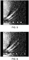
- FIGS. 5 and 6 are exemplary images of a weld ripple shape and fillet geometry.
- the release of a refractory silicate island disrupts the clean, consistent 2:00-to-8:00 ripple pattern shown in FIG. 5 , and significantly alters the polynomial-fit parameters that best characterize this shape.
- Such a silicate also appears as a large axial-circumferential defect in an ultrasonic inspection.
- the magnitude of a deviation in fit parameters is correlated with the defect size determined by ultrasonic inspection of a defect at the same location in a given weld during the learning phase. This correlation forms the basis of the probabilistic estimate that a defect has been produced during the production phase of the system.
- Defects in the weld are characterized (S5). That is, they are sized by ultrasonic methods and/or exposed and measured by destructive methods such as metallography. The characterized defects are correlated or matched with deviations in the captured images (S6).
- weld defects are detected in real-time. While the production weld is formed (S8), the first and second cameras 20, 22 capture images of the production weld molten pool and the production weld ripple shape and fillet geometry, respectively (S9).
- the captured images are processed relative to, among other things, the images and correlations processed during the learning phase (S10), and an aggregate probability that a weld position corresponding to the captured images contains a defect is computed based on the characterized defects correlated at least in the learning phase (S11). Aggregate probability is a blended, weighted probability based on image analysis from the several cameras, as well as the process-parameter data gathered by the weld station.
- a sudden change in arc-voltage corresponding to a change in the distance between the tungsten and the workpiece may indicate a 20% chance that a silicate defect has been produced; meanwhile, video analysis may suggest a 35% chance that a silicate has been produced.
- video analysis may suggest a 35% chance that a silicate has been produced.
- either of these two data points may not be sufficient to warrant investigation by the welders, but a near-simultaneous occurrence of these two events increases the aggregate probability tremendously.
- the system computes an aggregate probability, in real-time, that a given weld position contains a defect.
- the system is configured to raise alarms or possibly shut down welding depending on the likelihood that a defect has been created.
- the system defines threshold shape deviations for the weld molten pool (edges) and the weld ripple shape and fillet geometry.
- FIG. 4 is an exemplary camera image of the weld molten pool, showing the system identifying a shape of the edges via image processing.
- FIGS. 5 and 6 are exemplary views of the weld ripple shape and fillet geometry being identified by the system in real-time. When the thresholds are exceeded, the system identifies a potential weld defect.
- the system improves the probability of defect detection, enabling operators to push flaw-size "envelopes" with more confidence that critical flaws will not escape the production facility. Additionally, the cycle time to repair a defect can be reduced from several weeks or more to as little as a few minutes. Still further, the system can permit the use of less experienced welders and/or can enable welding by fewer operators.
Landscapes
- Engineering & Computer Science (AREA)
- Physics & Mathematics (AREA)
- Mechanical Engineering (AREA)
- General Physics & Mathematics (AREA)
- Plasma & Fusion (AREA)
- General Health & Medical Sciences (AREA)
- Biochemistry (AREA)
- Analytical Chemistry (AREA)
- Immunology (AREA)
- Pathology (AREA)
- Chemical & Material Sciences (AREA)
- Life Sciences & Earth Sciences (AREA)
- Health & Medical Sciences (AREA)
- Robotics (AREA)
- Quality & Reliability (AREA)
- Acoustics & Sound (AREA)
- General Engineering & Computer Science (AREA)
- Computer Vision & Pattern Recognition (AREA)
- Signal Processing (AREA)
- Investigating Materials By The Use Of Optical Means Adapted For Particular Applications (AREA)
- Image Analysis (AREA)
- Length Measuring Devices By Optical Means (AREA)
- Turbine Rotor Nozzle Sealing (AREA)
- Butt Welding And Welding Of Specific Article (AREA)
Abstract
Description
- The invention relates to weld quality control and, more particularly, to in-process inspection of automated welding processes.
- Manufacturers of turbine rotors and similar devices may utilize gas-tungsten-arc welding of component parts. Such welding improves mechanical properties including the ability to join components having different base materials as is often desirable in high-performance machines. Welding a turbine rotor, however, can take dozens of hours, and in order for the weld operators to identify a potential problem (e.g., a pore, lack of fusion, large silicate island, etc.) before it is welded over on the next pass, the operators must pay careful attention to every pulse made by their torch. It is a difficult task for a human operator to pay such close attention for such a long period of time.
- Even assuming the weld operators may be capable of paying such close attention, weld operators typically do not have the experience to know exactly what they are looking for. An experienced welder may see features in the shape of the molten pool, the sidewall wetting geometry, the solidified ripple pattern and the solidified bead geometry that comparative amateurs do not see.
- Most weld defects - e.g., pores, inclusions, lack of fusion, etc. - cannot be detected until testing such as ultrasonic testing is conducted on a finished weld. Detecting weld defects at the time they are created would save significant costs and cycle time. It would thus be desirable to utilize a "tireless" computer to pay close attention to the millions of weld pulses over the course of several days that it takes to weld a turbine rotor. It would further be desirable to utilize a machine vision system that is properly trained to watch these critical welds.
- In an exemplary embodiment, a method of detecting weld defects in real time includes a step of conducting a mock-up welding operation in a learning phase. The mock-up welding operating includes the steps of welding a first part to a second part, capturing images of a weld molten pool, and capturing images of a weld ripple shape and fillet geometry. The captured images are correlated with a weld position, and weld testing is performed on a weld resulting from the mock-up welding operation. Any defects in the weld are characterized, and the characterized defects are correlated with deviations in the captured images. During a production weld operation, the first camera captures images of a production weld molten pool, and the second camera captures images of a product weld ripple shape and fillet geometry. The captured images are processed to compute an aggregate probability that a weld position corresponding to the captured images contains a defect based on the correlated characterized defects.
- In another exemplary embodiment, a method of detecting weld defects in real time includes the steps of (a) correlating potential weld defects with images of a mock weld molten pool and images of a mock weld ripple shape and fillet geometry; (b) depositing weld metal into an annular groove in a production weld operation; (c) a first camera capturing images of a production weld molten pool during the production weld operation; (d) a second camera capturing images of a production weld ripple shape and fillet geometry during the production weld operation; and (e) processing the images captured in (c) and (d) and computing an aggregate probability that a weld position corresponding to the images captured in (c) and (d) contains a defect based on the potential defects correlated in (a).
- In still another exemplary embodiment, a system for detecting weld defects in real time includes a welding torch that enables weld metal to be deposited into an annular groove in a production weld operation, and first and second cameras. The first camera is positioned adjacent the welding torch and adjacent a part to be welded and captures images of a production weld molten pool during the production weld operation. The second camera is positioned farther from the welding torch than the first camera and downstream from the welding torch and captures images of a production weld ripple shape and fillet geometry during the production weld operation. A processor receives the images captured by the first and second cameras. The processor communicates with a database that stores correlated potential weld defects with images of a mock weld molten pool and images of a mock weld ripple shape and fillet geometry. The processor is programmed to process the images captured by the first and second cameras and to compute an aggregate probability that a weld position corresponding to the images captured by the first and second cameras contains a defect based on the potential defects correlated in the database.
-
-
FIGS. 1 and 2 are schematic illustrations showing the components for automated in-process inspection of welds; -
FIG. 3 is a flow diagram of the method for detecting weld defects in real time; -
FIG. 4 is an exemplary image of a weld molten pool; and -
FIGS. 5-6 are exemplary images of a weld ripple shape and fillet geometry. - The system performs in-process (i.e., real-time) inspection of automated welding processes such as a process for welding a turbine rotor. As described in more detail below, the system includes digital cameras that collect video data in real-time, sensors that monitor process data (amps, volts, temperatures, etc.) in real-time, and an inspection/testing system that is used off-line during a learning phase. During the learning phase, the system correlates features in the video and/or process data with defects and "indications" detected by testing. In operation, the system analyzes real-time streams and computes a probability at any given moment that a defect has been created. Based on configurable probability thresholds, welding can be suspended for re-work as soon as the system detects a high probability that a defect has been produced.
-
FIGS. 1 and 2 are schematic diagrams of the system for detecting weld defects in real-time. For purposes of the present description, weld metal is deposited into anannular groove 12 between afirst part 14 and asecond part 16. One or morewelding torches 18, such as TIG (tungsten inert gas) welding torches for example, may be positioned adjacent thegroove 12. In some embodiments, thewelding torches 18 are held stationary, while the first andsecond parts welding torches 18 may be displaced circumferentially around thegroove 12. Thewelding torches 18 include known sensors for weld data to measure physical characteristics of the weld, including, without limitation, gas flow values, temperature, welding current, voltage between torch and metal, circumferential position, radial position, etc. - A
first camera 20 is positioned adjacent eachwelding torch 18 near theannular groove 12. Asecond camera 22 is positioned generally farther from eachwelding torch 18 than thefirst cameras 20 and downstream from thewelding torches 18. By virtue of their proximity to the weld, thefirst cameras 20 must be able to withstand the high temperatures near thewelding torches 18. Thesecond cameras 22 are positioned farther from the heat generated by thetorches 18 and thus do not require the same degree of heat resistance. Thecameras - A
processor 24 receives the images captured by the first andsecond cameras database 26 communicates with theprocessor 24 and stores correlated potential weld defects with images of a mock weld molten pool and images of a mock weld ripple shape and fillet geometry from a learning phase (described below). - The
first cameras 20 capture images including the edges of the molten weld pool, and thesecond cameras 22 capture downstream images of the solidified weld ripple and fillet geometry. Additional first cameras may be utilized to capture images of both the leading edge of the molten pool and the trailing edge of the molten pool. Sensors associated with thetorches 18 collect the weld process data. Thecameras - As a non-limiting example, edge-detection operators such as the well-known "Canny algorithm" may be used on frames of video to locate the boundaries of the weld pool, as illustrated by the curved white lines in
FIG. 4 . In terms of a suitable x-y coordinate system, the white lines delineating the leading edge of the weld pool inFIG. 4 are fit to a mathematical function such as an Nth-order polynomial. The mathematical fit parameters that approximate the shape of the leading edge of the pool in one video frame are compared with fit parameters of the same feature from reference ("learning phase") video and/or adjacent frames in the same video. Deviations from the norm, or unexpected sudden changes in the fit parameters are used to identify and quantify anomalous situations. - Process and video data are indexed to the weld position. In an exemplary application to the turbine rotor weld, weld metal is deposited in dozens of overlapping passes by the
torches 18 that fill theannular groove 12 outward. In this context, weld position is determined by a circumferential angle and a radial depth. - With reference to
FIG. 3 , during a learning phase (Step S1), a mock welding operation is conducted (S2). Thefirst camera 20 captures images of the weld molten pool, and thesecond camera 22 captures images of the weld ripple shape and fillet geometry (S3). The captured images are correlated with a weld position (S4), and weld testing is performed on the resulting mock weld. The welds may be inspected off-line by ultrasonic testing and/or destructive methods to characterize any contained defect indications. For example, the testing can determine at each weld position defect size, type (pore, inclusion, lack of fusion, etc.), orientation (radial-axial, radial-circumferential, etc.), location (sidewall, surface-connected, etc.), etc. Analytical algorithms correlate features in the parameterized video and process data with indications observed by inspection.FIGS. 5 and 6 are exemplary images of a weld ripple shape and fillet geometry. As an example, the release of a refractory silicate island disrupts the clean, consistent 2:00-to-8:00 ripple pattern shown inFIG. 5 , and significantly alters the polynomial-fit parameters that best characterize this shape. Such a silicate also appears as a large axial-circumferential defect in an ultrasonic inspection. The magnitude of a deviation in fit parameters is correlated with the defect size determined by ultrasonic inspection of a defect at the same location in a given weld during the learning phase. This correlation forms the basis of the probabilistic estimate that a defect has been produced during the production phase of the system. Defects in the weld are characterized (S5). That is, they are sized by ultrasonic methods and/or exposed and measured by destructive methods such as metallography. The characterized defects are correlated or matched with deviations in the captured images (S6). - During the production weld process, weld defects are detected in real-time. While the production weld is formed (S8), the first and
second cameras - It is possible during the learning phase to deliberately run the welding process outside normal parameters and artificially create defects to help train the system. In some cases, such as an inclusion produced when a silicate is shed from the weld pool and later welded over, the task of correlating video and process data with embedded defects has a high level of accuracy, leading to high-probability links between the data and the defect. In other cases, such as the subtle stack-up of several weld parameters that cause a sidewall lack of fusion, may be more difficult to identify by analytics, leading to low-probability correlations.
- During production welding, the system computes an aggregate probability, in real-time, that a given weld position contains a defect. The system is configured to raise alarms or possibly shut down welding depending on the likelihood that a defect has been created. The system defines threshold shape deviations for the weld molten pool (edges) and the weld ripple shape and fillet geometry.
FIG. 4 is an exemplary camera image of the weld molten pool, showing the system identifying a shape of the edges via image processing.FIGS. 5 and 6 are exemplary views of the weld ripple shape and fillet geometry being identified by the system in real-time. When the thresholds are exceeded, the system identifies a potential weld defect. Most critical welds that could benefit from this system involve post-weld nondestructive testing. It is thus possible to continue the learning phase and refine the system calculation tools after each production weld. That is, each set of data can be correlated with video and process data to improve the tools for identifying weld defects. - The system improves the probability of defect detection, enabling operators to push flaw-size "envelopes" with more confidence that critical flaws will not escape the production facility. Additionally, the cycle time to repair a defect can be reduced from several weeks or more to as little as a few minutes. Still further, the system can permit the use of less experienced welders and/or can enable welding by fewer operators.
- While the invention has been described in connection with what is presently considered to be the most practical and preferred embodiments, it is to be understood that the invention is not to be limited to the disclosed embodiments, but on the contrary, is intended to cover various modifications and equivalent arrangements included within the spirit and scope of the appended claims.
- Various aspects and embodiments of the present invention are defined by the following clauses:
- 1. A method of detecting weld defects in real time, the method comprising:
- (a) conducting a mock-up welding operation in a learning phase including,
- (1) using a welding torch, welding a first part to a second part,
- (2) a first camera capturing images of a weld molten pool,
- (3) a second camera capturing images of a weld ripple shape and fillet geometry,
- (4) correlating the images captured in (2) and (3) with a weld position,
- (5) performing weld testing on a weld resulting from the welding in (1) and characterizing any defects in the weld, and
- (6) correlating the characterized defects with deviations in the images captured in (2) and (3); and
- (b) the first camera capturing images of a production weld molten pool during a production weld operation;
- (c) the second camera capturing images of a product weld ripple shape and fillet geometry during the production weld operation; and
- (d) processing the images captured in (b) and (c) and computing an aggregate probability that a weld position corresponding to the images captured in (b) and (c) contains a defect based on the characterized defects correlated in (6).
- (a) conducting a mock-up welding operation in a learning phase including,
- 2. A method according to
clause 1, further comprising, after step (d), outputting an alert or disabling the production weld operation based on the aggregate probability. - 3. A method according to
clause 1, wherein step (a)(6) is practiced by parameterizing a shape of the weld molten pool and the weld ripple shape and fillet geometry. - 4. A method according to clause 3, further comprising, before step (a)(4), capturing images of a shape and location of refractory contaminants in the weld motel pool, and wherein step (a)(6) further comprises parameterizing the shape and location of the refractory contaminants.
- 5. A method according to
clause 1, further comprising repeating steps (a)(2)-(a)(6) using the images captured in (b) and (c). - 6. A method according to
clause 1, wherein the production weld operation is performed by depositing weld metal in a plurality of overlapping passes by TIG torches that fill an annular groove in a turbine rotor, and wherein the weld position is determined by a circumferential angle and a radial depth. - 7. A method according to
clause 1, wherein step (a)(5) is practiced offline by ultrasonic testing or by destructive testing methods. - 8. A method according to
clause 1, wherein step (a)(1) is practiced to deliberately perform the welding step outside of normal parameters to artificially create defects. - 9. A method according to
clause 1, wherein step (a)(6) is practiced by defining threshold shape deviations for the weld molten pool and the weld ripple shape and fillet geometry. - 10. A method of detecting weld defects in real time, the method comprising:
- (a) correlating potential weld defects with images of a mock weld molten pool and images of a mock weld ripple shape and fillet geometry;
- (b) depositing weld metal into an annular groove in a production weld operation;
- (c) a first camera capturing images of a production weld molten pool during the production weld operation;
- (d) a second camera capturing images of a production weld ripple shape and fillet geometry during the production weld operation; and
- (e) processing the images captured in (c) and (d) and computing an aggregate probability that a weld position corresponding to the images captured in (c) and (d) contains a defect based on the potential defects correlated in (a).
- 11. A method according to
clause 10, further comprising, after step (e), outputting an alert or disabling the production weld operation based on the aggregate probability. - 12. A method according to
clause 10, further comprising performing weld testing on a weld resulting from the depositing in (b), and correlating additional weld defects using the images captured in (c) and (d). - 13. A method according to
clause 10, wherein the production weld operation is performed by depositing weld metal in a plurality of overlapping passes by TIG torches that fill the annular groove in a turbine rotor, and wherein a weld position is determined by a circumferential angle and a radial depth. - 14. A method according to
clause 10, wherein step (e) is practiced by analyzing an edge shape of the production weld molten pool. - 15. A method according to
clause 14, wherein step (e) is practiced by analyzing a leading edge shape of the production weld molten pool and a trailing edge shape of the production weld molten pool. - 16. A system for detecting weld defects in real time, the system comprising:
- a welding torch that enables weld metal to be deposited into an annular groove in a production weld operation;
- a first camera positioned adjacent the welding torch and adjacent a part to be welded, the first camera capturing images of a production weld molten pool during the production weld operation;
- a second camera positioned farther from the welding torch than the first camera and downstream from the welding torch, the second camera capturing images of a production weld ripple shape and fillet geometry during the production weld operation;
- a processor receiving the images captured by the first and second cameras;
and - a database storing correlated potential weld defects with images of a mock weld molten pool and images of a mock weld ripple shape and fillet geometry,
- wherein the processor communicates with the database and is programmed to process the images captured by the first and second cameras and to compute an aggregate probability that a weld position corresponding to the images captured by the first and second cameras contains a defect based on the potential defects correlated in the database.
- 17. A system according to
clause 16, wherein the first camera comprises two cameras including a leading edge camera that is positioned to capture images of the molten pool leading edge, and a trailing edge camera that is positioned to capture images of the molten pool trailing edge. - 18. A system according to
clause 16, wherein the annular groove is defined in a turbine rotor, wherein the weld metal is deposited in a plurality of overlapping passes by TIG torches that fill the annular groove in the turbine rotor, and wherein a weld position is determined by a circumferential angle and a radial depth.
Claims (15)
- A method of detecting weld defects in real time, the method comprising:(a) conducting a mock-up welding operation in a learning phase including,(1) using a welding torch, welding a first part (14) to a second part (16),(2) a first camera (20) capturing images of a weld molten pool,(3) a second camera (22) capturing images of a weld ripple shape and fillet geometry,(4) correlating the images captured in (2) and (3) with a weld position,(5) performing weld testing on a weld resulting from the welding in (1) and characterizing any defects in the weld, and(6) correlating the characterized defects with deviations in the images captured in (2) and (3); and(b) the first camera capturing images of a production weld molten pool during a production weld operation;(c) the second camera capturing images of a product weld ripple shape and fillet geometry during the production weld operation; and(d) processing the images captured in (b) and (c) and computing an aggregate probability that a weld position corresponding to the images captured in (b) and (c) contains a defect based on the characterized defects correlated in (6).
- A method of claim 1, further comprising, after step (d), outputting an alert or disabling the production weld operation based on the aggregate probability.
- A method of claim 1 or claim 2, wherein step (a)(6) is practiced by parameterizing a shape of the weld molten pool and the weld ripple shape and fillet geometry.
- A method of claim 3, further comprising, before step (a)(4), capturing images of a shape and location of refractory contaminants in the weld motel pool, and wherein step (a)(6) further comprises parameterizing the shape and location of the refractory contaminants.
- A method of any preceding claims, further comprising repeating steps (a)(2)-(a)(6) using the images captured in (b) and (c).
- A method of claim 1, wherein the production weld operation is performed by depositing weld metal in a plurality of overlapping passes by TIG torches that fill an annular groove (12) in a turbine rotor, and wherein the weld position is determined by a circumferential angle and a radial depth.
- A method of claim 1, wherein step (a)(5) is practiced offline by ultrasonic testing or by destructive testing methods.
- A method of claim 1, wherein step (a)(1) is practiced to deliberately perform the welding step outside of normal parameters to artificially create defects.
- A method of claim 1, wherein step (a)(6) is practiced by defining threshold shape deviations for the weld molten pool and the weld ripple shape and fillet geometry.
- A method of detecting weld defects in real time, the method comprising:(a) correlating potential weld defects with images of a mock weld molten pool and images of a mock weld ripple shape and fillet geometry;(b) depositing weld metal into an annular groove (12) in a production weld operation;(c) a first camera (20) capturing images of a production weld molten pool during the production weld operation;(d) a second camera (22) capturing images of a production weld ripple shape and fillet geometry during the production weld operation; and(e) processing the images captured in (c) and (d) and computing an aggregate probability that a weld position corresponding to the images captured in (c) and (d) contains a defect based on the potential defects correlated in (a).
- A method of claim 10, wherein step (e) is practiced by analyzing an edge shape of the production weld molten pool.
- A method of claim 11, wherein step (e) is practiced by analyzing a leading edge shape of the production weld molten pool and a trailing edge shape of the production weld molten pool.
- A system for detecting weld defects in real time, the system comprising:a welding torch (18) that enables weld metal to be deposited into an annular groove (12) in a production weld operation;a first camera (20) positioned adjacent the welding torch and adjacent a part to be welded, the first camera capturing images of a production weld molten pool during the production weld operation;a second camera (22) positioned farther from the welding torch than the first camera and downstream from the welding torch, the second camera capturing images of a production weld ripple shape and fillet geometry during the production weld operation;a processor (24) receiving the images captured by the first and second cameras;
anda database (26) storing correlated potential weld defects with images of a mock weld molten pool and images of a mock weld ripple shape and fillet geometry,wherein the processor (24) communicates with the database (26) and is programmed to process the images captured by the first (20) and second (22) cameras and to compute an aggregate probability that a weld position corresponding to the images captured by the first and second cameras contains a defect based on the potential defects correlated in the database (26). - A system of claim 13, wherein the first camera (20) comprises two cameras including a leading edge camera that is positioned to capture images of the molten pool leading edge, and a trailing edge camera that is positioned to capture images of the molten pool trailing edge.
- A system of claim 13, wherein the annular groove (12) is defined in a turbine rotor, wherein the weld metal is deposited in a plurality of overlapping passes by TIG torches (18) that fill the annular groove in the turbine rotor, and wherein a weld position is determined by a circumferential angle and a radial depth.
Priority Applications (1)
| Application Number | Priority Date | Filing Date | Title |
|---|---|---|---|
| PL16201012T PL3176537T3 (en) | 2015-12-01 | 2016-11-29 | System for automated in-process inspection of welds |
Applications Claiming Priority (1)
| Application Number | Priority Date | Filing Date | Title |
|---|---|---|---|
| US14/955,348 US10682729B2 (en) | 2015-12-01 | 2015-12-01 | System for automated in-process inspection of welds |
Publications (2)
| Publication Number | Publication Date |
|---|---|
| EP3176537A1 true EP3176537A1 (en) | 2017-06-07 |
| EP3176537B1 EP3176537B1 (en) | 2019-11-27 |
Family
ID=57442496
Family Applications (1)
| Application Number | Title | Priority Date | Filing Date |
|---|---|---|---|
| EP16201012.8A Active EP3176537B1 (en) | 2015-12-01 | 2016-11-29 | System for automated in-process inspection of welds |
Country Status (5)
| Country | Link |
|---|---|
| US (1) | US10682729B2 (en) |
| EP (1) | EP3176537B1 (en) |
| JP (1) | JP2017106908A (en) |
| CN (1) | CN106990111A (en) |
| PL (1) | PL3176537T3 (en) |
Cited By (5)
| Publication number | Priority date | Publication date | Assignee | Title |
|---|---|---|---|---|
| WO2019025556A1 (en) * | 2017-08-04 | 2019-02-07 | Fraunhofer-Gesellschaft zur Förderung der angewandten Forschung e.V. | METHOD FOR DETECTING AND IDENTIFYING COMPONENTS ASSOCIATED WITH A JOINTING METHOD |
| GB2570377A (en) * | 2017-12-28 | 2019-07-24 | Hitachi Ge Nuclear Energy Ltd | Defect inspection method and defect inspection system |
| EP3326749B1 (en) | 2016-11-26 | 2019-11-13 | Agie Charmilles SA | Method for machining and inspecting of workpieces |
| CN112222690A (en) * | 2020-09-30 | 2021-01-15 | 中石化第四建设有限公司 | Method for establishing pipeline weld joint management information |
| US12053842B2 (en) | 2019-11-27 | 2024-08-06 | Jfe Steel Corporation | Weld inspection apparatus |
Families Citing this family (31)
| Publication number | Priority date | Publication date | Assignee | Title |
|---|---|---|---|---|
| JP6792129B2 (en) * | 2017-03-03 | 2020-11-25 | 株式会社安川電機 | Arc welding system and arc welding judgment device |
| US10955814B2 (en) * | 2017-04-24 | 2021-03-23 | Autodesk, Inc. | Closed-loop robotic deposition of material |
| CN109975302B (en) * | 2017-12-28 | 2021-06-18 | 中核建中核燃料元件有限公司 | Automatic detection device of grillwork outward appearance of brazing |
| KR102579904B1 (en) | 2018-01-31 | 2023-09-19 | 삼성전자주식회사 | Method of managing vision inspection and vision inspection system |
| GB2573764A (en) * | 2018-05-15 | 2019-11-20 | Rolls Royce Plc | Method of evaluating a composite sample |
| CN109093227A (en) * | 2018-10-25 | 2018-12-28 | 江苏阀邦半导体材料科技有限公司 | A kind of automatic more quadrant mould group welding systems |
| CN111612730B (en) * | 2019-02-23 | 2022-04-22 | 妙微(杭州)科技有限公司 | Welding seam detection and positioning method |
| JP7198729B2 (en) | 2019-06-06 | 2023-01-04 | 株式会社日立製作所 | Welding work measurement system |
| JP7329754B2 (en) * | 2019-06-14 | 2023-08-21 | パナソニックIpマネジメント株式会社 | Repair welding system and repair welding method |
| CN110449696A (en) * | 2019-06-26 | 2019-11-15 | 中车工业研究院有限公司 | Welding system and welding method |
| JP7261682B2 (en) * | 2019-07-17 | 2023-04-20 | 株式会社日立製作所 | Welding work data storage device, welding work support system and welding robot control device |
| DK3815884T3 (en) * | 2019-10-30 | 2024-11-11 | Fischer G Rohrleitungssysteme Ag | PROCEDURE FOR CHECKING A WELD |
| CN114746207B (en) * | 2019-12-06 | 2023-06-20 | 松下知识产权经营株式会社 | Repair welding equipment and repair welding method |
| US12146872B2 (en) * | 2020-03-30 | 2024-11-19 | Hitachi Rail S.P.A. | Method and system for monitoring and identifying the weld quality on metallic components |
| US12399487B2 (en) * | 2020-04-08 | 2025-08-26 | BWXT Advanced Technologies LLC | In-situ inspection method based on digital data model of weld |
| CN112129774B (en) * | 2020-09-22 | 2023-08-29 | 哈尔滨工业大学(威海) | Welding unfused defect online detection method |
| JP7420692B2 (en) | 2020-10-16 | 2024-01-23 | 株式会社神戸製鋼所 | Welding system, welding method, welding support device, program, learning device, and learned model generation method |
| CN112453751B (en) * | 2020-11-27 | 2022-07-15 | 上海交通大学 | An online monitoring method for the backside of pipeline all-position welding based on visual sensing |
| EP4019177A1 (en) * | 2020-12-22 | 2022-06-29 | FRONIUS INTERNATIONAL GmbH | Method and device for assessing the quality of a processing process |
| CN112756840A (en) * | 2021-01-25 | 2021-05-07 | 陕西帕源路桥建设有限公司 | Welding quality detection system |
| CN113192573B (en) * | 2021-03-29 | 2023-02-21 | 中车青岛四方机车车辆股份有限公司 | Visual Analysis Method of Melt Pool Flow Behavior |
| JP7038876B1 (en) | 2021-05-18 | 2022-03-18 | 日鉄エンジニアリング株式会社 | Welding system, welding method and program |
| CN113567433A (en) * | 2021-06-09 | 2021-10-29 | 中车青岛四方机车车辆股份有限公司 | Method and device for detecting bonded joint |
| GB202110597D0 (en) * | 2021-07-23 | 2021-09-08 | Rolls Royce Plc | System and method for welding components |
| JP7726713B2 (en) * | 2021-09-21 | 2025-08-20 | 株式会社東芝 | Processing equipment and welding system |
| CN114820499A (en) * | 2022-04-20 | 2022-07-29 | 上海电气集团股份有限公司 | Pipeline welding seam detection method |
| CN115268266A (en) * | 2022-07-22 | 2022-11-01 | 哈尔滨工业大学 | Quality evaluation system for welding of thrust chamber |
| CN116337872A (en) * | 2023-03-27 | 2023-06-27 | 西安交通大学 | An online monitoring method and device for arc welding forming defects |
| KR102753795B1 (en) * | 2024-11-01 | 2025-01-16 | 브이에프스페이스 주식회사 | Melt Pool Analysis Method for 3D Metal Additive Manufacturing |
| CN120609831B (en) * | 2025-08-07 | 2025-10-14 | 艾克森(苏州)传热技术有限公司 | All-welded heat exchanger industrial detection method and system based on machine vision |
| CN120807510B (en) * | 2025-09-12 | 2025-12-05 | 陕西金鑫电器有限公司 | An image localization method for defects in welded joints of aluminum alloy shells |
Citations (3)
| Publication number | Priority date | Publication date | Assignee | Title |
|---|---|---|---|---|
| US20040124227A1 (en) * | 2001-02-14 | 2004-07-01 | Honda Giken Kogyo Kabushiki Kaisha | Welding condition monitoring device |
| JP2009125790A (en) * | 2007-11-27 | 2009-06-11 | Kobe Steel Ltd | Monitoring apparatus of arc welding |
| US20150056585A1 (en) * | 2012-07-06 | 2015-02-26 | Ewi, Inc. | System and method monitoring and characterizing manual welding operations |
Family Cites Families (27)
| Publication number | Priority date | Publication date | Assignee | Title |
|---|---|---|---|---|
| JPS5499754A (en) * | 1978-01-25 | 1979-08-06 | Hitachi Ltd | Method and apparatus for automatic control of arc welding |
| US4595820A (en) * | 1982-10-22 | 1986-06-17 | The Ohio State University | Apparatus and methods for controlling a welding process |
| US5061841A (en) * | 1982-10-22 | 1991-10-29 | The Ohio State University | Apparatus and methods for controlling a welding process |
| US4739404A (en) * | 1982-10-22 | 1988-04-19 | The Ohio State University | Apparatus and methods for controlling a welding process |
| US4532408A (en) * | 1982-10-22 | 1985-07-30 | The Ohio State University | Apparatus and method for viewing molten pools in arc welding |
| US4943702A (en) * | 1982-10-22 | 1990-07-24 | The Ohio State University | Apparatus and methods for controlling a welding process |
| US4491719A (en) * | 1982-12-20 | 1985-01-01 | General Electric Company | Light pattern projector especially for welding |
| US4649426A (en) * | 1984-06-12 | 1987-03-10 | The United States Of America As Represented By The United States Department Of Energy | Electronic imaging system and technique |
| US4578561A (en) * | 1984-08-16 | 1986-03-25 | General Electric Company | Method of enhancing weld pool boundary definition |
| US4611111A (en) * | 1985-01-22 | 1986-09-09 | General Electric Company | Method to determine weld puddle area and width from vision measurements |
| US4711986A (en) * | 1986-11-24 | 1987-12-08 | General Electric Company | Method and apparatus for measuring weld penetration in an arc welding process |
| US4767911A (en) * | 1987-02-26 | 1988-08-30 | Rockwell International Corporation | Optical weld contour monitor for penetration control |
| US5275327A (en) * | 1992-10-13 | 1994-01-04 | Eg&G Idaho, Inc. | Integrated optical sensor |
| JPH08240536A (en) * | 1995-01-03 | 1996-09-17 | Texas Instr Inc <Ti> | Method and apparatus for inspecting leads for burrs in integrated circuits |
| US5793009A (en) * | 1996-06-20 | 1998-08-11 | General Electric Company | Apparatus for joining metal components using broad, thin filler nozzle |
| US6084205A (en) * | 1997-03-14 | 2000-07-04 | Sandia Corporation | Method for enhanced control of welding processes |
| US7006669B1 (en) * | 2000-12-31 | 2006-02-28 | Cognex Corporation | Machine vision method and apparatus for thresholding images of non-uniform materials |
| US7375304B2 (en) * | 2001-01-25 | 2008-05-20 | Lincoln Global, Inc. | System and method providing automated welding notification |
| US6795778B2 (en) * | 2001-05-24 | 2004-09-21 | Lincoln Global, Inc. | System and method for facilitating welding system diagnostics |
| US6701615B2 (en) * | 2002-03-08 | 2004-03-09 | General Electric Company | Inspection and sorting system and method for part repair |
| US7590276B2 (en) | 2004-12-20 | 2009-09-15 | Mitutoyo Corporation | System and method for programming interrupting operations during moving image acquisition sequences in a vision system |
| US8144193B2 (en) * | 2009-02-09 | 2012-03-27 | Recognition Robotics, Inc. | Work piece tracking system and method |
| CA2821671C (en) * | 2010-12-13 | 2018-01-09 | Edison Welding Institute, Inc. | Welding training system |
| JP2013207439A (en) * | 2012-03-28 | 2013-10-07 | Mitsubishi Heavy Ind Ltd | Imaging device for welding |
| US9604301B2 (en) * | 2012-11-13 | 2017-03-28 | Yuming Zhang | Method to monitor and control weld penetration in gas tungsten welding and full-position pipe welding |
| US9836987B2 (en) * | 2014-02-14 | 2017-12-05 | Lincoln Global, Inc. | Virtual reality pipe welding simulator and setup |
| US20150248845A1 (en) * | 2014-02-28 | 2015-09-03 | Lincoln Global, Inc. | Portable virtual welding system |
-
2015
- 2015-12-01 US US14/955,348 patent/US10682729B2/en active Active
-
2016
- 2016-11-16 JP JP2016223389A patent/JP2017106908A/en active Pending
- 2016-11-29 PL PL16201012T patent/PL3176537T3/en unknown
- 2016-11-29 EP EP16201012.8A patent/EP3176537B1/en active Active
- 2016-12-01 CN CN201611090751.2A patent/CN106990111A/en active Pending
Patent Citations (3)
| Publication number | Priority date | Publication date | Assignee | Title |
|---|---|---|---|---|
| US20040124227A1 (en) * | 2001-02-14 | 2004-07-01 | Honda Giken Kogyo Kabushiki Kaisha | Welding condition monitoring device |
| JP2009125790A (en) * | 2007-11-27 | 2009-06-11 | Kobe Steel Ltd | Monitoring apparatus of arc welding |
| US20150056585A1 (en) * | 2012-07-06 | 2015-02-26 | Ewi, Inc. | System and method monitoring and characterizing manual welding operations |
Cited By (8)
| Publication number | Priority date | Publication date | Assignee | Title |
|---|---|---|---|---|
| EP3326749B1 (en) | 2016-11-26 | 2019-11-13 | Agie Charmilles SA | Method for machining and inspecting of workpieces |
| EP3326749B2 (en) † | 2016-11-26 | 2025-11-12 | Agie Charmilles SA | Method for machining and inspecting of workpieces |
| WO2019025556A1 (en) * | 2017-08-04 | 2019-02-07 | Fraunhofer-Gesellschaft zur Förderung der angewandten Forschung e.V. | METHOD FOR DETECTING AND IDENTIFYING COMPONENTS ASSOCIATED WITH A JOINTING METHOD |
| GB2570377A (en) * | 2017-12-28 | 2019-07-24 | Hitachi Ge Nuclear Energy Ltd | Defect inspection method and defect inspection system |
| GB2570377B (en) * | 2017-12-28 | 2020-07-01 | Hitachi Ge Nuclear Energy Ltd | Defect inspection method and defect inspection system |
| US12053842B2 (en) | 2019-11-27 | 2024-08-06 | Jfe Steel Corporation | Weld inspection apparatus |
| CN112222690A (en) * | 2020-09-30 | 2021-01-15 | 中石化第四建设有限公司 | Method for establishing pipeline weld joint management information |
| CN112222690B (en) * | 2020-09-30 | 2022-08-30 | 中石化第四建设有限公司 | Method for establishing pipeline weld joint management information |
Also Published As
| Publication number | Publication date |
|---|---|
| PL3176537T3 (en) | 2020-05-18 |
| JP2017106908A (en) | 2017-06-15 |
| CN106990111A (en) | 2017-07-28 |
| EP3176537B1 (en) | 2019-11-27 |
| US20170151634A1 (en) | 2017-06-01 |
| US10682729B2 (en) | 2020-06-16 |
Similar Documents
| Publication | Publication Date | Title |
|---|---|---|
| US10682729B2 (en) | System for automated in-process inspection of welds | |
| US12399487B2 (en) | In-situ inspection method based on digital data model of weld | |
| EP4234158A1 (en) | System and method for analyzing weld quality | |
| CN103231162A (en) | Device and method for visual detection of welding quality of robot | |
| US20210063316A1 (en) | Joining process line monitoring system | |
| Hamzeh et al. | A sensor based monitoring system for real-time quality control: Semi-automatic arc welding case study | |
| CN114147397B (en) | Automatic flexible point welding system for identifying 3D characteristics | |
| WO2022040819A2 (en) | Computer-implemented monitoring of a welding operation | |
| US12293511B2 (en) | Anomaly detection system in the automatic placement of composites during the manufacturing of structural elements | |
| WO2023188889A1 (en) | Welding control method for automatic welding, control device, welding system, program, and welding method | |
| JP7496080B2 (en) | Machine Tools | |
| CN112129774A (en) | An online detection method for welding unfused defects | |
| CN111811437A (en) | Band saw blade welding quality detection method and device | |
| Piecuch et al. | Diagnostics of welding process based on thermovision images using convolutional neural network | |
| CN109447403A (en) | A kind of welding defect analysis system and method based on big data | |
| Melakhsou et al. | Computer Vision based welding defect detection using YOLOv3 | |
| WO2024112737A1 (en) | Automated macrographic section analysis of joints | |
| Ayoade et al. | Heterogeneous measurement system for data mining robotic GMAW weld quality | |
| Soares et al. | Computer Vision System for Weld Bead Analysis. | |
| Couto et al. | Weld Bead Width Measurement in a GMAW WAAM System by using Passive Vision | |
| Bzymek | Application of selected method of anomaly detection in signals acquired during welding process monitoring | |
| Jeong et al. | Ensemble machine learning model for prediction of inner welding defects in orbital GTAW (Gas Tungsten Arc Welding) process with monitored by multi-sensor system | |
| Ajithkumar et al. | Advancements in Robotic Welding Sensing Technology: A Review | |
| CN109343445A (en) | A kind of poor counting of robot production line leakproof sequence and synchronous clearing control system | |
| KR20240032456A (en) | A welding defect comfirmation method of a seat frame for vehicle |
Legal Events
| Date | Code | Title | Description |
|---|---|---|---|
| AK | Designated contracting states |
Kind code of ref document: A1 Designated state(s): AL AT BE BG CH CY CZ DE DK EE ES FI FR GB GR HR HU IE IS IT LI LT LU LV MC MK MT NL NO PL PT RO RS SE SI SK SM TR |
|
| AX | Request for extension of the european patent |
Extension state: BA ME |
|
| PUAI | Public reference made under article 153(3) epc to a published international application that has entered the european phase |
Free format text: ORIGINAL CODE: 0009012 |
|
| STAA | Information on the status of an ep patent application or granted ep patent |
Free format text: STATUS: THE APPLICATION HAS BEEN PUBLISHED |
|
| STAA | Information on the status of an ep patent application or granted ep patent |
Free format text: STATUS: REQUEST FOR EXAMINATION WAS MADE |
|
| 17P | Request for examination filed |
Effective date: 20171207 |
|
| RBV | Designated contracting states (corrected) |
Designated state(s): AL AT BE BG CH CY CZ DE DK EE ES FI FR GB GR HR HU IE IS IT LI LT LU LV MC MK MT NL NO PL PT RO RS SE SI SK SM TR |
|
| GRAP | Despatch of communication of intention to grant a patent |
Free format text: ORIGINAL CODE: EPIDOSNIGR1 |
|
| STAA | Information on the status of an ep patent application or granted ep patent |
Free format text: STATUS: GRANT OF PATENT IS INTENDED |
|
| INTG | Intention to grant announced |
Effective date: 20190612 |
|
| GRAS | Grant fee paid |
Free format text: ORIGINAL CODE: EPIDOSNIGR3 |
|
| GRAA | (expected) grant |
Free format text: ORIGINAL CODE: 0009210 |
|
| STAA | Information on the status of an ep patent application or granted ep patent |
Free format text: STATUS: THE PATENT HAS BEEN GRANTED |
|
| AK | Designated contracting states |
Kind code of ref document: B1 Designated state(s): AL AT BE BG CH CY CZ DE DK EE ES FI FR GB GR HR HU IE IS IT LI LT LU LV MC MK MT NL NO PL PT RO RS SE SI SK SM TR |
|
| REG | Reference to a national code |
Ref country code: GB Ref legal event code: FG4D |
|
| REG | Reference to a national code |
Ref country code: CH Ref legal event code: EP |
|
| REG | Reference to a national code |
Ref country code: AT Ref legal event code: REF Ref document number: 1207161 Country of ref document: AT Kind code of ref document: T Effective date: 20191215 |
|
| REG | Reference to a national code |
Ref country code: DE Ref legal event code: R096 Ref document number: 602016024999 Country of ref document: DE |
|
| REG | Reference to a national code |
Ref country code: IE Ref legal event code: FG4D |
|
| REG | Reference to a national code |
Ref country code: NL Ref legal event code: MP Effective date: 20191127 |
|
| REG | Reference to a national code |
Ref country code: LT Ref legal event code: MG4D |
|
| PG25 | Lapsed in a contracting state [announced via postgrant information from national office to epo] |
Ref country code: LV Free format text: LAPSE BECAUSE OF FAILURE TO SUBMIT A TRANSLATION OF THE DESCRIPTION OR TO PAY THE FEE WITHIN THE PRESCRIBED TIME-LIMIT Effective date: 20191127 Ref country code: SE Free format text: LAPSE BECAUSE OF FAILURE TO SUBMIT A TRANSLATION OF THE DESCRIPTION OR TO PAY THE FEE WITHIN THE PRESCRIBED TIME-LIMIT Effective date: 20191127 Ref country code: BG Free format text: LAPSE BECAUSE OF FAILURE TO SUBMIT A TRANSLATION OF THE DESCRIPTION OR TO PAY THE FEE WITHIN THE PRESCRIBED TIME-LIMIT Effective date: 20200227 Ref country code: FI Free format text: LAPSE BECAUSE OF FAILURE TO SUBMIT A TRANSLATION OF THE DESCRIPTION OR TO PAY THE FEE WITHIN THE PRESCRIBED TIME-LIMIT Effective date: 20191127 Ref country code: NO Free format text: LAPSE BECAUSE OF FAILURE TO SUBMIT A TRANSLATION OF THE DESCRIPTION OR TO PAY THE FEE WITHIN THE PRESCRIBED TIME-LIMIT Effective date: 20200227 Ref country code: GR Free format text: LAPSE BECAUSE OF FAILURE TO SUBMIT A TRANSLATION OF THE DESCRIPTION OR TO PAY THE FEE WITHIN THE PRESCRIBED TIME-LIMIT Effective date: 20200228 Ref country code: LT Free format text: LAPSE BECAUSE OF FAILURE TO SUBMIT A TRANSLATION OF THE DESCRIPTION OR TO PAY THE FEE WITHIN THE PRESCRIBED TIME-LIMIT Effective date: 20191127 Ref country code: NL Free format text: LAPSE BECAUSE OF FAILURE TO SUBMIT A TRANSLATION OF THE DESCRIPTION OR TO PAY THE FEE WITHIN THE PRESCRIBED TIME-LIMIT Effective date: 20191127 |
|
| PG25 | Lapsed in a contracting state [announced via postgrant information from national office to epo] |
Ref country code: HR Free format text: LAPSE BECAUSE OF FAILURE TO SUBMIT A TRANSLATION OF THE DESCRIPTION OR TO PAY THE FEE WITHIN THE PRESCRIBED TIME-LIMIT Effective date: 20191127 Ref country code: IS Free format text: LAPSE BECAUSE OF FAILURE TO SUBMIT A TRANSLATION OF THE DESCRIPTION OR TO PAY THE FEE WITHIN THE PRESCRIBED TIME-LIMIT Effective date: 20200327 Ref country code: RS Free format text: LAPSE BECAUSE OF FAILURE TO SUBMIT A TRANSLATION OF THE DESCRIPTION OR TO PAY THE FEE WITHIN THE PRESCRIBED TIME-LIMIT Effective date: 20191127 |
|
| PGFP | Annual fee paid to national office [announced via postgrant information from national office to epo] |
Ref country code: CH Payment date: 20200123 Year of fee payment: 4 |
|
| PG25 | Lapsed in a contracting state [announced via postgrant information from national office to epo] |
Ref country code: AL Free format text: LAPSE BECAUSE OF FAILURE TO SUBMIT A TRANSLATION OF THE DESCRIPTION OR TO PAY THE FEE WITHIN THE PRESCRIBED TIME-LIMIT Effective date: 20191127 |
|
| PG25 | Lapsed in a contracting state [announced via postgrant information from national office to epo] |
Ref country code: RO Free format text: LAPSE BECAUSE OF FAILURE TO SUBMIT A TRANSLATION OF THE DESCRIPTION OR TO PAY THE FEE WITHIN THE PRESCRIBED TIME-LIMIT Effective date: 20191127 Ref country code: CZ Free format text: LAPSE BECAUSE OF FAILURE TO SUBMIT A TRANSLATION OF THE DESCRIPTION OR TO PAY THE FEE WITHIN THE PRESCRIBED TIME-LIMIT Effective date: 20191127 Ref country code: PT Free format text: LAPSE BECAUSE OF FAILURE TO SUBMIT A TRANSLATION OF THE DESCRIPTION OR TO PAY THE FEE WITHIN THE PRESCRIBED TIME-LIMIT Effective date: 20200419 Ref country code: EE Free format text: LAPSE BECAUSE OF FAILURE TO SUBMIT A TRANSLATION OF THE DESCRIPTION OR TO PAY THE FEE WITHIN THE PRESCRIBED TIME-LIMIT Effective date: 20191127 Ref country code: ES Free format text: LAPSE BECAUSE OF FAILURE TO SUBMIT A TRANSLATION OF THE DESCRIPTION OR TO PAY THE FEE WITHIN THE PRESCRIBED TIME-LIMIT Effective date: 20191127 Ref country code: DK Free format text: LAPSE BECAUSE OF FAILURE TO SUBMIT A TRANSLATION OF THE DESCRIPTION OR TO PAY THE FEE WITHIN THE PRESCRIBED TIME-LIMIT Effective date: 20191127 Ref country code: LU Free format text: LAPSE BECAUSE OF NON-PAYMENT OF DUE FEES Effective date: 20191129 |
|
| REG | Reference to a national code |
Ref country code: BE Ref legal event code: MM Effective date: 20191130 |
|
| REG | Reference to a national code |
Ref country code: DE Ref legal event code: R097 Ref document number: 602016024999 Country of ref document: DE |
|
| PG25 | Lapsed in a contracting state [announced via postgrant information from national office to epo] |
Ref country code: SK Free format text: LAPSE BECAUSE OF FAILURE TO SUBMIT A TRANSLATION OF THE DESCRIPTION OR TO PAY THE FEE WITHIN THE PRESCRIBED TIME-LIMIT Effective date: 20191127 Ref country code: SM Free format text: LAPSE BECAUSE OF FAILURE TO SUBMIT A TRANSLATION OF THE DESCRIPTION OR TO PAY THE FEE WITHIN THE PRESCRIBED TIME-LIMIT Effective date: 20191127 Ref country code: MC Free format text: LAPSE BECAUSE OF FAILURE TO SUBMIT A TRANSLATION OF THE DESCRIPTION OR TO PAY THE FEE WITHIN THE PRESCRIBED TIME-LIMIT Effective date: 20191127 |
|
| REG | Reference to a national code |
Ref country code: AT Ref legal event code: MK05 Ref document number: 1207161 Country of ref document: AT Kind code of ref document: T Effective date: 20191127 |
|
| PLBE | No opposition filed within time limit |
Free format text: ORIGINAL CODE: 0009261 |
|
| STAA | Information on the status of an ep patent application or granted ep patent |
Free format text: STATUS: NO OPPOSITION FILED WITHIN TIME LIMIT |
|
| PG25 | Lapsed in a contracting state [announced via postgrant information from national office to epo] |
Ref country code: IE Free format text: LAPSE BECAUSE OF NON-PAYMENT OF DUE FEES Effective date: 20191129 |
|
| 26N | No opposition filed |
Effective date: 20200828 |
|
| PG25 | Lapsed in a contracting state [announced via postgrant information from national office to epo] |
Ref country code: AT Free format text: LAPSE BECAUSE OF FAILURE TO SUBMIT A TRANSLATION OF THE DESCRIPTION OR TO PAY THE FEE WITHIN THE PRESCRIBED TIME-LIMIT Effective date: 20191127 Ref country code: BE Free format text: LAPSE BECAUSE OF NON-PAYMENT OF DUE FEES Effective date: 20191130 Ref country code: SI Free format text: LAPSE BECAUSE OF FAILURE TO SUBMIT A TRANSLATION OF THE DESCRIPTION OR TO PAY THE FEE WITHIN THE PRESCRIBED TIME-LIMIT Effective date: 20191127 |
|
| PG25 | Lapsed in a contracting state [announced via postgrant information from national office to epo] |
Ref country code: CY Free format text: LAPSE BECAUSE OF FAILURE TO SUBMIT A TRANSLATION OF THE DESCRIPTION OR TO PAY THE FEE WITHIN THE PRESCRIBED TIME-LIMIT Effective date: 20191127 |
|
| REG | Reference to a national code |
Ref country code: CH Ref legal event code: PL |
|
| GBPC | Gb: european patent ceased through non-payment of renewal fee |
Effective date: 20201129 |
|
| PG25 | Lapsed in a contracting state [announced via postgrant information from national office to epo] |
Ref country code: HU Free format text: LAPSE BECAUSE OF FAILURE TO SUBMIT A TRANSLATION OF THE DESCRIPTION OR TO PAY THE FEE WITHIN THE PRESCRIBED TIME-LIMIT; INVALID AB INITIO Effective date: 20161129 Ref country code: MT Free format text: LAPSE BECAUSE OF FAILURE TO SUBMIT A TRANSLATION OF THE DESCRIPTION OR TO PAY THE FEE WITHIN THE PRESCRIBED TIME-LIMIT Effective date: 20191127 |
|
| PG25 | Lapsed in a contracting state [announced via postgrant information from national office to epo] |
Ref country code: CH Free format text: LAPSE BECAUSE OF NON-PAYMENT OF DUE FEES Effective date: 20201130 Ref country code: LI Free format text: LAPSE BECAUSE OF NON-PAYMENT OF DUE FEES Effective date: 20201130 |
|
| PG25 | Lapsed in a contracting state [announced via postgrant information from national office to epo] |
Ref country code: GB Free format text: LAPSE BECAUSE OF NON-PAYMENT OF DUE FEES Effective date: 20201129 |
|
| PG25 | Lapsed in a contracting state [announced via postgrant information from national office to epo] |
Ref country code: TR Free format text: LAPSE BECAUSE OF FAILURE TO SUBMIT A TRANSLATION OF THE DESCRIPTION OR TO PAY THE FEE WITHIN THE PRESCRIBED TIME-LIMIT Effective date: 20191127 |
|
| PG25 | Lapsed in a contracting state [announced via postgrant information from national office to epo] |
Ref country code: MK Free format text: LAPSE BECAUSE OF FAILURE TO SUBMIT A TRANSLATION OF THE DESCRIPTION OR TO PAY THE FEE WITHIN THE PRESCRIBED TIME-LIMIT Effective date: 20191127 |
|
| REG | Reference to a national code |
Ref country code: DE Ref legal event code: R082 Ref document number: 602016024999 Country of ref document: DE Ref country code: DE Ref legal event code: R081 Ref document number: 602016024999 Country of ref document: DE Owner name: GENERAL ELECTRIC TECHNOLOGY GMBH, CH Free format text: FORMER OWNER: GENERAL ELECTRIC COMPANY, SCHENECTADY, NY, US |
|
| PGFP | Annual fee paid to national office [announced via postgrant information from national office to epo] |
Ref country code: FR Payment date: 20231019 Year of fee payment: 8 |
|
| PG25 | Lapsed in a contracting state [announced via postgrant information from national office to epo] |
Ref country code: FR Free format text: LAPSE BECAUSE OF NON-PAYMENT OF DUE FEES Effective date: 20241130 |
|
| PGFP | Annual fee paid to national office [announced via postgrant information from national office to epo] |
Ref country code: DE Payment date: 20251022 Year of fee payment: 10 |
|
| PGFP | Annual fee paid to national office [announced via postgrant information from national office to epo] |
Ref country code: IT Payment date: 20251022 Year of fee payment: 10 |
|
| PGFP | Annual fee paid to national office [announced via postgrant information from national office to epo] |
Ref country code: PL Payment date: 20251023 Year of fee payment: 10 |