EP3176331B1 - Vorrichtung und verfahren zur montage eines arbeitswerkzeugs an eine maschine - Google Patents
Vorrichtung und verfahren zur montage eines arbeitswerkzeugs an eine maschine Download PDFInfo
- Publication number
- EP3176331B1 EP3176331B1 EP16199591.5A EP16199591A EP3176331B1 EP 3176331 B1 EP3176331 B1 EP 3176331B1 EP 16199591 A EP16199591 A EP 16199591A EP 3176331 B1 EP3176331 B1 EP 3176331B1
- Authority
- EP
- European Patent Office
- Prior art keywords
- arm
- coupling
- work tool
- pin
- coupling means
- Prior art date
- Legal status (The legal status is an assumption and is not a legal conclusion. Google has not performed a legal analysis and makes no representation as to the accuracy of the status listed.)
- Active
Links
Images


Classifications
-
- E—FIXED CONSTRUCTIONS
- E02—HYDRAULIC ENGINEERING; FOUNDATIONS; SOIL SHIFTING
- E02F—DREDGING; SOIL-SHIFTING
- E02F3/00—Dredgers; Soil-shifting machines
- E02F3/04—Dredgers; Soil-shifting machines mechanically-driven
- E02F3/28—Dredgers; Soil-shifting machines mechanically-driven with digging tools mounted on a dipper- or bucket-arm, i.e. there is either one arm or a pair of arms, e.g. dippers, buckets
- E02F3/36—Component parts
- E02F3/3604—Devices to connect tools to arms, booms or the like
- E02F3/3609—Devices to connect tools to arms, booms or the like of the quick acting type, e.g. controlled from the operator seat
-
- E—FIXED CONSTRUCTIONS
- E02—HYDRAULIC ENGINEERING; FOUNDATIONS; SOIL SHIFTING
- E02F—DREDGING; SOIL-SHIFTING
- E02F3/00—Dredgers; Soil-shifting machines
- E02F3/04—Dredgers; Soil-shifting machines mechanically-driven
- E02F3/28—Dredgers; Soil-shifting machines mechanically-driven with digging tools mounted on a dipper- or bucket-arm, i.e. there is either one arm or a pair of arms, e.g. dippers, buckets
- E02F3/30—Dredgers; Soil-shifting machines mechanically-driven with digging tools mounted on a dipper- or bucket-arm, i.e. there is either one arm or a pair of arms, e.g. dippers, buckets with a dipper-arm pivoted on a cantilever beam, i.e. boom
- E02F3/32—Dredgers; Soil-shifting machines mechanically-driven with digging tools mounted on a dipper- or bucket-arm, i.e. there is either one arm or a pair of arms, e.g. dippers, buckets with a dipper-arm pivoted on a cantilever beam, i.e. boom working downwardly and towards the machine, e.g. with backhoes
-
- E—FIXED CONSTRUCTIONS
- E02—HYDRAULIC ENGINEERING; FOUNDATIONS; SOIL SHIFTING
- E02F—DREDGING; SOIL-SHIFTING
- E02F3/00—Dredgers; Soil-shifting machines
- E02F3/04—Dredgers; Soil-shifting machines mechanically-driven
- E02F3/28—Dredgers; Soil-shifting machines mechanically-driven with digging tools mounted on a dipper- or bucket-arm, i.e. there is either one arm or a pair of arms, e.g. dippers, buckets
- E02F3/36—Component parts
- E02F3/3604—Devices to connect tools to arms, booms or the like
- E02F3/3609—Devices to connect tools to arms, booms or the like of the quick acting type, e.g. controlled from the operator seat
- E02F3/3631—Devices to connect tools to arms, booms or the like of the quick acting type, e.g. controlled from the operator seat with a hook and a transversal locking element
-
- E—FIXED CONSTRUCTIONS
- E02—HYDRAULIC ENGINEERING; FOUNDATIONS; SOIL SHIFTING
- E02F—DREDGING; SOIL-SHIFTING
- E02F3/00—Dredgers; Soil-shifting machines
- E02F3/04—Dredgers; Soil-shifting machines mechanically-driven
- E02F3/28—Dredgers; Soil-shifting machines mechanically-driven with digging tools mounted on a dipper- or bucket-arm, i.e. there is either one arm or a pair of arms, e.g. dippers, buckets
- E02F3/36—Component parts
- E02F3/3604—Devices to connect tools to arms, booms or the like
- E02F3/3609—Devices to connect tools to arms, booms or the like of the quick acting type, e.g. controlled from the operator seat
- E02F3/3636—Devices to connect tools to arms, booms or the like of the quick acting type, e.g. controlled from the operator seat using two or four movable transversal pins
Definitions
- the current disclosure relates to engaging work tools to machines, and more particularly it relates to an apparatus and a method for assembling a work tool to an arm assembly of a machine.
- Machines such as, hydraulic excavators, hydraulic shovels, backhoe loaders and the like, are often required to perform different kinds of work on a work site. Therefore, different work tools, such as buckets, hammers, rippers, and grapples, may have to be engaged with an arm assembly (including, for example, sticks and booms) of the machine. It is known that the process of removing one work tool from the arm assembly and replacing the work tool with a different work tool may be a time consuming and difficult process.
- Quick couplers have been employed to enable quick engagement of the stick and the work tool and the quick couplers do, to an extent, reduce effort required for removing the work tool and replacing it. However, such quick couplers add weight to the stick end and build up the stick height/length. As a result, the machine's capabilities may be compromised.
- US Patent 7,014,385 B2 discloses an attachment coupling device for heavy machinery.
- the attachment coupling device is designed to releasably connect a variety of attachments to an arm and a push link of heavy machinery, such as hydraulic excavators.
- the attachment coupling device comprises a pair of mounting brackets fixedly secured to the attachment, each bracket having first and second hooks spaced apart with each other.
- a coupler which includes, a fixed plate affixed to the arm and the push link, a pair of fixed coupling pins each protruding outwardly from the fixed plate for engagement with the first hook of each of the mounting brackets, a pair of movable coupling pins for movement between a retracted release position and an extended coupling position, wherein the respective one of the movable pins comes into engagement with the second hook of each of the mounting brackets, and an actuator for causing movement of the movable coupling pins.
- U.S. Patent Pub. No. 2001051093 discloses a quick-coupling device for attaching a tool to an excavator comprising at least one main working arm.
- the quick-coupling device comprises a main body provided with two side walls each connected at the rear to this working arm by a pin housed in holes in the walls to allow it to be rotated relative to the said arm by the movement of excavator levers connected to the body by a pin housed in holes in the walls and at the front to upper walls of this tool by second pins for locking them onto this tool .
- the second pins are extendable out of the side walls and be housed in holes formed in the upper walls of the tool under the action of control means mounted in this body for automatically inserting and removing them into and from the holes.
- the upper walls being provided with rear hook means for attaching the tool to pins.
- U.S. Patent Pub. No. 2011280648 discloses a quick coupling device for work vehicles that has two locking pins operated by a link system that is actuated by an actuation means so as to define at least two positions of said locking pins. Firstly, a released position in which said pins are retracted. Secondly, a locking position in which said pins are extended and interfere with the equipment or tool to be locked.
- the present disclosure provides an apparatus for coupling a work tool to an arm assembly of a machine.
- the arm assembly includes at least a first arm and a second arm, and the work tool includes at least one engagement means.
- the at least one engagement means includes a first engagement means that includes at least one aperture.
- the apparatus includes at least one coupling means adapted to engage with the at least one arm and the at least one engagement means.
- the at least one coupling means is adapted to move between an extended position, for engaging with the at least one engagement means for coupling the work tool to the arm assembly, and a retracted position, for disengaging from the at least one engagement means for separating the work tool from the arm assembly.
- the apparatus further includes a frame that includes a first mounting means, a second mounting means, and at least one support.
- the first mounting means rotatably attaches the frame to the first arm.
- the second mounting means rotatably attaches the frame to the second arm.
- the at least one support prevents relative movement between the first and second mounting means.
- the at least one coupling means is positioned in the first or second mounting means.
- the at least one coupling means includes a first coupling means that in turn includes at least one pin movable along an axis between the extended and retracted position and the at least one aperture receives the at least one pin.
- the present disclosure further provides a machine comprising the aforementioned apparatus.
- the present disclosure may further provide an arrangement comprising aforementioned apparatus, arm assembly and work tool.
- the present disclosure further provides a method of coupling a work tool to an arm assembly of a machine.
- the arm assembly includes a first arm and a second arm and the work tool includes at least one engagement means.
- the at least one engagement means includes a first engagement means that further includes at least one aperture.
- the method includes attaching a first mounting means of a frame to the first arm, where the frame is rotatable relative to the first arm.
- the method further includes attaching a second mounting means of the frame to the second arm.
- the frame is rotatable relative to the second arm and at least one support of the frame for preventing relative movement between the first and second mounting means.
- the at least one coupling means is positioned in the first or second mounting means.
- the method further includes engaging at least one coupling means with the at least one arm, and the at least one engagement means.
- the at least one coupling means comprises a first coupling means comprising at least one pin moveable along an axis between the extended and retracted position, wherein the at least one aperture receives the at least one pin.
- the method further includes moving the at least one pin to an extended position, wherein the at least one pin couples the work tool to the arm assembly in the extended position.
- FIG. 1 illustrates a side view of an exemplary machine 100 equipped with an arm assembly 102, according to an embodiment of the present disclosure.
- the machine 100 may be an excavator, a material handler, a long reach excavator, a foundation drill, a rock drill, a piling machine, a tunneling machine, or a front shovel.
- the machine 100 is shown to be an excavator-type earthmoving or logging machine.
- the arm assembly 102 includes linkages such as a boom 104, at least one arm, such as a first arm 106, and a work tool 108.
- the boom 104 may be pivotally connected to a chassis 110 of the machine 100
- the first arm 106 may be pivotally connected to the boom 104
- the work tool 108 may be pivotally connected to the first arm 106.
- the machine 100 may also include a drive unit 112, such as tracks for propelling the machine 100, a power source 114 to power the arm assembly 102 and the drive unit 112, and an operator cabin 116 for hosting user interface devices for controlling the arm assembly 102 and the drive unit 112.
- the power source 114 may embody an engine, such as a diesel engine, a gasoline engine, a gaseous fuel-powered engine, or any other type of combustion engine known in the art.
- the power source 114 may alternatively embody a non-combustion source of power such as a fuel cell, a power storage device, or another source known in the art.
- the power source 114 may produce a mechanical or electrical power output that may then be converted to hydraulic power for moving the arm assembly 102 and the work tool 108.
- an overall movement of the work tool 108 in a first vertical plane 118 may be achieved in three parts, first by raising and lowering the boom 104 with respect to the chassis 110, second by moving the first arm 106 toward and outward with respect to the operator cabin 116, and third by rotating the work tool 108 relative to the first arm 106.
- the boom 104 may be raised and lowered by a pair of first hydraulic actuators 120.
- the first arm 106 may be moved toward and outward with respect to the operator cabin 116 by a second hydraulic actuator 122.
- a third hydraulic actuator 124 may be used to curl and uncurl the work tool 108 relative to the first arm 106.
- the chassis 110 and the arm assembly 102 may be rotated about a vertical axis V (Shown in FIG. 1 ) by a fourth hydraulic actuator 126, such as a hydraulic motor, with respect to the drive unit 112.
- the machine 100 includes a coupling apparatus 128 (also referred to as "apparatus 128") for coupling the work tool 108 to the arm assembly 102, to aid in the curling and uncurling movements of the work tool 108 with respect to the first arm 106.
- a coupling apparatus 128 also referred to as "apparatus 128”
- apparatus 128 for coupling the work tool 108 to the arm assembly 102, to aid in the curling and uncurling movements of the work tool 108 with respect to the first arm 106.
- FIG. 2 illustrates the arm assembly 102 and the coupling apparatus 128 operably coupled to the arm assembly 102, in accordance with an embodiment of the present disclosure.
- the arm assembly 102 includes the first arm 106, which extends longitudinally away from the operator cabin 116.
- the first arm 106 is considered to have a rectangular cross-section, and accordingly the first arm 106 has a first side 202 and a second side (not shown) opposite to the first side 202.
- the arm assembly 102 includes a first connecting arm 204 and a second connecting arm 206.
- the first connecting arm 204 has a first end 208 and a second end 210.
- the first end 208 of the first connecting arm 204 is adapted to be attached to the first side 202 of the first arm 106 and the second end 210 of the first connecting arm 204 is disposed distant from the surface of the first arm 106.
- the second connecting arm 206 has a first end 212 and a second end 214.
- the first end 212 of the second connecting arm 206 is adapted to be attached to the second side of the first arm 106 and the second end 214 of the second connecting arm 206 is disposed distant from the surface of the first arm 106.
- the first connecting arm 204 and the second connecting arm 206 may be positioned inclined with a certain angle with respect to the first arm 106.
- the arm assembly 102 may further include a second arm 216 having a first end 218 and a second end 220.
- the first end 218 of the second arm 216 is attached to the second end 210 of the first connecting arm 204 and the second end 214 of the second connecting arm 206.
- the second end 220 of the second arm 216 is disposed distant from the first end 218, such that the second arm 216 is inclined to the first connecting arm 204 and the second connecting arm 206.
- the first arm 106 may be a stick end of the arm assembly 102
- the second arm 216 may be a push bar.
- the arm assembly 102 comprises at least one connecting means, such as a first connecting means 222 and a second connecting means 224.
- the first connecting means 222 is located at an end portion of the first arm 106, as shown in FIG. 2
- the second connecting means 224 is located at the second end 220 of the second arm 216.
- the first connecting means 222 and the second connecting means 224 may be, in an example, provided as hollow cylindrical components with internal passageways.
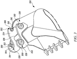
- the work tool 108 includes at least one engagement means, such as a first engagement means 226 and a second engagement means 228.
- the first engagement means 226 and the second engagement means 228 are adapted to aid in coupling the work tool 108 to the arm assembly 102.
- the first engagement means 226 and the second engagement means 228 are adapted to aid in coupling the work tool 108 to the first connecting means 222 and the second connecting means 224 of the arm assembly 102.
- the first engagement means 226 and the second engagement means 228 are formed on at least one plate, such as a first plate 232 and a second plate 234.
- the first plate 232 and the second plate 234 (also alternatively referred to as first side member 232 and the second side member 234, respectively) are separated by, and are connected to, a base member 236.
- the base member 236 may be adapted to attach the first plate 232 and the second plate 234 to the work tool 108, as illustrated in FIG. 3 .
- the base member 236 may be welded to the work tool 108.
- the first side member 232 and the second side member 234 may be formed as integral parts of the work tool 108.
- first side member 232 and the second side member 234 may be attached to the work tool 108 in various other ways, as would be known to a person skilled in the art, albeit with few variations to the structure of the first side member 232, the second side member 234, and the work tool 108.
- the at least one engagement means such as the first engagement means 226 and the second engagement means 228 includes at least one recess.
- the first engagement means 226 may include a first recess 300 in the form of a cut out on the at least one plate.
- the second engagement means 228 may include a second recess 302 in the form of a cut out on the at least one plate.
- at least one covering member such as a first covering member 308 and a second covering member 310 is adapted to abut against respective outer surfaces of the first side member 232 and the second side member 234 to partially cover the respective cut outs.
- a first aperture 304 extends from the first recess 300 and through the first covering member 308, and a second aperture 306 extends from the second recess 302 and through the second covering member 310.
- the first recess 300 includes a first neck portion 312 and a first receiving portion 314 connected to the first neck portion 312.
- the first neck portion 312 may be formed as a guiding portion with respect to the first receiving portion 314, as illustrated in FIG. 3 .
- the second recess 302 includes a second neck portion 316 and a second receiving portion 318 connected to the second neck portion 316.
- the second neck portion 316 may be formed as a guiding portion with respect to the second receiving portion 318, as illustrated.
- the first receiving portion 314 and the second receiving portion 318 may have a semi-circular profile.
- the first neck portion 312 and the first receiving portion 314 of the first recess 300 facilitate the coupling of the work tool 108 to the arm assembly 102. Further, the second neck portion 316 and the second receiving portion 318 of the second recess 302 also facilitate in coupling of the work tool 108 to the arm assembly 102. At least one of the first aperture 304 of the first recess 300 and the second aperture 306 of the second recess 302 facilitating locking of the work tool 108 to the arm assembly 102 upon engagement of the work tool 108 to the arm assembly 102.
- first receiving portion 314 of the first engagement means 226 and the second receiving portion 318 of the second engagement means 228 are directed towards a same direction, for example towards or opposite a direction of a material receiving opening of the work tool 108.
- first engagement means 226 and the second engagement means 228 are substantially identical in shape, size, and construction.
- the coupling apparatus 128 includes at least one coupling means, such as a first coupling means 320 and a second coupling means 322.
- the at least one coupling means is adapted to engage with the at least one, arm such as the first arm 106 or the second arm 216.
- the at least one coupling means may be adapted to engage with the at least one engagement means.
- the first coupling means 320 is adapted to engage with the second arm 216 through the second connecting means 224 of the arm assembly 102
- the second coupling means 322 is adapted to engage with the first arm 106 through the first connecting means 222 of the arm assembly 102.
- the coupling apparatus 128 can further include a frame 400, as shown in FIG. 5 and 6 .
- the frame 400 is adapted to be engaged with the first arm 106 and the second arm 216, and, upon engagement, prevent relative movement between the first arm 106 and the second arm 216.
- the frame 400 is engaged with the first connecting means 222 and the second connecting means 224 of the arm assembly 102.
- the frame 400 includes a first mounting means 402, a second mounting means 404, and at least one support, such as a support 406 and a support 408.
- the supports 406 and 408 may be in the form of a plate, connected between the first mounting means 402 and the second mounting means 404.
- first mounting means 402 is connected to the first connecting means 222 of the first arm 106 and the second mounting means 404 is connected to the second arm 216, the relative movement between the first arm 106 and the second arm 216 is prevented.
- the length of the support 406 is predetermined based on a distance between the first connecting means 222 and the second connecting means 224.
- the first mounting means 402 and the second mounting means 404 may be formed in any suitable shape and design so that to be engaged and coupled with the work tool 108 and the arm assembly 102.
- the first mounting means 402 and the second mounting means 404 may be shaped as bars or blocks or a combination thereof.
- the first coupling means 320 and the second coupling means 322 are provided as cylindrical protruding bodies on the supports 406 and 408, respectively.
- the first coupling means 320 and the second coupling means 322 are adapted to be engaged with the first engagement means 226 and the second engagement means 228, respectively. Therefore, the profile of the first coupling means 320 may be corresponding to the profile of the first neck portion 312 and the first receiving portion 314 of the first recess 300 of the first engagement means 226.
- the profile of the second coupling means 322 may be corresponding to the second neck portion 316 and the second receiving portion 318 of the second recess 302 of the second engagement means 228.
- the first coupling means 320 and the second coupling means 322 may have any other suitable shape and profile, such as spherical or cuboidal projections from the supports 406 and 408.
- the first coupling means 320 and the second coupling means 322 includes at least one pin.
- the at least one pin may be movable along an axis B-B' between its extended and retracted position.
- the first coupling means 320 includes at least one body 409 containing at least one pin, such as a first pin 410 and a second pin 412.
- the first pin 410 includes a first end portion 414, an elongated cylindrical body portion 416 extending from the first end portion 414 and a second end portion 418 opposite to the first end portion 414.
- the second pin 412 includes a first end portion 420, an elongated cylindrical body portion 422 extending from the first end portion 420 and a second end portion 424 opposite to the first end portion 420.
- the second end portion 424 of the second pin 412 is positioned towards the second end portion 418 of the first pin 410.
- the first end portion 414 of the first pin 410 and the first end portion 420 of the second pin 412 are positioned opposite to each other on opposite supports 406 and 408, respectively.
- the first pin 410 and second pin 412 have cylindrical profile and are adapted to slidably move with respect to each other along the axis B-B.' During such sliding movement, the first pin 410 and the second pin 412 may either move away form one another, or towards one another along the axis B-B.' Once the first pin 410 has moved substantially away from the second pin 412, it is referred to as the extended position of the coupling means, such as the first coupling means 320 (shown in FIG. 6 ). In the extended position, the first pin 410 and second pin 412 may engage with the second recess 302 of the second engagement means 228, to lock the work tool 108 with the arm assembly 102 (shown in FIG. 2 ).
- first pin 410 and the second pin 412 may slide out of the second recess 302 of the second engagement means 228, to unlock the work tool 108 from the arm assembly 102.
- such movement of the first pin member 410 and the second pin 412 is powered by pressurized hydraulic fluid which may be supplied to a space 426 defined by the second end portion 424 and the second end portion 418, therebetween.
- pressurized hydraulic fluid which may be supplied to a space 426 defined by the second end portion 424 and the second end portion 418, therebetween.
- such movement of the first pin member 410 and the second pin 412 may be powered by any other suitable means, such as pneumatic power source.
- a biasing means such as at least one spring, may be connected between the first and second pins 410, 412 to bias them towards the retracted position.
- FIG. 2 which illustrate the arm assembly 102 and the coupling apparatus 128 operably coupled to the arm assembly 102
- FIG. 3 which illustrates the work tool 108
- FIG. 5 which illustrates the frame 400
- the first coupling means 320 is also adapted to engage with the second engagement means 228, and the and the second coupling means 322 is adapted to engage with the first engagement means 226, of the work tool 108. Thereafter, movement of the first pin 410 and the second pin 412, to the extended position thereof, locks the first coupling means 320 with the second engagement means 228.
- the present disclosure provides the coupling apparatus 128 for assembling the work tool 108 with the arm assembly 102 of the machine 100.
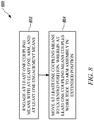
- the present disclosure further provides a method 800 for coupling the work tool 108 with the arm assembly 102.
- FIG. 8 shows a flowchart of the method 800, according to an embodiment of the present disclosure.
- the method 800 may be implemented in any suitable hardware, such that the hardware employed can perform the steps of the method 800 readily and on a real-time basis. For the convenience in description, various steps of the method 800 will be described in conjunction with the preceding figures of the present disclosure.
- the method 800 includes engaging the at least one coupling means 320, 322 with the at least one arm 106, 216 of the arm assembly 102.
- the arm assembly 102 may include the first connecting arm 204 and the second connecting arm 206 attached to the sides of the first arm 106 of the arm assembly 102.
- the coupling apparatus 128 may include the first connecting means 222 and the second connecting means 224 adapted to engage with the at least one arm 204, 208.
- the arm assembly 102 may include the first connecting means 222 and the second connecting means 224 adapted to receive the first mounting means 402 and the second mounting means 404 therein, respectively.
- the first coupling means 320 may be engaged with the second engagement means 228, and the second coupling means 322 may be engaged with the first engagement means 226.
- end portion of the second coupling means 322 may be inserted into the first recess 300 through the first neck portion 312 to the first receiving portion 314.
- the engagement of the second coupling means 322 with the first engagement means 226 is such that an angular movement of the work tool 108 with respect to the arm assembly 102 is allowed.
- end portion of the first coupling means 320 may be inserted into the second recess 302 through the second neck portion 316 to the second receiving portion 318.
- the method 800 includes moving at least one coupling means 320, 322, to an extended position, wherein the at least one coupling means 320, 322, couples the work tool 108 to the arm assembly 102 in the extended position.
- the first coupling means 320 includes the first pin 410 and the second pin 412. The first pin 410 and the second pin 412 may be moved away from each other, i.e. the first coupling means 320 may be moved to the extended position. In such an extended position of the first coupling means 320, the first end portion 414 of the first pin 410 and the first end portion 420 of the second pin 212 engage with the second aperture 306.
- the coupling apparatus 128 of the present disclosure provides an easy and efficient assembling of the work tool 108 to the arm assembly 102. Since the coupling or the assembling of the work tool 108 and the arm assembly 102 is assisted by a simple the first coupling means 320 having the first pin 210 and the second pin 212, the process of coupling can be performed in short duration of time. Further, owing to the presence of such coupling means having the first pin and the second pin, the coupling apparatus 128 can be replaced or coupled to the arm assembly 102 at any instant of time.
- first coupling means 320 since the coupling or the assembling of the work tool 108 and the arm assembly 102 may be carried out by first coupling means 320, overall weight and length of the arm assembly 102 remains substantially same, and therefore capabilities of the machine 100 remain uncompromised. Furthermore, the work tool 108 can be connected to the coupling apparatus 128 in two different orientations (i.e. the opening of the work tool 108 facing towards or away from the operator cabin 116) by virtue of the first and second engagement means 226, 228 being substantially identical.
Landscapes
- Engineering & Computer Science (AREA)
- Mechanical Engineering (AREA)
- Mining & Mineral Resources (AREA)
- Civil Engineering (AREA)
- General Engineering & Computer Science (AREA)
- Structural Engineering (AREA)
- Shovels (AREA)
- Automatic Assembly (AREA)
Claims (12)
- Vorrichtung (128) zum Koppeln eines Arbeitswerkzeugs (108) mit einer Armbaugruppe (102) einer Maschine (100), wobei die Armbaugruppe (102) einen ersten Arm (106) und einen zweiten Arm (206) umfasst und das Arbeitswerkzeug (108) mindestens ein Eingriffsmittel (226, 228) umfasst, wobei das mindestens eine Eingriffsmittel (226, 228) ein erstes Eingriffsmittel (226) mit mindestens einer Öffnung (304, 306) umfasst, wobei die Vorrichtung (128) umfasst:mindestens ein Kopplungsmittel (320, 322), das dafür ausgelegt ist, mit dem mindestens einen Arm (106, 206) und dem mindestens einen Eingriffsmittel (226, 228) in Eingriff zu treten,wobei das mindestens eine Kopplungsmittel (320, 322) dafür ausgelegt ist, sich zwischen einer ausgefahrenen Position zum Eingriff mit dem mindestens einen Eingriffsmittel (226, 228) zum Koppeln des Arbeitswerkzeugs (108) mit der Armbaugruppe (102) und einer eingefahrenen Position zum Lösen von dem mindestens einen Eingriffsmittel (226, 228) zum Trennen des Arbeitswerkzeugs (108) von der Armbaugruppe (102) zu bewegen; undeinen Rahmen (400), umfassend:ein erstes Anbringungsmittel (402) zum drehbaren Befestigen des Rahmens (400) an dem ersten Arm (106);ein zweites Anbringungsmittel (404) zum drehbaren Befestigen des Rahmens (400) an dem zweiten Arm (206); undmindestens einen Träger (406, 408) zum Verhindern einer relativen Bewegung zwischen dem ersten und zweiten Anbringungsmittel (402, 404),dadurch gekennzeichnet, dass das mindestens eine Kopplungsmittel (320, 322) ein erstes Kopplungsmittel (320) umfasst, das mindestens einen Stift (410, 412) umfasst, der entlang einer Achse zwischen der ausgefahrenen und der eingefahrenen Position beweglich ist, wobei die mindestens eine Öffnung (304, 306) konfiguriert ist, um den mindestens einen Stift (410, 412) aufzunehmen.
- Vorrichtung (128) nach Anspruch 1, wobei:das erste Kopplungsmittel (320) ferner mindestens einen Körper (209) und den mindestens einen Stift (410, 412), der aus dem mindestens einen Körper (209) ausfahrbar ist, umfasst; unddas erste Eingriffsmittel (226) mindestens eine Aussparung (300, 302) zum Aufnehmen des mindestens einen Körpers (209) umfasst und sich die mindestens eine Öffnung (304, 306) von der mindestens einen Aussparung (300, 302) zum Aufnehmen des mindestens einen Stifts (410, 412) erstreckt.
- Vorrichtung (128) nach Anspruch 1 oder Anspruch 2, wobei ein zweites Kopplungsmittel (322) mindestens einen Körper zum Aufnehmen in einer Aussparung (302) des zweiten Eingriffsmittels (228) umfasst.
- Vorrichtung (128) nach einem der Ansprüche 1 bis 3, wobei der mindestens eine Träger (406, 408) mindestens eine Platte (232, 234) umfasst und sich das mindestens eine Kopplungsmittel (320, 322) von der mindestens einen Platte (232, 234) erstreckt.
- Vorrichtung (128) nach einem der Ansprüche 1 bis 4, wobei die ersten Kopplungsmittel (320) koaxial mit den ersten Anbringungsmitteln (402) sind und die zweiten Kopplungsmittel (322) koaxial mit den zweiten Anbringungsmitteln (404) sind.
- Maschine (100) umfassend die Vorrichtung (128) nach einem der vorhergehenden Ansprüche.
- Maschine (100) nach Anspruch 6, umfassend das Arbeitswerkzeug (108), wobei jedes von dem ersten Eingriffsmittel (226) und zweiten Eingriffsmittel (228) eine Aussparung (302) und eine Öffnung (306) umfasst, die sich von der Aussparung (302) erstreckt.
- Maschinen (100) nach Anspruch 7, wobei die Aussparung umfasst:einen Halsabschnitt (312); undeinen Aufnahmeabschnitt (314), der mit dem Halsabschnitt (312) verbunden ist,wobei das mindestens eine Kopplungsmittel (320, 322) dafür ausgelegt ist, durch den Halsabschnitt (312) hindurch zu verlaufen und mit dem Aufnahmeabschnitt (314) in der ausgefahrenen Position in Eingriff zu treten.
- Maschine (100) nach Anspruch 7 oder Anspruch 8, wobei das Arbeitswerkzeug (108) mindestens eine Platte (232, 234) und mindestens ein Abdeckelement (308, 310) umfasst, wobei die mindestens eine Platte (232, 234) die Aussparung (300, 302) in Form eines Ausschnitts umfasst und das mindestens eine Abdeckelement (308, 310) den Ausschnitt abdeckt, wobei das mindestens eine Abdeckelement (308, 310) die Öffnung (304, 306) umfasst.
- Verfahren zum Koppeln eines Arbeitswerkzeugs (108) mit einer Armbaugruppe (102) einer Maschine (100), wobei die Armbaugruppe (102) einen ersten Arm (106) und einen zweiten Arm (206) umfasst und das Arbeitswerkzeug (108) mindestens ein Eingriffsmittel (226, 228) umfasst, wobei das mindestens eine Eingriffsmittel (226, 228) ein erstes Eingriffsmittel (226) umfasst, das mindestens eine Öffnung (304, 306) umfasst, wobei das Verfahren umfasst:Befestigen eines ersten Anbringungsmittels (402) eines Rahmens (400) an dem ersten Arm (106), wobei der Rahmen (400) relativ zu dem ersten Arm (106) drehbar ist;Befestigen eines zweiten Anbringungsmittels (404) des Rahmens (400) an dem zweiten Arm (206), wobei der Rahmen (400) relativ zu dem zweiten Arm (206) drehbar ist, und mindestens eines Trägers (406, 408) des Rahmens (400) zum Verhindern einer relativen Bewegung zwischen dem ersten und dem zweiten Anbringungsmittel (402, 404), wobei das mindestens eine Kopplungsmittel (320, 322) in dem ersten oder dem zweiten Anbringungsmittel (402, 404) positioniert wird;Ineingriffbringen mindestens eines Kopplungsmittels (320, 322) mit dem mindestens einen Arm (106, 206) und dem mindestens einen Eingriffsmittel (226, 228), wobei das mindestens eine Kopplungsmittel (320, 322) ein erstes Kopplungsmittel (320) umfasst, das mindestens einen Stift (410, 412) umfasst, der entlang einer Achse zwischen der ausgefahrenen und der eingefahrenen Position beweglich ist, wobei die mindestens eine Öffnung (304, 306) konfiguriert ist, um den mindestens einen Stift (410, 412) aufzunehmen; undDrehen des mindestens einen Stifts (410, 412) in eine ausgefahrene Position, wobei der mindestens eine Stift (410, 412) das Arbeitswerkzeug (108) in der ausgefahrenen Position mit der Armbaugruppe (102) koppelt.
- Verfahren nach Anspruch 10, wobei der Schritt des Ineingriffbringens des mindestens einen Kopplungsmittels (320, 322) mit dem mindestens einen Eingriffsmittel (226, 228) das Einführen des mindestens einen Kopplungsmittels (320, 322) durch einen Halsabschnitt (312) in einen Aufnahmeabschnitt (314) umfasst, wenn sich das mindestens eine Kopplungsmittel (320, 322) in einer eingefahrenen Position befindet.
- Verfahren nach Anspruch 11, wobei das mindestens eine Kopplungsmittel (320, 322) in der ausgefahrenen Position mit einer Öffnung am Aufnahmeabschnitt (314) in Eingriff steht.
Applications Claiming Priority (1)
| Application Number | Priority Date | Filing Date | Title |
|---|---|---|---|
| GB1520732.7A GB2544746A (en) | 2015-11-24 | 2015-11-24 | Apparatus and method for assembling work tool to a machine |
Publications (2)
| Publication Number | Publication Date |
|---|---|
| EP3176331A1 EP3176331A1 (de) | 2017-06-07 |
| EP3176331B1 true EP3176331B1 (de) | 2021-08-11 |
Family
ID=55133300
Family Applications (1)
| Application Number | Title | Priority Date | Filing Date |
|---|---|---|---|
| EP16199591.5A Active EP3176331B1 (de) | 2015-11-24 | 2016-11-18 | Vorrichtung und verfahren zur montage eines arbeitswerkzeugs an eine maschine |
Country Status (4)
| Country | Link |
|---|---|
| US (1) | US10190283B2 (de) |
| EP (1) | EP3176331B1 (de) |
| CN (1) | CN106759576B (de) |
| GB (1) | GB2544746A (de) |
Families Citing this family (7)
| Publication number | Priority date | Publication date | Assignee | Title |
|---|---|---|---|---|
| GB2574215B (en) * | 2018-05-30 | 2020-11-11 | Caterpillar Work Tools Bv | Coupling assembly for attaching a tool to a hydraulic excavator or other work machine |
| CN109235518B (zh) * | 2018-09-25 | 2024-01-12 | 中铁工程机械研究设计院有限公司 | 工程机械工具头快换结构及机臂 |
| US10801178B2 (en) | 2018-12-07 | 2020-10-13 | Deere & Company | Work tool attachment for a work machine |
| US10760243B2 (en) | 2018-12-07 | 2020-09-01 | Deere & Company | Work tool attachment for a work machine |
| US11208785B2 (en) * | 2018-12-12 | 2021-12-28 | Caterpillar Inc. | Tool coupling arrangement having zero offset |
| CN111456125A (zh) * | 2020-04-13 | 2020-07-28 | 柳州柳工挖掘机有限公司 | 挖掘机工作装置及挖掘机 |
| CN111456126B (zh) * | 2020-04-23 | 2022-04-01 | 三一重机有限公司 | 一种挖掘机调试专用工装及挖掘机 |
Family Cites Families (28)
| Publication number | Priority date | Publication date | Assignee | Title |
|---|---|---|---|---|
| GB8500911D0 (en) | 1985-01-15 | 1985-02-20 | Mason S T | Quick-change fitting |
| DE4109783C2 (de) | 1990-03-23 | 1998-04-09 | Hilton S Enterprises Inc Pty L | Schnellkuppelvorrichtung für ein Gerät zur Durchführung von Erdbewegungen |
| DE4010224C2 (de) * | 1990-03-30 | 1994-05-19 | Porsche Ag | Schnellwechselvorrichtung |
| US5597283A (en) | 1991-04-09 | 1997-01-28 | Jones; Gordon | Quick coupling for heavy equipment attachment |
| US5400531A (en) | 1992-08-20 | 1995-03-28 | Brown; Hilton T. | Excavator device |
| US5546683A (en) * | 1993-09-29 | 1996-08-20 | Clark; George J. | Bucket attachment device with remote controlled retractable pins |
| US5692855A (en) * | 1994-06-21 | 1997-12-02 | Farmers' Factory Co. | Automatic quick-connect coupler for implements |
| KR100202087B1 (ko) * | 1995-12-30 | 1999-06-15 | 토니헬샴 | 중장비의 어태치먼트 착탈장치 |
| WO2001004425A1 (en) | 1999-07-12 | 2001-01-18 | Jrb Company, Inc. | Excavator arm assembly with integral quick coupler |
| IT1314744B1 (it) * | 2000-05-19 | 2003-01-03 | Lameter S R L | Dispositivo di attacco rapido di attrezzi per escavatori. |
| KR100430064B1 (ko) * | 2001-05-18 | 2004-05-03 | 한국기계연구원 | 굴삭기용 퀵 커플러 |
| JP2005504198A (ja) * | 2001-09-26 | 2005-02-10 | ハンウー ティーエヌシー コーポレーション | 重機用アタッチメントカップリング装置 |
| US6658770B2 (en) * | 2002-01-11 | 2003-12-09 | Rockland, Inc. | Implement coupling assembly for excavating machines and the like |
| US6857842B2 (en) * | 2002-01-17 | 2005-02-22 | Rockland, Inc. | Adapter assembly for an implement coupling system |
| US20040245002A1 (en) | 2003-06-06 | 2004-12-09 | Shingo Muroto | Screw-rod locking structure for attachment fixture |
| JP2007009606A (ja) | 2005-07-01 | 2007-01-18 | Muroto Tekkosho:Kk | パワーショベルのアタッチメント取付具の安全装置 |
| US20070201973A1 (en) | 2006-02-28 | 2007-08-30 | Woods Equipment Company | Quick coupler system |
| US7690880B2 (en) * | 2006-04-25 | 2010-04-06 | Clark Equipment Company | Locking device for hydraulic attachment interface |
| US8020324B2 (en) * | 2006-10-19 | 2011-09-20 | Caterpillar Inc. | Spacing assembly for pin grabber implements |
| NZ550869A (en) * | 2006-10-26 | 2008-11-28 | J B Sales Internat Ltd | A coupler with latch for twin pin digger bucket |
| ES2304330B1 (es) * | 2008-04-21 | 2009-08-06 | Javier Aracama Martinez De Lahidalga | Sistema de enganche de brazo de excavadora. |
| IT1392648B1 (it) * | 2009-01-23 | 2012-03-16 | Malacrino | Dispositivo di attacco rapido, particolarmente per macchine operatrici |
| US8469623B2 (en) | 2009-04-01 | 2013-06-25 | Caterpillar Work Tools B.V. | Quick coupling device |
| CA2815032C (en) * | 2013-04-30 | 2017-05-09 | Ami Attachments Inc. | Coupler-assembly for attaching bucket or the like to articulating arm |
| ITBO20130357A1 (it) | 2013-07-10 | 2015-01-11 | Cangini Benne Srl | Attacco rapido, e relativa apparecchiatura di connessione, di un utensile ad un braccio di azionamento |
| GB2522420B (en) | 2014-01-22 | 2018-09-05 | Caterpillar Work Tools Bv | Exchange system for implement of machine |
| GB2522454B (en) | 2014-01-24 | 2017-02-22 | Caterpillar Work Tools Bv | Positioning system for implement of machine |
| GB2544744A (en) * | 2015-11-24 | 2017-05-31 | Caterpillar Work Tools Bv | Apparatus and method for coupling work tool to a machine |
-
2015
- 2015-11-24 GB GB1520732.7A patent/GB2544746A/en not_active Withdrawn
-
2016
- 2016-11-15 US US15/352,174 patent/US10190283B2/en active Active
- 2016-11-18 CN CN201611028824.5A patent/CN106759576B/zh active Active
- 2016-11-18 EP EP16199591.5A patent/EP3176331B1/de active Active
Non-Patent Citations (1)
| Title |
|---|
| None * |
Also Published As
| Publication number | Publication date |
|---|---|
| US10190283B2 (en) | 2019-01-29 |
| US20170145654A1 (en) | 2017-05-25 |
| EP3176331A1 (de) | 2017-06-07 |
| GB2544746A (en) | 2017-05-31 |
| CN106759576B (zh) | 2021-07-16 |
| CN106759576A (zh) | 2017-05-31 |
| GB201520732D0 (en) | 2016-01-06 |
Similar Documents
| Publication | Publication Date | Title |
|---|---|---|
| EP3176331B1 (de) | Vorrichtung und verfahren zur montage eines arbeitswerkzeugs an eine maschine | |
| JP7389878B2 (ja) | 土木機器に固設された地面係合摩耗部品のためのハンドリングシステム | |
| EP1954887B1 (de) | Kompaktbaggerarbeitsgerätschnittstelle | |
| US20140317967A1 (en) | Excavator with Expanded Work Implement Compatibility | |
| EP3241949B1 (de) | Integrierte schnellkupplung für baggerbolzengreifer | |
| US9404236B2 (en) | Thumb assembly having a stop | |
| US9903095B2 (en) | Tool coupler | |
| EP3173535B1 (de) | Vorrichtung und verfahren zur kopplung eines arbeitswerkzeugs mit einer maschine | |
| EP3173534B1 (de) | Vorrichtung und verfahren zur kopplung eines arbeitswerkzeugs mit einer maschine | |
| EP3894637B1 (de) | Werkzeugkupplungsanordnung mit nullpunktverschiebung | |
| US20160251820A1 (en) | Work tool assembly and coupler | |
| US20150176241A1 (en) | Combination excavating bucket having a retractable tooth arm | |
| WO2004016863A1 (en) | A connector | |
| US20140230587A1 (en) | Thumb Assembly | |
| US10815100B1 (en) | Grappling assembly for use with utility equipment | |
| EP2662500A1 (de) | Verriegelbare Verlängerung für Arbeitswerkzeug | |
| CN223738634U (zh) | 属具双锁快换连接器、工程机械臂及工程机械 | |
| US20170130419A1 (en) | Latch assembly for service pin of machine | |
| JP2006097348A (ja) | 作業具装着装置 | |
| JPH04124324A (ja) | 建設機械の付属品着脱機構 |
Legal Events
| Date | Code | Title | Description |
|---|---|---|---|
| 17P | Request for examination filed |
Effective date: 20161118 |
|
| AK | Designated contracting states |
Kind code of ref document: A1 Designated state(s): AL AT BE BG CH CY CZ DE DK EE ES FI FR GB GR HR HU IE IS IT LI LT LU LV MC MK MT NL NO PL PT RO RS SE SI SK SM TR |
|
| AX | Request for extension of the european patent |
Extension state: BA ME |
|
| PUAI | Public reference made under article 153(3) epc to a published international application that has entered the european phase |
Free format text: ORIGINAL CODE: 0009012 |
|
| STAA | Information on the status of an ep patent application or granted ep patent |
Free format text: STATUS: REQUEST FOR EXAMINATION WAS MADE |
|
| STAA | Information on the status of an ep patent application or granted ep patent |
Free format text: STATUS: EXAMINATION IS IN PROGRESS |
|
| 17Q | First examination report despatched |
Effective date: 20190730 |
|
| GRAP | Despatch of communication of intention to grant a patent |
Free format text: ORIGINAL CODE: EPIDOSNIGR1 |
|
| STAA | Information on the status of an ep patent application or granted ep patent |
Free format text: STATUS: GRANT OF PATENT IS INTENDED |
|
| INTG | Intention to grant announced |
Effective date: 20210310 |
|
| GRAS | Grant fee paid |
Free format text: ORIGINAL CODE: EPIDOSNIGR3 |
|
| GRAA | (expected) grant |
Free format text: ORIGINAL CODE: 0009210 |
|
| STAA | Information on the status of an ep patent application or granted ep patent |
Free format text: STATUS: THE PATENT HAS BEEN GRANTED |
|
| AK | Designated contracting states |
Kind code of ref document: B1 Designated state(s): AL AT BE BG CH CY CZ DE DK EE ES FI FR GB GR HR HU IE IS IT LI LT LU LV MC MK MT NL NO PL PT RO RS SE SI SK SM TR |
|
| REG | Reference to a national code |
Ref country code: CH Ref legal event code: EP |
|
| REG | Reference to a national code |
Ref country code: DE Ref legal event code: R096 Ref document number: 602016061917 Country of ref document: DE |
|
| REG | Reference to a national code |
Ref country code: IE Ref legal event code: FG4D Ref country code: AT Ref legal event code: REF Ref document number: 1419517 Country of ref document: AT Kind code of ref document: T Effective date: 20210915 |
|
| REG | Reference to a national code |
Ref country code: SE Ref legal event code: TRGR |
|
| REG | Reference to a national code |
Ref country code: NL Ref legal event code: FP |
|
| REG | Reference to a national code |
Ref country code: LT Ref legal event code: MG9D |
|
| REG | Reference to a national code |
Ref country code: AT Ref legal event code: MK05 Ref document number: 1419517 Country of ref document: AT Kind code of ref document: T Effective date: 20210811 |
|
| REG | Reference to a national code |
Ref country code: NO Ref legal event code: T2 Effective date: 20210811 |
|
| PG25 | Lapsed in a contracting state [announced via postgrant information from national office to epo] |
Ref country code: HR Free format text: LAPSE BECAUSE OF FAILURE TO SUBMIT A TRANSLATION OF THE DESCRIPTION OR TO PAY THE FEE WITHIN THE PRESCRIBED TIME-LIMIT Effective date: 20210811 Ref country code: RS Free format text: LAPSE BECAUSE OF FAILURE TO SUBMIT A TRANSLATION OF THE DESCRIPTION OR TO PAY THE FEE WITHIN THE PRESCRIBED TIME-LIMIT Effective date: 20210811 Ref country code: AT Free format text: LAPSE BECAUSE OF FAILURE TO SUBMIT A TRANSLATION OF THE DESCRIPTION OR TO PAY THE FEE WITHIN THE PRESCRIBED TIME-LIMIT Effective date: 20210811 Ref country code: BG Free format text: LAPSE BECAUSE OF FAILURE TO SUBMIT A TRANSLATION OF THE DESCRIPTION OR TO PAY THE FEE WITHIN THE PRESCRIBED TIME-LIMIT Effective date: 20211111 Ref country code: LT Free format text: LAPSE BECAUSE OF FAILURE TO SUBMIT A TRANSLATION OF THE DESCRIPTION OR TO PAY THE FEE WITHIN THE PRESCRIBED TIME-LIMIT Effective date: 20210811 Ref country code: PT Free format text: LAPSE BECAUSE OF FAILURE TO SUBMIT A TRANSLATION OF THE DESCRIPTION OR TO PAY THE FEE WITHIN THE PRESCRIBED TIME-LIMIT Effective date: 20211213 Ref country code: ES Free format text: LAPSE BECAUSE OF FAILURE TO SUBMIT A TRANSLATION OF THE DESCRIPTION OR TO PAY THE FEE WITHIN THE PRESCRIBED TIME-LIMIT Effective date: 20210811 Ref country code: FI Free format text: LAPSE BECAUSE OF FAILURE TO SUBMIT A TRANSLATION OF THE DESCRIPTION OR TO PAY THE FEE WITHIN THE PRESCRIBED TIME-LIMIT Effective date: 20210811 |
|
| PG25 | Lapsed in a contracting state [announced via postgrant information from national office to epo] |
Ref country code: PL Free format text: LAPSE BECAUSE OF FAILURE TO SUBMIT A TRANSLATION OF THE DESCRIPTION OR TO PAY THE FEE WITHIN THE PRESCRIBED TIME-LIMIT Effective date: 20210811 Ref country code: LV Free format text: LAPSE BECAUSE OF FAILURE TO SUBMIT A TRANSLATION OF THE DESCRIPTION OR TO PAY THE FEE WITHIN THE PRESCRIBED TIME-LIMIT Effective date: 20210811 Ref country code: GR Free format text: LAPSE BECAUSE OF FAILURE TO SUBMIT A TRANSLATION OF THE DESCRIPTION OR TO PAY THE FEE WITHIN THE PRESCRIBED TIME-LIMIT Effective date: 20211112 |
|
| PG25 | Lapsed in a contracting state [announced via postgrant information from national office to epo] |
Ref country code: DK Free format text: LAPSE BECAUSE OF FAILURE TO SUBMIT A TRANSLATION OF THE DESCRIPTION OR TO PAY THE FEE WITHIN THE PRESCRIBED TIME-LIMIT Effective date: 20210811 |
|
| REG | Reference to a national code |
Ref country code: DE Ref legal event code: R097 Ref document number: 602016061917 Country of ref document: DE |
|
| PG25 | Lapsed in a contracting state [announced via postgrant information from national office to epo] |
Ref country code: SM Free format text: LAPSE BECAUSE OF FAILURE TO SUBMIT A TRANSLATION OF THE DESCRIPTION OR TO PAY THE FEE WITHIN THE PRESCRIBED TIME-LIMIT Effective date: 20210811 Ref country code: SK Free format text: LAPSE BECAUSE OF FAILURE TO SUBMIT A TRANSLATION OF THE DESCRIPTION OR TO PAY THE FEE WITHIN THE PRESCRIBED TIME-LIMIT Effective date: 20210811 Ref country code: RO Free format text: LAPSE BECAUSE OF FAILURE TO SUBMIT A TRANSLATION OF THE DESCRIPTION OR TO PAY THE FEE WITHIN THE PRESCRIBED TIME-LIMIT Effective date: 20210811 Ref country code: EE Free format text: LAPSE BECAUSE OF FAILURE TO SUBMIT A TRANSLATION OF THE DESCRIPTION OR TO PAY THE FEE WITHIN THE PRESCRIBED TIME-LIMIT Effective date: 20210811 Ref country code: CZ Free format text: LAPSE BECAUSE OF FAILURE TO SUBMIT A TRANSLATION OF THE DESCRIPTION OR TO PAY THE FEE WITHIN THE PRESCRIBED TIME-LIMIT Effective date: 20210811 Ref country code: AL Free format text: LAPSE BECAUSE OF FAILURE TO SUBMIT A TRANSLATION OF THE DESCRIPTION OR TO PAY THE FEE WITHIN THE PRESCRIBED TIME-LIMIT Effective date: 20210811 |
|
| PLBE | No opposition filed within time limit |
Free format text: ORIGINAL CODE: 0009261 |
|
| STAA | Information on the status of an ep patent application or granted ep patent |
Free format text: STATUS: NO OPPOSITION FILED WITHIN TIME LIMIT |
|
| PG25 | Lapsed in a contracting state [announced via postgrant information from national office to epo] |
Ref country code: MC Free format text: LAPSE BECAUSE OF FAILURE TO SUBMIT A TRANSLATION OF THE DESCRIPTION OR TO PAY THE FEE WITHIN THE PRESCRIBED TIME-LIMIT Effective date: 20210811 |
|
| REG | Reference to a national code |
Ref country code: CH Ref legal event code: PL |
|
| 26N | No opposition filed |
Effective date: 20220512 |
|
| PG25 | Lapsed in a contracting state [announced via postgrant information from national office to epo] |
Ref country code: LU Free format text: LAPSE BECAUSE OF NON-PAYMENT OF DUE FEES Effective date: 20211118 Ref country code: IT Free format text: LAPSE BECAUSE OF FAILURE TO SUBMIT A TRANSLATION OF THE DESCRIPTION OR TO PAY THE FEE WITHIN THE PRESCRIBED TIME-LIMIT Effective date: 20210811 Ref country code: BE Free format text: LAPSE BECAUSE OF NON-PAYMENT OF DUE FEES Effective date: 20211130 |
|
| REG | Reference to a national code |
Ref country code: BE Ref legal event code: MM Effective date: 20211130 |
|
| PG25 | Lapsed in a contracting state [announced via postgrant information from national office to epo] |
Ref country code: SI Free format text: LAPSE BECAUSE OF FAILURE TO SUBMIT A TRANSLATION OF THE DESCRIPTION OR TO PAY THE FEE WITHIN THE PRESCRIBED TIME-LIMIT Effective date: 20210811 Ref country code: LI Free format text: LAPSE BECAUSE OF NON-PAYMENT OF DUE FEES Effective date: 20211130 Ref country code: CH Free format text: LAPSE BECAUSE OF NON-PAYMENT OF DUE FEES Effective date: 20211130 |
|
| PG25 | Lapsed in a contracting state [announced via postgrant information from national office to epo] |
Ref country code: IE Free format text: LAPSE BECAUSE OF NON-PAYMENT OF DUE FEES Effective date: 20211118 |
|
| PG25 | Lapsed in a contracting state [announced via postgrant information from national office to epo] |
Ref country code: FR Free format text: LAPSE BECAUSE OF NON-PAYMENT OF DUE FEES Effective date: 20211130 |
|
| PG25 | Lapsed in a contracting state [announced via postgrant information from national office to epo] |
Ref country code: HU Free format text: LAPSE BECAUSE OF FAILURE TO SUBMIT A TRANSLATION OF THE DESCRIPTION OR TO PAY THE FEE WITHIN THE PRESCRIBED TIME-LIMIT; INVALID AB INITIO Effective date: 20161118 |
|
| P01 | Opt-out of the competence of the unified patent court (upc) registered |
Effective date: 20230517 |
|
| PG25 | Lapsed in a contracting state [announced via postgrant information from national office to epo] |
Ref country code: CY Free format text: LAPSE BECAUSE OF FAILURE TO SUBMIT A TRANSLATION OF THE DESCRIPTION OR TO PAY THE FEE WITHIN THE PRESCRIBED TIME-LIMIT Effective date: 20210811 |
|
| PG25 | Lapsed in a contracting state [announced via postgrant information from national office to epo] |
Ref country code: MK Free format text: LAPSE BECAUSE OF FAILURE TO SUBMIT A TRANSLATION OF THE DESCRIPTION OR TO PAY THE FEE WITHIN THE PRESCRIBED TIME-LIMIT Effective date: 20210811 |
|
| PG25 | Lapsed in a contracting state [announced via postgrant information from national office to epo] |
Ref country code: TR Free format text: LAPSE BECAUSE OF FAILURE TO SUBMIT A TRANSLATION OF THE DESCRIPTION OR TO PAY THE FEE WITHIN THE PRESCRIBED TIME-LIMIT Effective date: 20210811 |
|
| PG25 | Lapsed in a contracting state [announced via postgrant information from national office to epo] |
Ref country code: MT Free format text: LAPSE BECAUSE OF FAILURE TO SUBMIT A TRANSLATION OF THE DESCRIPTION OR TO PAY THE FEE WITHIN THE PRESCRIBED TIME-LIMIT Effective date: 20210811 |
|
| PGFP | Annual fee paid to national office [announced via postgrant information from national office to epo] |
Ref country code: NL Payment date: 20251022 Year of fee payment: 10 |
|
| PGFP | Annual fee paid to national office [announced via postgrant information from national office to epo] |
Ref country code: DE Payment date: 20251022 Year of fee payment: 10 |
|
| PGFP | Annual fee paid to national office [announced via postgrant information from national office to epo] |
Ref country code: GB Payment date: 20251022 Year of fee payment: 10 |
|
| PGFP | Annual fee paid to national office [announced via postgrant information from national office to epo] |
Ref country code: NO Payment date: 20251024 Year of fee payment: 10 |
|
| PGFP | Annual fee paid to national office [announced via postgrant information from national office to epo] |
Ref country code: SE Payment date: 20251022 Year of fee payment: 10 |