EP3176121A1 - An elevator car arrangement and method for dampening vibrations - Google Patents
An elevator car arrangement and method for dampening vibrations Download PDFInfo
- Publication number
- EP3176121A1 EP3176121A1 EP15197530.7A EP15197530A EP3176121A1 EP 3176121 A1 EP3176121 A1 EP 3176121A1 EP 15197530 A EP15197530 A EP 15197530A EP 3176121 A1 EP3176121 A1 EP 3176121A1
- Authority
- EP
- European Patent Office
- Prior art keywords
- elevator car
- rod
- plate
- sling
- car body
- Prior art date
- Legal status (The legal status is an assumption and is not a legal conclusion. Google has not performed a legal analysis and makes no representation as to the accuracy of the status listed.)
- Granted
Links
Images



Classifications
-
- B—PERFORMING OPERATIONS; TRANSPORTING
- B66—HOISTING; LIFTING; HAULING
- B66B—ELEVATORS; ESCALATORS OR MOVING WALKWAYS
- B66B11/00—Main component parts of lifts in, or associated with, buildings or other structures
- B66B11/02—Cages, i.e. cars
- B66B11/026—Attenuation system for shocks, vibrations, imbalance, e.g. passengers on the same side
- B66B11/0266—Passive systems
- B66B11/0273—Passive systems acting between car and supporting frame
-
- B—PERFORMING OPERATIONS; TRANSPORTING
- B66—HOISTING; LIFTING; HAULING
- B66B—ELEVATORS; ESCALATORS OR MOVING WALKWAYS
- B66B19/00—Mining-hoist operation
- B66B19/007—Mining-hoist operation method for modernisation of elevators
-
- F—MECHANICAL ENGINEERING; LIGHTING; HEATING; WEAPONS; BLASTING
- F16—ENGINEERING ELEMENTS AND UNITS; GENERAL MEASURES FOR PRODUCING AND MAINTAINING EFFECTIVE FUNCTIONING OF MACHINES OR INSTALLATIONS; THERMAL INSULATION IN GENERAL
- F16F—SPRINGS; SHOCK-ABSORBERS; MEANS FOR DAMPING VIBRATION
- F16F15/00—Suppression of vibrations in systems; Means or arrangements for avoiding or reducing out-of-balance forces, e.g. due to motion
- F16F15/02—Suppression of vibrations of non-rotating, e.g. reciprocating systems; Suppression of vibrations of rotating systems by use of members not moving with the rotating systems
- F16F15/04—Suppression of vibrations of non-rotating, e.g. reciprocating systems; Suppression of vibrations of rotating systems by use of members not moving with the rotating systems using elastic means
- F16F15/08—Suppression of vibrations of non-rotating, e.g. reciprocating systems; Suppression of vibrations of rotating systems by use of members not moving with the rotating systems using elastic means with rubber springs ; with springs made of rubber and metal
Definitions
- the invention relates to an isolation of an elevator car, in particular to an arrangement for isolating elevator car from vibrations coming from guide rails for improving ride comfort of an elevator.
- the invention relates in particularly to an elevator car arrangement comprising an elevator car body and an elevator car sling according to the preamble of the independent claim 1.
- the invention further relates to a method for dampening vibrations according to the preamble of the independent claim 11.
- the elevator car body is generally fitted inside an elevator car sling, which the elevator car sling is suspended by hoisting roping and fitted to travel along guide rails.
- the guide rails are formed by connecting successive guide rail members together such that joints are formed in the assembled guide rails.
- Base isolation is a well-known principle in the construction industry and is usually used to protect buildings against earthquake. Sometimes it is even used in server rooms to protect computer equipment against earthquake.
- the principle is to use a relatively low frequency base so that ground movement has very little effect on the movement of the building.
- this cannot be used as such in elevators because as a difference between elevators and buildings, buildings are not coupled at the top to the ground which is the case with elevators in which the elevator car body is fixed to the elevator car sling at the top of the elevator car body, and thus it is coupled to the rail also at the top.
- An object of the present invention is to provide an elevator car arrangement and a method for dampening vibrations so as to overcome the above problems.
- the objects of the invention are achieved by an arrangement and a method which are characterized by what is stated in the independent claims.
- the preferred embodiments of the invention are disclosed in the dependent claims.
- the invention is based on the idea of providing a base isolation type of a protection for an elevator car for reducing vibrations caused by guide rails to the elevator car body.
- the elevator car arrangement comprises a hanging damper arranged to connect the elevator car body and the elevator car sling together for dampening vibrations coming from guide rails through the elevator car sling to the elevator car body.
- the hanging damper is a pendulum that keeps the car as straight as possible, keeps the frequency low and prevents most resonances coming to the elevator car body.
- an elevator car arrangement comprises an elevator car body and an elevator car sling and further a hanging damper arranged to connect the elevator car body and the elevator car sling together for dampening vibrations coming from guide rails through the elevator car sling to the elevator car body.
- the hanging damper comprises a first part connected to a bottom part of the elevator car body; a second part connected to the elevator car sling; and a damping element arranged to dampen vibrations coming from the second part to the first part.
- the first part comprises a first rod and a first plate connected together, said first rod having a first end connected to the bottom part of the elevator car body and a second end connected to the first plate.
- the second part comprises a second plate and at least one second rod in connection with the second plate.
- the damping element is arranged between the first plate of the first part and the second plate of the second part such that the damping element has a connection with the first plate of the first part and the second plate of the second part such that the connection between the first part and the second part is arranged through the damping element.
- the method for dampening vibrations coming from guide rails through the elevator car sling to the elevator car body comprises the steps of providing a hanging damper comprising a first part and a second part between the elevator car body and the elevator car sling by connecting the first part to a bottom part of the elevator car body, said first part comprising a first rod and a first plate connected together, said first rod having a first end to be connected to the bottom part of the elevator car body and a second end connected to the first plate; connecting the second part to the elevator car sling, said second part comprising a second plate and at least one second rod in connection with the second plate, said second rod having a first end and a second end; arranging a damping element between the first plate of the first part and the second plate of the second part to have a connection with the first plate of the first part and the second plate of the second part to dampen vibrations coming from the second part to the first part; and connecting the first part and the second part together through the damping element.
- Ride comfort of the elevator car means that there is not much vibrations or noise that comes from the interface between the elevator car body and the elevator car sling.
- a better isolated elevator car means that the excitations coming from guide rail misalignments, ropes vibrations, dynamic unbalance due to variable compensating and travelling cables are not transmitted to a floor or to a roof of the elevator car body.
- An advantage that an interface between the elevator car body and the elevator car sling comprises also at least one damping element is that the vibrations of the elevator car due to wind loads, i.e. turbulences due to protuberances in the car outer surface; big changes in the clearance between the elevator car and the shaft when passing landing doors or counterweight, have smaller amplitude and die faster.
- An advantage is that an elevator car body and an elevator car sling interface having a damping element decreases the lateral vibrations and also the structure borne noise.
- An advantage of the invention is that the hanging damper is easy to install by connecting it between a beam of an elevator car body and a beam of an elevator car sling in which it is also easy to maintain without a need for disassembling the elevator car body or the elevator car sling. Also there is a possibility to add and/or remove additional mass to the hanging damper without disassembling the car body or the sling. There is also no danger destroying the elevator if the additional mass accidentally falls because the additional mass is not fixed on top of the elevator car or to the walls of the elevator car.
- Figure 1 shows a profile an elevator car arrangement according to the invention in which the elevator car arrangement comprises an elevator car body 2 and an elevator car sling 3.
- the elevator car arrangement further comprises a hanging damper 1 arranged to connect the elevator car body 2 and the elevator car sling 3 together for dampening vibrations coming from guide rails through the elevator car sling 3 to the elevator car body 2.
- the hanging damper 1 is especially arranged to connect the lower part of the elevator car body 2 to the elevator car sling 3.
- the elevator car arrangement comprises four hanging dampers 1, two arranged on both sides of the elevator car, i.e. two on each side of the elevator car body 2.
- the figure 1 is a side view of the elevator car arrangement it only shows two hanging dampers 1 when the two other hanging dampers 1 are arranged on the other side of the elevator car.
- Figure 1 shows the hanging damper 1 in a simplified form in which the hanging damper comprises a first part 11 connected to a bottom part of the elevator car body 2 and a second part 12 connected to the elevator car sling 3. More accurately the first part 11 is connected to a beam 21 of an elevator car body 2 and the second part is connected to a beam 31 of an elevator car sling 3.
- Figure 2 shows an embodiment of a hanging damper 1 of the elevator car arrangement according to the invention as seen from a side of the elevator car.
- the hanging damper 1 shown in figure 1 is a detail from figure 1 .
- the hanging damper 1 is arranged to connect the elevator car body 2 and the elevator car sling 3 together for dampening vibrations coming from guide rails through the elevator car sling 3 to the elevator car body 2.
- the hanging damper 1 comprises a first part 11 connected to a bottom part of the elevator car body 2, a second part 12 connected to the elevator car sling 3 and a damping element 13 arranged to dampen vibrations coming from the second part 12 to the first part 11.
- the hanging damper 1 can be seen in detail in figure 4 which is an exploded view of the hanging damper shown in figure 2 .
- the first part 11 comprises a first rod 11a and a first plate 11b connected together, said first rod 11a having a first end 11a1 connected to the bottom part of the elevator car body 2 and a second end 11a2 connected to the first plate 11b.
- the second part 12 comprises a second plate 12a and at least one second rod 12b in connection with the second plate 12a. As shown in the figures 2 and 3 the second part 12 comprises in this embodiment two second rods 12b.
- the damping element 13 is arranged between the first plate 11b of the first part 11 and the second plate 12a of the second part 12 such that the damping element 11 has a connection with the first plate 11b of the first part 11 and the second plate 12a of the second part 12 such that the connection between the first part 11 and the second part 12 is arranged through the damping element 13.
- the hanging damper 1 is connected to the bottom part of the elevator car such that the first rod 11a is connected to a beam 21 of the elevator car body 2 and the second rod 12b is having a connection with a beam 31 of the elevator car sling 3.
- the connection between the first rod 11a and the elevator car body 2 is a threaded connection.
- the second rod 12b is arranged to go through the first plate 11b and the damping element 13 to have a connection with the second plate 12a.
- the first plate 11b and the damping element 13 are provided with a hole for the second rod 12b to go through.
- the hole in the first plate 11b is preferably large enough in diameter so that the second rod 12b does not touch the first plate 11b.
- the connection between the second rod 12b and the beam 31 of the elevator car sling 3 is a thread nut fixing in connection with the beam 31.
- the thread nut fixing is preferably arranged such that there is at least one baseplate 12c between the nut 12e and the beam 31.
- the baseplate 12c can be such that it is common for at least two second rods 12b and is arranged to extend around the first rod 11a such that the baseplate 12c has a hole for the first rod 11a and holes for the at least two second rods 12b or in another embodiment the second rods 12b may have separate baseplates 12c in which case the baseplate does not extend to the area of the first rod 11a.
- a rubber bushing 12f or a bushing 12f of some other elastic material is preferably provided between the second rod 12b and the beam 31 such that the second rod 12b and the beam 31 are not in a direct connection together.
- the first rod 11a is arranged to go through the beam 31 of the elevator car sling 3 without having a connection with the sling 3.
- the damping element 11 preferably comprises rubber or polyurethane or some other suitable material.
- the hanging damper 1 may comprise a post for an additional mass to be added to the elevator car arrangement. This is advantageous when needing to balance the elevator car body 2 easily.
- the additional mass can be added for example through a magnetic connection on the first plate 11b.
- the first part 11 comprises a first rod 11a and a first plate 11b connected together, said first rod 11a having a first end 11a1 to be connected to the bottom part of the elevator car body 2 and a second end 11a2 connected to the first plate 11b and the second part 12 comprises a second plate 12a and at least one second rod 12b in connection with the second plate 12a, said second rod 12b having a first end 12b1 and a second end 12b2.
- the method comprises the steps of providing a hanging damper 1 comprising a first part 11 and a second part 12 between the elevator car body 2 and the elevator car sling 3 by connecting the first part 11 to a bottom part of the elevator car body 2, connecting the second part 12 to the elevator car sling 3, arranging a damping element 11 between the first plate 11b of the first part 11 and the second plate 12a of the second part 12 to have a connection with the first plate 11b of the first part 11 and the second plate 12a of the second part 12 to dampen vibrations coming from the second part 12 to the first part 11; and connecting the first part 11 and the second part 12 together through the damping element 11.
- the step of connecting the first part 11 to a bottom part of the elevator car body 2 comprises the steps of arranging the first rod 11a to go through a beam 31 of the elevator car sling 3 and connecting the first end 11a1 of the first rod 11a to a beam 21 of the elevator car body 2.
- the step of connecting the second part 12 to the elevator car sling 3 comprises the steps of arranging the at least one second rod 12b through a hole in a beam 31 of the elevator car sling 3 such that the first end 12b1 and the second end 12b2 are on different sides of the beam 31 or on different sides of part of the beam 31; providing a nut 12d to the first end 12b1 of the second rod 12b and tightening the nut 12d.
- the step of connecting the second part 12 to the elevator car sling 3 may further comprise a step of arranging a baseplate 12c on the elevator car sling 3 to the side of the elevator car body 2 such that the second rod 12b goes through a hole in the baseplate 12c, i.e. arranging a baseplate 12c between the beam 31 and the nut 12d.
- the step of arranging a damping element 11 between the first plate 11b of the first part 11 and the second plate 12a of the second part 12 comprises the steps of providing a hole in the damping element 11 for the at least one second rod 12b to go through the damping element 11; arranging the damping element 11 in connection with the first plate 11b such that the second rod 12b goes through the damping element 11; arranging the second plate 12a in connection with the damping element 11, said second plate 12a having a hole for the second rod 12b to go through the second plate 12a; and tightening a nut 12d to the second end 12b2 of the second rod 12b.
- the method further comprises a step of adding mass to the hanging damper 1 for balancing the elevator car body 2.
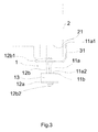
- Figure 3 shows the hanging damper 1 as seen from the front side of the elevator car.
- the elevator car comprising the elevator car body 2 and the elevator car sling 3 together with corresponding beams is simplified and only parts that are meaningful for the hanging damper 1 and its connections are shown in the figure.
- the elevator car body 2 comprises a beam 21 in which the first end 11a1 of the first rod 11a of the hanging damper 1 is connected.
- the connection is preferably a threaded connection.
- the connection between the first end 11a1 of the first rod 11a and the elevator car body 2 is the only connection between the hanging damper 1 and the elevator car body 2.
- the first rod 11a is arranged to go through the beam 31 of the elevator car sling 3 shown in the figure.
- the beam 31 of the elevator car sling 3 comprises a hole having a size that is large enough for the first rod 11a not having a contact with the elevator car sling 3 in a rest position.
- the rest position is when the elevator is not moving in a vertical direction.
- the first rod 11a may have a narrowed section in the area that is provided in the hole of the beam 31.
- the beam of the elevator car sling 3 comprises hole having a diameter that is larger than the diameter of the first rod 11a.
- the second end 11a2 of the first rod 11a is connected to the first plate 11b.
- the connection between the first rod 11a and the first plate 11b is preferably a threaded connection. So the first part 11 of the hanging damper comprises a first rod 11a and a first plate 11b connected together preferably through a threaded connection.
- the connection between the first rod 11a and the first plate 11b is a welded connection.
- the hanging damper 1 also comprises the second part 12 which comprises a second plate 12a and at least one second rod 12b in connection with the second plate 12a.
- the second rod 12b goes through the beam 31 of the elevator car sling 3 such that a first end 12b1 of the second rod 12b and a second end 12b2 of the second rod 12b are on different sides of the beam 31.
- the second rod 12b is arranged in connection with the elevator car sling 3 through a thread nut fixing so that the second rod 12b preferably has a threaded portion in the end of the second rod 12b.
- the second rod 12b is also arranged in connection with the second plate 12a through a thread nut fixing similarly as described in connection with the beam 31 of the elevator car sling 3. So the second rod 12b preferably comprises a threaded portion in both ends of the second rod 12b or the whole second rod 12b is threaded.
- the second rod 12b goes through the first plate 11b which has a hole larger than the second rod 12b.
- the second rod 12b also goes through the damping element 13 arranged between the first plate 11b and the second plate 12a.
- the connection between the second rod 12b and the second plate 12a may be arranged through welding or some other way.
- the damping element 13 is arranged between the first plate 11b and the second plate 12a such that by tightening the nut in the first end 12b1 and/or in the second end 12b2 of the second rod 12b the contact between the damping element 13 and the first plate 11b and the second plate 12a can be made tight.
- the first part 11 is connected to the elevator car body 2 and the second part 12 is connected to the elevator car sling 3 and the damping element 13 connects the first part 11 and the second part 12 together such that it is the only connection between the lower part of the elevator car body and the elevator car sling.
- the first rod 11a is connected from its first end 11a1 to the elevator car body 2 and especially to its beam 21 and from its second end 11a2 to the first plate 11b.
- the second rod 12b is connected from its first end 12b1 to the elevator car sling 3 and especially to its beam 31 and from its second end 12b2 to the second plate 12a.
- the first plate 11b and the second plate 12a are isolated from each other through the damping element 13.
- the damping element 13 is rubber and/or polyurethane. So the direct connection between the elevator car body 2 and the elevator car sling 3 is replaced by the connection between the first plate 11b and the second plate 12a through the damping element 13.
- the damping element 13 ensures that the vibrations from the elevator car sling 3 excited by guide rail misalignments, roller, counterweight passing bye, ropes or something else is not transferred straight to the elevator car body and to passengers in it.
- the damping element 13 in other words attenuates or kill the vibrations.
- the elevator car sling 3 has a beam 31 to which the second rod 12b of the hanging damper 1 is connected.
- the beam 31 has the beam 31 therefore at least two holes from which one is for the first rod 11a and is larger than the first rod 11a so that there is no direct connection with the first rod 11a and the beam 31.
- the second rod 12b also comprises a soft rubber covering 12e between the nut 12d and the second plate 12a and/or between the nut 12d and a baseplate 12c which is preferably arranged between the nut 12d and the beam 31 of the elevator car sling 3.
- the baseplate 12c is part of the second part 12 of the hanging damper 1.
- Mass can be added on each hanging damper 1 in order to balance the elevator car if it is tilted due to heavier doors, top guard or decoration panels.
- the additional mass is can be placed on top of the first plate 11b for example with clamps or with magnet.
- An elevator comprises an elevator car body 2 and an elevator car sling 3 and a hanging damper 1.
Landscapes
- Engineering & Computer Science (AREA)
- Mechanical Engineering (AREA)
- Physics & Mathematics (AREA)
- General Engineering & Computer Science (AREA)
- Fluid Mechanics (AREA)
- Civil Engineering (AREA)
- Structural Engineering (AREA)
- Chemical & Material Sciences (AREA)
- Acoustics & Sound (AREA)
- Aviation & Aerospace Engineering (AREA)
- Combustion & Propulsion (AREA)
- Cage And Drive Apparatuses For Elevators (AREA)
- Lift-Guide Devices, And Elevator Ropes And Cables (AREA)
Abstract
Description
- The invention relates to an isolation of an elevator car, in particular to an arrangement for isolating elevator car from vibrations coming from guide rails for improving ride comfort of an elevator. The invention relates in particularly to an elevator car arrangement comprising an elevator car body and an elevator car sling according to the preamble of the
independent claim 1. The invention further relates to a method for dampening vibrations according to the preamble of theindependent claim 11. - Usually in elevators the elevator car body is generally fitted inside an elevator car sling, which the elevator car sling is suspended by hoisting roping and fitted to travel along guide rails. The guide rails are formed by connecting successive guide rail members together such that joints are formed in the assembled guide rails. These joints and possible impreciseness in guide rail alignment causes vibrations to the elevator car body via the elevator car sling connected to the elevator car body. This means that ride comfort in the elevator suffers and noise increases, which is especially the case with high speed elevators. Ride comfort for high speed elevators is very much influenced by the interface between the elevator car and the sling.
- Base isolation is a well-known principle in the construction industry and is usually used to protect buildings against earthquake. Sometimes it is even used in server rooms to protect computer equipment against earthquake. The principle is to use a relatively low frequency base so that ground movement has very little effect on the movement of the building. However this cannot be used as such in elevators because as a difference between elevators and buildings, buildings are not coupled at the top to the ground which is the case with elevators in which the elevator car body is fixed to the elevator car sling at the top of the elevator car body, and thus it is coupled to the rail also at the top.
- In prior art depending on the load of the elevator car several springs are used for isolating the floor of an elevator car body from the elevator car sling. The top of the elevator car has to be additionally supported because a top fixing limits the movement of the elevator car in case of emergency braking and also it is needed for supporting the tilted elevator car due to doors, toe guard and inner decoration.
- An object of the present invention is to provide an elevator car arrangement and a method for dampening vibrations so as to overcome the above problems. The objects of the invention are achieved by an arrangement and a method which are characterized by what is stated in the independent claims. The preferred embodiments of the invention are disclosed in the dependent claims.
- The invention is based on the idea of providing a base isolation type of a protection for an elevator car for reducing vibrations caused by guide rails to the elevator car body. According to the invention the elevator car arrangement comprises a hanging damper arranged to connect the elevator car body and the elevator car sling together for dampening vibrations coming from guide rails through the elevator car sling to the elevator car body. The hanging damper is a pendulum that keeps the car as straight as possible, keeps the frequency low and prevents most resonances coming to the elevator car body.
- According to the invention an elevator car arrangement comprises an elevator car body and an elevator car sling and further a hanging damper arranged to connect the elevator car body and the elevator car sling together for dampening vibrations coming from guide rails through the elevator car sling to the elevator car body. The hanging damper comprises a first part connected to a bottom part of the elevator car body; a second part connected to the elevator car sling; and a damping element arranged to dampen vibrations coming from the second part to the first part. The first part comprises a first rod and a first plate connected together, said first rod having a first end connected to the bottom part of the elevator car body and a second end connected to the first plate. The second part comprises a second plate and at least one second rod in connection with the second plate. The damping element is arranged between the first plate of the first part and the second plate of the second part such that the damping element has a connection with the first plate of the first part and the second plate of the second part such that the connection between the first part and the second part is arranged through the damping element.
- According to the invention the method for dampening vibrations coming from guide rails through the elevator car sling to the elevator car body comprises the steps of providing a hanging damper comprising a first part and a second part between the elevator car body and the elevator car sling by connecting the first part to a bottom part of the elevator car body, said first part comprising a first rod and a first plate connected together, said first rod having a first end to be connected to the bottom part of the elevator car body and a second end connected to the first plate; connecting the second part to the elevator car sling, said second part comprising a second plate and at least one second rod in connection with the second plate, said second rod having a first end and a second end; arranging a damping element between the first plate of the first part and the second plate of the second part to have a connection with the first plate of the first part and the second plate of the second part to dampen vibrations coming from the second part to the first part; and connecting the first part and the second part together through the damping element.
- Ride comfort of the elevator car means that there is not much vibrations or noise that comes from the interface between the elevator car body and the elevator car sling. A better isolated elevator car means that the excitations coming from guide rail misalignments, ropes vibrations, dynamic unbalance due to variable compensating and travelling cables are not transmitted to a floor or to a roof of the elevator car body. An advantage that an interface between the elevator car body and the elevator car sling comprises also at least one damping element is that the vibrations of the elevator car due to wind loads, i.e. turbulences due to protuberances in the car outer surface; big changes in the clearance between the elevator car and the shaft when passing landing doors or counterweight, have smaller amplitude and die faster. An advantage is that an elevator car body and an elevator car sling interface having a damping element decreases the lateral vibrations and also the structure borne noise.
- An advantage of the invention is that the hanging damper is easy to install by connecting it between a beam of an elevator car body and a beam of an elevator car sling in which it is also easy to maintain without a need for disassembling the elevator car body or the elevator car sling. Also there is a possibility to add and/or remove additional mass to the hanging damper without disassembling the car body or the sling. There is also no danger destroying the elevator if the additional mass accidentally falls because the additional mass is not fixed on top of the elevator car or to the walls of the elevator car.
- In the following the invention will be described in greater detail by means of preferred embodiments with reference to the attached drawings, in which
-
Figure 1 shows a profile an elevator car arrangement according to the invention shown from side of the elevator; -
Figure 2 shows an embodiment of a hanging damper of the elevator car arrangement according to the invention from the same perspective asfigure 1 ; -
Figure 3 shows an embodiment of a hanging damper from the front side of the elevator; and -
Figure 4 shows an exploded view of the hanging damper shown infigure 2 . -
Figure 1 shows a profile an elevator car arrangement according to the invention in which the elevator car arrangement comprises anelevator car body 2 and anelevator car sling 3. The elevator car arrangement further comprises a hangingdamper 1 arranged to connect theelevator car body 2 and the elevator car sling 3 together for dampening vibrations coming from guide rails through theelevator car sling 3 to theelevator car body 2. The hangingdamper 1 is especially arranged to connect the lower part of theelevator car body 2 to theelevator car sling 3. In a preferred embodiment of the invention the elevator car arrangement comprises four hangingdampers 1, two arranged on both sides of the elevator car, i.e. two on each side of theelevator car body 2. As thefigure 1 is a side view of the elevator car arrangement it only shows two hangingdampers 1 when the two other hangingdampers 1 are arranged on the other side of the elevator car. -
Figure 1 shows the hangingdamper 1 in a simplified form in which the hanging damper comprises afirst part 11 connected to a bottom part of theelevator car body 2 and asecond part 12 connected to theelevator car sling 3. More accurately thefirst part 11 is connected to abeam 21 of anelevator car body 2 and the second part is connected to abeam 31 of anelevator car sling 3. -
Figure 2 shows an embodiment of a hangingdamper 1 of the elevator car arrangement according to the invention as seen from a side of the elevator car. In other words the hangingdamper 1 shown infigure 1 is a detail fromfigure 1 . The hangingdamper 1 is arranged to connect theelevator car body 2 and the elevator car sling 3 together for dampening vibrations coming from guide rails through the elevator car sling 3 to theelevator car body 2. Thehanging damper 1 comprises afirst part 11 connected to a bottom part of theelevator car body 2, asecond part 12 connected to theelevator car sling 3 and adamping element 13 arranged to dampen vibrations coming from thesecond part 12 to thefirst part 11. The hangingdamper 1 can be seen in detail infigure 4 which is an exploded view of the hanging damper shown infigure 2 . Thefirst part 11 comprises afirst rod 11a and afirst plate 11b connected together, saidfirst rod 11a having a first end 11a1 connected to the bottom part of theelevator car body 2 and a second end 11a2 connected to thefirst plate 11b. Thesecond part 12 comprises asecond plate 12a and at least onesecond rod 12b in connection with thesecond plate 12a. As shown in thefigures 2 and3 thesecond part 12 comprises in this embodiment twosecond rods 12b. Thedamping element 13 is arranged between thefirst plate 11b of thefirst part 11 and thesecond plate 12a of thesecond part 12 such that thedamping element 11 has a connection with thefirst plate 11b of thefirst part 11 and thesecond plate 12a of thesecond part 12 such that the connection between thefirst part 11 and thesecond part 12 is arranged through thedamping element 13. The hangingdamper 1 is connected to the bottom part of the elevator car such that thefirst rod 11a is connected to abeam 21 of theelevator car body 2 and thesecond rod 12b is having a connection with abeam 31 of theelevator car sling 3. In a preferred embodiment of the invention the connection between thefirst rod 11a and theelevator car body 2 is a threaded connection. - As shown in
figure 2 thesecond rod 12b is arranged to go through thefirst plate 11b and thedamping element 13 to have a connection with thesecond plate 12a. This means that thefirst plate 11b and thedamping element 13 are provided with a hole for thesecond rod 12b to go through. The hole in thefirst plate 11b is preferably large enough in diameter so that thesecond rod 12b does not touch thefirst plate 11b. As further can be seen fromfigure 2 the connection between thesecond rod 12b and thebeam 31 of theelevator car sling 3 is a thread nut fixing in connection with thebeam 31. The thread nut fixing is preferably arranged such that there is at least onebaseplate 12c between thenut 12e and thebeam 31. Thebaseplate 12c can be such that it is common for at least twosecond rods 12b and is arranged to extend around thefirst rod 11a such that thebaseplate 12c has a hole for thefirst rod 11a and holes for the at least twosecond rods 12b or in another embodiment thesecond rods 12b may haveseparate baseplates 12c in which case the baseplate does not extend to the area of thefirst rod 11a. Arubber bushing 12f or abushing 12f of some other elastic material is preferably provided between thesecond rod 12b and thebeam 31 such that thesecond rod 12b and thebeam 31 are not in a direct connection together. Thefirst rod 11a is arranged to go through thebeam 31 of theelevator car sling 3 without having a connection with thesling 3. This means that there is a hole in thebeam 31 of theelevator car sling 3 which is large enough in diameter so that thefirst rod 11a does not touch thebeam 31 or thefirst rod 11a may have a narrowing section in the area of the hole where thefirst rod 11a goes through thebeam 31. The dampingelement 11 preferably comprises rubber or polyurethane or some other suitable material. - The hanging
damper 1 may comprise a post for an additional mass to be added to the elevator car arrangement. This is advantageous when needing to balance theelevator car body 2 easily. The additional mass can be added for example through a magnetic connection on thefirst plate 11b. - The
first part 11 comprises afirst rod 11a and afirst plate 11b connected together, saidfirst rod 11a having a first end 11a1 to be connected to the bottom part of theelevator car body 2 and a second end 11a2 connected to thefirst plate 11b and thesecond part 12 comprises asecond plate 12a and at least onesecond rod 12b in connection with thesecond plate 12a, saidsecond rod 12b having a first end 12b1 and a second end 12b2. - In the method according to the invention the method comprises the steps of providing a hanging
damper 1 comprising afirst part 11 and asecond part 12 between theelevator car body 2 and theelevator car sling 3 by connecting thefirst part 11 to a bottom part of theelevator car body 2, connecting thesecond part 12 to theelevator car sling 3, arranging a dampingelement 11 between thefirst plate 11b of thefirst part 11 and thesecond plate 12a of thesecond part 12 to have a connection with thefirst plate 11b of thefirst part 11 and thesecond plate 12a of thesecond part 12 to dampen vibrations coming from thesecond part 12 to thefirst part 11; and connecting thefirst part 11 and thesecond part 12 together through the dampingelement 11. - The step of connecting the
first part 11 to a bottom part of theelevator car body 2 comprises the steps of arranging thefirst rod 11a to go through abeam 31 of theelevator car sling 3 and connecting the first end 11a1 of thefirst rod 11a to abeam 21 of theelevator car body 2. - The step of connecting the
second part 12 to theelevator car sling 3 comprises the steps of arranging the at least onesecond rod 12b through a hole in abeam 31 of theelevator car sling 3 such that the first end 12b1 and the second end 12b2 are on different sides of thebeam 31 or on different sides of part of thebeam 31; providing anut 12d to the first end 12b1 of thesecond rod 12b and tightening thenut 12d. The step of connecting thesecond part 12 to theelevator car sling 3 may further comprise a step of arranging abaseplate 12c on theelevator car sling 3 to the side of theelevator car body 2 such that thesecond rod 12b goes through a hole in thebaseplate 12c, i.e. arranging abaseplate 12c between thebeam 31 and thenut 12d. - The step of arranging a damping
element 11 between thefirst plate 11b of thefirst part 11 and thesecond plate 12a of thesecond part 12 comprises the steps of providing a hole in the dampingelement 11 for the at least onesecond rod 12b to go through the dampingelement 11; arranging the dampingelement 11 in connection with thefirst plate 11b such that thesecond rod 12b goes through the dampingelement 11; arranging thesecond plate 12a in connection with the dampingelement 11, saidsecond plate 12a having a hole for thesecond rod 12b to go through thesecond plate 12a; and tightening anut 12d to the second end 12b2 of thesecond rod 12b. - The method further comprises a step of adding mass to the hanging
damper 1 for balancing theelevator car body 2. -
Figure 3 shows the hangingdamper 1 as seen from the front side of the elevator car. The elevator car comprising theelevator car body 2 and theelevator car sling 3 together with corresponding beams is simplified and only parts that are meaningful for the hangingdamper 1 and its connections are shown in the figure. Theelevator car body 2 comprises abeam 21 in which the first end 11a1 of thefirst rod 11a of the hangingdamper 1 is connected. The connection is preferably a threaded connection. The connection between the first end 11a1 of thefirst rod 11a and theelevator car body 2 is the only connection between the hangingdamper 1 and theelevator car body 2. Thefirst rod 11a is arranged to go through thebeam 31 of theelevator car sling 3 shown in the figure. This is arranged such that thebeam 31 of theelevator car sling 3 comprises a hole having a size that is large enough for thefirst rod 11a not having a contact with theelevator car sling 3 in a rest position. The rest position is when the elevator is not moving in a vertical direction. Thefirst rod 11a may have a narrowed section in the area that is provided in the hole of thebeam 31. In other words the beam of theelevator car sling 3 comprises hole having a diameter that is larger than the diameter of thefirst rod 11a. The second end 11a2 of thefirst rod 11a is connected to thefirst plate 11b. The connection between thefirst rod 11a and thefirst plate 11b is preferably a threaded connection. So thefirst part 11 of the hanging damper comprises afirst rod 11a and afirst plate 11b connected together preferably through a threaded connection. In another embodiment of the invention the connection between thefirst rod 11a and thefirst plate 11b is a welded connection. - The hanging
damper 1 also comprises thesecond part 12 which comprises asecond plate 12a and at least onesecond rod 12b in connection with thesecond plate 12a. As can be seen fromfigure 3 thesecond rod 12b goes through thebeam 31 of theelevator car sling 3 such that a first end 12b1 of thesecond rod 12b and a second end 12b2 of thesecond rod 12b are on different sides of thebeam 31. Thesecond rod 12b is arranged in connection with theelevator car sling 3 through a thread nut fixing so that thesecond rod 12b preferably has a threaded portion in the end of thesecond rod 12b. In this embodiment thesecond rod 12b is also arranged in connection with thesecond plate 12a through a thread nut fixing similarly as described in connection with thebeam 31 of theelevator car sling 3. So thesecond rod 12b preferably comprises a threaded portion in both ends of thesecond rod 12b or the wholesecond rod 12b is threaded. Thesecond rod 12b goes through thefirst plate 11b which has a hole larger than thesecond rod 12b. Thesecond rod 12b also goes through the dampingelement 13 arranged between thefirst plate 11b and thesecond plate 12a. As thesecond rod 12b is arranged in connection with thesecond plate 12a through a thread nut fixing it means that thesecond rod 12b goes through thesecond plate 12a as well. In another embodiment of the invention the connection between thesecond rod 12b and thesecond plate 12a may be arranged through welding or some other way. - The damping
element 13 is arranged between thefirst plate 11b and thesecond plate 12a such that by tightening the nut in the first end 12b1 and/or in the second end 12b2 of thesecond rod 12b the contact between the dampingelement 13 and thefirst plate 11b and thesecond plate 12a can be made tight. - So the
first part 11 is connected to theelevator car body 2 and thesecond part 12 is connected to theelevator car sling 3 and the dampingelement 13 connects thefirst part 11 and thesecond part 12 together such that it is the only connection between the lower part of the elevator car body and the elevator car sling. In other words thefirst rod 11a is connected from its first end 11a1 to theelevator car body 2 and especially to itsbeam 21 and from its second end 11a2 to thefirst plate 11b. Thesecond rod 12b is connected from its first end 12b1 to theelevator car sling 3 and especially to itsbeam 31 and from its second end 12b2 to thesecond plate 12a. Thefirst plate 11b and thesecond plate 12a are isolated from each other through the dampingelement 13. So thefirst plate 11b and thesecond plate 12a are not connected to each other directly but through the dampingelement 13. The dampingelement 13 is rubber and/or polyurethane. So the direct connection between theelevator car body 2 and theelevator car sling 3 is replaced by the connection between thefirst plate 11b and thesecond plate 12a through the dampingelement 13. The dampingelement 13 ensures that the vibrations from theelevator car sling 3 excited by guide rail misalignments, roller, counterweight passing bye, ropes or something else is not transferred straight to the elevator car body and to passengers in it. The dampingelement 13 in other words attenuates or kill the vibrations. - The
elevator car sling 3 has abeam 31 to which thesecond rod 12b of the hangingdamper 1 is connected. As thefirst rod 11a of thefirst part 11 goes through thebeam 31 has thebeam 31 therefore at least two holes from which one is for thefirst rod 11a and is larger than thefirst rod 11a so that there is no direct connection with thefirst rod 11a and thebeam 31. Preferably there is a covering, a bushing or a padding between thefirst rod 11a and thebeam 31 around the area of the hole in the case that thefirst rod 11a and thebeam 31 of theelevator car sling 3 accidentally touch during the elevator run in abnormal conditions. - The
second rod 12b also comprises a soft rubber covering 12e between thenut 12d and thesecond plate 12a and/or between thenut 12d and abaseplate 12c which is preferably arranged between thenut 12d and thebeam 31 of theelevator car sling 3. Thebaseplate 12c is part of thesecond part 12 of the hangingdamper 1. - Mass can be added on each hanging
damper 1 in order to balance the elevator car if it is tilted due to heavier doors, top guard or decoration panels. The additional mass is can be placed on top of thefirst plate 11b for example with clamps or with magnet. - An elevator comprises an
elevator car body 2 and anelevator car sling 3 and a hangingdamper 1. - It will be obvious to a person skilled in the art that, as the technology advances, the inventive concept can be implemented in various ways. The invention and its embodiments are not limited to the examples described above but may vary within the scope of the claims.
Claims (16)
- An elevator car arrangement comprising an elevator car body (2) and an elevator car sling (3), characterized in that the elevator car arrangement further comprising a hanging damper (1) arranged to connect the elevator car body (2) and the elevator car sling (3) together for dampening vibrations coming from guide rails through the elevator car sling (3) to the elevator car body (2), the hanging damper (1) comprises
a first part (11) connected to a bottom part of the elevator car body (2);
a second part (12) connected to the elevator car sling (3); and
a damping element (13) arranged to dampen vibrations coming from the second part (12) to the first part (11),
the first part (11) comprises a first rod (11a) and a first plate (11b) connected together, said first rod (11a) having a first end (11a1) connected to the bottom part of the elevator car body (2) and a second end (11a2) connected to the first plate (11b);
the second part (12) comprises a second plate (12a) and at least one second rod (12b) in connection with the second plate (12a);
the damping element (11) is arranged between the first plate (11b) of the first part (11) and the second plate (12a) of the second part (12) such that the damping element (11) has a connection with the first plate (11b) of the first part (11) and the second plate (12a) of the second part (12) such that the connection between the first part (11) and the second part (12) is arranged through the damping element (11). - An elevator car arrangement according to claim 1, characterized in that the hanging damper (1) is connected to the bottom part of the elevator car such that the first rod (11a) is connected to a beam of the elevator car body (2) and the second rod (12b) is having a connection with a beam of the elevator car sling (3).
- An elevator car arrangement according to claim 1 or 2, characterized in that the connection between the first rod (11a) and the elevator car body (2) is a threaded connection.
- An elevator car arrangement according to any of preceding claims, characterized in that the second rod (12b) is arranged to go through the first plate (11b) and the damping element (13) to have a connection with the second plate (12a).
- An elevator car arrangement according to any of preceding claims, characterized in that the connection between the second rod (12b) and the beam of the elevator car sling (3) is a thread nut fixing in connection with the beam.
- An elevator car arrangement according to any of preceding claims, characterized in that the first rod (11a) is arranged to go through the beam of the elevator car sling (3) without having a connection with the sling (3).
- An elevator car arrangement according to any of preceding claims, characterized in that the arrangement comprises four hanging dampers (1), two on each side of the elevator car body (2).
- An elevator car arrangement according to any of preceding claims, characterized in that the damping element (11) comprises rubber.
- An elevator car arrangement according to any of preceding claims, characterized in that the damping element (11) comprises polyurethane.
- An elevator car arrangement according to any of preceding claims, characterized in that the hanging damper (1) comprises a post for an additional mass to be added to the elevator car arrangement.
- Method for dampening vibrations coming from guide rails through the elevator car sling (3) to the elevator car body (2), characterized in that the method comprising the steps of:providing a hanging damper (1) comprising a first part (11) and a second part (12) between the elevator car body (2) and the elevator car sling (3) byconnecting the first part (11) to a bottom part of the elevator car body (2), said first part (11) comprising a first rod (11a) and a first plate (11b) connected together, said first rod (11a) having a first end (11a1) to be connected to the bottom part of the elevator car body (2) and a second end (11a2) connected to the first plate (11b);connecting the second part (12) to the elevator car sling (3), said second part (12) comprising a second plate (12a) and at least one second rod (12b) in connection with the second plate (12a), said second rod (12b) having a first end (12b1) and a second end (12b2);arranging a damping element (11) between the first plate (11b) of the first part (11) and the second plate (12a) of the second part (12) to have a connection with the first plate (11b) of the first part (11) and the second plate (12a) of the second part (12) to dampen vibrations coming from the second part (12) to the first part (11); andconnecting the first part (11) and the second part (12) together through the damping element (11).
- Method according to claim 11, characterized in that the step of connecting the first part (11) to a bottom part of the elevator car body (2) comprises the steps of
arranging the first rod (11a) to go through a beam (31) of the elevator car sling (3) and
connecting the first end (11a1) of the first rod (11a) to a beam (21) of the elevator car body (2). - Method according to claim 11, characterized in that the step of connecting the second part (12) to the elevator car sling (3) comprises the steps of
arranging the at least one second rod (12b) through a hole in a beam (31) of the elevator car sling (3) such that the first end (12b1) of the second rod (12b) and the second end (12b2) of the second rod (12b) are on different sides of the beam (31) or on different sides of part of the beam (31);
providing a nut (12d) to the first end (12b1) of the second rod (12b) and tightening the nut (12d). - Method according to claim 11, characterized in that the step of arranging a damping element (11) between the first plate (11b) of the first part (11) and the second plate (12a) of the second part (12) comprises the steps of
providing a hole in the damping element (11) for the at least one second rod (12b) to go through the damping element (11);
arranging the damping element (11) in connection with the first plate (11b) such that the second rod (12b) goes through the damping element (11);
arranging the second plate (12a) in connection with the damping element (11), said second plate (12a) having a hole for the second rod (12b) to go through the second plate (12a); and
tightening a nut (12d) to the second end (12b2) of the second rod (12b). - Method according to claim 11, characterized in that the method further comprises a step of adding mass to the hanging damper (1) for balancing the elevator car body (2).
- An elevator comprising an elevator car arrangement according to claim 1.
Priority Applications (3)
| Application Number | Priority Date | Filing Date | Title |
|---|---|---|---|
| EP15197530.7A EP3176121B1 (en) | 2015-12-02 | 2015-12-02 | An elevator car arrangement and method for dampening vibrations |
| US15/357,546 US10464784B2 (en) | 2015-12-02 | 2016-11-21 | Elevator car arrangement and method for dampening vibrations |
| CN201611093811.6A CN106829698B (en) | 2015-12-02 | 2016-12-01 | Elevator car apparatus and method for suppressing vibration |
Applications Claiming Priority (1)
| Application Number | Priority Date | Filing Date | Title |
|---|---|---|---|
| EP15197530.7A EP3176121B1 (en) | 2015-12-02 | 2015-12-02 | An elevator car arrangement and method for dampening vibrations |
Publications (2)
| Publication Number | Publication Date |
|---|---|
| EP3176121A1 true EP3176121A1 (en) | 2017-06-07 |
| EP3176121B1 EP3176121B1 (en) | 2018-08-08 |
Family
ID=54771008
Family Applications (1)
| Application Number | Title | Priority Date | Filing Date |
|---|---|---|---|
| EP15197530.7A Active EP3176121B1 (en) | 2015-12-02 | 2015-12-02 | An elevator car arrangement and method for dampening vibrations |
Country Status (3)
| Country | Link |
|---|---|
| US (1) | US10464784B2 (en) |
| EP (1) | EP3176121B1 (en) |
| CN (1) | CN106829698B (en) |
Families Citing this family (6)
| Publication number | Priority date | Publication date | Assignee | Title |
|---|---|---|---|---|
| ES2426590T3 (en) * | 2008-06-17 | 2013-10-24 | Otis Elevator Company | Configuration of a suspended elevator box |
| WO2021220408A1 (en) * | 2020-04-28 | 2021-11-04 | 三菱電機株式会社 | Vibration damping device for elevator |
| CN112693994B (en) * | 2020-12-22 | 2021-09-17 | 亚洲富士电梯股份有限公司 | Modular structure additional elevator and manufacturing equipment and manufacturing process thereof |
| AU2023343630A1 (en) | 2022-09-15 | 2025-03-13 | Inventio Ag | Elevator car assembly for a double-deck elevator |
| EP4477595A1 (en) | 2023-06-13 | 2024-12-18 | Inventio Ag | Elevator car system for an elevator system, elevator system and method for compensating vibrations of an elevator car arrangement of an elevator system |
| CN120992383B (en) * | 2025-10-23 | 2026-02-10 | 中建三局集团西北有限公司 | Elevator well baffle impact test frame |
Citations (3)
| Publication number | Priority date | Publication date | Assignee | Title |
|---|---|---|---|---|
| GB1407158A (en) * | 1972-12-01 | 1975-09-24 | Hitachi Ltd | Elevator device |
| JPS5110768U (en) * | 1974-07-12 | 1976-01-26 | ||
| US5325937A (en) * | 1993-05-13 | 1994-07-05 | Otis Elevator Company | Elevator platform isolation |
Family Cites Families (20)
| Publication number | Priority date | Publication date | Assignee | Title |
|---|---|---|---|---|
| US1380125A (en) * | 1920-10-11 | 1921-05-31 | Kansas City Elevator Mfg Compa | Tension-equalizing and shock-absorbing device |
| US2147660A (en) * | 1936-12-05 | 1939-02-21 | Julian S Loewus | Vibration dampener |
| CH426147A (en) * | 1965-04-07 | 1966-12-15 | Inventio Ag | Guide device for a housing of an elevator car that is movably supported in a suspension frame |
| FR1536431A (en) * | 1967-07-06 | 1968-08-16 | Extendable frame for the suspension of an elevator car | |
| CH476623A (en) * | 1968-12-06 | 1969-08-15 | Inventio Ag | Elevator car |
| US4428460A (en) * | 1979-10-15 | 1984-01-31 | Elevators Pty. Limited | Lift car suspension |
| FI76769C (en) * | 1986-12-31 | 1988-12-12 | Kone Oy | Way to attach a lift basket to a grip frame |
| JPH0699849A (en) * | 1992-09-18 | 1994-04-12 | Nissan Motor Co Ltd | Car body mount structure |
| JPH07223785A (en) * | 1994-02-04 | 1995-08-22 | Otis Elevator Co | Hoisting type elevator |
| WO2005016812A1 (en) * | 2003-08-06 | 2005-02-24 | Otis Elevator Company | Shock absorbing hitch |
| KR100575680B1 (en) * | 2004-05-18 | 2006-05-03 | 엘지전자 주식회사 | Wine Refrigerator with Dustproof Function |
| US8960377B2 (en) * | 2007-03-29 | 2015-02-24 | Otis Elevator Company | Non-linear spring isolation device |
| CN202251652U (en) * | 2011-09-01 | 2012-05-30 | 厦门嘉达环保建造工程有限公司 | Vibration isolation structure |
| KR101733713B1 (en) * | 2013-02-12 | 2017-05-10 | 무라다기카이가부시끼가이샤 | Storage shelf |
| CN105143084B (en) * | 2013-04-26 | 2017-11-10 | 三菱电机株式会社 | Elevator car |
| CN203382332U (en) * | 2013-07-24 | 2014-01-08 | 菱王电梯股份有限公司 | Double-damping device of elevator car top wheel |
| CN104743426B (en) * | 2013-12-25 | 2017-03-29 | 上海三菱电梯有限公司 | Lift car |
| CN204138102U (en) * | 2014-09-16 | 2015-02-04 | 快意电梯股份有限公司 | Hanging vibration reduction car |
| EP3034448B1 (en) * | 2014-12-15 | 2018-07-18 | KONE Corporation | Elevator car arrangement |
| JP6614772B2 (en) * | 2014-12-25 | 2019-12-04 | キヤノン株式会社 | Sheet conveying apparatus and image forming apparatus |
-
2015
- 2015-12-02 EP EP15197530.7A patent/EP3176121B1/en active Active
-
2016
- 2016-11-21 US US15/357,546 patent/US10464784B2/en active Active
- 2016-12-01 CN CN201611093811.6A patent/CN106829698B/en active Active
Patent Citations (3)
| Publication number | Priority date | Publication date | Assignee | Title |
|---|---|---|---|---|
| GB1407158A (en) * | 1972-12-01 | 1975-09-24 | Hitachi Ltd | Elevator device |
| JPS5110768U (en) * | 1974-07-12 | 1976-01-26 | ||
| US5325937A (en) * | 1993-05-13 | 1994-07-05 | Otis Elevator Company | Elevator platform isolation |
Also Published As
| Publication number | Publication date |
|---|---|
| EP3176121B1 (en) | 2018-08-08 |
| CN106829698A (en) | 2017-06-13 |
| US10464784B2 (en) | 2019-11-05 |
| US20170158466A1 (en) | 2017-06-08 |
| CN106829698B (en) | 2020-04-24 |
Similar Documents
| Publication | Publication Date | Title |
|---|---|---|
| US10464784B2 (en) | Elevator car arrangement and method for dampening vibrations | |
| JP5658357B2 (en) | Elevator system to reduce rope swing | |
| US9511979B2 (en) | Underslung elevator | |
| EP1364905B1 (en) | Support beam for elevator car | |
| JP5567094B2 (en) | Long-period building | |
| JP2013151336A (en) | Elevator apparatus | |
| JPH06100273A (en) | Anti-vibration device for elevator | |
| WO2014070208A1 (en) | System including structurally independent elevator machine guiderail mounts | |
| JP5918282B2 (en) | Long-period building | |
| HK1234024A1 (en) | An elevator car arrangement and method for dampening vibrations | |
| JP5727690B2 (en) | Long-period building | |
| HK1234024B (en) | An elevator car arrangement and method for dampening vibrations | |
| CN108861983B (en) | Elevator traction machine frame device and elevator comprising same | |
| CN105692402B (en) | Elevator car arrangement and connecting element | |
| JP4528017B2 (en) | Elevator balancing rope damping device | |
| JPH1095592A (en) | Reactor building crane | |
| Kaczmarczyk | Lift guide rail–counterweight/car-suspension systems under seismic excitations: the dynamic behaviour and protection measures | |
| KR101753083B1 (en) | Elevator driving noise reduction equipment and method | |
| WO2018100616A1 (en) | Counterweight for elevator device and elevator device | |
| HK1221702B (en) | An elevator car arrangement and a connection element | |
| CN116553338A (en) | Car independent suspension system and elevator equipped with same | |
| JPH08104482A (en) | Elevator car | |
| JP2011001188A (en) | Vibration control device of operator room | |
| HK1180666A (en) | Elevator system with rope sway mitigation | |
| JP2001213583A (en) | Elevator governor tensioner |
Legal Events
| Date | Code | Title | Description |
|---|---|---|---|
| AK | Designated contracting states |
Kind code of ref document: A1 Designated state(s): AL AT BE BG CH CY CZ DE DK EE ES FI FR GB GR HR HU IE IS IT LI LT LU LV MC MK MT NL NO PL PT RO RS SE SI SK SM TR |
|
| AX | Request for extension of the european patent |
Extension state: BA ME |
|
| PUAI | Public reference made under article 153(3) epc to a published international application that has entered the european phase |
Free format text: ORIGINAL CODE: 0009012 |
|
| 17P | Request for examination filed |
Effective date: 20171122 |
|
| RBV | Designated contracting states (corrected) |
Designated state(s): AL AT BE BG CH CY CZ DE DK EE ES FI FR GB GR HR HU IE IS IT LI LT LU LV MC MK MT NL NO PL PT RO RS SE SI SK SM TR |
|
| GRAP | Despatch of communication of intention to grant a patent |
Free format text: ORIGINAL CODE: EPIDOSNIGR1 |
|
| RIC1 | Information provided on ipc code assigned before grant |
Ipc: B66B 11/02 20060101AFI20180214BHEP |
|
| INTG | Intention to grant announced |
Effective date: 20180307 |
|
| GRAS | Grant fee paid |
Free format text: ORIGINAL CODE: EPIDOSNIGR3 |
|
| RAP1 | Party data changed (applicant data changed or rights of an application transferred) |
Owner name: KONE CORPORATION |
|
| GRAA | (expected) grant |
Free format text: ORIGINAL CODE: 0009210 |
|
| AK | Designated contracting states |
Kind code of ref document: B1 Designated state(s): AL AT BE BG CH CY CZ DE DK EE ES FI FR GB GR HR HU IE IS IT LI LT LU LV MC MK MT NL NO PL PT RO RS SE SI SK SM TR |
|
| REG | Reference to a national code |
Ref country code: GB Ref legal event code: FG4D |
|
| REG | Reference to a national code |
Ref country code: CH Ref legal event code: EP Ref country code: AT Ref legal event code: REF Ref document number: 1026725 Country of ref document: AT Kind code of ref document: T Effective date: 20180815 |
|
| REG | Reference to a national code |
Ref country code: IE Ref legal event code: FG4D |
|
| REG | Reference to a national code |
Ref country code: DE Ref legal event code: R096 Ref document number: 602015014582 Country of ref document: DE |
|
| REG | Reference to a national code |
Ref country code: NL Ref legal event code: MP Effective date: 20180808 |
|
| REG | Reference to a national code |
Ref country code: LT Ref legal event code: MG4D |
|
| REG | Reference to a national code |
Ref country code: AT Ref legal event code: MK05 Ref document number: 1026725 Country of ref document: AT Kind code of ref document: T Effective date: 20180808 |
|
| PG25 | Lapsed in a contracting state [announced via postgrant information from national office to epo] |
Ref country code: NL Free format text: LAPSE BECAUSE OF FAILURE TO SUBMIT A TRANSLATION OF THE DESCRIPTION OR TO PAY THE FEE WITHIN THE PRESCRIBED TIME-LIMIT Effective date: 20180808 Ref country code: BG Free format text: LAPSE BECAUSE OF FAILURE TO SUBMIT A TRANSLATION OF THE DESCRIPTION OR TO PAY THE FEE WITHIN THE PRESCRIBED TIME-LIMIT Effective date: 20181108 Ref country code: LT Free format text: LAPSE BECAUSE OF FAILURE TO SUBMIT A TRANSLATION OF THE DESCRIPTION OR TO PAY THE FEE WITHIN THE PRESCRIBED TIME-LIMIT Effective date: 20180808 Ref country code: PL Free format text: LAPSE BECAUSE OF FAILURE TO SUBMIT A TRANSLATION OF THE DESCRIPTION OR TO PAY THE FEE WITHIN THE PRESCRIBED TIME-LIMIT Effective date: 20180808 Ref country code: IS Free format text: LAPSE BECAUSE OF FAILURE TO SUBMIT A TRANSLATION OF THE DESCRIPTION OR TO PAY THE FEE WITHIN THE PRESCRIBED TIME-LIMIT Effective date: 20181208 Ref country code: AT Free format text: LAPSE BECAUSE OF FAILURE TO SUBMIT A TRANSLATION OF THE DESCRIPTION OR TO PAY THE FEE WITHIN THE PRESCRIBED TIME-LIMIT Effective date: 20180808 Ref country code: SE Free format text: LAPSE BECAUSE OF FAILURE TO SUBMIT A TRANSLATION OF THE DESCRIPTION OR TO PAY THE FEE WITHIN THE PRESCRIBED TIME-LIMIT Effective date: 20180808 Ref country code: NO Free format text: LAPSE BECAUSE OF FAILURE TO SUBMIT A TRANSLATION OF THE DESCRIPTION OR TO PAY THE FEE WITHIN THE PRESCRIBED TIME-LIMIT Effective date: 20181108 Ref country code: FI Free format text: LAPSE BECAUSE OF FAILURE TO SUBMIT A TRANSLATION OF THE DESCRIPTION OR TO PAY THE FEE WITHIN THE PRESCRIBED TIME-LIMIT Effective date: 20180808 Ref country code: RS Free format text: LAPSE BECAUSE OF FAILURE TO SUBMIT A TRANSLATION OF THE DESCRIPTION OR TO PAY THE FEE WITHIN THE PRESCRIBED TIME-LIMIT Effective date: 20180808 Ref country code: GR Free format text: LAPSE BECAUSE OF FAILURE TO SUBMIT A TRANSLATION OF THE DESCRIPTION OR TO PAY THE FEE WITHIN THE PRESCRIBED TIME-LIMIT Effective date: 20181109 |
|
| PG25 | Lapsed in a contracting state [announced via postgrant information from national office to epo] |
Ref country code: HR Free format text: LAPSE BECAUSE OF FAILURE TO SUBMIT A TRANSLATION OF THE DESCRIPTION OR TO PAY THE FEE WITHIN THE PRESCRIBED TIME-LIMIT Effective date: 20180808 Ref country code: AL Free format text: LAPSE BECAUSE OF FAILURE TO SUBMIT A TRANSLATION OF THE DESCRIPTION OR TO PAY THE FEE WITHIN THE PRESCRIBED TIME-LIMIT Effective date: 20180808 Ref country code: LV Free format text: LAPSE BECAUSE OF FAILURE TO SUBMIT A TRANSLATION OF THE DESCRIPTION OR TO PAY THE FEE WITHIN THE PRESCRIBED TIME-LIMIT Effective date: 20180808 |
|
| PG25 | Lapsed in a contracting state [announced via postgrant information from national office to epo] |
Ref country code: EE Free format text: LAPSE BECAUSE OF FAILURE TO SUBMIT A TRANSLATION OF THE DESCRIPTION OR TO PAY THE FEE WITHIN THE PRESCRIBED TIME-LIMIT Effective date: 20180808 Ref country code: IT Free format text: LAPSE BECAUSE OF FAILURE TO SUBMIT A TRANSLATION OF THE DESCRIPTION OR TO PAY THE FEE WITHIN THE PRESCRIBED TIME-LIMIT Effective date: 20180808 Ref country code: CZ Free format text: LAPSE BECAUSE OF FAILURE TO SUBMIT A TRANSLATION OF THE DESCRIPTION OR TO PAY THE FEE WITHIN THE PRESCRIBED TIME-LIMIT Effective date: 20180808 Ref country code: RO Free format text: LAPSE BECAUSE OF FAILURE TO SUBMIT A TRANSLATION OF THE DESCRIPTION OR TO PAY THE FEE WITHIN THE PRESCRIBED TIME-LIMIT Effective date: 20180808 |
|
| REG | Reference to a national code |
Ref country code: DE Ref legal event code: R097 Ref document number: 602015014582 Country of ref document: DE |
|
| PG25 | Lapsed in a contracting state [announced via postgrant information from national office to epo] |
Ref country code: SM Free format text: LAPSE BECAUSE OF FAILURE TO SUBMIT A TRANSLATION OF THE DESCRIPTION OR TO PAY THE FEE WITHIN THE PRESCRIBED TIME-LIMIT Effective date: 20180808 Ref country code: SK Free format text: LAPSE BECAUSE OF FAILURE TO SUBMIT A TRANSLATION OF THE DESCRIPTION OR TO PAY THE FEE WITHIN THE PRESCRIBED TIME-LIMIT Effective date: 20180808 Ref country code: DK Free format text: LAPSE BECAUSE OF FAILURE TO SUBMIT A TRANSLATION OF THE DESCRIPTION OR TO PAY THE FEE WITHIN THE PRESCRIBED TIME-LIMIT Effective date: 20180808 |
|
| PLBE | No opposition filed within time limit |
Free format text: ORIGINAL CODE: 0009261 |
|
| STAA | Information on the status of an ep patent application or granted ep patent |
Free format text: STATUS: NO OPPOSITION FILED WITHIN TIME LIMIT |
|
| REG | Reference to a national code |
Ref country code: DE Ref legal event code: R119 Ref document number: 602015014582 Country of ref document: DE |
|
| 26N | No opposition filed |
Effective date: 20190509 |
|
| PG25 | Lapsed in a contracting state [announced via postgrant information from national office to epo] |
Ref country code: ES Free format text: LAPSE BECAUSE OF FAILURE TO SUBMIT A TRANSLATION OF THE DESCRIPTION OR TO PAY THE FEE WITHIN THE PRESCRIBED TIME-LIMIT Effective date: 20180808 |
|
| REG | Reference to a national code |
Ref country code: CH Ref legal event code: PL |
|
| PG25 | Lapsed in a contracting state [announced via postgrant information from national office to epo] |
Ref country code: SI Free format text: LAPSE BECAUSE OF FAILURE TO SUBMIT A TRANSLATION OF THE DESCRIPTION OR TO PAY THE FEE WITHIN THE PRESCRIBED TIME-LIMIT Effective date: 20180808 Ref country code: MC Free format text: LAPSE BECAUSE OF FAILURE TO SUBMIT A TRANSLATION OF THE DESCRIPTION OR TO PAY THE FEE WITHIN THE PRESCRIBED TIME-LIMIT Effective date: 20180808 Ref country code: LU Free format text: LAPSE BECAUSE OF NON-PAYMENT OF DUE FEES Effective date: 20181202 |
|
| REG | Reference to a national code |
Ref country code: IE Ref legal event code: MM4A |
|
| REG | Reference to a national code |
Ref country code: BE Ref legal event code: MM Effective date: 20181231 |
|
| PG25 | Lapsed in a contracting state [announced via postgrant information from national office to epo] |
Ref country code: FR Free format text: LAPSE BECAUSE OF NON-PAYMENT OF DUE FEES Effective date: 20181231 Ref country code: DE Free format text: LAPSE BECAUSE OF NON-PAYMENT OF DUE FEES Effective date: 20190702 Ref country code: IE Free format text: LAPSE BECAUSE OF NON-PAYMENT OF DUE FEES Effective date: 20181202 |
|
| PG25 | Lapsed in a contracting state [announced via postgrant information from national office to epo] |
Ref country code: BE Free format text: LAPSE BECAUSE OF NON-PAYMENT OF DUE FEES Effective date: 20181231 |
|
| PG25 | Lapsed in a contracting state [announced via postgrant information from national office to epo] |
Ref country code: LI Free format text: LAPSE BECAUSE OF NON-PAYMENT OF DUE FEES Effective date: 20181231 Ref country code: CH Free format text: LAPSE BECAUSE OF NON-PAYMENT OF DUE FEES Effective date: 20181231 |
|
| PG25 | Lapsed in a contracting state [announced via postgrant information from national office to epo] |
Ref country code: MT Free format text: LAPSE BECAUSE OF NON-PAYMENT OF DUE FEES Effective date: 20181202 |
|
| PG25 | Lapsed in a contracting state [announced via postgrant information from national office to epo] |
Ref country code: TR Free format text: LAPSE BECAUSE OF FAILURE TO SUBMIT A TRANSLATION OF THE DESCRIPTION OR TO PAY THE FEE WITHIN THE PRESCRIBED TIME-LIMIT Effective date: 20180808 |
|
| PG25 | Lapsed in a contracting state [announced via postgrant information from national office to epo] |
Ref country code: PT Free format text: LAPSE BECAUSE OF FAILURE TO SUBMIT A TRANSLATION OF THE DESCRIPTION OR TO PAY THE FEE WITHIN THE PRESCRIBED TIME-LIMIT Effective date: 20180808 |
|
| PG25 | Lapsed in a contracting state [announced via postgrant information from national office to epo] |
Ref country code: CY Free format text: LAPSE BECAUSE OF FAILURE TO SUBMIT A TRANSLATION OF THE DESCRIPTION OR TO PAY THE FEE WITHIN THE PRESCRIBED TIME-LIMIT Effective date: 20180808 Ref country code: HU Free format text: LAPSE BECAUSE OF FAILURE TO SUBMIT A TRANSLATION OF THE DESCRIPTION OR TO PAY THE FEE WITHIN THE PRESCRIBED TIME-LIMIT; INVALID AB INITIO Effective date: 20151202 Ref country code: MK Free format text: LAPSE BECAUSE OF NON-PAYMENT OF DUE FEES Effective date: 20180808 |
|
| P01 | Opt-out of the competence of the unified patent court (upc) registered |
Effective date: 20230525 |
|
| PGFP | Annual fee paid to national office [announced via postgrant information from national office to epo] |
Ref country code: GB Payment date: 20251219 Year of fee payment: 11 |