EP3176116A1 - Deployment system - Google Patents
Deployment system Download PDFInfo
- Publication number
- EP3176116A1 EP3176116A1 EP16201007.8A EP16201007A EP3176116A1 EP 3176116 A1 EP3176116 A1 EP 3176116A1 EP 16201007 A EP16201007 A EP 16201007A EP 3176116 A1 EP3176116 A1 EP 3176116A1
- Authority
- EP
- European Patent Office
- Prior art keywords
- container
- spool
- base
- opening
- end walls
- Prior art date
- Legal status (The legal status is an assumption and is not a legal conclusion. Google has not performed a legal analysis and makes no representation as to the accuracy of the status listed.)
- Granted
Links
- 238000011084 recovery Methods 0.000 claims abstract description 6
- 238000003860 storage Methods 0.000 claims abstract description 6
- XLYOFNOQVPJJNP-UHFFFAOYSA-N water Substances O XLYOFNOQVPJJNP-UHFFFAOYSA-N 0.000 claims description 15
- 238000000034 method Methods 0.000 claims description 14
- 229910000870 Weathering steel Inorganic materials 0.000 claims description 4
- 238000005266 casting Methods 0.000 claims description 4
- 239000000463 material Substances 0.000 claims description 3
- 238000004519 manufacturing process Methods 0.000 claims description 2
- 230000032258 transport Effects 0.000 description 5
- 238000010586 diagram Methods 0.000 description 2
- 238000004140 cleaning Methods 0.000 description 1
- 239000000446 fuel Substances 0.000 description 1
- 239000004746 geotextile Substances 0.000 description 1
- 231100001261 hazardous Toxicity 0.000 description 1
- 238000012986 modification Methods 0.000 description 1
- 230000004048 modification Effects 0.000 description 1
- 230000001105 regulatory effect Effects 0.000 description 1
- 238000004804 winding Methods 0.000 description 1
Images


Classifications
-
- B—PERFORMING OPERATIONS; TRANSPORTING
- B65—CONVEYING; PACKING; STORING; HANDLING THIN OR FILAMENTARY MATERIAL
- B65H—HANDLING THIN OR FILAMENTARY MATERIAL, e.g. SHEETS, WEBS, CABLES
- B65H75/00—Storing webs, tapes, or filamentary material, e.g. on reels
- B65H75/02—Cores, formers, supports, or holders for coiled, wound, or folded material, e.g. reels, spindles, bobbins, cop tubes, cans, mandrels or chucks
- B65H75/34—Cores, formers, supports, or holders for coiled, wound, or folded material, e.g. reels, spindles, bobbins, cop tubes, cans, mandrels or chucks specially adapted or mounted for storing and repeatedly paying-out and re-storing lengths of material provided for particular purposes, e.g. anchored hoses, power cables
- B65H75/38—Cores, formers, supports, or holders for coiled, wound, or folded material, e.g. reels, spindles, bobbins, cop tubes, cans, mandrels or chucks specially adapted or mounted for storing and repeatedly paying-out and re-storing lengths of material provided for particular purposes, e.g. anchored hoses, power cables involving the use of a core or former internal to, and supporting, a stored package of material
- B65H75/40—Cores, formers, supports, or holders for coiled, wound, or folded material, e.g. reels, spindles, bobbins, cop tubes, cans, mandrels or chucks specially adapted or mounted for storing and repeatedly paying-out and re-storing lengths of material provided for particular purposes, e.g. anchored hoses, power cables involving the use of a core or former internal to, and supporting, a stored package of material mobile or transportable
- B65H75/42—Cores, formers, supports, or holders for coiled, wound, or folded material, e.g. reels, spindles, bobbins, cop tubes, cans, mandrels or chucks specially adapted or mounted for storing and repeatedly paying-out and re-storing lengths of material provided for particular purposes, e.g. anchored hoses, power cables involving the use of a core or former internal to, and supporting, a stored package of material mobile or transportable attached to, or forming part of, mobile tools, machines or vehicles
- B65H75/425—Cores, formers, supports, or holders for coiled, wound, or folded material, e.g. reels, spindles, bobbins, cop tubes, cans, mandrels or chucks specially adapted or mounted for storing and repeatedly paying-out and re-storing lengths of material provided for particular purposes, e.g. anchored hoses, power cables involving the use of a core or former internal to, and supporting, a stored package of material mobile or transportable attached to, or forming part of, mobile tools, machines or vehicles attached to, or forming part of a vehicle, e.g. truck, trailer, vessel
-
- B—PERFORMING OPERATIONS; TRANSPORTING
- B65—CONVEYING; PACKING; STORING; HANDLING THIN OR FILAMENTARY MATERIAL
- B65H—HANDLING THIN OR FILAMENTARY MATERIAL, e.g. SHEETS, WEBS, CABLES
- B65H75/00—Storing webs, tapes, or filamentary material, e.g. on reels
- B65H75/02—Cores, formers, supports, or holders for coiled, wound, or folded material, e.g. reels, spindles, bobbins, cop tubes, cans, mandrels or chucks
- B65H75/34—Cores, formers, supports, or holders for coiled, wound, or folded material, e.g. reels, spindles, bobbins, cop tubes, cans, mandrels or chucks specially adapted or mounted for storing and repeatedly paying-out and re-storing lengths of material provided for particular purposes, e.g. anchored hoses, power cables
- B65H75/38—Cores, formers, supports, or holders for coiled, wound, or folded material, e.g. reels, spindles, bobbins, cop tubes, cans, mandrels or chucks specially adapted or mounted for storing and repeatedly paying-out and re-storing lengths of material provided for particular purposes, e.g. anchored hoses, power cables involving the use of a core or former internal to, and supporting, a stored package of material
- B65H75/44—Constructional details
- B65H75/4457—Arrangements of the frame or housing
- B65H75/4471—Housing enclosing the reel
-
- B—PERFORMING OPERATIONS; TRANSPORTING
- B65—CONVEYING; PACKING; STORING; HANDLING THIN OR FILAMENTARY MATERIAL
- B65H—HANDLING THIN OR FILAMENTARY MATERIAL, e.g. SHEETS, WEBS, CABLES
- B65H75/00—Storing webs, tapes, or filamentary material, e.g. on reels
- B65H75/02—Cores, formers, supports, or holders for coiled, wound, or folded material, e.g. reels, spindles, bobbins, cop tubes, cans, mandrels or chucks
- B65H75/34—Cores, formers, supports, or holders for coiled, wound, or folded material, e.g. reels, spindles, bobbins, cop tubes, cans, mandrels or chucks specially adapted or mounted for storing and repeatedly paying-out and re-storing lengths of material provided for particular purposes, e.g. anchored hoses, power cables
- B65H75/38—Cores, formers, supports, or holders for coiled, wound, or folded material, e.g. reels, spindles, bobbins, cop tubes, cans, mandrels or chucks specially adapted or mounted for storing and repeatedly paying-out and re-storing lengths of material provided for particular purposes, e.g. anchored hoses, power cables involving the use of a core or former internal to, and supporting, a stored package of material
- B65H75/40—Cores, formers, supports, or holders for coiled, wound, or folded material, e.g. reels, spindles, bobbins, cop tubes, cans, mandrels or chucks specially adapted or mounted for storing and repeatedly paying-out and re-storing lengths of material provided for particular purposes, e.g. anchored hoses, power cables involving the use of a core or former internal to, and supporting, a stored package of material mobile or transportable
- B65H75/42—Cores, formers, supports, or holders for coiled, wound, or folded material, e.g. reels, spindles, bobbins, cop tubes, cans, mandrels or chucks specially adapted or mounted for storing and repeatedly paying-out and re-storing lengths of material provided for particular purposes, e.g. anchored hoses, power cables involving the use of a core or former internal to, and supporting, a stored package of material mobile or transportable attached to, or forming part of, mobile tools, machines or vehicles
-
- B—PERFORMING OPERATIONS; TRANSPORTING
- B65—CONVEYING; PACKING; STORING; HANDLING THIN OR FILAMENTARY MATERIAL
- B65D—CONTAINERS FOR STORAGE OR TRANSPORT OF ARTICLES OR MATERIALS, e.g. BAGS, BARRELS, BOTTLES, BOXES, CANS, CARTONS, CRATES, DRUMS, JARS, TANKS, HOPPERS, FORWARDING CONTAINERS; ACCESSORIES, CLOSURES, OR FITTINGS THEREFOR; PACKAGING ELEMENTS; PACKAGES
- B65D85/00—Containers, packaging elements or packages, specially adapted for particular articles or materials
- B65D85/67—Containers, packaging elements or packages, specially adapted for particular articles or materials for web or tape-like material
- B65D85/671—Containers, packaging elements or packages, specially adapted for particular articles or materials for web or tape-like material wound in flat spiral form
- B65D85/672—Containers, packaging elements or packages, specially adapted for particular articles or materials for web or tape-like material wound in flat spiral form on cores
-
- B—PERFORMING OPERATIONS; TRANSPORTING
- B65—CONVEYING; PACKING; STORING; HANDLING THIN OR FILAMENTARY MATERIAL
- B65D—CONTAINERS FOR STORAGE OR TRANSPORT OF ARTICLES OR MATERIALS, e.g. BAGS, BARRELS, BOTTLES, BOXES, CANS, CARTONS, CRATES, DRUMS, JARS, TANKS, HOPPERS, FORWARDING CONTAINERS; ACCESSORIES, CLOSURES, OR FITTINGS THEREFOR; PACKAGING ELEMENTS; PACKAGES
- B65D88/00—Large containers
- B65D88/02—Large containers rigid
- B65D88/12—Large containers rigid specially adapted for transport
- B65D88/121—ISO containers
-
- B—PERFORMING OPERATIONS; TRANSPORTING
- B65—CONVEYING; PACKING; STORING; HANDLING THIN OR FILAMENTARY MATERIAL
- B65D—CONTAINERS FOR STORAGE OR TRANSPORT OF ARTICLES OR MATERIALS, e.g. BAGS, BARRELS, BOTTLES, BOXES, CANS, CARTONS, CRATES, DRUMS, JARS, TANKS, HOPPERS, FORWARDING CONTAINERS; ACCESSORIES, CLOSURES, OR FITTINGS THEREFOR; PACKAGING ELEMENTS; PACKAGES
- B65D88/00—Large containers
- B65D88/02—Large containers rigid
- B65D88/12—Large containers rigid specially adapted for transport
- B65D88/122—Large containers rigid specially adapted for transport with access from above
- B65D88/124—Large containers rigid specially adapted for transport with access from above closable top
- B65D88/126—Large containers rigid specially adapted for transport with access from above closable top by rigid element, e.g. lid
-
- B—PERFORMING OPERATIONS; TRANSPORTING
- B65—CONVEYING; PACKING; STORING; HANDLING THIN OR FILAMENTARY MATERIAL
- B65D—CONTAINERS FOR STORAGE OR TRANSPORT OF ARTICLES OR MATERIALS, e.g. BAGS, BARRELS, BOTTLES, BOXES, CANS, CARTONS, CRATES, DRUMS, JARS, TANKS, HOPPERS, FORWARDING CONTAINERS; ACCESSORIES, CLOSURES, OR FITTINGS THEREFOR; PACKAGING ELEMENTS; PACKAGES
- B65D90/00—Component parts, details or accessories for large containers
- B65D90/0033—Lifting means forming part of the container
-
- B—PERFORMING OPERATIONS; TRANSPORTING
- B65—CONVEYING; PACKING; STORING; HANDLING THIN OR FILAMENTARY MATERIAL
- B65D—CONTAINERS FOR STORAGE OR TRANSPORT OF ARTICLES OR MATERIALS, e.g. BAGS, BARRELS, BOTTLES, BOXES, CANS, CARTONS, CRATES, DRUMS, JARS, TANKS, HOPPERS, FORWARDING CONTAINERS; ACCESSORIES, CLOSURES, OR FITTINGS THEREFOR; PACKAGING ELEMENTS; PACKAGES
- B65D90/00—Component parts, details or accessories for large containers
- B65D90/008—Doors for containers, e.g. ISO-containers
-
- B—PERFORMING OPERATIONS; TRANSPORTING
- B65—CONVEYING; PACKING; STORING; HANDLING THIN OR FILAMENTARY MATERIAL
- B65H—HANDLING THIN OR FILAMENTARY MATERIAL, e.g. SHEETS, WEBS, CABLES
- B65H75/00—Storing webs, tapes, or filamentary material, e.g. on reels
- B65H75/02—Cores, formers, supports, or holders for coiled, wound, or folded material, e.g. reels, spindles, bobbins, cop tubes, cans, mandrels or chucks
- B65H75/34—Cores, formers, supports, or holders for coiled, wound, or folded material, e.g. reels, spindles, bobbins, cop tubes, cans, mandrels or chucks specially adapted or mounted for storing and repeatedly paying-out and re-storing lengths of material provided for particular purposes, e.g. anchored hoses, power cables
- B65H75/38—Cores, formers, supports, or holders for coiled, wound, or folded material, e.g. reels, spindles, bobbins, cop tubes, cans, mandrels or chucks specially adapted or mounted for storing and repeatedly paying-out and re-storing lengths of material provided for particular purposes, e.g. anchored hoses, power cables involving the use of a core or former internal to, and supporting, a stored package of material
- B65H75/44—Constructional details
- B65H75/4481—Arrangements or adaptations for driving the reel or the material
- B65H75/4489—Fluid motors
-
- B—PERFORMING OPERATIONS; TRANSPORTING
- B65—CONVEYING; PACKING; STORING; HANDLING THIN OR FILAMENTARY MATERIAL
- B65H—HANDLING THIN OR FILAMENTARY MATERIAL, e.g. SHEETS, WEBS, CABLES
- B65H75/00—Storing webs, tapes, or filamentary material, e.g. on reels
- B65H75/02—Cores, formers, supports, or holders for coiled, wound, or folded material, e.g. reels, spindles, bobbins, cop tubes, cans, mandrels or chucks
- B65H75/34—Cores, formers, supports, or holders for coiled, wound, or folded material, e.g. reels, spindles, bobbins, cop tubes, cans, mandrels or chucks specially adapted or mounted for storing and repeatedly paying-out and re-storing lengths of material provided for particular purposes, e.g. anchored hoses, power cables
- B65H75/38—Cores, formers, supports, or holders for coiled, wound, or folded material, e.g. reels, spindles, bobbins, cop tubes, cans, mandrels or chucks specially adapted or mounted for storing and repeatedly paying-out and re-storing lengths of material provided for particular purposes, e.g. anchored hoses, power cables involving the use of a core or former internal to, and supporting, a stored package of material
- B65H75/44—Constructional details
- B65H75/4481—Arrangements or adaptations for driving the reel or the material
- B65H75/4497—Arrangements or adaptations for driving the reel or the material driving by the wheels of the carriage or vehicle
-
- E—FIXED CONSTRUCTIONS
- E01—CONSTRUCTION OF ROADS, RAILWAYS, OR BRIDGES
- E01C—CONSTRUCTION OF, OR SURFACES FOR, ROADS, SPORTS GROUNDS, OR THE LIKE; MACHINES OR AUXILIARY TOOLS FOR CONSTRUCTION OR REPAIR
- E01C19/00—Machines, tools or auxiliary devices for preparing or distributing paving materials, for working the placed materials, or for forming, consolidating, or finishing the paving
- E01C19/52—Apparatus for laying individual preformed surfacing elements, e.g. kerbstones
- E01C19/522—Apparatus for laying the elements by rolling or unfolding, e.g. for temporary pavings
-
- B—PERFORMING OPERATIONS; TRANSPORTING
- B65—CONVEYING; PACKING; STORING; HANDLING THIN OR FILAMENTARY MATERIAL
- B65H—HANDLING THIN OR FILAMENTARY MATERIAL, e.g. SHEETS, WEBS, CABLES
- B65H2301/00—Handling processes for sheets or webs
- B65H2301/50—Auxiliary process performed during handling process
- B65H2301/51—Modifying a characteristic of handled material
- B65H2301/511—Processing surface of handled material upon transport or guiding thereof, e.g. cleaning
- B65H2301/5115—Cleaning
-
- B—PERFORMING OPERATIONS; TRANSPORTING
- B65—CONVEYING; PACKING; STORING; HANDLING THIN OR FILAMENTARY MATERIAL
- B65H—HANDLING THIN OR FILAMENTARY MATERIAL, e.g. SHEETS, WEBS, CABLES
- B65H2406/00—Means using fluid
- B65H2406/20—Means using fluid made only for liquid medium
- B65H2406/21—Means using fluid made only for liquid medium for spraying liquid
-
- B—PERFORMING OPERATIONS; TRANSPORTING
- B65—CONVEYING; PACKING; STORING; HANDLING THIN OR FILAMENTARY MATERIAL
- B65H—HANDLING THIN OR FILAMENTARY MATERIAL, e.g. SHEETS, WEBS, CABLES
- B65H2701/00—Handled material; Storage means
- B65H2701/10—Handled articles or webs
- B65H2701/19—Specific article or web
- B65H2701/1922—Specific article or web for covering surfaces such as carpets, roads, roofs or walls
Definitions
- This invention relates generally to a deployment system for coiled or rolled resources and, more particularly but not necessarily exclusively, to a method and apparatus for deployment and/or recovery of resources stored in a rolled configuration, for example, temporary roadways, temporary walkways, geotextiles, buoy cables/chains, booms, water fuel and gas hoses, fencing, and especially (but not exclusively) suitable for use in rough terrain environments.
- a road-covering track comprising interconnected profiled panels
- the spool may be mounted, via a spool stand, on a flatbed body or trailer of a heavy goods vehicle, such that the winding axis of the spool is perpendicular to the longitudinal axis of the vehicle body.
- the road-covering track 1 is drawn off the spool 2 and positioned under the vehicle's rear wheels 4. The vehicle 3 then reverses, causing the road-covering track 2 to be removed from the rotating spool 2 and laid onto the ground under tension.
- the operator can use hydraulic manual override levers to rotate the spool and, if complete hydraulic failure occurs, the operator can operate a manual handpump to release the spool rotation and the roadway can be manually pulled from the spool and placed under the vehicle's wheels.
- apparatus for deployment, recovery and/or storage of a resource comprising a flexible length of equipment capable of being wound on a spool
- the apparatus comprising a rigid container shaped and configured to be handled by a specified vehicle type, the container having at least a base and a pair of opposing end walls, and an open side or an opening in a side wall thereof, wherein, on said base between said opposing end walls, there is provided a mounting member on which said spool is or can be mounted for rotation about its longitudinal axis.
- At least one door may be hingedly mounted on one side across said opening.
- the apparatus may comprise a pair of door members hingedly mounted on opposing sides of said opening.
- Each of said door members may comprise a first panel hingedly connected to a second panel, said second panel being hingedly mounted on a respective side of said opening.
- one or more roller, or sliding, doors may be mounted across said opening.
- the container comprises a flatrack device, comprising a base and two end walls and having open opposing sides.
- Apparatus may comprise a container formed of corrugated weathering steel, and the external dimensions of said container may conform with the ISO 668 International Standard.
- the base of said container may be provided with a pair of fork pockets.
- the corners of said container may each comprise a corner casting assembly.
- a drive system may be provided within said container for rotating said spool.
- the drive system may comprise a hydraulic system.
- the apparatus may further comprise an integral compartment for storing hydraulic connectors for said hydraulic system.
- the apparatus may comprise a conduit within said housing, said conduit having an inlet adjacent a side edge of said container.
- the container may comprise a water hydrant connector member for enabling a water hydrant to be connected thereto, said connector member being communicably coupled to said conduit inlet.
- the conduit may comprise one or more apertures configured to create jets of water when a pressurised water supply is applied at said inlet of said conduit.
- a base of said container may be provided with one or more drainage apertures.
- the base of said container may comprise or include a sheet of mesh material.
- the container may comprise one or more storage compartments; and/or a ladder may be mounted or otherwise provided on said container, said ladder extending substantially vertically along a side wall of said container.
- a method of manufacturing apparatus substantially as described above, comprising providing a rigid container externally shaped and configured to conform to the ISO 668 - Series 1 freight containers International Standard, the container having at least a base and a pair of opposing end walls, and mounting on said base between said end walls, a spool on which is wound a flexible length of equipment such that said spool is rotatable about its longitudinal axis within said container.
- the above-mentioned equipment may comprise a surface-covering track comprised of interconnected panels.
- Each of the eight corners has an essential corner casting which, together, form a standardised rotating connector for securing shipping containers, with the primary purpose of locking a container into place, and for lifting of the containers by a container handling vehicle.
- An alternative container, known as a flatrack is illustrated in Figure 2A of the drawings. As shown, this type of container comprises a base and a pair of opposing end walls only, with an open top and side 'walls'. For the avoidance of doubt, it will be appreciated that the present invention is applicable to both closed and flatrack containers and is not necessarily intended to be limited in this regard.
- container handling vehicle Many different types are known and widely used in various respective environments. For example, a large proportion of ISO 20 foot containers have fork pockets built into the base of the container, which allow forklift tines to enter under the container, and enable a standard forklift to lift it (as long as the forklift is rated to lift the payload). However, for containers that do not have integral fork pockets, or for payloads greater than those for which a forklift would be suitable, other container handling vehicles are in widespread use. Specialised container handling vehicles are also known, designed for use in specific environments and/or specific tasks and operations.
- RTCH rough terrain container handling
- aspects of the present invention are intended to provide a convenient deployment system for coiled resources of the type described above, for use in environments where a container handling vehicle is readily available and additional vehicular resource is, therefore, not required to be provided in order to enable deployment and recovery of the above-mentioned resources within those environments.
- apparatus comprises a container 10 in a closed configuration.
- the container 10 is constructed to comply with the size specification for the ISO 668 1C standard in respect of a twenty foot shipping container.
- the container in this case is a rectangular closed box with a pair of doors 12 fitted across a door opening across one side thereof, the container having a length of 6.048m and a width and height of 2.438m each.
- the container may be made of any suitable material, such as corrugated weathering steel, and each of the eight corners has a corner casting assembly 14, as described above.
- the base of the container is provided with a pair of fork pockets 16, and the upper surface of the container is formed with a container section having a removable cover 18.
- a pair of storage compartments 20 is provided at the rear of the container 10.
- the compartment provided in the roof of the container 10 houses auxiliary hydraulic connectors 21 when they are not required for use, and, at the rear of the container 10, there is provided an access ladder 26 to enable an operative to climb to the roof of the container to access the compartment.
- the container 10 defines a hydraulic cabinet, denoted generally at 22, in which the hydraulic system for driving the deployment assembly is housed, and a further access ladder 28 is provided at the rear of the container 10 to enable an operative to access the hydraulic cabinet, as required, via a cover in the roof of the container 10.
- a water hydrant connection 24 is provided in an end wall of the container 10 to enable water to be introduced into the container to clean the deployment assembly.
- the deployment assembly comprises a spool 32 on which the resource, such as surface-covering track (not shown) is wound, when not in use.
- the spool 32 comprises a pair of opposing, substantially circular end plates with a generally cylindrical support member extending therebetween, and is of substantially the same configuration as a conventional spool for this purpose.
- the spool 30 is mounted within the container on frame 34 so as to be rotatable therein about an axis parallel to the longitudinal axis of the container 10.
- a set of spaced apart guide member 36 is provided along the lower side edge of the door opening, each guide roller comprising a set of rollers mounted in side-by-side relation and configured to rotate about an axis parallel to the longitudinal axis of the container 10.
- a conduit 38 runs along the rear lower side edge inside the container, the conduit being formed with a series of apertures 40 arranged in spaced apart location along its length. When water is introduced into the conduit 38, under pressure, via the water hydrant connection 24, jets of water are propelled from the apertures 40 to cleaning the spool and/or the resource wound thereon.
- the floor of the container comprises apertures, or may be formed of mesh, in order to allow the water to drain from the container.
- a rough terrain container handling (RTCH) vehicle 42 transports the container 10, including the deployment assembly, to a desired location.
- the container 10 is oriented such that the doors 12 of the container face the vehicle 42.
- the container 10 is lowered to the ground and the doors 12 are opening.
- the hydraulic power system is used to power the spool 30, causing it to rotate and feed the road-covering track 44 from the spool 30.
- the end of the road-covering track 44 is placed under the front wheels 46 of the vehicle and the vehicle is then driven forward, over the road-covering track 44 to pull the road-covering track from the spool and lay it, under tension, on the ground.
- other methods of deployment of the road-covering track (or other resource wound on the spool) can be used, as described above, and the present invention is not necessarily intended to be limited in this regard.
- an alternative method of deployment may be performed by means of a remote control device that requires the operator and driver to synchronise the speed of vehicle travel with the speed of spool rotation.
- the operator depresses the spool rotation button on the pendant/joystick control to correspond with the travelling speed of the vehicle. If the electrical system fails, the operator can use hydraulic manual override levers to rotate the spool and, if complete hydraulic failure occurs, the operator can operate a manual handpump to release the spool rotation and the roadway can be manually pulled from the spool and placed under the vehicle's wheels.
Landscapes
- Engineering & Computer Science (AREA)
- Mechanical Engineering (AREA)
- Architecture (AREA)
- Civil Engineering (AREA)
- Structural Engineering (AREA)
- Handcart (AREA)
- Cleaning Of Streets, Tracks, Or Beaches (AREA)
- Filling Or Discharging Of Gas Storage Vessels (AREA)
- Forklifts And Lifting Vehicles (AREA)
Abstract
Description
- This invention relates generally to a deployment system for coiled or rolled resources and, more particularly but not necessarily exclusively, to a method and apparatus for deployment and/or recovery of resources stored in a rolled configuration, for example, temporary roadways, temporary walkways, geotextiles, buoy cables/chains, booms, water fuel and gas hoses, fencing, and especially (but not exclusively) suitable for use in rough terrain environments.
- There are many commercial and military applications in which a resource, normally stored in a rolled configuration on a spool or the like, is required to be deployed and subsequently recovered, quickly and conveniently, especially within rough terrain and/or potentially hazardous environments, where speed and efficiency are paramount.
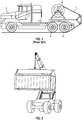
- For example, it is known, in many applications, to transport and deploy a temporary roadway system, wherein a road-covering track comprising interconnected profiled panels, is wound around a spool into a roll. In a known deployment method, the spool may be mounted, via a spool stand, on a flatbed body or trailer of a heavy goods vehicle, such that the winding axis of the spool is perpendicular to the longitudinal axis of the vehicle body. As illustrated in
Figure 1 of the drawings, the road-covering track 1 is drawn off thespool 2 and positioned under the vehicle's rear wheels 4. Thevehicle 3 then reverses, causing the road-coveringtrack 2 to be removed from therotating spool 2 and laid onto the ground under tension. - Other methods for deployment of this type of road-covering track are also known, that employ vehicles such as a tele-handler or wheeled loader, but they all operate in much the same manner as described above, whereby a constant tensioning device is used to automatically lay the roadway in tension and the laying process is determined by the speed of the moving vehicle. An alternative method of deployment may be performed by means of a remote control device that requires the operator and driver to synchronise the speed of vehicle travel with the speed of spool rotation. The operator depresses the spool rotation button on the pendant control to correspond with the travelling speed of the vehicle. If the electrical system fails, the operator can use hydraulic manual override levers to rotate the spool and, if complete hydraulic failure occurs, the operator can operate a manual handpump to release the spool rotation and the roadway can be manually pulled from the spool and placed under the vehicle's wheels.
- However, all of the above-mentioned deployment methods require the provision of a suitable vehicle to facilitate them, as well as to transport the rolled resource to the desired location, and, if such a vehicle is not normally used within the environment, the provision of such a vehicle specifically for this purpose significantly increases the cost of using the required resource and, therefore, the overall cost of an operation.
- It would therefore be desirable to provide a deployment/recovery system for coiled resources of the type described above, that does not require the provision and use of a specific type of vehicle.
- In accordance with a first aspect of the present invention, there is provided apparatus for deployment, recovery and/or storage of a resource comprising a flexible length of equipment capable of being wound on a spool, the apparatus comprising a rigid container shaped and configured to be handled by a specified vehicle type, the container having at least a base and a pair of opposing end walls, and an open side or an opening in a side wall thereof, wherein, on said base between said opposing end walls, there is provided a mounting member on which said spool is or can be mounted for rotation about its longitudinal axis.
- In an exemplary embodiment of the invention, at least one door may be hingedly mounted on one side across said opening. The apparatus may comprise a pair of door members hingedly mounted on opposing sides of said opening. Each of said door members may comprise a first panel hingedly connected to a second panel, said second panel being hingedly mounted on a respective side of said opening. In an alternative exemplary embodiment, one or more roller, or sliding, doors may be mounted across said opening. In yet another exemplary embodiment, the container comprises a flatrack device, comprising a base and two end walls and having open opposing sides.
- Apparatus according to an exemplary embodiment may comprise a container formed of corrugated weathering steel, and the external dimensions of said container may conform with the ISO 668 International Standard. The base of said container may be provided with a pair of fork pockets. Optionally, the corners of said container may each comprise a corner casting assembly.
- In an exemplary embodiment, a drive system may be provided within said container for rotating said spool. The drive system may comprise a hydraulic system. The apparatus may further comprise an integral compartment for storing hydraulic connectors for said hydraulic system.
- The apparatus may comprise a conduit within said housing, said conduit having an inlet adjacent a side edge of said container. In this case, the container may comprise a water hydrant connector member for enabling a water hydrant to be connected thereto, said connector member being communicably coupled to said conduit inlet. The conduit may comprise one or more apertures configured to create jets of water when a pressurised water supply is applied at said inlet of said conduit. A base of said container may be provided with one or more drainage apertures. Thus, the base of said container may comprise or include a sheet of mesh material.
- In an exemplary embodiment, the container may comprise one or more storage compartments; and/or a ladder may be mounted or otherwise provided on said container, said ladder extending substantially vertically along a side wall of said container.
- According to another aspect of the present invention, there is provided a method of manufacturing apparatus substantially as described above, comprising providing a rigid container externally shaped and configured to conform to the ISO 668 -
Series 1 freight containers International Standard, the container having at least a base and a pair of opposing end walls, and mounting on said base between said end walls, a spool on which is wound a flexible length of equipment such that said spool is rotatable about its longitudinal axis within said container. - The above-mentioned equipment may comprise a surface-covering track comprised of interconnected panels.
- These and other aspects of the present invention will be apparent from the following specific description, in which embodiments of the present invention are described, by way of examples only, and with reference to the accompanying drawings, in which:
-
Figure 1 is a schematic perspective view of a conventional heavy goods vehicle in a method of deployment of a surface-covering trackway according to an example of the prior art; -
Figure 2 is a perspective view of a typical rough terrain container handling vehicle, with which an exemplary embodiment of the present invention may be used; -
Figure 2A is a perspective view of a conventional flatrack device; -
Figure 3 is a schematic perspective front view of apparatus according to an exemplary embodiment of the present invention, with the doors thereof in a closed configuration; -
Figure 4 is a schematic perspective rear view of the apparatus ofFigure 3 ; -
Figure 5 is a schematic perspective front view of the apparatus ofFigure 3 , with the doors open, ready for deployment; -
Figure 5A is a schematic close-up view of the section marked A inFigure 5 ; -
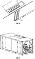
Figure 6 is a schematic close-up partial view of the top of the apparatus ofFigure 3 , illustrating the hydraulic connections of the apparatus stored in the roof of the container thereof; -
Figure 7 is a schematic perspective view of the apparatus ofFigure 3 , with the end wall removed to show the hydraulic system of the apparatus housed within the container thereof; -
Figure 8 is a schematic diagram illustrating the apparatus of an exemplary embodiment of the invention coupled to a rough terrain container handling vehicle; and -
Figure 9 is a schematic diagram illustrating apparatus according to an exemplary embodiment of the present invention, when in use to deploy a road-covering track using the rough terrain container handling vehicle ofFigure 8 . - Shipping containers have been used to transport goods, resources and equipment around the world for many years. The ISO International Standard, ISO 668 -
Series 1 Freight Containers, classifies intermodal shipping containers and standardises their size and weight specification, with the purpose of regulating, amongst other things, internal and external dimensions of containers, as well as minimum door opening size, where applicable. Lengths of containers vary greatly, but the most common containers in current use are the twenty and forty foot standard length boxes of the so-called dry freight design. These typical containers are rectangular, closed box models with doors fitted, either at one end or on one side, and made of corrugated weathering steel. Each of the eight corners has an essential corner casting which, together, form a standardised rotating connector for securing shipping containers, with the primary purpose of locking a container into place, and for lifting of the containers by a container handling vehicle. An alternative container, known as a flatrack, is illustrated inFigure 2A of the drawings. As shown, this type of container comprises a base and a pair of opposing end walls only, with an open top and side 'walls'. For the avoidance of doubt, it will be appreciated that the present invention is applicable to both closed and flatrack containers and is not necessarily intended to be limited in this regard. - Many different types of container handling vehicle are known and widely used in various respective environments. For example, a large proportion of ISO 20 foot containers have fork pockets built into the base of the container, which allow forklift tines to enter under the container, and enable a standard forklift to lift it (as long as the forklift is rated to lift the payload). However, for containers that do not have integral fork pockets, or for payloads greater than those for which a forklift would be suitable, other container handling vehicles are in widespread use. Specialised container handling vehicles are also known, designed for use in specific environments and/or specific tasks and operations. For example, rough terrain container handling (RTCH) vehicles, which are designed and used to lift and move ISO shipping containers on rough terrain, on and off beach landing craft and, as such, are particularly commonly provided in military environments, where having this capability permanently available on-site is critical to an operation. A typical RTCH vehicle is shown in
Figure 2 of the drawings, by way of example and for illustrative purposes only. - Thus aspects of the present invention are intended to provide a convenient deployment system for coiled resources of the type described above, for use in environments where a container handling vehicle is readily available and additional vehicular resource is, therefore, not required to be provided in order to enable deployment and recovery of the above-mentioned resources within those environments.
- Referring to
Figure 3 of the drawings, apparatus according to an exemplary embodiment of the present invention comprises acontainer 10 in a closed configuration. In this specific exemplary embodiment of the present invention, thecontainer 10 is constructed to comply with the size specification for the ISO 668 1C standard in respect of a twenty foot shipping container. Thus, the container in this case is a rectangular closed box with a pair ofdoors 12 fitted across a door opening across one side thereof, the container having a length of 6.048m and a width and height of 2.438m each. Eachdoor 12 hingedly mounted across the side of thecontainer 10 by means of a first vertical hinge member or set ofhinge members 12a, and the doors themselves are formed of two panels hingedly mounted together by means of a second vertical hinge member or set ofhinge members 12b. The container may be made of any suitable material, such as corrugated weathering steel, and each of the eight corners has acorner casting assembly 14, as described above. The base of the container is provided with a pair offork pockets 16, and the upper surface of the container is formed with a container section having aremovable cover 18. - Referring additionally to
Figure 4 of the drawings, a pair of storage compartments 20 is provided at the rear of thecontainer 10. As shown inFigure 6 of the drawings, the compartment provided in the roof of thecontainer 10 houses auxiliaryhydraulic connectors 21 when they are not required for use, and, at the rear of thecontainer 10, there is provided anaccess ladder 26 to enable an operative to climb to the roof of the container to access the compartment. Thecontainer 10 defines a hydraulic cabinet, denoted generally at 22, in which the hydraulic system for driving the deployment assembly is housed, and afurther access ladder 28 is provided at the rear of thecontainer 10 to enable an operative to access the hydraulic cabinet, as required, via a cover in the roof of thecontainer 10. Awater hydrant connection 24 is provided in an end wall of thecontainer 10 to enable water to be introduced into the container to clean the deployment assembly. - Referring now to
Figure 5 , within thecontainer 10, there is housed a deployment assembly denoted generally at 30. The deployment assembly comprises aspool 32 on which the resource, such as surface-covering track (not shown) is wound, when not in use. Thespool 32 comprises a pair of opposing, substantially circular end plates with a generally cylindrical support member extending therebetween, and is of substantially the same configuration as a conventional spool for this purpose. Thespool 30 is mounted within the container onframe 34 so as to be rotatable therein about an axis parallel to the longitudinal axis of thecontainer 10. A set of spaced apart guidemember 36 is provided along the lower side edge of the door opening, each guide roller comprising a set of rollers mounted in side-by-side relation and configured to rotate about an axis parallel to the longitudinal axis of thecontainer 10. Aconduit 38 runs along the rear lower side edge inside the container, the conduit being formed with a series ofapertures 40 arranged in spaced apart location along its length. When water is introduced into theconduit 38, under pressure, via thewater hydrant connection 24, jets of water are propelled from theapertures 40 to cleaning the spool and/or the resource wound thereon. The floor of the container comprises apertures, or may be formed of mesh, in order to allow the water to drain from the container. - Referring now to
Figures 8 and 9 of the drawings, in use, a rough terrain container handling (RTCH)vehicle 42 transports thecontainer 10, including the deployment assembly, to a desired location. During transportation, thecontainer 10 is oriented such that thedoors 12 of the container face thevehicle 42. At the desired location, thecontainer 10 is lowered to the ground and thedoors 12 are opening. The hydraulic power system is used to power thespool 30, causing it to rotate and feed the road-coveringtrack 44 from thespool 30. The end of the road-coveringtrack 44 is placed under thefront wheels 46 of the vehicle and the vehicle is then driven forward, over the road-coveringtrack 44 to pull the road-covering track from the spool and lay it, under tension, on the ground. It will be appreciated that other methods of deployment of the road-covering track (or other resource wound on the spool) can be used, as described above, and the present invention is not necessarily intended to be limited in this regard. - It will be appreciated by a person skilled in the art, from the foregoing description, that modifications and variations can be made to the described embodiments, without departing from the scope of the invention as defined by the appended claims. For example, it will be appreciated that the invention is not necessarily limited to the size of the container - the size of the container is limited only by the specification and capabilities of the vehicle required to transport and deploy the resource held therein. Furthermore, a preferred method of deployment is described above, but it will be appreciated that the method of operation of the apparatus of the present invention is not necessarily intended to be limited in this regard. Thus, in the above-described method, a constant tensioning device is used to automatically lay the roadway in tension and the laying process is determined by the speed of the moving vehicle. However, an alternative method of deployment may be performed by means of a remote control device that requires the operator and driver to synchronise the speed of vehicle travel with the speed of spool rotation. The operator depresses the spool rotation button on the pendant/joystick control to correspond with the travelling speed of the vehicle. If the electrical system fails, the operator can use hydraulic manual override levers to rotate the spool and, if complete hydraulic failure occurs, the operator can operate a manual handpump to release the spool rotation and the roadway can be manually pulled from the spool and placed under the vehicle's wheels.
Claims (15)
- Apparatus for deployment, recovery and/or storage of a resource comprising a flexible length of equipment capable of being wound on a spool, the apparatus comprising a rigid container shaped and configured to be handled by a specified vehicle type, the container having at least a base and a pair of opposing end walls, and an open side or an opening in a side wall thereof, wherein, on said base between said opposing end walls, there is provided a mounting member on which said spool is or can be mounted for rotation about its longitudinal axis.
- Apparatus according to claim 1, wherein said container comprises an opening in a side wall thereof and at least one door is hingedly mounted on one side across said opening.
- Apparatus according to claim 2, comprising a pair of door members hingedly mounted on opposing sides of said opening.
- Apparatus according to claim 3, wherein each of said door members comprises a first panel hingedly connected to a second panel, said second panel being hingedly mounted on a respective side of said opening.
- Apparatus according to claim 1, wherein said container comprises an opening in a side wall thereof and one or more roller, or sliding, doors is/are mounted across said opening; or wherein said container comprises a flatrack device, comprising a base and two end walls and having open opposing sides; and, optionally, wherein said container is formed of corrugated weathering steel.
- Apparatus according to any of the preceding claims, wherein the external dimensions of said container conform to the ISO 668 International Standard.
- Apparatus according to any of the preceding claims, wherein the base of said container is provided with a pair of fork pockets.
- Apparatus according to any of the preceding claims, wherein the corners of said container each comprise a corner casting assembly.
- Apparatus according to any of the preceding claims, comprising a drive system provided within said container for rotating said spool about its longitudinal axis.
- Apparatus according to claim 9, wherein the drive system comprises a hydraulic system and, optionally, wherein said container comprises an integral compartment for storing hydraulic connectors for said hydraulic system.
- Apparatus according to any of the preceding claims, comprising a conduit within said container, said conduit having an inlet adjacent a side edge of said container, and, optionally, wherein the container comprises a water hydrant connector member for enabling a water hydrant to be connected thereto, said connector member being communicably coupled to said conduit inlet.
- Apparatus according to claim 11, wherein said conduit comprises one or more apertures configured to create jets of water when a pressurised water supply is applied at said inlet of said conduit.
- Apparatus according to any of the preceding claims, wherein said base of said container is provided with one or more drainage apertures and, optionally, wherein said base of said container comprises or includes a sheet of mesh material; and/or wherein the container comprises one or more storage compartments; and/or wherein a ladder is mounted or otherwise provided on said container, said ladder extending substantially vertically along a side wall of said container.
- A method of manufacturing apparatus according to claim 1, comprising providing a rigid container externally shaped and configured to conform to the ISO 668 - Series 1 freight containers International Standard, the container having at least a base and a pair of opposing end walls, and mounting on said base between said end walls, a spool on which is wound a flexible length of equipment such that said spool is rotatable about its longitudinal axis within said container.
- A method according to claim 14, wherein said equipment comprises a surface-covering track comprised of interconnected panels.
Applications Claiming Priority (1)
| Application Number | Priority Date | Filing Date | Title |
|---|---|---|---|
| GB1521274.9A GB2546471A (en) | 2015-12-02 | 2015-12-02 | Deployment system |
Publications (2)
| Publication Number | Publication Date |
|---|---|
| EP3176116A1 true EP3176116A1 (en) | 2017-06-07 |
| EP3176116B1 EP3176116B1 (en) | 2020-04-22 |
Family
ID=55177592
Family Applications (1)
| Application Number | Title | Priority Date | Filing Date |
|---|---|---|---|
| EP16201007.8A Active EP3176116B1 (en) | 2015-12-02 | 2016-11-28 | Deployment system |
Country Status (3)
| Country | Link |
|---|---|
| US (1) | US10669119B2 (en) |
| EP (1) | EP3176116B1 (en) |
| GB (1) | GB2546471A (en) |
Cited By (1)
| Publication number | Priority date | Publication date | Assignee | Title |
|---|---|---|---|---|
| CN109082981A (en) * | 2018-08-07 | 2018-12-25 | 青岛开疆拓土农业装备科技有限公司 | A kind of solar pavement automatic paving equipment |
Families Citing this family (1)
| Publication number | Priority date | Publication date | Assignee | Title |
|---|---|---|---|---|
| US20170291788A1 (en) * | 2016-04-07 | 2017-10-12 | Rockland, Inc. | Carrier for positioning erosion control barrier segments |
Citations (6)
| Publication number | Priority date | Publication date | Assignee | Title |
|---|---|---|---|---|
| WO1999009255A1 (en) * | 1997-08-14 | 1999-02-25 | Faun Municipal Vehicles Limited | Device for the laying of a traversable temporary roadway system |
| WO2005014457A2 (en) * | 2003-07-11 | 2005-02-17 | Engineered Support Systems, Inc. | Systems and method for the rapid deployment of piping |
| CN201411622Y (en) * | 2008-07-31 | 2010-02-24 | 泰安航天特种车有限公司 | Road surface recovery cleaning device paved by soft-sand road surface emergent building car |
| CN203112258U (en) * | 2013-03-27 | 2013-08-07 | 天津市普盛科技发展有限公司 | Box type coil cable winch |
| GB2502661A (en) * | 2013-02-20 | 2013-12-04 | Renovagen Ltd | A mobile solar power plant |
| WO2014101952A1 (en) * | 2012-12-28 | 2014-07-03 | Prysmian S.P.A. | Container based by-pass module for electric power lines |
Family Cites Families (17)
| Publication number | Priority date | Publication date | Assignee | Title |
|---|---|---|---|---|
| US4103841A (en) * | 1977-08-26 | 1978-08-01 | Super Products Corporation | Hose reel apparatus |
| NL8402751A (en) | 1984-09-10 | 1986-04-01 | Philips Nv | APPARATUS FOR REPROCESSING STAINLESS AND ETCHING LIQUIDS. |
| DE3512589A1 (en) * | 1985-04-06 | 1986-10-16 | Fried. Krupp Gmbh, 4300 Essen | ROLLABLE FLOORING AND DEVICE FOR WINDING UP AN INSTALLED FLOORING |
| US4669145A (en) * | 1985-09-25 | 1987-06-02 | Kehr Edwin A | Hose reel system |
| US6299008B1 (en) * | 1999-09-28 | 2001-10-09 | Boh Environmental, Llc | Transport and storage system |
| US7496983B2 (en) * | 2004-11-08 | 2009-03-03 | Kostigian John V | Gymnasium floor covering storage and cleaning roller |
| GB0601375D0 (en) * | 2006-01-24 | 2006-03-01 | Reynard Kenneth | Transportable load carrying platform |
| US8079778B2 (en) * | 2008-05-02 | 2011-12-20 | Byron Kelly Colkitt | Geotextile applicator device and method |
| US20100025407A1 (en) * | 2008-08-04 | 2010-02-04 | Lynn Benson | Method Of Converting Shipping Containers To Fluid Tanks |
| US8974311B2 (en) * | 2010-08-10 | 2015-03-10 | Technology Licensing Corp. | Method and device for installing synthetic turf |
| US8820559B2 (en) * | 2010-08-10 | 2014-09-02 | Lake Effect Advisors, Inc. | Shipping containers for flowable materials |
| US8784002B2 (en) * | 2011-07-20 | 2014-07-22 | Property Props, Inc. | Track system for use with vehicles and methods regarding same |
| MX2014011427A (en) * | 2012-03-29 | 2017-06-16 | Valspar Sourcing Inc | Waterborne underbody coating system. |
| DE202012006322U1 (en) * | 2012-07-02 | 2012-09-11 | Rewald Gmbh | Vertical ladder for roll-off containers |
| US8784007B2 (en) * | 2012-11-09 | 2014-07-22 | Walter N. Wilson | Apparatus for covering a land area with a heavy wide width flexible sheeting |
| US20140299706A1 (en) * | 2013-04-03 | 2014-10-09 | Joseph J. DiSabantonio, III | Stackable pallet system having foldable end boards |
| CN105064185A (en) * | 2015-08-06 | 2015-11-18 | 中国石油天然气集团公司 | Wetland paving method and recycling method |
-
2015
- 2015-12-02 GB GB1521274.9A patent/GB2546471A/en not_active Withdrawn
-
2016
- 2016-09-27 US US15/277,552 patent/US10669119B2/en active Active
- 2016-11-28 EP EP16201007.8A patent/EP3176116B1/en active Active
Patent Citations (6)
| Publication number | Priority date | Publication date | Assignee | Title |
|---|---|---|---|---|
| WO1999009255A1 (en) * | 1997-08-14 | 1999-02-25 | Faun Municipal Vehicles Limited | Device for the laying of a traversable temporary roadway system |
| WO2005014457A2 (en) * | 2003-07-11 | 2005-02-17 | Engineered Support Systems, Inc. | Systems and method for the rapid deployment of piping |
| CN201411622Y (en) * | 2008-07-31 | 2010-02-24 | 泰安航天特种车有限公司 | Road surface recovery cleaning device paved by soft-sand road surface emergent building car |
| WO2014101952A1 (en) * | 2012-12-28 | 2014-07-03 | Prysmian S.P.A. | Container based by-pass module for electric power lines |
| GB2502661A (en) * | 2013-02-20 | 2013-12-04 | Renovagen Ltd | A mobile solar power plant |
| CN203112258U (en) * | 2013-03-27 | 2013-08-07 | 天津市普盛科技发展有限公司 | Box type coil cable winch |
Cited By (2)
| Publication number | Priority date | Publication date | Assignee | Title |
|---|---|---|---|---|
| CN109082981A (en) * | 2018-08-07 | 2018-12-25 | 青岛开疆拓土农业装备科技有限公司 | A kind of solar pavement automatic paving equipment |
| CN109082981B (en) * | 2018-08-07 | 2020-09-25 | 广东恒大路桥建设有限公司 | Automatic paving equipment of solar energy road surface |
Also Published As
| Publication number | Publication date |
|---|---|
| US10669119B2 (en) | 2020-06-02 |
| US20170158456A1 (en) | 2017-06-08 |
| GB2546471A (en) | 2017-07-26 |
| EP3176116B1 (en) | 2020-04-22 |
| GB201521274D0 (en) | 2016-01-13 |
Similar Documents
| Publication | Publication Date | Title |
|---|---|---|
| EP3263402B1 (en) | Container for salvaging damaged vehicles and method for salvaging a damaged vehicle | |
| CN104837761A (en) | System and method for placing tarpaulin over load | |
| US7874107B1 (en) | Convertible hard side shelter | |
| US9567168B1 (en) | Mobile crossdock | |
| EP3176116B1 (en) | Deployment system | |
| CA2743810A1 (en) | Apparatus and method for applying a tarp to trucking cargo | |
| EP2678252A1 (en) | Sea container that can be closed on all sides | |
| US11724627B2 (en) | Flexible tank with cape, discharge apparatus and method | |
| US7621410B1 (en) | Removable externally mounted bridge crane for shipping containers | |
| US9968811B2 (en) | Firefighting or rescue apparatus including an extendable crosslay hose bed | |
| US10662042B2 (en) | Portable rumble strip retrieval system | |
| US4130125A (en) | Light-weight, easy-erecting barge hatch cover | |
| US4393888A (en) | Method of protecting contents of a barge while in transit | |
| US3187830A (en) | Motorized dolly | |
| KR20210026968A (en) | Automatic cover for loading box of freight car | |
| JP2009052282A (en) | Re-roofing unit and re-roofing method for existing building | |
| EP1872991A1 (en) | Covering system for transportable containers | |
| EP4039634B1 (en) | Cover support unit for supporting objects on/beneath a ceiling | |
| KR20170047188A (en) | stacker cover device of Truck | |
| WO2016083723A1 (en) | Automated device for handling and transporting metal sheets between the inside and the outside of a reservoir | |
| JP3711280B2 (en) | Mobile all-weather work building | |
| DE202023101886U1 (en) | Mobile extinguishing container | |
| WO2016187653A1 (en) | Fluid storage apparatus | |
| AU2015271969B2 (en) | Safety guard apparatus | |
| DE102021117044A1 (en) | Ceiling storage unit for storing items on/under a ceiling |
Legal Events
| Date | Code | Title | Description |
|---|---|---|---|
| AK | Designated contracting states |
Kind code of ref document: A1 Designated state(s): AL AT BE BG CH CY CZ DE DK EE ES FI FR GB GR HR HU IE IS IT LI LT LU LV MC MK MT NL NO PL PT RO RS SE SI SK SM TR |
|
| AX | Request for extension of the european patent |
Extension state: BA ME |
|
| PUAI | Public reference made under article 153(3) epc to a published international application that has entered the european phase |
Free format text: ORIGINAL CODE: 0009012 |
|
| STAA | Information on the status of an ep patent application or granted ep patent |
Free format text: STATUS: THE APPLICATION HAS BEEN PUBLISHED |
|
| STAA | Information on the status of an ep patent application or granted ep patent |
Free format text: STATUS: REQUEST FOR EXAMINATION WAS MADE |
|
| 17P | Request for examination filed |
Effective date: 20171114 |
|
| RBV | Designated contracting states (corrected) |
Designated state(s): AL AT BE BG CH CY CZ DE DK EE ES FI FR GB GR HR HU IE IS IT LI LT LU LV MC MK MT NL NO PL PT RO RS SE SI SK SM TR |
|
| STAA | Information on the status of an ep patent application or granted ep patent |
Free format text: STATUS: EXAMINATION IS IN PROGRESS |
|
| 17Q | First examination report despatched |
Effective date: 20180328 |
|
| GRAP | Despatch of communication of intention to grant a patent |
Free format text: ORIGINAL CODE: EPIDOSNIGR1 |
|
| STAA | Information on the status of an ep patent application or granted ep patent |
Free format text: STATUS: GRANT OF PATENT IS INTENDED |
|
| INTG | Intention to grant announced |
Effective date: 20191119 |
|
| GRAS | Grant fee paid |
Free format text: ORIGINAL CODE: EPIDOSNIGR3 |
|
| GRAA | (expected) grant |
Free format text: ORIGINAL CODE: 0009210 |
|
| STAA | Information on the status of an ep patent application or granted ep patent |
Free format text: STATUS: THE PATENT HAS BEEN GRANTED |
|
| AK | Designated contracting states |
Kind code of ref document: B1 Designated state(s): AL AT BE BG CH CY CZ DE DK EE ES FI FR GB GR HR HU IE IS IT LI LT LU LV MC MK MT NL NO PL PT RO RS SE SI SK SM TR |
|
| REG | Reference to a national code |
Ref country code: CH Ref legal event code: EP |
|
| REG | Reference to a national code |
Ref country code: IE Ref legal event code: FG4D |
|
| REG | Reference to a national code |
Ref country code: DE Ref legal event code: R096 Ref document number: 602016034420 Country of ref document: DE |
|
| REG | Reference to a national code |
Ref country code: AT Ref legal event code: REF Ref document number: 1259825 Country of ref document: AT Kind code of ref document: T Effective date: 20200515 |
|
| REG | Reference to a national code |
Ref country code: NL Ref legal event code: FP |
|
| REG | Reference to a national code |
Ref country code: LT Ref legal event code: MG4D |
|
| PG25 | Lapsed in a contracting state [announced via postgrant information from national office to epo] |
Ref country code: IS Free format text: LAPSE BECAUSE OF FAILURE TO SUBMIT A TRANSLATION OF THE DESCRIPTION OR TO PAY THE FEE WITHIN THE PRESCRIBED TIME-LIMIT Effective date: 20200822 Ref country code: NO Free format text: LAPSE BECAUSE OF FAILURE TO SUBMIT A TRANSLATION OF THE DESCRIPTION OR TO PAY THE FEE WITHIN THE PRESCRIBED TIME-LIMIT Effective date: 20200722 Ref country code: GR Free format text: LAPSE BECAUSE OF FAILURE TO SUBMIT A TRANSLATION OF THE DESCRIPTION OR TO PAY THE FEE WITHIN THE PRESCRIBED TIME-LIMIT Effective date: 20200723 Ref country code: FI Free format text: LAPSE BECAUSE OF FAILURE TO SUBMIT A TRANSLATION OF THE DESCRIPTION OR TO PAY THE FEE WITHIN THE PRESCRIBED TIME-LIMIT Effective date: 20200422 Ref country code: SE Free format text: LAPSE BECAUSE OF FAILURE TO SUBMIT A TRANSLATION OF THE DESCRIPTION OR TO PAY THE FEE WITHIN THE PRESCRIBED TIME-LIMIT Effective date: 20200422 Ref country code: PT Free format text: LAPSE BECAUSE OF FAILURE TO SUBMIT A TRANSLATION OF THE DESCRIPTION OR TO PAY THE FEE WITHIN THE PRESCRIBED TIME-LIMIT Effective date: 20200824 Ref country code: LT Free format text: LAPSE BECAUSE OF FAILURE TO SUBMIT A TRANSLATION OF THE DESCRIPTION OR TO PAY THE FEE WITHIN THE PRESCRIBED TIME-LIMIT Effective date: 20200422 |
|
| REG | Reference to a national code |
Ref country code: AT Ref legal event code: MK05 Ref document number: 1259825 Country of ref document: AT Kind code of ref document: T Effective date: 20200422 |
|
| PG25 | Lapsed in a contracting state [announced via postgrant information from national office to epo] |
Ref country code: BG Free format text: LAPSE BECAUSE OF FAILURE TO SUBMIT A TRANSLATION OF THE DESCRIPTION OR TO PAY THE FEE WITHIN THE PRESCRIBED TIME-LIMIT Effective date: 20200722 Ref country code: RS Free format text: LAPSE BECAUSE OF FAILURE TO SUBMIT A TRANSLATION OF THE DESCRIPTION OR TO PAY THE FEE WITHIN THE PRESCRIBED TIME-LIMIT Effective date: 20200422 Ref country code: LV Free format text: LAPSE BECAUSE OF FAILURE TO SUBMIT A TRANSLATION OF THE DESCRIPTION OR TO PAY THE FEE WITHIN THE PRESCRIBED TIME-LIMIT Effective date: 20200422 Ref country code: HR Free format text: LAPSE BECAUSE OF FAILURE TO SUBMIT A TRANSLATION OF THE DESCRIPTION OR TO PAY THE FEE WITHIN THE PRESCRIBED TIME-LIMIT Effective date: 20200422 |
|
| PG25 | Lapsed in a contracting state [announced via postgrant information from national office to epo] |
Ref country code: AL Free format text: LAPSE BECAUSE OF FAILURE TO SUBMIT A TRANSLATION OF THE DESCRIPTION OR TO PAY THE FEE WITHIN THE PRESCRIBED TIME-LIMIT Effective date: 20200422 |
|
| REG | Reference to a national code |
Ref country code: DE Ref legal event code: R097 Ref document number: 602016034420 Country of ref document: DE |
|
| PG25 | Lapsed in a contracting state [announced via postgrant information from national office to epo] |
Ref country code: AT Free format text: LAPSE BECAUSE OF FAILURE TO SUBMIT A TRANSLATION OF THE DESCRIPTION OR TO PAY THE FEE WITHIN THE PRESCRIBED TIME-LIMIT Effective date: 20200422 Ref country code: EE Free format text: LAPSE BECAUSE OF FAILURE TO SUBMIT A TRANSLATION OF THE DESCRIPTION OR TO PAY THE FEE WITHIN THE PRESCRIBED TIME-LIMIT Effective date: 20200422 Ref country code: SM Free format text: LAPSE BECAUSE OF FAILURE TO SUBMIT A TRANSLATION OF THE DESCRIPTION OR TO PAY THE FEE WITHIN THE PRESCRIBED TIME-LIMIT Effective date: 20200422 Ref country code: DK Free format text: LAPSE BECAUSE OF FAILURE TO SUBMIT A TRANSLATION OF THE DESCRIPTION OR TO PAY THE FEE WITHIN THE PRESCRIBED TIME-LIMIT Effective date: 20200422 Ref country code: RO Free format text: LAPSE BECAUSE OF FAILURE TO SUBMIT A TRANSLATION OF THE DESCRIPTION OR TO PAY THE FEE WITHIN THE PRESCRIBED TIME-LIMIT Effective date: 20200422 Ref country code: IT Free format text: LAPSE BECAUSE OF FAILURE TO SUBMIT A TRANSLATION OF THE DESCRIPTION OR TO PAY THE FEE WITHIN THE PRESCRIBED TIME-LIMIT Effective date: 20200422 Ref country code: CZ Free format text: LAPSE BECAUSE OF FAILURE TO SUBMIT A TRANSLATION OF THE DESCRIPTION OR TO PAY THE FEE WITHIN THE PRESCRIBED TIME-LIMIT Effective date: 20200422 Ref country code: ES Free format text: LAPSE BECAUSE OF FAILURE TO SUBMIT A TRANSLATION OF THE DESCRIPTION OR TO PAY THE FEE WITHIN THE PRESCRIBED TIME-LIMIT Effective date: 20200422 |
|
| PG25 | Lapsed in a contracting state [announced via postgrant information from national office to epo] |
Ref country code: PL Free format text: LAPSE BECAUSE OF FAILURE TO SUBMIT A TRANSLATION OF THE DESCRIPTION OR TO PAY THE FEE WITHIN THE PRESCRIBED TIME-LIMIT Effective date: 20200422 Ref country code: SK Free format text: LAPSE BECAUSE OF FAILURE TO SUBMIT A TRANSLATION OF THE DESCRIPTION OR TO PAY THE FEE WITHIN THE PRESCRIBED TIME-LIMIT Effective date: 20200422 |
|
| PLBE | No opposition filed within time limit |
Free format text: ORIGINAL CODE: 0009261 |
|
| STAA | Information on the status of an ep patent application or granted ep patent |
Free format text: STATUS: NO OPPOSITION FILED WITHIN TIME LIMIT |
|
| 26N | No opposition filed |
Effective date: 20210125 |
|
| PG25 | Lapsed in a contracting state [announced via postgrant information from national office to epo] |
Ref country code: SI Free format text: LAPSE BECAUSE OF FAILURE TO SUBMIT A TRANSLATION OF THE DESCRIPTION OR TO PAY THE FEE WITHIN THE PRESCRIBED TIME-LIMIT Effective date: 20200422 |
|
| PG25 | Lapsed in a contracting state [announced via postgrant information from national office to epo] |
Ref country code: MC Free format text: LAPSE BECAUSE OF FAILURE TO SUBMIT A TRANSLATION OF THE DESCRIPTION OR TO PAY THE FEE WITHIN THE PRESCRIBED TIME-LIMIT Effective date: 20200422 |
|
| REG | Reference to a national code |
Ref country code: CH Ref legal event code: PL |
|
| PG25 | Lapsed in a contracting state [announced via postgrant information from national office to epo] |
Ref country code: LU Free format text: LAPSE BECAUSE OF NON-PAYMENT OF DUE FEES Effective date: 20201128 |
|
| REG | Reference to a national code |
Ref country code: BE Ref legal event code: MM Effective date: 20201130 |
|
| PG25 | Lapsed in a contracting state [announced via postgrant information from national office to epo] |
Ref country code: CH Free format text: LAPSE BECAUSE OF NON-PAYMENT OF DUE FEES Effective date: 20201130 Ref country code: LI Free format text: LAPSE BECAUSE OF NON-PAYMENT OF DUE FEES Effective date: 20201130 |
|
| PG25 | Lapsed in a contracting state [announced via postgrant information from national office to epo] |
Ref country code: IE Free format text: LAPSE BECAUSE OF NON-PAYMENT OF DUE FEES Effective date: 20201128 |
|
| PG25 | Lapsed in a contracting state [announced via postgrant information from national office to epo] |
Ref country code: TR Free format text: LAPSE BECAUSE OF FAILURE TO SUBMIT A TRANSLATION OF THE DESCRIPTION OR TO PAY THE FEE WITHIN THE PRESCRIBED TIME-LIMIT Effective date: 20200422 Ref country code: MT Free format text: LAPSE BECAUSE OF FAILURE TO SUBMIT A TRANSLATION OF THE DESCRIPTION OR TO PAY THE FEE WITHIN THE PRESCRIBED TIME-LIMIT Effective date: 20200422 Ref country code: CY Free format text: LAPSE BECAUSE OF FAILURE TO SUBMIT A TRANSLATION OF THE DESCRIPTION OR TO PAY THE FEE WITHIN THE PRESCRIBED TIME-LIMIT Effective date: 20200422 |
|
| PG25 | Lapsed in a contracting state [announced via postgrant information from national office to epo] |
Ref country code: MK Free format text: LAPSE BECAUSE OF FAILURE TO SUBMIT A TRANSLATION OF THE DESCRIPTION OR TO PAY THE FEE WITHIN THE PRESCRIBED TIME-LIMIT Effective date: 20200422 |
|
| PG25 | Lapsed in a contracting state [announced via postgrant information from national office to epo] |
Ref country code: BE Free format text: LAPSE BECAUSE OF NON-PAYMENT OF DUE FEES Effective date: 20201130 |
|
| PGFP | Annual fee paid to national office [announced via postgrant information from national office to epo] |
Ref country code: NL Payment date: 20231122 Year of fee payment: 8 |
|
| PGFP | Annual fee paid to national office [announced via postgrant information from national office to epo] |
Ref country code: GB Payment date: 20231009 Year of fee payment: 8 |
|
| PGFP | Annual fee paid to national office [announced via postgrant information from national office to epo] |
Ref country code: FR Payment date: 20231124 Year of fee payment: 8 Ref country code: DE Payment date: 20231120 Year of fee payment: 8 |