EP3175963A1 - Method of coating an intramedullary nail with flowable material - Google Patents
Method of coating an intramedullary nail with flowable material Download PDFInfo
- Publication number
- EP3175963A1 EP3175963A1 EP17150540.7A EP17150540A EP3175963A1 EP 3175963 A1 EP3175963 A1 EP 3175963A1 EP 17150540 A EP17150540 A EP 17150540A EP 3175963 A1 EP3175963 A1 EP 3175963A1
- Authority
- EP
- European Patent Office
- Prior art keywords
- tubular member
- nail
- flowable material
- advancing
- sidewall
- Prior art date
- Legal status (The legal status is an assumption and is not a legal conclusion. Google has not performed a legal analysis and makes no representation as to the accuracy of the status listed.)
- Granted
Links
- 239000000463 material Substances 0.000 title claims abstract description 83
- 230000009969 flowable effect Effects 0.000 title claims abstract description 68
- 238000000034 method Methods 0.000 title claims abstract description 36
- 239000011248 coating agent Substances 0.000 title claims abstract description 9
- 238000000576 coating method Methods 0.000 title claims abstract description 9
- 238000003780 insertion Methods 0.000 claims abstract description 12
- 230000037431 insertion Effects 0.000 claims abstract description 12
- 230000008878 coupling Effects 0.000 claims description 14
- 238000010168 coupling process Methods 0.000 claims description 14
- 238000005859 coupling reaction Methods 0.000 claims description 14
- 239000004568 cement Substances 0.000 description 17
- 238000005516 engineering process Methods 0.000 description 16
- 229920001296 polysiloxane Polymers 0.000 description 9
- 230000003115 biocidal effect Effects 0.000 description 7
- 210000000988 bone and bone Anatomy 0.000 description 7
- 230000008569 process Effects 0.000 description 6
- 239000007943 implant Substances 0.000 description 4
- 239000000203 mixture Substances 0.000 description 4
- 206010017076 Fracture Diseases 0.000 description 3
- 239000003242 anti bacterial agent Substances 0.000 description 2
- 230000015572 biosynthetic process Effects 0.000 description 2
- 238000002513 implantation Methods 0.000 description 2
- 238000004519 manufacturing process Methods 0.000 description 2
- 239000012528 membrane Substances 0.000 description 2
- 230000003014 reinforcing effect Effects 0.000 description 2
- 208000036829 Device dislocation Diseases 0.000 description 1
- 230000001419 dependent effect Effects 0.000 description 1
- 239000013536 elastomeric material Substances 0.000 description 1
- 230000007717 exclusion Effects 0.000 description 1
- 230000035876 healing Effects 0.000 description 1
- 210000002758 humerus Anatomy 0.000 description 1
- 208000015181 infectious disease Diseases 0.000 description 1
- 238000012986 modification Methods 0.000 description 1
- 230000004048 modification Effects 0.000 description 1
- 230000008520 organization Effects 0.000 description 1
- 230000002265 prevention Effects 0.000 description 1
- 230000001681 protective effect Effects 0.000 description 1
- 230000000087 stabilizing effect Effects 0.000 description 1
- 210000002303 tibia Anatomy 0.000 description 1
- 239000012780 transparent material Substances 0.000 description 1
- 210000000689 upper leg Anatomy 0.000 description 1
Images




Classifications
-
- B—PERFORMING OPERATIONS; TRANSPORTING
- B29—WORKING OF PLASTICS; WORKING OF SUBSTANCES IN A PLASTIC STATE IN GENERAL
- B29C—SHAPING OR JOINING OF PLASTICS; SHAPING OF MATERIAL IN A PLASTIC STATE, NOT OTHERWISE PROVIDED FOR; AFTER-TREATMENT OF THE SHAPED PRODUCTS, e.g. REPAIRING
- B29C39/00—Shaping by casting, i.e. introducing the moulding material into a mould or between confining surfaces without significant moulding pressure; Apparatus therefor
- B29C39/02—Shaping by casting, i.e. introducing the moulding material into a mould or between confining surfaces without significant moulding pressure; Apparatus therefor for making articles of definite length, i.e. discrete articles
- B29C39/10—Shaping by casting, i.e. introducing the moulding material into a mould or between confining surfaces without significant moulding pressure; Apparatus therefor for making articles of definite length, i.e. discrete articles incorporating preformed parts or layers, e.g. casting around inserts or for coating articles
-
- A—HUMAN NECESSITIES
- A61—MEDICAL OR VETERINARY SCIENCE; HYGIENE
- A61B—DIAGNOSIS; SURGERY; IDENTIFICATION
- A61B17/00—Surgical instruments, devices or methods
- A61B17/56—Surgical instruments or methods for treatment of bones or joints; Devices specially adapted therefor
- A61B17/58—Surgical instruments or methods for treatment of bones or joints; Devices specially adapted therefor for osteosynthesis, e.g. bone plates, screws or setting implements
- A61B17/68—Internal fixation devices, including fasteners and spinal fixators, even if a part thereof projects from the skin
- A61B17/72—Intramedullary devices, e.g. pins or nails
-
- B—PERFORMING OPERATIONS; TRANSPORTING
- B29—WORKING OF PLASTICS; WORKING OF SUBSTANCES IN A PLASTIC STATE IN GENERAL
- B29C—SHAPING OR JOINING OF PLASTICS; SHAPING OF MATERIAL IN A PLASTIC STATE, NOT OTHERWISE PROVIDED FOR; AFTER-TREATMENT OF THE SHAPED PRODUCTS, e.g. REPAIRING
- B29C33/00—Moulds or cores; Details thereof or accessories therefor
-
- B—PERFORMING OPERATIONS; TRANSPORTING
- B29—WORKING OF PLASTICS; WORKING OF SUBSTANCES IN A PLASTIC STATE IN GENERAL
- B29C—SHAPING OR JOINING OF PLASTICS; SHAPING OF MATERIAL IN A PLASTIC STATE, NOT OTHERWISE PROVIDED FOR; AFTER-TREATMENT OF THE SHAPED PRODUCTS, e.g. REPAIRING
- B29C39/00—Shaping by casting, i.e. introducing the moulding material into a mould or between confining surfaces without significant moulding pressure; Apparatus therefor
- B29C39/22—Component parts, details or accessories; Auxiliary operations
- B29C39/24—Feeding the material into the mould
-
- B—PERFORMING OPERATIONS; TRANSPORTING
- B29—WORKING OF PLASTICS; WORKING OF SUBSTANCES IN A PLASTIC STATE IN GENERAL
- B29C—SHAPING OR JOINING OF PLASTICS; SHAPING OF MATERIAL IN A PLASTIC STATE, NOT OTHERWISE PROVIDED FOR; AFTER-TREATMENT OF THE SHAPED PRODUCTS, e.g. REPAIRING
- B29C39/00—Shaping by casting, i.e. introducing the moulding material into a mould or between confining surfaces without significant moulding pressure; Apparatus therefor
- B29C39/22—Component parts, details or accessories; Auxiliary operations
- B29C39/26—Moulds or cores
-
- A—HUMAN NECESSITIES
- A61—MEDICAL OR VETERINARY SCIENCE; HYGIENE
- A61B—DIAGNOSIS; SURGERY; IDENTIFICATION
- A61B17/00—Surgical instruments, devices or methods
- A61B2017/00526—Methods of manufacturing
-
- A—HUMAN NECESSITIES
- A61—MEDICAL OR VETERINARY SCIENCE; HYGIENE
- A61B—DIAGNOSIS; SURGERY; IDENTIFICATION
- A61B17/00—Surgical instruments, devices or methods
- A61B2017/00831—Material properties
- A61B2017/00889—Material properties antimicrobial, disinfectant
-
- B—PERFORMING OPERATIONS; TRANSPORTING
- B29—WORKING OF PLASTICS; WORKING OF SUBSTANCES IN A PLASTIC STATE IN GENERAL
- B29C—SHAPING OR JOINING OF PLASTICS; SHAPING OF MATERIAL IN A PLASTIC STATE, NOT OTHERWISE PROVIDED FOR; AFTER-TREATMENT OF THE SHAPED PRODUCTS, e.g. REPAIRING
- B29C33/00—Moulds or cores; Details thereof or accessories therefor
- B29C2033/0005—Moulds or cores; Details thereof or accessories therefor with transparent parts, e.g. permitting visual inspection of the interior of the cavity
-
- B—PERFORMING OPERATIONS; TRANSPORTING
- B29—WORKING OF PLASTICS; WORKING OF SUBSTANCES IN A PLASTIC STATE IN GENERAL
- B29K—INDEXING SCHEME ASSOCIATED WITH SUBCLASSES B29B, B29C OR B29D, RELATING TO MOULDING MATERIALS OR TO MATERIALS FOR MOULDS, REINFORCEMENTS, FILLERS OR PREFORMED PARTS, e.g. INSERTS
- B29K2705/00—Use of metals, their alloys or their compounds, for preformed parts, e.g. for inserts
-
- B—PERFORMING OPERATIONS; TRANSPORTING
- B29—WORKING OF PLASTICS; WORKING OF SUBSTANCES IN A PLASTIC STATE IN GENERAL
- B29L—INDEXING SCHEME ASSOCIATED WITH SUBCLASS B29C, RELATING TO PARTICULAR ARTICLES
- B29L2031/00—Other particular articles
- B29L2031/753—Medical equipment; Accessories therefor
- B29L2031/7546—Surgical equipment
Definitions
- the disclosure relates to a method of coating an intramedullary nail with flowable material.
- the present technology relates generally to cement coated rods and more specifically to a mold and related method for coating intramedullary (IM) rods with an antibiotic-loaded hardenable material.
- IM intramedullary
- a longitudinal rod or nail through the IM canal of the bone to assist in stabilizing long bones during bone healing.
- an IM nail that is coated with antibiotic-loaded cement to assist in treatment or prevention of infection.
- the IM nail can have an elongated metallic member that includes one or more cylindrical cavities that can be perpendicular to the long axis of the IM nail for receiving a fastener element, such as a transcortical screw.
- the IM nail can be positioned within the medullary cavity and can be secured to the proximal and distal fracture segments using transcortical screws, which penetrate both cortices of the bone, as well as pass through the cylindrical cavities formed in the IM nail.
- antibiotic-loaded cement can be introduced into an open end of a tube and an IM nail can be subsequently introduced into the tube. Once the antibiotic-loaded cement cures, the tube can be removed.
- This configuration and method can be unfavorable to a user as the flowable cement can be quite viscous. In this regard, filling a relatively long tube with such material can be difficult. In examples where the tube is formed of a relatively thin-walled elastomeric material, filling the tube can become more difficult as the tubing may expand during the introduction of the cement. In this regard, cement may be inhibited from flowing down the length of the tube.
- the tubing may expand during the delivery stroke, and then contract, allowing cement to flow back into the cement delivery device between delivery strokes.
- the insertion of the IM rod can be uncontrolled and generally messy as the cement out of the tube and/or can easily flow onto parts of the IM rod where it is undesired.
- a method of coating an intramedullary (IM) nail with flowable material can include, advancing the IM nail into a tubular member from an insertion end of the tubular member toward an opposite end of the tubular member.
- the flowable material can be advanced through a first port defined through a sidewall at a first location on the tubular member.
- the tubular member can be removed from the IM nail having the cured flowable material thereon.
- the method can further comprise advancing the flowable material through a second port through the sidewall at a second location, distinct from the first location, on the tubular member.
- the method can further comprise observing the flowable material advancing within the tubular member. The advancing of the flowable material can be stopped through the first port based on the flowable material advancing substantially toward the second port.
- the method can further comprise slidably translating the IM nail along at least two longitudinally extending protrusions formed on the inner cylindrical surface of the sidewall.
- the method can further comprise coupling a flowable material delivery device to a boss formed on the tubular member proximate to the first port.
- coupling can include one of threadably coupling, luer lock coupling, and nozzle coupling the flowable material delivery device to the tubular member.
- advancing the IM nail can comprise advancing the IM nail into the tubular member until a distal end of the IM nail engages a concave surface at the opposite end of the tubular member.
- Removing the tubular member can comprise cutting the tubular member away from the coated IM nail.
- Removing the tubular member can comprise pulling a pull member disposed on the tubular member causing a slit to the formed along the tubular member.
- a mold for forming a coated intramedullary (IM) nail can include a tubular member having an insertion end and an opposite end.
- the tubular member can comprise a sidewall extending along a longitudinal axis between an outer surface and an inner surface.
- the sidewall can define at least one threaded inlet port therealong.
- the tubular member can be configured to receive the IM nail therein.
- the tubular member can be further configured to locate a flowable material against the IM nail and the inner surface of the tubular member.
- the inner surface of the tubular member can comprise at least one inwardly and radially extending protrusion.
- the inner surface can comprise three inwardly extending protrusions radially spaced substantially equally to each other on the inner surface.
- the protrusions can extend substantially along the length of the tubular member between the insertion end and an opposite end.
- the protrusions can each include longitudinally spaced nibs extending inwardly toward the longitudinal axis.
- Each nib can have a nail engaging surface configured to engage the nail and offset the nail inwardly along the longitudinal axis and spaced from a remainder of the protrusion.
- the opposite end of the tubular member can be closed and define a concave surface.
- the tubular member can further comprise a first inlet port formed through the sidewall and configured to accept the flowable material therethrough.
- the first inlet port can comprise a threaded port extending outwardly from the outer surface.
- the tubular member can further comprise a plurality of threaded inlet ports spaced from each other and formed through the sidewall configured to accept flowable material therethrough.
- the sidewall can comprise a plurality of vent holes therealong.
- the plurality of vent holes can comprise at least one distinct row of vent holes formed longitudinally along the sidewall.
- the plurality of vent holes can comprise at least two distinct rows of vent holes, each row radially spaced between two adjacent protrusions.
- the mold can be transparent.
- the mold can be flexible.
- the mold can be cuttable.
- the mold can be formed of a material that releases from cured flowable material.
- the material can comprise silicone.
- the silicone can be reinforced silicone.
- the mold can further comprise a pull member disposed on the tubular member.
- the pull member can be configured to influence formation of a slit or cut on the tubular member upon pulling for removing the tubular member subsequent to curing of the flowable material.
- a sheath can be configured to be disposed onto the IM nail and inhibit introduction of the flowable material into the IM nail.
- the molds and related methods disclosed herein are specifically directed toward fabrication of antibiotic-loaded, cement-coated rods, the molds and methods disclosed herein may also be adapted to introduce other flowable material onto a surface of a prosthetic implant. Moreover, the molds and related methods disclosed herein may be used to create antibiotic-loaded, cement-coated implants applicable for use with other bones in the body. Therefore, it will be understood that the present description and the claims are applicable to any appropriate bone in the body. A non-limiting discussion of terms and phrases intended to aid understanding of the present technology is provided at the end of the specification.
- a mold that may be used to form a coated intramedullary (IM) nail according to one example of the present disclosure is shown and generally identified at reference numeral 10.
- the mold 10 can include a tubular member 12 having an insertion end 14 and an opposite end 16.
- the insertion end 14 defines an opening whereas the opposite end 16 provides a closed end 22.
- the closed end 22 can have a generally convex outer surface 24.
- the tubular member 12 can extend generally along a longitudinal axis 30.
- the tubular member 12 can have a sidewall 34 that has an outer surface 36 and an inner surface 38.
- the sidewall 34 is cylindrical however other cross-sections are contemplated.
- the sidewall 34 can generally extend along the longitudinal axis 30.
- the sidewall 34 defines a plurality of inlet ports 40a, 40b, 40c, and 40d.
- a corresponding plurality of boss structures 42a, 42b, 42c, and 42d can extend from the outer surface 36 on the sidewall 34.
- Each boss structure 42a, 42b, 42c, and 42d can incorporate threads 44a, 44b, 44c, and 44d, respectively.
- the inlet port 40a, boss 42a, and threads 44a can collectively comprise a first threaded inlet port 48a.
- the inlet port 40b, boss 42b, and threads 44b can collectively define a second threaded inlet port 48b.
- the inlet port 40c, boss 42c, and threads 44c can collectively comprise a third threaded inlet port 48c.
- the inlet port 40d, boss 42d, and threads 44d can collectively comprise a fourth threaded inlet port 48d. It will be appreciated that while the particular tubular member 12 shown in the examples herein incorporates four threaded inlet ports, additional or fewer threaded inlet ports may be incorporated thereon.
- threaded inlet ports 48a, 48b, 48c, and 48d may be provided without threads.
- other coupling structures may be formed or included onto the respective bosses 42a, 42b, 42c, and/or 42d that are configured to selectively couple with a flowable material delivery device as will become appreciated herein.
- a series of threaded caps 49a, 49b, 49c, and 49d can threadably mate with the first, second, third and fourth threaded inlet ports 48a, 48b, 48c, and 48d, respectively. It will be appreciated that the terms “first”, “second”, “third” and “fourth” are used arbitrarily herein and are not meant to denote a particular priority or sequence of use.
- a first, second, and third protrusion 50a, 50b, and 50c, respectively, can be formed on the inner surface 38 of the sidewall 34.
- the protrusions 50a, 50b, and 50c can be radially disposed around the inner surface 38 at radially equidistant intervals.
- the protrusions 50a, 50b, and 50c are arranged at substantially 120 degrees relative to each other.
- Each protrusion can extend substantially along a length of the tubular member 12 between the insertion end 14 ( Fig. 1 ) and the opposite end 16 ( Fig. 1 ).
- the protrusions 50a, 50b, and 50c can each include longitudinally spaced nibs 54a, 54b, and 54c extending inwardly toward the longitudinal axis 30.
- Each nib 54a, 54b, and 54c can have a nail engaging surface 56a, 56b, and 56c, respectively.
- the respective nail engaging surfaces 56a, 56b, and 56c can be configured to engage a nail 60 ( Fig. 6 ) and offset the nail 60 inwardly along the longitudinal axis 30 and spaced from a remainder of the protrusions 50a, 50b, and 50c.
- the protrusions 50a, 50b, and 50c can facilitate formation of one or more vent grooves 62 ( Fig. 9 ) in the cement surface of a resulting cement-coated IM nail 60'.
- the vent grooves 62 can inhibit pressure build-up during implantation of the cement coated IM nail 60'.
- a first, second, and third plurality of vent holes or ports 66a, 66b, and 66c can be formed through the sidewall 34.
- each row of vent ports 66a, 66b, and 66c is located generally between an adjacent pair of protrusions 50a, 50b, and 50c.
- the vent ports 66a, 66b, and 66c can be configured to permit air to escape the tubular member 12 during advancement of the flowable material within the tubular member 12 as will become appreciated from the following discussion.
- the tubular member 12 can be formed of easily cuttable, transparent or translucent material such as silicone.
- the material can further be flexible and conducive to cement-releasing.
- the silicone can have a reinforcing structure such as a wire mesh.
- the tubular member 12 can be formed in any dimensions to accommodate receipt of an IM nail (or other prosthetic implant) having any given dimension. Furthermore, and as identified above, the tubular member 12 can be cut to length to accommodate an IM nail having any length.
- a pull member 80 can be incorporated into or adjacent the sidewall 34.
- the pull member 80 can extend partially or completely along the length of the sidewall 34 of the tubular member 12.
- the pull member 80 can be configured to facilitate removal of the tubular member 12 subsequent to curing of the flowable material against the IM nail.
- the pull member 80 can include a pull structure 82 such as a loop or other easily graspable configuration where a user can pull the pull structure 82 generally away from the longitudinal axis 30 creating a cut or slit along and through the length of the sidewall 34 of the tubular member 12. Once the slit has been formed along the tubular member 12, the user can easily peel away the tubular member 12 to reveal the coated IM nail 60'.
- a method of coating the IM nail 60 will be described.
- multiple molds 10 will be provided having various inner and outer diameters.
- a user can select an appropriate mold 10 that suits a particular nail 60 for a given application. It will be understood that the overall length of the mold 10 can be modified such as by cutting a length off of the insertion end 14.
- the IM nail 60 can be introduced into the tubular member 12 as shown in Fig. 4 .
- one of the threaded caps, such as 49d can be removed from its threaded inlet port, such as the threaded inlet port 48d.
- a flowable material delivery device 100 can be coupled to the threaded inlet port 48d.
- a user can advance flowable material 102 through the inlet port 40d and into the tubular member 12.
- the flowable material delivery device 100 can include a handle 108 ( Fig. 5 ) that can be actuated to influence emission of the flowable material 102 out of the delivery device 100 and into the inlet port 40d.
- Other configurations of the flowable material delivery device may be used.
- other connections may be made between the flowable material delivery device 100 and the respective inlet ports.
- a luer lock coupling, a nozzle coupling or other coupling may be employed.
- a user can continue to introduce the flowable material 102 into the tubular member 12 until the flowable material 102 has advanced sufficiently along a portion of the tubular member 12 toward an adjacent inlet port 40c.
- the tubular member 12 is formed of a transparent material, a user can observe the flowable material 102 advancing along a length of the tubular member 12 (between the inner surface 38 of the sidewall 34 and the IM nail 60).
- a user can stop introduction of the flowable material 102 into the tubular member 12 once the flowable material 102 has advanced substantially, such as about three-fourths of the way, toward the adjacent inlet port 40c. Other examples are contemplated.
- a user can remove the flowable material delivery device 100 from the threaded inlet port 48d and replace the cap 49d onto the threaded inlet port 48d.
- the cap 49c can then be removed from the adjacent threaded inlet port 48c.
- the flowable material delivery device 100 can then be coupled to the threaded inlet port 48c.
- a user can urge the flowable material 102 through the inlet port 40c and into the tubular member 12.
- the flowable material 102 can backfill toward the fourth threaded inlet port 48d as well as advance in an opposite direction toward the second threaded inlet port 48b.
- the flowable material will spread evenly along the IM nail 60 between the fourth and third threaded inlet ports 48d and 48c.
- the process is repeated for subsequent inlet ports along the length of the tubular member 12 until the flowable material 102 has been sufficiently coated along the length of the IM nail 60.
- the flowable material 102 may extend out of some or all of the vent ports 66a, 66b, and 66c.
- the vent ports 66a, 66b, and 66c allow air to escape the tubular member 12 to accommodate introduction of the flowable material between the tubular member 12 and the IM nail 60.
- the tubular member 12' can include a reinforced silicone material.
- the reinforced silicone material can include a wire mesh 104. Other reinforcing structures may be incorporated.
- the tubular member 12 can be cut away from the coated IM nail 60' and discarded.
- the resulting coated IM nail 60' can include the longitudinally extending grooves 62 formed therealong that can accommodate air escape and inhibit pressure build-up during implantation into an IM canal.
- a thin membrane sheath 120 can be incorporated onto an end of the IM nail 60 prior to insertion of the IM nail 60 into the tubular member 12.
- the sheath 120 can inhibit introduction of flowable material into the IM nail 60 such as through an exposed cannulation thereon.
- a plug or collection of plugs, such as formed by flexible silicone can be inserted into screw holes or the cannulation of the nail to inhibit introduction of flowable material into the IM nail 60.
- the words “desire” or “desirable” refer to embodiments of the technology that afford certain benefits, under certain circumstances. However, other embodiments may also be desirable, under the same or other circumstances. Furthermore, the recitation of one or more desired embodiments does not imply that other embodiments are not useful, and is not intended to exclude other embodiments from the scope of the technology.
- the word "include,” and its variants, is intended to be non-limiting, such that recitation of items in a list is not to the exclusion of other like items that may also be useful in the materials, compositions, devices, and methods of this technology.
- the terms “can” and “may” and their variants are intended to be non-limiting, such that recitation that an embodiment can or may comprise certain elements or features does not exclude other embodiments of the present technology that do not contain those elements or features.
- compositions or processes specifically envisions embodiments consisting of, and consisting essentially of, A, B and C, excluding an element D that may be recited in the art, even though element D is not explicitly described as being excluded herein.
Landscapes
- Health & Medical Sciences (AREA)
- Orthopedic Medicine & Surgery (AREA)
- Life Sciences & Earth Sciences (AREA)
- Surgery (AREA)
- Engineering & Computer Science (AREA)
- Heart & Thoracic Surgery (AREA)
- Nuclear Medicine, Radiotherapy & Molecular Imaging (AREA)
- Biomedical Technology (AREA)
- Neurology (AREA)
- Medical Informatics (AREA)
- Molecular Biology (AREA)
- Animal Behavior & Ethology (AREA)
- General Health & Medical Sciences (AREA)
- Public Health (AREA)
- Veterinary Medicine (AREA)
- Mechanical Engineering (AREA)
- Surgical Instruments (AREA)
- Prostheses (AREA)
Abstract
Description
- The disclosure relates to a method of coating an intramedullary nail with flowable material.
- The present technology relates generally to cement coated rods and more specifically to a mold and related method for coating intramedullary (IM) rods with an antibiotic-loaded hardenable material.
- In some instances during treatment of fractures on various long bones, such as diaphyseal fractures of the femur, tibia, and humerus bones, it may be desirable to introduce a longitudinal rod or nail through the IM canal of the bone to assist in stabilizing long bones during bone healing. In these instances, it also may be desirable to provide an IM nail that is coated with antibiotic-loaded cement to assist in treatment or prevention of infection. The IM nail can have an elongated metallic member that includes one or more cylindrical cavities that can be perpendicular to the long axis of the IM nail for receiving a fastener element, such as a transcortical screw. The IM nail can be positioned within the medullary cavity and can be secured to the proximal and distal fracture segments using transcortical screws, which penetrate both cortices of the bone, as well as pass through the cylindrical cavities formed in the IM nail.
- In some cases, it can be challenging to produce an IM nail having an antibiotic-loaded cement coating. In some known examples, antibiotic-loaded cement can be introduced into an open end of a tube and an IM nail can be subsequently introduced into the tube. Once the antibiotic-loaded cement cures, the tube can be removed. This configuration and method can be unfavorable to a user as the flowable cement can be quite viscous. In this regard, filling a relatively long tube with such material can be difficult. In examples where the tube is formed of a relatively thin-walled elastomeric material, filling the tube can become more difficult as the tubing may expand during the introduction of the cement. In this regard, cement may be inhibited from flowing down the length of the tube. In other examples, the tubing may expand during the delivery stroke, and then contract, allowing cement to flow back into the cement delivery device between delivery strokes. In examples where the flowable material is introduced into the tube before insertion of the IM rod, the insertion of the IM rod can be uncontrolled and generally messy as the cement out of the tube and/or can easily flow onto parts of the IM rod where it is undesired.
- A method according to claim 1 is disclosed. Other embodiments are subject matter of dependent claims.
- In one aspect, a method of coating an intramedullary (IM) nail with flowable material can include, advancing the IM nail into a tubular member from an insertion end of the tubular member toward an opposite end of the tubular member. The flowable material can be advanced through a first port defined through a sidewall at a first location on the tubular member. Subsequent to curing of the flowable material, the tubular member can be removed from the IM nail having the cured flowable material thereon.
- The method can further comprise advancing the flowable material through a second port through the sidewall at a second location, distinct from the first location, on the tubular member. According to other features, the method can further comprise observing the flowable material advancing within the tubular member. The advancing of the flowable material can be stopped through the first port based on the flowable material advancing substantially toward the second port.
- According to other features, the method can further comprise slidably translating the IM nail along at least two longitudinally extending protrusions formed on the inner cylindrical surface of the sidewall. The method can further comprise coupling a flowable material delivery device to a boss formed on the tubular member proximate to the first port. In one example, coupling can include one of threadably coupling, luer lock coupling, and nozzle coupling the flowable material delivery device to the tubular member. According to additional features, advancing the IM nail can comprise advancing the IM nail into the tubular member until a distal end of the IM nail engages a concave surface at the opposite end of the tubular member. Removing the tubular member can comprise cutting the tubular member away from the coated IM nail. Removing the tubular member can comprise pulling a pull member disposed on the tubular member causing a slit to the formed along the tubular member.
- In another aspect, a mold for forming a coated intramedullary (IM) nail is disclosed. The mold can include a tubular member having an insertion end and an opposite end. The tubular member can comprise a sidewall extending along a longitudinal axis between an outer surface and an inner surface. The sidewall can define at least one threaded inlet port therealong. The tubular member can be configured to receive the IM nail therein. The tubular member can be further configured to locate a flowable material against the IM nail and the inner surface of the tubular member.
- According to additional features, the inner surface of the tubular member can comprise at least one inwardly and radially extending protrusion. In other features, the inner surface can comprise three inwardly extending protrusions radially spaced substantially equally to each other on the inner surface. The protrusions can extend substantially along the length of the tubular member between the insertion end and an opposite end.
- According to other features, the protrusions can each include longitudinally spaced nibs extending inwardly toward the longitudinal axis. Each nib can have a nail engaging surface configured to engage the nail and offset the nail inwardly along the longitudinal axis and spaced from a remainder of the protrusion. The opposite end of the tubular member can be closed and define a concave surface. The tubular member can further comprise a first inlet port formed through the sidewall and configured to accept the flowable material therethrough. The first inlet port can comprise a threaded port extending outwardly from the outer surface.
- According to still other features, the tubular member can further comprise a plurality of threaded inlet ports spaced from each other and formed through the sidewall configured to accept flowable material therethrough. The sidewall can comprise a plurality of vent holes therealong. The plurality of vent holes can comprise at least one distinct row of vent holes formed longitudinally along the sidewall. According to one configuration, the plurality of vent holes can comprise at least two distinct rows of vent holes, each row radially spaced between two adjacent protrusions. According to one configuration, the mold can be transparent. In one example, the mold can be flexible. In one configuration, the mold can be cuttable. The mold can be formed of a material that releases from cured flowable material. The material can comprise silicone. In some examples, the silicone can be reinforced silicone. In one configuration, the mold can further comprise a pull member disposed on the tubular member. The pull member can be configured to influence formation of a slit or cut on the tubular member upon pulling for removing the tubular member subsequent to curing of the flowable material. A sheath can be configured to be disposed onto the IM nail and inhibit introduction of the flowable material into the IM nail.
- Further areas of applicability will become apparent from the description provided herein. The description and specific examples in this summary are intended for purposes of illustration only and are not intended to limit the scope of the present disclosure.
- The drawings described herein are for illustrative purposes only of selected embodiments and not all possible implementations, and are not intended to limit the scope of the present disclosure.
-
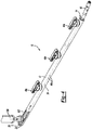
Figure 1 is a side perspective view of a mold for forming a coated IM nail constructed in accordance to one example of the present teachings; -
Figure 2 is a partial cross-sectional view of the mold taken along lines 2-2 ofFigure 1 ; -
Figure 3 is an end perspective view of the mold ofFigure 1 ; -
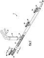
Figure 4 is a side perspective view of the mold ofFigure 1 and shown with an IM nail inserted into the tubular member and a flowable material delivery device threadably coupled to a first port according to one example of the present disclosure; -
Figure 5 is a side perspective view of the mold ofFigure 4 and shown with the flowable material delivery device moved to an adjacent threaded port subsequent to delivery of a sufficient amount of flowable material into the first port; -
Figure 6 is a cross-sectional view taken along lines 6-6 ofFigure 5 taken through a set of nibs extending from protrusions on an inner surface of the tubular member; -
Figure 7 is a cross-sectional view taken along lines 7-7 of the tubular member taken along a section of the tubular member without nibs; -
Figure 8 is a side perspective view of a mold constructed in accordance to additional features of the present disclosure and formed of wire-reinforced silicone; and -
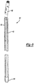
Figure 9 is a side perspective view of a coated IM nail subsequent to removal of the mold according to one example of the present disclosure and shown having a protective membrane cover disposed around a distal end thereof to inhibit flowable material from entering the IM nail. - Corresponding reference numerals indicate corresponding parts throughout the several views of the drawings.
- The following description of technology is merely exemplary in nature of the subject matter, manufacture and use of one or more disclosures, and is not intended to limit the scope, application, or uses of any specific disclosure claimed in this application or in such other applications as may be filed claiming priority to this application, or patents issuing therefrom. Moreover, although the following description and illustrations refer specifically to a mold and related method for coating an IM nail, it will be understood that the molds and related methods disclosed herein may be applied to other implants. In addition, it will be understood that the terms "nail" and "rod" are used herein interchangeably to refer to the same or similar components. Furthermore, while the molds and related methods disclosed herein are specifically directed toward fabrication of antibiotic-loaded, cement-coated rods, the molds and methods disclosed herein may also be adapted to introduce other flowable material onto a surface of a prosthetic implant. Moreover, the molds and related methods disclosed herein may be used to create antibiotic-loaded, cement-coated implants applicable for use with other bones in the body. Therefore, it will be understood that the present description and the claims are applicable to any appropriate bone in the body. A non-limiting discussion of terms and phrases intended to aid understanding of the present technology is provided at the end of the specification.
- With initial reference to
Fig. 1 , a mold that may be used to form a coated intramedullary (IM) nail according to one example of the present disclosure is shown and generally identified atreference numeral 10. Themold 10 can include atubular member 12 having aninsertion end 14 and anopposite end 16. In the example shown, theinsertion end 14 defines an opening whereas theopposite end 16 provides aclosed end 22. In the example shown, theclosed end 22 can have a generally convexouter surface 24. Thetubular member 12 can extend generally along alongitudinal axis 30. - With continued reference to
Fig. 1 and additional reference now toFig. 2 , thetubular member 12 can have asidewall 34 that has anouter surface 36 and aninner surface 38. In the example shown, thesidewall 34 is cylindrical however other cross-sections are contemplated. Thesidewall 34 can generally extend along thelongitudinal axis 30. Thesidewall 34 defines a plurality ofinlet ports boss structures outer surface 36 on thesidewall 34. Eachboss structure threads inlet port 40a,boss 42a, andthreads 44a can collectively comprise a first threadedinlet port 48a. Similarly, theinlet port 40b,boss 42b, andthreads 44b can collectively define a second threaded inlet port 48b. The inlet port 40c,boss 42c, and threads 44c can collectively comprise a third threadedinlet port 48c. Theinlet port 40d,boss 42d, andthreads 44d can collectively comprise a fourth threadedinlet port 48d. It will be appreciated that while the particulartubular member 12 shown in the examples herein incorporates four threaded inlet ports, additional or fewer threaded inlet ports may be incorporated thereon. Moreover, some or all of the threadedinlet ports respective bosses caps inlet ports - With particular reference now to
Figs. 2 and3 , additional features of thetubular member 12 will be described. A first, second, andthird protrusion inner surface 38 of thesidewall 34. In the example shown, theprotrusions inner surface 38 at radially equidistant intervals. In the example shown, theprotrusions tubular member 12 between the insertion end 14 (Fig. 1 ) and the opposite end 16 (Fig. 1 ). While three protrusions are shown, it is appreciated that additional or fewer protrusions may be incorporated. According to one example, theprotrusions nibs longitudinal axis 30. Eachnib nail engaging surface nail engaging surfaces Fig. 6 ) and offset thenail 60 inwardly along thelongitudinal axis 30 and spaced from a remainder of theprotrusions protrusions Fig. 9 ) in the cement surface of a resulting cement-coated IM nail 60'. Thevent grooves 62 can inhibit pressure build-up during implantation of the cement coated IM nail 60'. - With specific reference now to
Fig. 3 , additional features of thetubular member 12 will be described. A first, second, and third plurality of vent holes orports sidewall 34. In the example shown, each row ofvent ports protrusions vent ports tubular member 12 during advancement of the flowable material within thetubular member 12 as will become appreciated from the following discussion. - The
tubular member 12 can be formed of easily cuttable, transparent or translucent material such as silicone. The material can further be flexible and conducive to cement-releasing. In some examples, the silicone can have a reinforcing structure such as a wire mesh. Thetubular member 12 can be formed in any dimensions to accommodate receipt of an IM nail (or other prosthetic implant) having any given dimension. Furthermore, and as identified above, thetubular member 12 can be cut to length to accommodate an IM nail having any length. - According to another example of the present disclosure, a pull member 80 (
Fig. 3 ) can be incorporated into or adjacent thesidewall 34. Thepull member 80 can extend partially or completely along the length of thesidewall 34 of thetubular member 12. Thepull member 80 can be configured to facilitate removal of thetubular member 12 subsequent to curing of the flowable material against the IM nail. In this regard, thepull member 80 can include a pull structure 82 such as a loop or other easily graspable configuration where a user can pull the pull structure 82 generally away from thelongitudinal axis 30 creating a cut or slit along and through the length of thesidewall 34 of thetubular member 12. Once the slit has been formed along thetubular member 12, the user can easily peel away thetubular member 12 to reveal the coated IM nail 60'. - With particular reference now to
Figs. 4-7 , a method of coating theIM nail 60 according to one example of the present disclosure will be described. According to the present disclosure,multiple molds 10 will be provided having various inner and outer diameters. A user can select anappropriate mold 10 that suits aparticular nail 60 for a given application. It will be understood that the overall length of themold 10 can be modified such as by cutting a length off of theinsertion end 14. - At the outset, the
IM nail 60 can be introduced into thetubular member 12 as shown inFig. 4 . Next, one of the threaded caps, such as 49d, can be removed from its threaded inlet port, such as the threadedinlet port 48d. A flowablematerial delivery device 100 can be coupled to the threadedinlet port 48d. Next, a user can advanceflowable material 102 through theinlet port 40d and into thetubular member 12. In the example shown, the flowablematerial delivery device 100 can include a handle 108 (Fig. 5 ) that can be actuated to influence emission of theflowable material 102 out of thedelivery device 100 and into theinlet port 40d. Other configurations of the flowable material delivery device may be used. Furthermore, it will be appreciated that other connections may be made between the flowablematerial delivery device 100 and the respective inlet ports. For example, a luer lock coupling, a nozzle coupling or other coupling may be employed. - A user can continue to introduce the
flowable material 102 into thetubular member 12 until theflowable material 102 has advanced sufficiently along a portion of thetubular member 12 toward an adjacent inlet port 40c. As thetubular member 12 is formed of a transparent material, a user can observe theflowable material 102 advancing along a length of the tubular member 12 (between theinner surface 38 of thesidewall 34 and the IM nail 60). In one example, a user can stop introduction of theflowable material 102 into thetubular member 12 once theflowable material 102 has advanced substantially, such as about three-fourths of the way, toward the adjacent inlet port 40c. Other examples are contemplated. - Next, a user can remove the flowable
material delivery device 100 from the threadedinlet port 48d and replace thecap 49d onto the threadedinlet port 48d. Thecap 49c can then be removed from the adjacent threadedinlet port 48c. The flowablematerial delivery device 100 can then be coupled to the threadedinlet port 48c. Next, a user can urge theflowable material 102 through the inlet port 40c and into thetubular member 12. Notably, theflowable material 102 can backfill toward the fourth threadedinlet port 48d as well as advance in an opposite direction toward the second threaded inlet port 48b. As can be appreciated, as theflowable material 102 backfills toward the fourth threadedinlet port 48d, the flowable material will spread evenly along theIM nail 60 between the fourth and third threadedinlet ports - The process is repeated for subsequent inlet ports along the length of the
tubular member 12 until theflowable material 102 has been sufficiently coated along the length of theIM nail 60. It will be appreciated that while not necessary, in some examples, theflowable material 102 may extend out of some or all of thevent ports flowable material 102 into thetubular member 12, thevent ports tubular member 12 to accommodate introduction of the flowable material between thetubular member 12 and theIM nail 60. - With reference to
Fig. 8 , a tubular member 12' constructed in accordance to additional features is shown. The tubular member 12' can include a reinforced silicone material. The reinforced silicone material can include awire mesh 104. Other reinforcing structures may be incorporated. - With particular reference to
Fig. 9 , once theflowable material 102 has cured a sufficient amount, thetubular member 12 can be cut away from the coated IM nail 60' and discarded. The resulting coated IM nail 60' can include thelongitudinally extending grooves 62 formed therealong that can accommodate air escape and inhibit pressure build-up during implantation into an IM canal. According to a further example of the disclosure, athin membrane sheath 120 can be incorporated onto an end of theIM nail 60 prior to insertion of theIM nail 60 into thetubular member 12. Thesheath 120 can inhibit introduction of flowable material into theIM nail 60 such as through an exposed cannulation thereon. Additionally or alternatively, a plug or collection of plugs, such as formed by flexible silicone, can be inserted into screw holes or the cannulation of the nail to inhibit introduction of flowable material into theIM nail 60. - The foregoing description of the embodiments has been provided for purposes of illustration and description. It is not intended to be exhaustive or to limit the disclosure. Individual elements or features of a particular embodiment are generally not limited to that particular embodiment, but, where applicable, are interchangeable and can be used in a selected embodiment, even if not specifically shown or described. The same may also be varied in many ways. Such variations are not to be regarded as a departure from the disclosure, and all such modifications are intended to be included within the scope of the disclosure.
- The headings (such as "Introduction" and "Summary") and sub-headings used herein are intended only for general organization of topics within the present disclosure, and are not intended to limit the disclosure of the technology or any aspect thereof. In particular, subject matter disclosed in the "Introduction" may include novel technology and may not constitute a recitation of prior art. Subject matter disclosed in the "Summary" is not an exhaustive or complete disclosure of the entire scope of the technology or any embodiments thereof. Classification or discussion of a material within a section of this specification as having a particular utility is made for convenience, and no inference should be drawn that the material must necessarily or solely function in accordance with its classification herein when it is used in any given composition.
- The description and specific examples, while indicating embodiments of the technology, are intended for purposes of illustration only and are not intended to limit the scope of the technology. Moreover, recitation of multiple embodiments having stated features is not intended to exclude other embodiments having additional features, or other embodiments incorporating different combinations of the stated features. Specific examples are provided for illustrative purposes of how to make and use the compositions and methods of this technology and, unless explicitly stated otherwise, are not intended to be a representation that given embodiments of this technology have, or have not, been made or tested.
- As used herein, the words "desire" or "desirable" refer to embodiments of the technology that afford certain benefits, under certain circumstances. However, other embodiments may also be desirable, under the same or other circumstances. Furthermore, the recitation of one or more desired embodiments does not imply that other embodiments are not useful, and is not intended to exclude other embodiments from the scope of the technology.
- As used herein, the word "include," and its variants, is intended to be non-limiting, such that recitation of items in a list is not to the exclusion of other like items that may also be useful in the materials, compositions, devices, and methods of this technology. Similarly, the terms "can" and "may" and their variants are intended to be non-limiting, such that recitation that an embodiment can or may comprise certain elements or features does not exclude other embodiments of the present technology that do not contain those elements or features.
- Although the open-ended term "comprising," as a synonym of non-restrictive terms such as including, containing, or having, is used herein to describe and claim embodiments of the present technology, embodiments may alternatively be described using more limiting terms such as "consisting of" or "consisting essentially of." Thus, for any given embodiment reciting materials, components or process steps, the present technology also specifically includes embodiments consisting of, or consisting essentially of, such materials, components or processes excluding additional materials, components or processes (for consisting of) and excluding additional materials, components or processes affecting the significant properties of the embodiment (for consisting essentially of), even though such additional materials, components or processes are not explicitly recited in this application. For example, recitation of a composition or process reciting elements A, B and C specifically envisions embodiments consisting of, and consisting essentially of, A, B and C, excluding an element D that may be recited in the art, even though element D is not explicitly described as being excluded herein.
- When an element or layer is referred to as being "on", "engaged to", "connected to" or "coupled to" another element or layer, it may be directly on, engaged, connected or coupled to the other element or layer, or intervening elements or layers may be present. In contrast, when an element is referred to as being "directly on", "directly engaged to", "directly connected to" or "directly coupled to" another element or layer, there may be no intervening elements or layers present. Other words used to describe the relationship between elements should be interpreted in a like fashion (e.g., "between" versus "directly between," "adjacent" versus "directly adjacent," etc.). As used herein, the term "and/or" includes any and all combinations of one or more of the associated listed items.
Claims (9)
- A method of coating an intramedullary (IM) nail with flowable material, the method comprising:- advancing the IM nail into a tubular member from an insertion end of the tubular member toward an opposite end of the tubular member;- advancing flowable material through a first port defined through a sidewall at a first location on the tubular member;- advancing flowable material through a second port defined through the sidewall at a second location, distinct from the first location, on the tubular member; and- subsequent to curing of the flowable material, removing the tubular member from the IM nail having the cured flowable material thereon.
- The method of claim 1 wherein advancing the IM nail further comprises slidably translating the IM nail along at least two longitudinally extending protrusions formed on an inner cylindrical surface of the sidewall.
- The method of claim 2 wherein advancing the IM nail comprises advancing the IM nail into the tubular member until a distal end of the IM nail engages a concave surface at the opposite end of the tubular member.
- The method of claim 1 further comprising coupling a flowable material delivery device to a boss formed on the tubular member proximate to the first port.
- The method of claim 4 wherein coupling the flowable material delivery device to the boss comprises one of threadably coupling, luer lock coupling, and nozzle coupling the flowable material delivery device to the tubular member.
- The method of claim 1, further comprising:- observing the flowable material advancing within the tubular member; and- stopping the advancing of the flowable material through the first port based on the flowable material advancing substantially toward the second port.
- The method of claim 1 wherein removing the tubular member comprises cutting the tubular member away from the coated IM nail.
- The method of claim 1 wherein removing the tubular member comprises pulling a pull member disposed on the tubular member causing a slit to be formed along the tubular member.
- The method of claim 1, further comprising disposing a sheath onto an end of the IM nail prior to the advancing of the IM nail into the tubular member.
Applications Claiming Priority (3)
| Application Number | Priority Date | Filing Date | Title |
|---|---|---|---|
| US13/547,331 US9017055B2 (en) | 2012-07-12 | 2012-07-12 | Device for coating intramedullary rods with cement |
| PCT/US2013/050026 WO2014011843A2 (en) | 2012-07-12 | 2013-07-11 | Device for coating intramedullary rods with cement |
| EP13739915.0A EP2872307B1 (en) | 2012-07-12 | 2013-07-11 | Device and method for coating intramedullary rods with cement |
Related Parent Applications (1)
| Application Number | Title | Priority Date | Filing Date |
|---|---|---|---|
| EP13739915.0A Division EP2872307B1 (en) | 2012-07-12 | 2013-07-11 | Device and method for coating intramedullary rods with cement |
Publications (2)
| Publication Number | Publication Date |
|---|---|
| EP3175963A1 true EP3175963A1 (en) | 2017-06-07 |
| EP3175963B1 EP3175963B1 (en) | 2018-09-19 |
Family
ID=48833082
Family Applications (2)
| Application Number | Title | Priority Date | Filing Date |
|---|---|---|---|
| EP17150540.7A Not-in-force EP3175963B1 (en) | 2012-07-12 | 2013-07-11 | Method of coating an intramedullary nail with flowable material |
| EP13739915.0A Not-in-force EP2872307B1 (en) | 2012-07-12 | 2013-07-11 | Device and method for coating intramedullary rods with cement |
Family Applications After (1)
| Application Number | Title | Priority Date | Filing Date |
|---|---|---|---|
| EP13739915.0A Not-in-force EP2872307B1 (en) | 2012-07-12 | 2013-07-11 | Device and method for coating intramedullary rods with cement |
Country Status (7)
| Country | Link |
|---|---|
| US (2) | US9017055B2 (en) |
| EP (2) | EP3175963B1 (en) |
| JP (2) | JP6047656B2 (en) |
| CN (2) | CN104520089B (en) |
| AU (2) | AU2013290197B2 (en) |
| ES (1) | ES2631328T3 (en) |
| WO (1) | WO2014011843A2 (en) |
Families Citing this family (11)
| Publication number | Priority date | Publication date | Assignee | Title |
|---|---|---|---|---|
| US9017055B2 (en) | 2012-07-12 | 2015-04-28 | Biomet Manufacturing, Llc | Device for coating intramedullary rods with cement |
| DE102013005414A1 (en) * | 2013-03-28 | 2014-10-02 | Dietmar Wolter | Osteosynthesis system for the multidirectional, angularly stable treatment of fractures of long bones including an intramedullary nail and bone screws |
| EP3735193A1 (en) | 2018-01-03 | 2020-11-11 | GLW, Inc. | Hybrid cannulated orthopedic screws |
| EP3740145B1 (en) | 2018-01-15 | 2025-06-04 | GLW, Inc. | Hybrid intramedullary rods |
| EP4385433B1 (en) | 2019-03-18 | 2026-01-14 | GLW, Inc. | Hybrid bone plate |
| CN111150475A (en) * | 2020-01-15 | 2020-05-15 | 中国人民解放军第四军医大学 | A kind of bone cement intramedullary nail and preparation method thereof |
| US20220305708A1 (en) * | 2020-05-05 | 2022-09-29 | Brent Austin McNeely | Cement Spacer Mold System |
| US12186000B2 (en) | 2020-09-04 | 2025-01-07 | DePuy Synthes Products, Inc. | Temporary antimicrobial cement spacer, assembly, kit, and method of manufacture |
| EP4319666B1 (en) | 2021-04-09 | 2025-06-11 | GLW, Inc. | Hybrid bone plates and associated manufacturing processes |
| USD969323S1 (en) | 2022-06-21 | 2022-11-08 | Mc Innovation Llc | Bone spacer mold system |
| WO2024187067A2 (en) * | 2023-03-08 | 2024-09-12 | Genesis Medical Devices Llc | Apparatus and method for uniform coating of implants with antibiotic cement |
Citations (2)
| Publication number | Priority date | Publication date | Assignee | Title |
|---|---|---|---|---|
| WO2010088531A2 (en) * | 2009-01-29 | 2010-08-05 | Smith & Nephew, Inc. | Low temperature encapsulate welding |
| US20120089148A1 (en) * | 2010-10-12 | 2012-04-12 | Rahul Vaidya | Apparatus and method for forming an antibiotic impregnated bone cement intramedullary nail |
Family Cites Families (24)
| Publication number | Priority date | Publication date | Assignee | Title |
|---|---|---|---|---|
| JPH03223586A (en) * | 1990-01-29 | 1991-10-02 | Natl House Ind Co Ltd | Plaster covered pipe |
| US5098434A (en) | 1990-11-28 | 1992-03-24 | Boehringer Mannheim Corporation | Porous coated bone screw |
| CA2031571A1 (en) | 1990-12-05 | 1992-06-06 | The University Of British Columbia | Antibiotic loaded joint prosthesis |
| US5258098A (en) | 1991-06-17 | 1993-11-02 | Cycam, Inc. | Method of production of a surface adapted to promote adhesion |
| US5360448A (en) | 1991-10-07 | 1994-11-01 | Thramann Jeffrey J | Porous-coated bone screw for securing prosthesis |
| US5433718A (en) | 1992-08-20 | 1995-07-18 | Brinker; Mark | Antibiotic eluding intramedullary nail apparatus |
| US5716358A (en) | 1994-12-02 | 1998-02-10 | Johnson & Johnson Professional, Inc. | Directional bone fixation device |
| US5489306A (en) | 1995-01-03 | 1996-02-06 | Gorski; Jerrold M. | Graduated porosity implant for fibro-osseous integration |
| SE9701647D0 (en) | 1997-04-30 | 1997-04-30 | Nobel Biocare Ab | Calcium-phonsphate coated implant element |
| US6361731B1 (en) * | 1998-07-15 | 2002-03-26 | Biomet, Inc. | Method of forming a temporary implant |
| ATE353609T1 (en) | 1999-01-12 | 2007-03-15 | Lipat Consulting Ag | SURFACE STRUCTURE FOR AN ENOSSAL IMPLANT |
| US6183255B1 (en) | 2000-03-27 | 2001-02-06 | Yoshiki Oshida | Titanium material implants |
| DE102004009429A1 (en) * | 2004-02-24 | 2005-09-22 | Biedermann Motech Gmbh | Bone anchoring element |
| US9452001B2 (en) | 2005-02-22 | 2016-09-27 | Tecres S.P.A. | Disposable device for treatment of infections of human limbs |
| ITVI20050049A1 (en) | 2005-02-22 | 2006-08-23 | Tecres Spa | DISPOSABLE DEVICE FOR THE TREATMENT OF INFECTION OF ARTS OF THE HUMAN BODY, PARTICULARLY OF ARTS WITH LONG BONES |
| US8900620B2 (en) | 2005-10-13 | 2014-12-02 | DePuy Synthes Products, LLC | Drug-impregnated encasement |
| ES2595308T3 (en) * | 2007-06-22 | 2016-12-29 | Epix Orthopaedics, Inc. | Intramedullary rod with pivoting bra |
| GB0718417D0 (en) * | 2007-09-21 | 2007-10-31 | Depuy Int Ltd | Intramedullary rod instrument |
| US7789646B2 (en) * | 2007-12-07 | 2010-09-07 | Zimmer Orthopaedic Surgical Products, Inc. | Spacer mold and methods therefor |
| US7637729B2 (en) | 2007-12-13 | 2009-12-29 | Biomet Manufacturing Corp. | Modular articulating cement spacer mold |
| CN101659130B (en) * | 2009-09-17 | 2011-08-17 | 周志海 | Molding mold of interlocking intramedullary nail |
| KR101830799B1 (en) * | 2011-08-22 | 2018-02-22 | 삼성전자 주식회사 | Antenna device of a mobile terminal |
| US8961844B2 (en) | 2012-07-10 | 2015-02-24 | Nike, Inc. | Bead foam compression molding method for low density product |
| US9017055B2 (en) | 2012-07-12 | 2015-04-28 | Biomet Manufacturing, Llc | Device for coating intramedullary rods with cement |
-
2012
- 2012-07-12 US US13/547,331 patent/US9017055B2/en active Active
-
2013
- 2013-07-11 CN CN201380036818.2A patent/CN104520089B/en not_active Expired - Fee Related
- 2013-07-11 WO PCT/US2013/050026 patent/WO2014011843A2/en not_active Ceased
- 2013-07-11 AU AU2013290197A patent/AU2013290197B2/en not_active Ceased
- 2013-07-11 ES ES13739915.0T patent/ES2631328T3/en active Active
- 2013-07-11 EP EP17150540.7A patent/EP3175963B1/en not_active Not-in-force
- 2013-07-11 CN CN201710600108.8A patent/CN107521014B/en not_active Expired - Fee Related
- 2013-07-11 EP EP13739915.0A patent/EP2872307B1/en not_active Not-in-force
- 2013-07-11 JP JP2015521798A patent/JP6047656B2/en not_active Expired - Fee Related
-
2015
- 2015-04-20 US US14/691,070 patent/US9440379B2/en active Active
-
2016
- 2016-11-21 JP JP2016226221A patent/JP6293243B2/en not_active Expired - Fee Related
-
2017
- 2017-01-31 AU AU2017200647A patent/AU2017200647B2/en not_active Ceased
Patent Citations (2)
| Publication number | Priority date | Publication date | Assignee | Title |
|---|---|---|---|---|
| WO2010088531A2 (en) * | 2009-01-29 | 2010-08-05 | Smith & Nephew, Inc. | Low temperature encapsulate welding |
| US20120089148A1 (en) * | 2010-10-12 | 2012-04-12 | Rahul Vaidya | Apparatus and method for forming an antibiotic impregnated bone cement intramedullary nail |
Also Published As
| Publication number | Publication date |
|---|---|
| JP6047656B2 (en) | 2016-12-21 |
| ES2631328T3 (en) | 2017-08-30 |
| EP2872307A2 (en) | 2015-05-20 |
| AU2013290197B2 (en) | 2016-11-24 |
| US9440379B2 (en) | 2016-09-13 |
| AU2017200647B2 (en) | 2017-06-08 |
| WO2014011843A3 (en) | 2014-02-27 |
| EP2872307B1 (en) | 2017-01-18 |
| US20140017391A1 (en) | 2014-01-16 |
| AU2013290197A1 (en) | 2015-01-22 |
| CN104520089B (en) | 2017-08-18 |
| CN104520089A (en) | 2015-04-15 |
| US20150321389A1 (en) | 2015-11-12 |
| CN107521014A (en) | 2017-12-29 |
| AU2017200647A1 (en) | 2017-02-23 |
| EP3175963B1 (en) | 2018-09-19 |
| JP2015522359A (en) | 2015-08-06 |
| US9017055B2 (en) | 2015-04-28 |
| WO2014011843A2 (en) | 2014-01-16 |
| JP2017094087A (en) | 2017-06-01 |
| CN107521014B (en) | 2019-11-22 |
| JP6293243B2 (en) | 2018-03-14 |
Similar Documents
| Publication | Publication Date | Title |
|---|---|---|
| AU2017200647B2 (en) | Device for coating intramedullary rods with cement | |
| US10744689B2 (en) | Method and device for producing temporary knee joint spacers with stems of various sizes | |
| US12186000B2 (en) | Temporary antimicrobial cement spacer, assembly, kit, and method of manufacture | |
| EP3165193B1 (en) | Handheld dental tool | |
| EP3364897B1 (en) | Sterilizable disposable surgical instrument for bone fusion surgery | |
| DE202010012260U1 (en) | Cannula and cannula device for implanting an implant | |
| US11096732B2 (en) | Hybrid bone fixation wire | |
| JP6521999B2 (en) | Device for removing bone cement from a bone cavity | |
| US12186961B2 (en) | Method of forming a reusable surgical implement | |
| DE202012002829U1 (en) | Device for the application of bone cement |
Legal Events
| Date | Code | Title | Description |
|---|---|---|---|
| AC | Divisional application: reference to earlier application |
Ref document number: 2872307 Country of ref document: EP Kind code of ref document: P |
|
| AK | Designated contracting states |
Kind code of ref document: A1 Designated state(s): AL AT BE BG CH CY CZ DE DK EE ES FI FR GB GR HR HU IE IS IT LI LT LU LV MC MK MT NL NO PL PT RO RS SE SI SK SM TR |
|
| PUAI | Public reference made under article 153(3) epc to a published international application that has entered the european phase |
Free format text: ORIGINAL CODE: 0009012 |
|
| STAA | Information on the status of an ep patent application or granted ep patent |
Free format text: STATUS: THE APPLICATION HAS BEEN PUBLISHED |
|
| STAA | Information on the status of an ep patent application or granted ep patent |
Free format text: STATUS: REQUEST FOR EXAMINATION WAS MADE |
|
| 17P | Request for examination filed |
Effective date: 20171120 |
|
| RBV | Designated contracting states (corrected) |
Designated state(s): AL AT BE BG CH CY CZ DE DK EE ES FI FR GB GR HR HU IE IS IT LI LT LU LV MC MK MT NL NO PL PT RO RS SE SI SK SM TR |
|
| RIC1 | Information provided on ipc code assigned before grant |
Ipc: A61B 17/00 20060101ALN20180221BHEP Ipc: B29C 39/24 20060101ALI20180221BHEP Ipc: B29C 33/00 20060101ALN20180221BHEP Ipc: B29C 39/10 20060101AFI20180221BHEP Ipc: B29C 39/26 20060101ALI20180221BHEP Ipc: A61B 17/72 20060101ALN20180221BHEP |
|
| GRAP | Despatch of communication of intention to grant a patent |
Free format text: ORIGINAL CODE: EPIDOSNIGR1 |
|
| STAA | Information on the status of an ep patent application or granted ep patent |
Free format text: STATUS: GRANT OF PATENT IS INTENDED |
|
| RIC1 | Information provided on ipc code assigned before grant |
Ipc: B29C 39/10 20060101AFI20180313BHEP Ipc: A61B 17/00 20060101ALN20180313BHEP Ipc: B29C 39/26 20060101ALI20180313BHEP Ipc: B29C 33/00 20060101ALN20180313BHEP Ipc: A61B 17/72 20060101ALN20180313BHEP Ipc: B29C 39/24 20060101ALI20180313BHEP |
|
| INTG | Intention to grant announced |
Effective date: 20180404 |
|
| GRAS | Grant fee paid |
Free format text: ORIGINAL CODE: EPIDOSNIGR3 |
|
| GRAA | (expected) grant |
Free format text: ORIGINAL CODE: 0009210 |
|
| STAA | Information on the status of an ep patent application or granted ep patent |
Free format text: STATUS: THE PATENT HAS BEEN GRANTED |
|
| AC | Divisional application: reference to earlier application |
Ref document number: 2872307 Country of ref document: EP Kind code of ref document: P |
|
| AK | Designated contracting states |
Kind code of ref document: B1 Designated state(s): AL AT BE BG CH CY CZ DE DK EE ES FI FR GB GR HR HU IE IS IT LI LT LU LV MC MK MT NL NO PL PT RO RS SE SI SK SM TR |
|
| REG | Reference to a national code |
Ref country code: GB Ref legal event code: FG4D |
|
| REG | Reference to a national code |
Ref country code: CH Ref legal event code: EP |
|
| REG | Reference to a national code |
Ref country code: AT Ref legal event code: REF Ref document number: 1042728 Country of ref document: AT Kind code of ref document: T Effective date: 20181015 |
|
| REG | Reference to a national code |
Ref country code: IE Ref legal event code: FG4D |
|
| REG | Reference to a national code |
Ref country code: DE Ref legal event code: R096 Ref document number: 602013044102 Country of ref document: DE |
|
| REG | Reference to a national code |
Ref country code: NL Ref legal event code: MP Effective date: 20180919 |
|
| PG25 | Lapsed in a contracting state [announced via postgrant information from national office to epo] |
Ref country code: SE Free format text: LAPSE BECAUSE OF FAILURE TO SUBMIT A TRANSLATION OF THE DESCRIPTION OR TO PAY THE FEE WITHIN THE PRESCRIBED TIME-LIMIT Effective date: 20180919 Ref country code: RS Free format text: LAPSE BECAUSE OF FAILURE TO SUBMIT A TRANSLATION OF THE DESCRIPTION OR TO PAY THE FEE WITHIN THE PRESCRIBED TIME-LIMIT Effective date: 20180919 Ref country code: LT Free format text: LAPSE BECAUSE OF FAILURE TO SUBMIT A TRANSLATION OF THE DESCRIPTION OR TO PAY THE FEE WITHIN THE PRESCRIBED TIME-LIMIT Effective date: 20180919 Ref country code: GR Free format text: LAPSE BECAUSE OF FAILURE TO SUBMIT A TRANSLATION OF THE DESCRIPTION OR TO PAY THE FEE WITHIN THE PRESCRIBED TIME-LIMIT Effective date: 20181220 Ref country code: FI Free format text: LAPSE BECAUSE OF FAILURE TO SUBMIT A TRANSLATION OF THE DESCRIPTION OR TO PAY THE FEE WITHIN THE PRESCRIBED TIME-LIMIT Effective date: 20180919 Ref country code: BG Free format text: LAPSE BECAUSE OF FAILURE TO SUBMIT A TRANSLATION OF THE DESCRIPTION OR TO PAY THE FEE WITHIN THE PRESCRIBED TIME-LIMIT Effective date: 20181219 Ref country code: NO Free format text: LAPSE BECAUSE OF FAILURE TO SUBMIT A TRANSLATION OF THE DESCRIPTION OR TO PAY THE FEE WITHIN THE PRESCRIBED TIME-LIMIT Effective date: 20181219 |
|
| REG | Reference to a national code |
Ref country code: LT Ref legal event code: MG4D |
|
| PG25 | Lapsed in a contracting state [announced via postgrant information from national office to epo] |
Ref country code: HR Free format text: LAPSE BECAUSE OF FAILURE TO SUBMIT A TRANSLATION OF THE DESCRIPTION OR TO PAY THE FEE WITHIN THE PRESCRIBED TIME-LIMIT Effective date: 20180919 Ref country code: AL Free format text: LAPSE BECAUSE OF FAILURE TO SUBMIT A TRANSLATION OF THE DESCRIPTION OR TO PAY THE FEE WITHIN THE PRESCRIBED TIME-LIMIT Effective date: 20180919 Ref country code: LV Free format text: LAPSE BECAUSE OF FAILURE TO SUBMIT A TRANSLATION OF THE DESCRIPTION OR TO PAY THE FEE WITHIN THE PRESCRIBED TIME-LIMIT Effective date: 20180919 |
|
| REG | Reference to a national code |
Ref country code: AT Ref legal event code: MK05 Ref document number: 1042728 Country of ref document: AT Kind code of ref document: T Effective date: 20180919 |
|
| PG25 | Lapsed in a contracting state [announced via postgrant information from national office to epo] |
Ref country code: NL Free format text: LAPSE BECAUSE OF FAILURE TO SUBMIT A TRANSLATION OF THE DESCRIPTION OR TO PAY THE FEE WITHIN THE PRESCRIBED TIME-LIMIT Effective date: 20180919 Ref country code: AT Free format text: LAPSE BECAUSE OF FAILURE TO SUBMIT A TRANSLATION OF THE DESCRIPTION OR TO PAY THE FEE WITHIN THE PRESCRIBED TIME-LIMIT Effective date: 20180919 Ref country code: PL Free format text: LAPSE BECAUSE OF FAILURE TO SUBMIT A TRANSLATION OF THE DESCRIPTION OR TO PAY THE FEE WITHIN THE PRESCRIBED TIME-LIMIT Effective date: 20180919 Ref country code: EE Free format text: LAPSE BECAUSE OF FAILURE TO SUBMIT A TRANSLATION OF THE DESCRIPTION OR TO PAY THE FEE WITHIN THE PRESCRIBED TIME-LIMIT Effective date: 20180919 Ref country code: ES Free format text: LAPSE BECAUSE OF FAILURE TO SUBMIT A TRANSLATION OF THE DESCRIPTION OR TO PAY THE FEE WITHIN THE PRESCRIBED TIME-LIMIT Effective date: 20180919 Ref country code: RO Free format text: LAPSE BECAUSE OF FAILURE TO SUBMIT A TRANSLATION OF THE DESCRIPTION OR TO PAY THE FEE WITHIN THE PRESCRIBED TIME-LIMIT Effective date: 20180919 Ref country code: CZ Free format text: LAPSE BECAUSE OF FAILURE TO SUBMIT A TRANSLATION OF THE DESCRIPTION OR TO PAY THE FEE WITHIN THE PRESCRIBED TIME-LIMIT Effective date: 20180919 Ref country code: IT Free format text: LAPSE BECAUSE OF FAILURE TO SUBMIT A TRANSLATION OF THE DESCRIPTION OR TO PAY THE FEE WITHIN THE PRESCRIBED TIME-LIMIT Effective date: 20180919 Ref country code: IS Free format text: LAPSE BECAUSE OF FAILURE TO SUBMIT A TRANSLATION OF THE DESCRIPTION OR TO PAY THE FEE WITHIN THE PRESCRIBED TIME-LIMIT Effective date: 20190119 |
|
| PG25 | Lapsed in a contracting state [announced via postgrant information from national office to epo] |
Ref country code: PT Free format text: LAPSE BECAUSE OF FAILURE TO SUBMIT A TRANSLATION OF THE DESCRIPTION OR TO PAY THE FEE WITHIN THE PRESCRIBED TIME-LIMIT Effective date: 20190119 Ref country code: SM Free format text: LAPSE BECAUSE OF FAILURE TO SUBMIT A TRANSLATION OF THE DESCRIPTION OR TO PAY THE FEE WITHIN THE PRESCRIBED TIME-LIMIT Effective date: 20180919 Ref country code: SK Free format text: LAPSE BECAUSE OF FAILURE TO SUBMIT A TRANSLATION OF THE DESCRIPTION OR TO PAY THE FEE WITHIN THE PRESCRIBED TIME-LIMIT Effective date: 20180919 |
|
| REG | Reference to a national code |
Ref country code: DE Ref legal event code: R097 Ref document number: 602013044102 Country of ref document: DE |
|
| PLBE | No opposition filed within time limit |
Free format text: ORIGINAL CODE: 0009261 |
|
| STAA | Information on the status of an ep patent application or granted ep patent |
Free format text: STATUS: NO OPPOSITION FILED WITHIN TIME LIMIT |
|
| PG25 | Lapsed in a contracting state [announced via postgrant information from national office to epo] |
Ref country code: DK Free format text: LAPSE BECAUSE OF FAILURE TO SUBMIT A TRANSLATION OF THE DESCRIPTION OR TO PAY THE FEE WITHIN THE PRESCRIBED TIME-LIMIT Effective date: 20180919 |
|
| 26N | No opposition filed |
Effective date: 20190620 |
|
| PG25 | Lapsed in a contracting state [announced via postgrant information from national office to epo] |
Ref country code: SI Free format text: LAPSE BECAUSE OF FAILURE TO SUBMIT A TRANSLATION OF THE DESCRIPTION OR TO PAY THE FEE WITHIN THE PRESCRIBED TIME-LIMIT Effective date: 20180919 |
|
| PG25 | Lapsed in a contracting state [announced via postgrant information from national office to epo] |
Ref country code: MC Free format text: LAPSE BECAUSE OF FAILURE TO SUBMIT A TRANSLATION OF THE DESCRIPTION OR TO PAY THE FEE WITHIN THE PRESCRIBED TIME-LIMIT Effective date: 20180919 |
|
| REG | Reference to a national code |
Ref country code: CH Ref legal event code: PL |
|
| PG25 | Lapsed in a contracting state [announced via postgrant information from national office to epo] |
Ref country code: TR Free format text: LAPSE BECAUSE OF FAILURE TO SUBMIT A TRANSLATION OF THE DESCRIPTION OR TO PAY THE FEE WITHIN THE PRESCRIBED TIME-LIMIT Effective date: 20180919 |
|
| REG | Reference to a national code |
Ref country code: BE Ref legal event code: MM Effective date: 20190731 |
|
| PG25 | Lapsed in a contracting state [announced via postgrant information from national office to epo] |
Ref country code: LU Free format text: LAPSE BECAUSE OF NON-PAYMENT OF DUE FEES Effective date: 20190711 Ref country code: LI Free format text: LAPSE BECAUSE OF NON-PAYMENT OF DUE FEES Effective date: 20190731 Ref country code: CH Free format text: LAPSE BECAUSE OF NON-PAYMENT OF DUE FEES Effective date: 20190731 Ref country code: BE Free format text: LAPSE BECAUSE OF NON-PAYMENT OF DUE FEES Effective date: 20190731 |
|
| PG25 | Lapsed in a contracting state [announced via postgrant information from national office to epo] |
Ref country code: IE Free format text: LAPSE BECAUSE OF NON-PAYMENT OF DUE FEES Effective date: 20190711 |
|
| PGFP | Annual fee paid to national office [announced via postgrant information from national office to epo] |
Ref country code: FR Payment date: 20200615 Year of fee payment: 8 |
|
| PGFP | Annual fee paid to national office [announced via postgrant information from national office to epo] |
Ref country code: GB Payment date: 20200615 Year of fee payment: 8 |
|
| PGFP | Annual fee paid to national office [announced via postgrant information from national office to epo] |
Ref country code: DE Payment date: 20200611 Year of fee payment: 8 |
|
| PG25 | Lapsed in a contracting state [announced via postgrant information from national office to epo] |
Ref country code: CY Free format text: LAPSE BECAUSE OF FAILURE TO SUBMIT A TRANSLATION OF THE DESCRIPTION OR TO PAY THE FEE WITHIN THE PRESCRIBED TIME-LIMIT Effective date: 20180919 |
|
| PG25 | Lapsed in a contracting state [announced via postgrant information from national office to epo] |
Ref country code: MT Free format text: LAPSE BECAUSE OF FAILURE TO SUBMIT A TRANSLATION OF THE DESCRIPTION OR TO PAY THE FEE WITHIN THE PRESCRIBED TIME-LIMIT Effective date: 20180919 Ref country code: HU Free format text: LAPSE BECAUSE OF FAILURE TO SUBMIT A TRANSLATION OF THE DESCRIPTION OR TO PAY THE FEE WITHIN THE PRESCRIBED TIME-LIMIT; INVALID AB INITIO Effective date: 20130711 |
|
| REG | Reference to a national code |
Ref country code: DE Ref legal event code: R119 Ref document number: 602013044102 Country of ref document: DE |
|
| GBPC | Gb: european patent ceased through non-payment of renewal fee |
Effective date: 20210711 |
|
| PG25 | Lapsed in a contracting state [announced via postgrant information from national office to epo] |
Ref country code: GB Free format text: LAPSE BECAUSE OF NON-PAYMENT OF DUE FEES Effective date: 20210711 Ref country code: DE Free format text: LAPSE BECAUSE OF NON-PAYMENT OF DUE FEES Effective date: 20220201 |
|
| PG25 | Lapsed in a contracting state [announced via postgrant information from national office to epo] |
Ref country code: FR Free format text: LAPSE BECAUSE OF NON-PAYMENT OF DUE FEES Effective date: 20210731 |
|
| PG25 | Lapsed in a contracting state [announced via postgrant information from national office to epo] |
Ref country code: MK Free format text: LAPSE BECAUSE OF FAILURE TO SUBMIT A TRANSLATION OF THE DESCRIPTION OR TO PAY THE FEE WITHIN THE PRESCRIBED TIME-LIMIT Effective date: 20180919 |
|
| P01 | Opt-out of the competence of the unified patent court (upc) registered |
Effective date: 20230526 |