EP3165193B1 - Handheld dental tool - Google Patents
Handheld dental tool Download PDFInfo
- Publication number
- EP3165193B1 EP3165193B1 EP15193647.3A EP15193647A EP3165193B1 EP 3165193 B1 EP3165193 B1 EP 3165193B1 EP 15193647 A EP15193647 A EP 15193647A EP 3165193 B1 EP3165193 B1 EP 3165193B1
- Authority
- EP
- European Patent Office
- Prior art keywords
- tip
- modelling
- coating
- dental tool
- tool according
- Prior art date
- Legal status (The legal status is an assumption and is not a legal conclusion. Google has not performed a legal analysis and makes no representation as to the accuracy of the status listed.)
- Active
Links
- 238000000576 coating method Methods 0.000 claims description 59
- 239000011248 coating agent Substances 0.000 claims description 58
- 230000008878 coupling Effects 0.000 claims description 33
- 238000010168 coupling process Methods 0.000 claims description 33
- 238000005859 coupling reaction Methods 0.000 claims description 33
- 239000000463 material Substances 0.000 claims description 26
- 238000003825 pressing Methods 0.000 claims description 5
- 230000007423 decrease Effects 0.000 claims description 4
- 230000014759 maintenance of location Effects 0.000 claims description 2
- 230000007704 transition Effects 0.000 claims 1
- 239000011162 core material Substances 0.000 description 26
- 239000000806 elastomer Substances 0.000 description 9
- 229920001971 elastomer Polymers 0.000 description 9
- 239000010410 layer Substances 0.000 description 6
- 239000002131 composite material Substances 0.000 description 5
- 230000002349 favourable effect Effects 0.000 description 5
- 239000011159 matrix material Substances 0.000 description 5
- 239000000243 solution Substances 0.000 description 5
- 239000004033 plastic Substances 0.000 description 4
- 229920003023 plastic Polymers 0.000 description 4
- 230000009467 reduction Effects 0.000 description 4
- 230000008901 benefit Effects 0.000 description 3
- 230000000694 effects Effects 0.000 description 3
- 239000006260 foam Substances 0.000 description 3
- 238000000034 method Methods 0.000 description 3
- -1 polyethylene Polymers 0.000 description 3
- 239000004698 Polyethylene Substances 0.000 description 2
- 229910000831 Steel Inorganic materials 0.000 description 2
- 239000000853 adhesive Substances 0.000 description 2
- 230000001070 adhesive effect Effects 0.000 description 2
- 210000003484 anatomy Anatomy 0.000 description 2
- 230000015572 biosynthetic process Effects 0.000 description 2
- 238000002347 injection Methods 0.000 description 2
- 239000007924 injection Substances 0.000 description 2
- 238000001746 injection moulding Methods 0.000 description 2
- 229920000573 polyethylene Polymers 0.000 description 2
- 230000008569 process Effects 0.000 description 2
- 230000003068 static effect Effects 0.000 description 2
- 239000010959 steel Substances 0.000 description 2
- 206010003497 Asphyxia Diseases 0.000 description 1
- 241000196324 Embryophyta Species 0.000 description 1
- 244000261422 Lysimachia clethroides Species 0.000 description 1
- 239000004952 Polyamide Substances 0.000 description 1
- 239000004743 Polypropylene Substances 0.000 description 1
- 230000009471 action Effects 0.000 description 1
- 230000006978 adaptation Effects 0.000 description 1
- 230000001580 bacterial effect Effects 0.000 description 1
- 239000000919 ceramic Substances 0.000 description 1
- 238000004140 cleaning Methods 0.000 description 1
- 238000011109 contamination Methods 0.000 description 1
- 239000005548 dental material Substances 0.000 description 1
- 238000011161 development Methods 0.000 description 1
- 230000018109 developmental process Effects 0.000 description 1
- 238000007598 dipping method Methods 0.000 description 1
- 230000003670 easy-to-clean Effects 0.000 description 1
- 238000005516 engineering process Methods 0.000 description 1
- 238000009499 grossing Methods 0.000 description 1
- 238000004519 manufacturing process Methods 0.000 description 1
- 239000002184 metal Substances 0.000 description 1
- 238000007591 painting process Methods 0.000 description 1
- 229920002647 polyamide Polymers 0.000 description 1
- 229920000098 polyolefin Polymers 0.000 description 1
- 229920001155 polypropylene Polymers 0.000 description 1
- 229920001296 polysiloxane Polymers 0.000 description 1
- 229920001343 polytetrafluoroethylene Polymers 0.000 description 1
- 239000004810 polytetrafluoroethylene Substances 0.000 description 1
- 239000011148 porous material Substances 0.000 description 1
- 230000036316 preload Effects 0.000 description 1
- 229910001220 stainless steel Inorganic materials 0.000 description 1
- 239000010935 stainless steel Substances 0.000 description 1
- 230000001954 sterilising effect Effects 0.000 description 1
- 238000004659 sterilization and disinfection Methods 0.000 description 1
- 238000003860 storage Methods 0.000 description 1
- 239000002344 surface layer Substances 0.000 description 1
Images

Classifications
-
- A—HUMAN NECESSITIES
- A61—MEDICAL OR VETERINARY SCIENCE; HYGIENE
- A61C—DENTISTRY; APPARATUS OR METHODS FOR ORAL OR DENTAL HYGIENE
- A61C3/00—Dental tools or instruments
- A61C3/08—Tooth pluggers or hammers
-
- A—HUMAN NECESSITIES
- A61—MEDICAL OR VETERINARY SCIENCE; HYGIENE
- A61C—DENTISTRY; APPARATUS OR METHODS FOR ORAL OR DENTAL HYGIENE
- A61C1/00—Dental machines for boring or cutting ; General features of dental machines or apparatus, e.g. hand-piece design
- A61C1/08—Machine parts specially adapted for dentistry
- A61C1/12—Angle hand-pieces
-
- A—HUMAN NECESSITIES
- A61—MEDICAL OR VETERINARY SCIENCE; HYGIENE
- A61C—DENTISTRY; APPARATUS OR METHODS FOR ORAL OR DENTAL HYGIENE
- A61C3/00—Dental tools or instruments
-
- A—HUMAN NECESSITIES
- A61—MEDICAL OR VETERINARY SCIENCE; HYGIENE
- A61C—DENTISTRY; APPARATUS OR METHODS FOR ORAL OR DENTAL HYGIENE
- A61C5/00—Filling or capping teeth
- A61C5/50—Implements for filling root canals; Methods or instruments for medication of tooth nerve channels
Definitions
- the invention relates to a dental hand tool, according to the preamble of claim 1.
- Dental hand tools which are also referred to as dental hand instruments, have been known for a long time. Such hand tools are either in one piece or have interchangeable tips, for example modeling tips. The tips are typically bent, for example in the manner of goosenecks, in order to enable the dentist to work on areas that are facing away from the mouth opening of the patient, that is to say on distal areas of teeth or in interdental spaces of molars.
- US20090130628A1 discloses a dental hand-held device with the features of the preamble of claim 1. It goes without saying that the tip must not be lost in the patient's mouth even when pressure is exerted (risk of suffocation). In addition, it is often desirable to be able to exert considerable pressure, so that a secure guidance of the tip via a coupling member is preferred.
- the coupling member there provides a blind hole that is deep and difficult to clean, so that there is no regular autoclaving accumulate bacterial contamination.
- dental hand tools are used, among other things, for stuffing and modeling filling materials.
- a spherical, relatively voluminous tip for example according to the US 6 206 698 A1 .
- a finer tip is favorable for modeling in order to be able to provide the required precision.
- higher shear forces are required, for example for the design of the cusp slopes.
- metallic modeling tips according to the above US 4,552,531 A1 fundamentally proven, although depending on the hardening state of the dental restoration part, the modeling tip is partially glued to the restoration material.
- the invention has for its object to provide a dental hand tool according to the preamble of claim 1, which can be used more universally, in particular both for modeling and for modeling-related activities of the dentist, is easier to handle, but still meets no hygienic concerns.
- a dental hand tool has a modeling tip which mainly consists of a hard material such as a hard plastic.
- the front area of the modeling tip is provided with a coating that is softer than the core of the modeling tip.
- the configuration is spherical, and the front end of the core preferably protrudes from the modeling tip.
- the coating is particularly preferably designed as an elastomer, which has a low surface energy, a low tendency to wet and very good non-stick properties.
- the modeling tip is preferably constructed as a two-component part, which has a rigid core made of a hard carrier plastic with an essentially uniformly thin one Combined layer of a adhesive elastomer.
- the material of the coating is selected so that it has a particularly low surface energy. This is preferably less than 35 mN / m.
- the material is preferably selected so that the tendency to wet is extremely low. Suitable materials include elastomers, silicones, PTFE, but also, for example, a polyolefin. If a foamed material is used as the material for the coating, it is preferred to use a closed-pore foam.
- the surface layer of the foam can also be densified so that it is free of bubbles.
- a configuration with a particularly flexible coating, paired with a fine core tip, is surprisingly particularly favorable when it is a matter of mastering both modeling tasks and filling tasks with the same modeling tip.
- the layer thickness of the coating can be, for example, 0.15 to 0.25 mm. It is even, but decreases at the front end.
- the core protrudes from the coating at the front by approximately 0.25 to 0.75, preferably by 0.5 mm. This enables precise modeling, particularly of composite dental materials.
- this configuration makes it possible to prevent the modeling tip from sticking to the composite, even though there is - albeit slight - contact between the core of the tip and the composite.
- the low layer thickness of the coating also allows the resulting shear forces to be reproduced well, so that even very delicate anatomical tooth structures can be designed.
- the coating according to the invention is not limited to the use of elastomers. Instead of this, for example, a coating made of polytetraflurethylene can also be used, or a coating made of any other material that is significantly softer than the material of the core.
- the coating essentially from a closed-cell foam, the outer surface of which is particularly smoothed, for example by the action of heat.
- a connecting part of the dental hand tool for the Connection is provided with a special coupling member.
- the connecting part can then comprise two bends that are opposite one another.
- the coupling member preferably extends such that an angle of approximately 90 degrees to the last section of the connecting part extends to the coupling member.
- the coupling member has a ring which receives the shaft of the modeling tip and will pass through it.
- a first bend, a second bend and a third bend are preferably provided. Their offset angles are opposite to each other.
- the third offset angle is preferably comparatively large, e.g. over 60 degrees.
- the last short section of the connecting part beyond the third bend can extend transversely to the ring of the coupling member - or in extension of its surface - so that a strong overall bend is also possible, which is particularly advantageous when working on distal areas of molars.
- this configuration is practically a prerequisite for the realization of the modeling tip with a non-stick coating.
- a modeling tip with a non-stick coating can hardly be pulled out, but it can be pushed out of the coupling link.
- the flexibility of the coating, coupled with its smooth surface, results in a significant reduction in the coefficient of static friction, which leads to the desired effect that the processed composite does not adhere there.
- the stop can also be designed in any other way.
- a selective plant on e.g. two or 3 points opposite each other is possible as well as a conical receptacle with clamping pressure or a snap connection.
- the latching connection can e.g. can be realized by flat retention projections, which are formed on the shaft, beyond the front region, and bear against the ring of the coupling member from the rear. When the modeling tip is pressed into the ring, these locking projections deform slightly. The spring-loaded contact on the rear surface of the ring creates a preload that securely fixes the modeling tip in the ring.
- the force which is required for releasing the connection between the coupling member and the modeling tip is preferably considerable, for example at least 50 N.
- the shaft of the modeling tip is preferably provided with clamping webs, which are distributed in a suitable number evenly around the circumference of the shaft.
- knobs can also be provided, for example. can also be held in corresponding recesses in the ring.
- the invention has the surprising advantage that, despite the possibility of also being able to create sophisticated anatomical structures, the adhesion to composites is extremely low. Surprisingly, this is not increased by the outstanding core tip.
- a particular advantage according to the invention lies in the fact that the modeling tip according to the invention passes through the coupling member: in contrast to the prior art, the outstanding shaft allows pressure to be exerted on it, so that easy removal is possible. This makes it possible to work with components with a very low sliding friction coefficient.
- the coupling elements with a blind hole used up to now require the removal of modeling tips, but this is made significantly more difficult by a surface with a low coefficient of friction.
- the solution according to the invention is independent of this.
- this allows the strength of the mounting of the modeling tip in the coupling member to be increased, which counteracts the tendency of the modeling tips to be lost during actuation and in the shear forces applied.
- the modeling tip has a core that passes through the coating and is free of the coating at its front end.
- the coating only partially around it, so that a web remains which is free of a coating and extends backwards from the front end of the modeling tip to the flange.
- Such a solution is particularly suitable for implementation using injection molding technology; the injection point can then be shifted further into the rear area, so that the front end of the modeling tip is free of injection points.
- the modeling tip can also be produced in a pressing process, and it is also possible to implement the coating or, if appropriate, further layers in a dipping process or also in a painting process, at the discretion of the person skilled in the art.
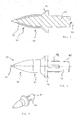
- the dental hand tool 10 shown has a handle 12 which partially carries a corrugation 14 in a manner known per se. This serves for better graspability and accordingly handling.
- the dental hand tool 10 is formed on both sides, so that two connection parts 16 and 18 extend away from the end of the handle 12.
- a coupling member 20 or 22 is connected to each of these.
- This has a ring 24 or 25, respectively.
- connection parts 16 and 18 have an essentially slightly conical structure when viewed over their course.
- the bends on each connection part are directed in opposite directions to one another - in any case in a known manner.
- the first elbow 26a extends in the illustrated embodiment in the drawing at an angle of approximately 25 degrees upwards.
- the second bend 26b is angled again in the opposite direction by 75 degrees, ie downwards.
- a third elbow 26c is provided, which in turn extends at an angle of approximately 73.5 degrees to the connecting part adjoining it, and again upwards.
- the resulting angle of attack is thus 113.5 degrees, based on the angle between the longitudinal axis of the handle 12 and the longitudinal axis 32 of the modeling tip.
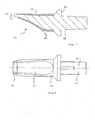
- the ring 24 or 25 according to the invention is intended to accommodate one modeling tip 30 each, with its shaft, as is shown in FIG Fig. 3 is explained in more detail.
- the ring 24 is in Fig. 2 shown enlarged. It has an axis 32, which coincides with the axis of the modeling tip and, in any case, runs significantly obliquely with respect to the connecting part 16.
- the average recess 34 of the ring is provided with radii at each end.
- the ring 26 has a spherical outer shape 36 which tapers slightly conically towards the front end 38.
- a modeling tip 30 according to the invention can be seen in an exemplary embodiment.
- a shaft 40 is intended to% in the passage recess 34 of the ring 24 to be included.
- 4 parallel clamping webs 42 are provided. These are intended for the system on the inside of the ring 24 and improve the pull-out security.
- a flange 44 is provided next to the shaft 40, the outer diameter of which essentially corresponds to the outer diameter of the ring 24 at the front end 38.
- the flange 44 tapers towards the front. This is followed by a cylindrical region 50, which is comparatively short, for example between half and the simple of a shaft diameter.
- a pin arrangement consisting of one or more pins is suitable for this purpose, which counteracts a translatory movement of the modeling tip 30.
- a cone can be formed with a corresponding counter-cone, which is also suitable for the formation of a stop.
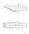
- a front area 52 of the modeling tip 30 is provided.
- both the front area 52 and the cylindrical area 50 are covered by a coating 54, for which purpose Fig. 4 is to be referred.
- the coating 54 consists of a material with greater flexibility and extremely low coefficient of static friction.
- elastomers but also coatings made of other suitable plastics such as polyethylene or polytetraflurethylene can be used.
- the material of the modeling tip 30 is otherwise harder. In this respect, it forms a core 56 in relation to the coating.
- the core 56 ends in a core tip 60 which the coating 54 - and thus the front region 52 - passes through.
- the core tip 60 is conical and ends in a small radius, which can be, for example, between 0.01 and 0.1 mm.
- the core tip (60) also serves to create demanding anatomical structures.
- Modeling tips 30 with different core tips can be used; for example, the further core tip could have an end radius of 1 mm, for example, and accordingly have a smoothing function.
- the layer thickness of the coating 54 decreases towards the front.
- the decrease in layer thickness is accompanied by a reduction in the diameter of the modeling tip.
- the coating is also less strong, so that the reduction in the flexibility of the coating is compensated for by the reduction in the dimensional stability.
- Fig. 5 it can be seen in what way a modeling tip can be seen in perspective.
- the rear end 62 of the shaft 40 is blunt, and the modeling tip 30 can be easily pushed out of the ring 24 via this.
- a modeling tip according to the invention can also be designed.
- the basic shape of this modeling tip 30 is chisel-like or spatula-like and not circular-symmetrical.
- the core tip 60 in turn protrudes from the coating 54.
- the core tip 60 here forms a flat blade 66 which is particularly well suited for modeling in certain applications.
- FIG. 8 shows a sectional view through a further exemplary embodiment of a modeling tip 30 according to the invention.
- This embodiment has a shaft 40 which is provided with clamping webs 42.
- a flange 44 which in turn has a circular circumferential extension, extends to this towards the front.
- a cylindrical region 50 is provided, to which a front region 52 of the modeling tip 30 adjoins at the front.
- the front area 52 has essentially a chisel shape and is therefore not circular. It tapers to the front, with a core tip 60 extending further forward than a coating 54.
- the modeling tip 30 consists of a core 56 which is made of a material which is softer or harder than the material of the coating 54.
- the shape of the chisel-shaped modeling tip 30 according to Fig. 8 can also be easily compared with the 8 and 9 see.
- the coating 54 consists (in this embodiment) either of an elastomer or z. B. from ceramic or metal, while a suitable plastic material such as polyamide or polypropylene, or polyethylene, is used as the material for the core 56.
- the coating 54 is - as from Fig. 9 can be seen - provided over one side of the front area 52, specifically over the one with the groove 70. This side is then preferably used by the dentist for non-adhesive adaptation, the groove 70 being particularly well suited for the formation of spherical configurations.
- the fine modeling can, for example, represent fissures, in turn, can be implemented with the core tip 60.
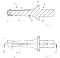
- a further embodiment of a dental hand tool with a modeling tip 30 is provided for the sake of explanation 10 and 11 evident.
- an essentially conical region 72 is subsequently provided on the flange 44.
- the conical area 72 has a coating 54.
- the coating 54 extends in a circular manner in a coating ring 73, but then only in the form of a partial circle in the direction of the coating ring (73).
- the pitch circle angle is approximately 20 degrees
- a web 75 made of the core material 56 extends over the rest to 360 degrees, that is to say over 340 degrees.
- a stuffing ball 74 is provided at the front, tapered end of the conical area 72. This is completely surrounded by the elastomer material of the coating 54.
- Matrix tapes are used for the realization of rather large-volume dental restorations in a manner known per se. They are often made of steel such as stainless steel.
- the web 75 which is free of elastomer material, slide along the matrix band when the contact point is to be created on the approximal surface. This reliably prevents elastomer parts from coming off due to contact with the sharp steel edge of the matrix tape.
- the hollow back can then be used to guide the matrix belt when filling class 2 cavities.
Description
Die Erfindung betrifft ein Dental-Handwerkzeug, gemäß dem Oberbegriff von Anspruch 1.The invention relates to a dental hand tool, according to the preamble of claim 1.
Dental-Handwerkzeuge, die auch als dentale Handinstrumente bezeichnet werden, sind seit langem bekannt. Derartige Handwerkzeuge sind entweder einstückig oder weisen auswechselbare Spitzen, beispielsweise Modellierspitzen auf. Die Spitzen sind typischerweise abgekröpft, beispielsweise nach der Art von Schwanenhälsen, um dem Zahnarzt die Bearbeitung auch an Stellen zu ermöglichen, die von der Mundöffnung des Patienten abgewandt sind, also an distalen Bereichen von Zähnen beziehungsweise in Zahnzwischenräumen von Molaren.Dental hand tools, which are also referred to as dental hand instruments, have been known for a long time. Such hand tools are either in one piece or have interchangeable tips, for example modeling tips. The tips are typically bent, for example in the manner of goosenecks, in order to enable the dentist to work on areas that are facing away from the mouth opening of the patient, that is to say on distal areas of teeth or in interdental spaces of molars.
Es ist seit langem bekannt, dass man durch unterschiedlich abgekröpfte Spitzen die Handhabbarkeit verbessern kann, wobei es auch bekannt ist, Spitzen zu verschiedenen Zwecken zu realisieren, also beispielsweise Löffelspitzen, Spatenspitzen, Spitzen zum Feilen und dergleichen, zur Verfügung zu stellen, um den unterschiedlichen erforderlichen Bearbeitungsvorgängen durch den Zahnarzt Rechnung zu tragen.
Ein Beispiel für eine derartige Lösung aus noch relativ neuerer Zeit ist aus der
Diese Lösung erlaubt zwar die Ausübung von bedeutenden Kräften durch den Zahnarzt, und auch eine sichere Halterung der Spitze an dem Dental-Handwerkzeug im übrigen. Das dortige Kupplungsglied stellt andererseits ein Sackloch zur Verfügung, das tiefliegend und schlecht zu reinigen ist, so dass sich dort ohne regelmäßiges Autoklavieren bakterielle Verschmutzungen ansammeln.Although this solution allows significant forces to be exerted by the dentist, the rest of the tip is also securely held on the dental hand tool. The coupling member there, on the other hand, provides a blind hole that is deep and difficult to clean, so that there is no regular autoclaving accumulate bacterial contamination.
Typischerweise werden Dental-Handwerkzeuge für unter anderem auch zum Stopfen und zum Modellieren von Füllungsmaterialien verwendet. Für das Stopfen ist es günstig, eine ballige relativ voluminöse Spitze zu verwenden, beispielsweise gemäß der
Um diesen beiden unterschiedlichen Forderungen Rechnung zu tragen, werden typischerweise in der Zahnarztpraxis mindestens zwei verschiedene Arten von Dental-Handwerkzeugen bereitgehalten, und zu dem je in unterschiedlichen Ausgestaltungen. Demgegenüber liegt der Erfindung die Aufgabe zugrunde, ein Dental-Handwerkzeug gemäß dem Oberbegriff von Anspruch 1 zu schaffen, das universeller verwendbar ist, insbesondere sowohl für das Modellieren als auch für modelliernahe Tätigkeiten des Zahnarztes, leichter handzuhaben ist, aber dennoch keinen hygienischen Bedenken begegnet.In order to take these two different requirements into account, at least two different types of dental hand tools are typically kept available in the dental practice, and each in different configurations. In contrast, the invention has for its object to provide a dental hand tool according to the preamble of claim 1, which can be used more universally, in particular both for modeling and for modeling-related activities of the dentist, is easier to handle, but still meets no hygienic concerns.
Diese Aufgabe wird erfindungsgemäß durch Anspruch 1 gelöst. Vorteilhafte Weiterbildungen ergeben sich aus der Unteransprüchen.This object is achieved by claim 1. Advantageous further developments result from the subclaims.
Erfindungsgemäß ist es vorgesehen, dass ein Dental-Handwerkzeug eine Modellierspitze aufweist, die überwiegend aus einem harten Material wie einem harten Kunststoff besteht. Der vordere Bereich der Modellierspitze ist mit einer Beschichtung versehen, die gegenüber dem Kern der Modellierspitze weicher ist. Im Bereich der Beschichtung ist die Ausgestaltung ballig, und bevorzugt ragt der Kern mit seinem vorderen Ende aus der Modellierspitze heraus.According to the invention, it is provided that a dental hand tool has a modeling tip which mainly consists of a hard material such as a hard plastic. The front area of the modeling tip is provided with a coating that is softer than the core of the modeling tip. In the area of the coating, the configuration is spherical, and the front end of the core preferably protrudes from the modeling tip.
Hierdurch lässt sich über seitliche Druckausübung im Bereich der Beschichtung eine Stopfwirkung erzielen. Das kurze herausragende Ende des Kerns erlaubt ein feines modellieren und ziselieren. Besonders bevorzugt ist die Beschichtung als Elastomer ausgebildet, das eine geringe Oberflächenenergie,eine geringe Benetzneigung sowie sehr gute Antihaft-Eigenschaften aufweist.In this way, a tamping effect can be achieved by exerting lateral pressure in the area of the coating. The short protruding end of the core allows fine modeling and chasing. The coating is particularly preferably designed as an elastomer, which has a low surface energy, a low tendency to wet and very good non-stick properties.
Bevorzugt ist die Modellierspitze als Zwei-Komponenten-Teil aufgebaut, der einen steifen Kern aus einem harten Trägerkunststoff mit einer im wesentlichen gleichmäßig dünnen Schicht aus einem dehäsiven Elastomer kombiniert.
Das Material der Beschichtung ist so ausgewählt, dass es eine besonders geringe Oberflächenenergie aufweist. Diese beträgt bevorzugt weniger als 35 mN/m. Das Material ist bevorzugt so ausgewählt, dass die Benetzungsneigung ausgesprochen gering ist. Zu den geeigneten Materialien gehören insofern Elastomere, Silikone, PTFE, aber auch beispielsweise ein Polyolefin. Wenn als Material für die Beschichtung ein geschäumtes Material verwendet wird, ist es bevorzugt, einen geschlossenporigen Schaum zu verwenden. Die Oberflächenschicht des Schaums kann auch nachverdichtet sein, so dass sie blasenfrei ist.The modeling tip is preferably constructed as a two-component part, which has a rigid core made of a hard carrier plastic with an essentially uniformly thin one Combined layer of a adhesive elastomer.
The material of the coating is selected so that it has a particularly low surface energy. This is preferably less than 35 mN / m. The material is preferably selected so that the tendency to wet is extremely low. Suitable materials include elastomers, silicones, PTFE, but also, for example, a polyolefin. If a foamed material is used as the material for the coating, it is preferred to use a closed-pore foam. The surface layer of the foam can also be densified so that it is free of bubbles.
Eine Ausgestaltung mit einer besonders nachgiebigen Beschichtung, gepaart mit einer feinen Kernspitze, ist überraschend besonders günstig, wenn es gilt, sowohl Modellieraufgaben als auch Füllungaufgaben mit der gleichen Modellierspitze zu bewältigen.A configuration with a particularly flexible coating, paired with a fine core tip, is surprisingly particularly favorable when it is a matter of mastering both modeling tasks and filling tasks with the same modeling tip.
Die Schichtstärke der Beschichtung kann beispielsweise 0,15 bis 0,25mm betragen. Sie ist gleichmäßig, nimmt jedoch an dem vorderen Ende ab.The layer thickness of the coating can be, for example, 0.15 to 0.25 mm. It is even, but decreases at the front end.
Der Kern ragt um etwa 0,25 bis 0,75, bevorzugt um 0,5mm aus der Beschichtung vorne heraus. Dies ermöglicht ein präzises Modellieren gerade auch von Dentalmaterialien aus Komposit.The core protrudes from the coating at the front by approximately 0.25 to 0.75, preferably by 0.5 mm. This enables precise modeling, particularly of composite dental materials.
Überraschend erlaubt diese Ausgestaltung es, das Anhaften der Modellierspitze am Komposit zu verhindern, obwohl ein - wenn auch geringer - Kontakt zwischen dem Kern der Spitze und dem Komposit vorliegt.Surprisingly, this configuration makes it possible to prevent the modeling tip from sticking to the composite, even though there is - albeit slight - contact between the core of the tip and the composite.
Die geringe Schichtstärke der Beschichtung erlaubt zudem die gute Wiedergabe der entstehenden Scherkräfte, so dass sich auch sehr filigrane anatomische Zahnstrukturen gestalten lassen.The low layer thickness of the coating also allows the resulting shear forces to be reproduced well, so that even very delicate anatomical tooth structures can be designed.
Die erfindungsgemäße Beschichtung ist nicht auf die Verwendung von Elastomeren beschränkt. Anstelle dessen lässt sich beispielsweise auch eine Beschichtung aus Polytetraflurethylen einsetzen, oder eine Beschichtung aus einem beliebigen anderen Material, das deutlich weicher als das Material des Kerns ist.The coating according to the invention is not limited to the use of elastomers. Instead of this, for example, a coating made of polytetraflurethylene can also be used, or a coating made of any other material that is significantly softer than the material of the core.
So ist es beispielsweise auch möglich, die Beschichtung im wesentlichen aus einem geschlossenporigen Schaum zu erstellen, dessen Außenfläche insbesondere geglättet ist, beispielsweise durch Wärmeeinwirkung.For example, it is also possible to create the coating essentially from a closed-cell foam, the outer surface of which is particularly smoothed, for example by the action of heat.
Besonders günstig ist es, wenn ein Anschlussteil des Dental-Handwerkzeugs für die Verbindung mit einem besonderen Kupplungsglied bereitgestellt wird. Das Anschlussteil kann dann zwei zueinander entgegengesetzte Abkröpfungen umfassen. Das Kupplungsglied erstreckt sich bevorzugt so, dass sich ein Winkel von etwa 90 Grad zum letzten Abschnitt des Anschlussteils zum Kupplungsglied hin erstreckt. Hierzu weist das Kupplungsglied einen Ring auf, der den Schaft der Modellierspitze aufnimmt und von diesem durchtreten wird.It is particularly favorable if a connecting part of the dental hand tool for the Connection is provided with a special coupling member. The connecting part can then comprise two bends that are opposite one another. The coupling member preferably extends such that an angle of approximately 90 degrees to the last section of the connecting part extends to the coupling member. For this purpose, the coupling member has a ring which receives the shaft of the modeling tip and will pass through it.
Bevorzugt sind eine Erstabkröpfung, eine Zweitabkröpfung und eine Drittabkröpfung vorgesehen. Deren Kröpfungswinkel sind zueinander entgegengesetzt. Bevorzugt ist der Drittabkröpfungswinkel vergleichsweise groß, z.B. über 60 Grad. Der letzte kurze Abschnitt des Anschlussteils jenseits der Drittabkröpfung kann sich quer zum Ring des Kupplungsglieds erstrecken - oder in Verlängerung deren Fläche -, so dass auch ein starke Gesamtabkröpfung möglich ist, wie sie besonders bei Arbeiten an distalen Bereichen von Molaren günstig ist.A first bend, a second bend and a third bend are preferably provided. Their offset angles are opposite to each other. The third offset angle is preferably comparatively large, e.g. over 60 degrees. The last short section of the connecting part beyond the third bend can extend transversely to the ring of the coupling member - or in extension of its surface - so that a strong overall bend is also possible, which is particularly advantageous when working on distal areas of molars.
Dies erlaubt es nicht nur, die Modellierspitze sicher zu entnehmen, und zwar durch Druck auf den rückwärtigen Bereich des Schafts, sondern auch eine verschmutzungsarme und leicht zu reinigende Realisierung des Kupplungsglieds. Ein derartiges Kupplungsglied lässt sich wesentlich leichter reinigen und sterilisieren als ein Sackloch.This not only makes it possible to safely remove the modeling tip by applying pressure to the rear area of the shaft, but also to realize the coupling member with little dirt and easy to clean. Such a coupling member is much easier to clean and sterilize than a blind hole.
Darüberhinaus ist diese Ausgestaltung praktisch eine Voraussetzung für die Realisierung der Modellierspitze mit einer Antihaft-Beschichtung. Eine Modellierspitze mit einer Antihaft-Beschichtung lässt mit nahezu nicht ausziehen, hingegen wohl aus dem Kupplungsglied herausdrücken. Durch die Nachgiebigkeit der Beschichtung, gepaart mit deren glatter Oberfläche, entsteht eine deutlich Reduktion des Haftreibungskoeffizienten, was zu der erwünschten Wirkung führt, dass das bearbeitete Komposit dort nicht anhaftet.In addition, this configuration is practically a prerequisite for the realization of the modeling tip with a non-stick coating. A modeling tip with a non-stick coating can hardly be pulled out, but it can be pushed out of the coupling link. The flexibility of the coating, coupled with its smooth surface, results in a significant reduction in the coefficient of static friction, which leads to the desired effect that the processed composite does not adhere there.
Alternativ kann der Anschlag auch in beliebigen anderen Weise ausgebildet sein. Eine punktuelle Anlage an z.B. zwei oder 3 einander gegenüberliegenden Punkten ist ebenso möglich wie eine konische Aufnahme mit Klemmpressung, oder auch eine Rastverbindung. Die Rastverbindung kann z.B. durch flache Retentionsvorsprünge realisiert werden, die auf dem Schaft ausgebildet sind, jenseits des vorderen Bereichs, und von hinten an dem Ring des Kupplungsglieds anliegen. Beim Eindrücken der Modellierspitze in den Ring verformen sich diese Rastvorsprünge leicht. Durch die federbelastete Anlage an der Rückfläche des Ringes entsteht eine Vorspannung, die die Modellierspitze sicher im Ring fixiert.Alternatively, the stop can also be designed in any other way. A selective plant on e.g. two or 3 points opposite each other is possible as well as a conical receptacle with clamping pressure or a snap connection. The latching connection can e.g. can be realized by flat retention projections, which are formed on the shaft, beyond the front region, and bear against the ring of the coupling member from the rear. When the modeling tip is pressed into the ring, these locking projections deform slightly. The spring-loaded contact on the rear surface of the ring creates a preload that securely fixes the modeling tip in the ring.
Dennoch ist sie durch Druck von hinten auf den Schaft leicht entnehmbar. Bevorzugt ist die Kraft, die für das Lösen der Verbindung zwischen dem Kupplungsglied und der Modellierspitze erforderlich ist, erheblich, z.B. mind. 50 N.Nevertheless, it can be easily removed by applying pressure to the shaft from behind. The force which is required for releasing the connection between the coupling member and the modeling tip is preferably considerable, for example at least 50 N.
Der Schaft der Modellierspitze ist bevorzugt mit Klemmstegen versehen, die in einer geeigneten Anzahl gleichmäßig um den Umfang des Schafts verteilt sind, Alternativ können auch Noppen vorgesehen sein, die zB. auch in entsprechende Vertiefungen im Ring gehalten sein können.The shaft of the modeling tip is preferably provided with clamping webs, which are distributed in a suitable number evenly around the circumference of the shaft. Alternatively, knobs can also be provided, for example. can also be held in corresponding recesses in the ring.
Insofern ergibt sich mit der Erfindung der überraschende Vorteil, dass trotz der Möglichkeit, auch anspruchsvolle anatomische Strukturen erstellen zu können, die Haftung auch gegenüber Komposits ausgesprochen gering ist. Überraschend wird diese auch nicht durch die herausragende Kernspitze erhöht.In this respect, the invention has the surprising advantage that, despite the possibility of also being able to create sophisticated anatomical structures, the adhesion to composites is extremely low. Surprisingly, this is not increased by the outstanding core tip.
Ein erfindungsgemäß besonderer Vorteil liegt darin begründet, dass die erfindungsgemäße Modellierspitze das Kupplungsglied durchtritt: Der herausragende Schaft erlaubt im Gegensatz zum Stand der Technik das Ausüben von Druck auf diesen, so dass eine leichte Entnahme möglich ist. Dies erlaubt es erst mit Komponenten mit einem sehr geringen Gleitreibungskoeffizienten zu arbeiten. Die bisher verwendeten Kupplungsglieder mit Sackloch verlangen das Herausziehen von Modellierspitzen, was jedoch durch eine Oberfläche mit geringem Reibungskoeffizienten deutlich erschwert wird. Die erfindungsgemäße Lösung ist demgegenüber hiervon unabhängig.A particular advantage according to the invention lies in the fact that the modeling tip according to the invention passes through the coupling member: in contrast to the prior art, the outstanding shaft allows pressure to be exerted on it, so that easy removal is possible. This makes it possible to work with components with a very low sliding friction coefficient. The coupling elements with a blind hole used up to now require the removal of modeling tips, but this is made significantly more difficult by a surface with a low coefficient of friction. In contrast, the solution according to the invention is independent of this.
Dies erlaubt es andererseits, die Festigkeit der Lagerung der Modellierspitze im Kupplungsglied noch zu erhöhen, was der Neigung der Modellierspitzen, bei der Betätigung und bei den aufgewendeten Scherkräften verloren zu gehen, entgegenwirkt.On the other hand, this allows the strength of the mounting of the modeling tip in the coupling member to be increased, which counteracts the tendency of the modeling tips to be lost during actuation and in the shear forces applied.
Besonders bevorzugt ist es, dass die Modellierspitze einen Kern aufweist, der die Beschichtung durchtritt und an seinem vorderen Ende frei von der Beschichtung ist. Es ist aber auch möglich, die Beschichtung lediglich teilumlaufend hervorzusehen, so dass ein Steg verbleibt, der frei von einer Beschichtung ist und sich vom vorderen Ende der Modellierspitze rückwärts bis zum Flansch erstreckt.It is particularly preferred that the modeling tip has a core that passes through the coating and is free of the coating at its front end. However, it is also possible to provide the coating only partially around it, so that a web remains which is free of a coating and extends backwards from the front end of the modeling tip to the flange.
Eine derartige Lösung ist besonders für die Realisierung mit der Spritzgusstechnik geeignet; der Anspritzpunkt kann dann weiter in den rückwärtigen Bereich hinein verlagert werden, so dass das vordere Ende der Modellierspitze frei von Anspritzpunkten ist.Such a solution is particularly suitable for implementation using injection molding technology; the injection point can then be shifted further into the rear area, so that the front end of the modeling tip is free of injection points.
Es versteht sich, dass anstelle der Spritzgusstechnik auch beliebige andere geeignete Herstellmöglichkeiten verwendet werden können. So lässt sich die Modellierspitze auch in einem Pressprozess herstellen, und es ist auch möglich, die Beschichtung bzw. gegebenenfalls weitere Schichten nach Belieben des Fachmanns in einem Tauchprozess oder auch in einem Lackierprozess zu realisieren.It goes without saying that any other suitable manufacturing options can also be used instead of the injection molding technique. In this way, the modeling tip can also be produced in a pressing process, and it is also possible to implement the coating or, if appropriate, further layers in a dipping process or also in a painting process, at the discretion of the person skilled in the art.
Weitere Einzelheiten, Vorteile und Merkmale ergeben sich aus der nachfolgenden Beschreibung mehrerer Ausführungsbeispiele anhand der Zeichnung.
Es zeigen:
- Fig. 1
- eine schematische Ansicht eines erfindungsgemäßen Dental-Handwerkszeugs, in perspektivischer Darstellung;
- Fig. 2
- das Kupplungsglied als Detail aus
Fig. 1 ; - Fig. 3
- eine Seitenansicht einer erfindungsgemäßen Modellierspitze in einer Ausführungsform;
- Fig. 4
- die Modellierspitze gemäß
Fig. 3 , jedoch in Schnittdarstellung; - Fig. 5
- eine perspektivische Ansicht einer erfindungsgemäßen Modellierspitze;
- Fig. 6
- eine Seitenansicht einer weiteren Ausführungsform einer erfindungsgemäßen Modellierspitze; und
- Fig. 7
- die Schnittansicht durch die Modellierspitze gemäß
Fig. 6 ; - Fig. 8
- eine schematische Schnittansicht einer weiteren Ausführungsform einer erfindungsgemäßen Modellierspitze;
- Fig. 9
- eine Draufsicht auf die Modellierspitze in der Ausführungsform gemäß
Fig. 8 ; - Fig. 10
- eine erläuterungshalber beigefügte Schnittansicht einer Modellierspitze, die keine Ausführungsform der Erfindung zeigt; und
- Fig. 11
- eine erläuterungshalber beigefügte Draufsicht auf die Modellierspitze gemäß
Fig. 10 , wobei der Schnitt gemäßFig. 10 entlang A-A erfolgt ist.
Show it:
- Fig. 1
- a schematic view of a dental hand tool according to the invention, in a perspective view;
- Fig. 2
- the coupling link as a detail
Fig. 1 ; - Fig. 3
- a side view of a modeling tip according to the invention in one embodiment;
- Fig. 4
- the modeling tip according to
Fig. 3 , but in a sectional view; - Fig. 5
- a perspective view of a modeling tip according to the invention;
- Fig. 6
- a side view of another embodiment of a modeling tip according to the invention; and
- Fig. 7
- the sectional view through the modeling tip according
Fig. 6 ; - Fig. 8
- is a schematic sectional view of a further embodiment of a modeling tip according to the invention;
- Fig. 9
- a plan view of the modeling tip in the embodiment according to
Fig. 8 ; - Fig. 10
- an explanatory sectional view of a modeling tip, which shows no embodiment of the invention; and
- Fig. 11
- an explanatory plan view of the modeling tip according to
Fig. 10 , the cut according toFig. 10 along AA.
Das in
Das Dental-Handwerkzeug 10 ist in dem dargestellten Ausführungsbeispiel beidseitig ausgebildet, so dass sich von dem Griff 12 zwei Anschlussteile 16 und 18 endseitig wegerstrecken. An diesen angeschlossen ist je ein Kupplungsglied 20 beziehungsweise 22. Dieses weist je einen Ring 24 beziehungsweise 25 auf. Insofern liegt eine im Grunde mittensymetrische Ausgestaltung vor, wobei die Anschlussteile 16 und 18 je Abkröpfungen 26 und 28 aufweisen, die voneinander etwas verschieden sind.In the exemplary embodiment shown, the
Derartige unterschiedliche Apkröpfungen sind an sich bekannt, und dienen dazu, die Ergonomie bei Betätigung an schlecht zugänglichen Stellen im Mundraum des Patienten zu verbessern.Such different Apkröpfungen are known per se, and serve to improve the ergonomics when actuated in difficult to access places in the patient's mouth.
Die Anschlussteile 16 und 18 weisen über ihren Verlauf betrachtet einen im wesentlichen leicht konischen Aufbau auf. Die Abkröpfungen an jedem Anschlussteil sind zueinander - in jedenfalls bekannter Weise - entgegengesetzt gerichtet.The
Die Erstabkröpfung 26a verläuft in dem dargestellten Ausführungsbeispiel in der Zeichnung in einem Winkel von etwa 25 Grad nach oben. Die Zweitabkröpfung 26b verläuft in die entgegengesetzte Richtung erneut um 75 Grad abgewinkelt, also nach unten. Unmittelbar angrenzend an das Kupplungsglied 20 ist eine Drittabkröpfüng 26c vorgesehen, die wiederum in einem Winkel von etwa 73,5 Grad zum sich hieran anschließenden Anschlussteil verläuft, und wiederum nach oben. Der resultierende Anstellwinkel beträgt damit 113,5 Grad, bezogen auf den Winkel zwischen der Längsachse des Griffs 12 und der Modellierspitzen-Längsachse 32.The
Es versteht sich, dass die genannten Winkel lediglich beispielhaft zu verstehen sind. Für die Erfindung wesentlich ist jedoch die recht starke Abkröpfung des Rings 24 beziehungsweise 25 gegenüber dem Anschlussteil - hier beispielsweise im Winkel von 70 Grad -.It is understood that the angles mentioned are only to be understood as examples. However, what is essential for the invention is the fairly strong cranking of the
Der erfindungsgemäße Ring 24 beziehungsweise 25 ist dafür bestimmt, je eine Modellierspitze 30 aufzunemen, und zwar mit ihrem Schaft, wie es anhand von
Der Ring 24 ist in
Der Ring 26 weist eine ballige Außenform 36 auf, die zum vorderen Ende 38 hin leicht konisch schräg zuläuft.The
Aus
Anschließend an den Schaft 40 ist ein Flansch 44 vorgesehen, dessen Außendurchmesser im wesentlichen dem Außendurchmesser des Rings 24 an dem vorderen Ende 38 entspricht. Der Flansch 44 verjüngt sich nach vorne hin. Hieran anschließend ist ein zylindrischer Bereich 50 ausgebildet, der vergleichsweise kurz ist, beispielsweise zwischen der Hälfte und dem Einfachen eines Schaftdurchmessers beträgt.A
Anstelle eines kreisförmigen Flansches ist es auch möglich, eine beliebige andere Geometrik auszubilden, die als Anschlag geeignet ist. Beispielsweise ist eine Stiftanordnung aus einem oder mehreren Stiften hierfür geeignet, die einer translatorischen Bewegung der Modellierspitze 30 entgegenwirkt. Alternativ kann auch ein Konus mit einem entsprechendem Gegenkonus ausgebildet sein, der ebenfalls für die Ausbildung eines Anschlags geeignet ist.Instead of a circular flange, it is also possible to design any other geometry that is suitable as a stop. For example, a pin arrangement consisting of one or more pins is suitable for this purpose, which counteracts a translatory movement of the
Anschließend an den zylindrischen Bereich 50 ist ein vorderer Bereich 52 der Modellierspitze 30 vorgesehen.Following the
Sowohl der vordere Bereich 52 als auch der zylindrische Bereich 50 sind erfindungsgemäß von einer Beschichtung 54 abgedeckt, wozu auf
Demgegenüber ist das Material der Modellierspitze 30 im übrigen härter. Es bildet gegenüber der Beschichtung insofern einen Kern 56.In contrast, the material of the
Der Kern 56 endet in einer Kernspitze 60, die die Beschichtung 54 - und damit den vorderen Bereich 52 - durchtritt. Die Kernspitze 60 ist konisch ausgebildet und endet in einem kleinen Radius, der beispielsweise zwischen 0,01 und 0,1mm betragen kann.The core 56 ends in a
Während der vordere Bereich 52 - und teilweise auch der zylindrische Bereich 54 bei der Handhabung besonders geeignet sind, das aufgebrachte Material anzudrücken und ihm gegebenenfalls eine geglättete Oberfläche zu geben, dient die Kernspitze (60) zur Schaffung auch anspruchsvoller anatomischer Strukturen.While the front area 52 - and in some cases also the cylindrical area 54 - are particularly suitable for handling, pressing on the material applied and, if necessary, giving it a smoothed surface, the core tip (60) also serves to create demanding anatomical structures.
Es versteht sich, dass beidseitig des erfindungsgemäßen Dental-Handwerkzeugs 10 auch Modellierspitzen 30 mit unterschiedlichen Kernspitzen eingesetzt werden können; so könnte beispielsweise die weitere Kernspitze einen Endradius von beispielsweise 1mm haben, und dementsprechend eine Glättungsfunktion aufweisen.It goes without saying that the
Aus
Aus
Aus
Hier wie auch in den weiteren Figuren weisen gleiche Bezugszeichen auf gleiche Teile hin und bedürfen keiner zusätzlichen Erläuterung.Here, as in the other figures, the same reference symbols refer to the same parts and do not require any additional explanation.
Er versteht sich, dass sich auch bei der Ausführungsform gemäß den
Die Modellierspitze 30 besteht - abgesehen von der Beschichtung 54 - aus einem Kern 56, der aus einem Material besteht, das weicher oder härter ist als das Material der Beschichtung 54 ist.Except for the
Die Form der meißelförmigen Modellierspitze 30 gemäß
Die Beschichtung 54 ist - wie aus
Die Feinmodellation kann zur Darstellung zum Beispiel von Fissuren lässt sich wiederum mit der Kernspitze 60 realisieren.The fine modeling can, for example, represent fissures, in turn, can be implemented with the
Eine weitere erläuterungshalber beigefügte Ausgestaltung eines Dental-Handwerkzeugs mit einer Modellierspitze 30 ist aus
Anschließend an das vordere, verjüngte Ende des konischen Bereichs 72 ist eine Stopfkugel 74 vorgesehen. Diese ist vollständig von dem Elastomer-Material der Beschichtung 54 umgeben.A stuffing
Diese Ausgestaltung einer Modellierspitze 30 ist besonders für die Verbindung mit einem Matritzenband günstig. Matritzenbänder werden für die Realisierung eher großvolumiger Dentalrestaurationen in an sich bekannterweise verwendet. Sie bestehen häufig aus Stahl wie Edelstahl.This configuration of a
Es ist nun vorgesehen, den Steg 75, der frei von Elastomer-Material ist, an dem Matritzenband entlang gleiten zu lassen, wenn der Kontaktpunkt an der Approximalfläche erstellt werden soll. Hierdurch ist sicher verhindert, dass sich Elastomerteile aufgrund des Kontaktes mit der scharfen Stahlkante des Matritzenbandes ablösen können.It is now provided that the
Um dies auch bei der Ausfürungsform gemäß den
Claims (15)
- A handheld dental tool, comprising a handle (12) with at least one connecting part (16) and a coupling member (20) at one end, and a second connecting part (18) and a second coupling member (22) at the other end of the handle (12), wherein a modelling tip (30) having a shank is provided to fit the coupling member, and that the modelling tip (30) has a coating (54) of a material which otherwise is more flexible with respect to the material of the modelling tip (30),
wherein the material of the coating has a surface energy of less than 35mN/m with respect to the material of the modelling tip,
characterized in that the modelling tip (30) comprises a core which terminates in a core tip and which passes through the coating and hence a front region (52) of the modelling tip (30) and, at the front end thereof, is free of the coating (54),
and wherein the layer thickness of the coating (54) decreases towards the front. - The handheld dental tool according to claim 1, characterized in that the connecting part (16, 18), as viewed from the handle towards the coupling member (20; 22), is each conically tapered or tapered at least across part of the length and across more than half of the length.
- The handheld dental tool according to one of the preceding claims, characterized in that the coupling member is formed as a ring (24) which, with its normal, extends to the axis (32) of the connecting part (16).
- The handheld dental tool according to claim 3, characterized in that rings, as coupling members (20, 22), have mutually different crank angles and/or different geometries of the connecting parts and/or mutually identical crank angles and different modelling tips (30), at the two ends of the handheld dental tool.
- The handheld dental tool according to one of the preceding claims, characterized in that the connecting part (16; 18) has at least two cranks which, as viewed one after another, are directed at an angle towards each another, the crank adjacent to the coupling angle being aligned such that the angle between the surface spanned by the coupling member (20, 22) and the adjacent connecting part (16; 18) is less than 90 degrees.
- The handheld dental tool according to one of the preceding claims, characterized in that the modelling tip (30) passes through a ring (24) of the coupling member (20; 22) with its shank (40) and can be removed from the coupling member (20; 22) by pressing on the rear end of the shank (40).
- The handheld dental tool according to one of the preceding claims, characterized in that a shank of the modelling tip (30) has retention projections or clamping webs (42) which are intended to bear against a ring (24) of the coupling member (20; 22).
- The handheld dental tool according to claim 7, characterized in that the clamping webs (42) of the shank (40), when in press fit, bear against a ring (24) of the coupling member (20; 22) and the clamping webs (42) and/or the shank (40) deform in the coupled state, or in that the shank (40) is conical formed and the ring (24) comprising a matching counter-cone.
- The handheld dental tool according to one of the preceding claims, characterized in that the modelling tip (30) comprises one or more projections which are in the form of a flange (44), which flange (44) is of circular circumferential design and which projections are intended to bear against a ring (24; 26) of the coupling member (20; 22).
- The handheld dental tool according to one of the preceding claims, characterized in that the modelling tip (30) comprises one or more projections which are in the form of a flange (44) or projecting pins, which projections separate a front region from a shank (40) of the modelling tip (30) approximately centrally or such, that the front region of the modelling tip (30) projects further than the shank (40), and/or a flange (44) of the modelling tip (30) conically tapers towards the front end of the modelling tip (30) and/or a flange (44) of the modelling tip (30) is flush to the ring (24); 26) of the coupling member (20; 22).
- The handheld dental tool according to one of the preceding claims, characterized in that the coating (54) of the modelling tip (30) extends across a partial region of the length of the modelling tip (30) and/or the core (56) of the modelling tip (30) is covered across a large portion of the front region (50) of the coating (54).
- The handheld dental tool according to one of the preceding claims, characterized in that the coating (54) is applied to the modelling tip (30) in the manner of a sleeve, and a core (56) of the modelling tip (30) passes through the sleeve and/or the coating (54) is applied flush on the core (56) of the modelling tip (30) and has continuous transitions at its ends and/or the coating (54) is received in a receiving region of the core (56) of the modelling tip (30), which is recessed, when viewed in section of the modelling tip (30).
- The handheld dental tool according to one of the preceding claims, characterized in that a receiving region, for the coating on the modelling tip (30), conically tapers towards the front end of the modelling tip (30) and/or in that the coating (54) of the modelling tip (30) extends across a cylindrical region (50) of the modelling tip (30), which is adjacent to a flange (44) of the modelling tip (30), and/or in that the coating (54) extends across a conical region of the front region (50) of the modelling tip (30) and abuts a core (56) of the modelling tip.
- The handheld dental tool according to claim 13, characterized in that the coating (54) has a constant thickness across a major part of its length and conically tapers towards the front.
- The handheld dental tool according to one of the preceding claims, characterized in that a coating (54) at least in part annularly extends at an angle of wrap of more than 270 degrees around a front region (52) of a core (56) of the modelling tip (30) and the modelling tip (30) comprises a web (75) which extends flush to the coating (54) and additionally extends along the front region (52).
Priority Applications (4)
| Application Number | Priority Date | Filing Date | Title |
|---|---|---|---|
| EP15193647.3A EP3165193B1 (en) | 2015-11-09 | 2015-11-09 | Handheld dental tool |
| US15/047,913 US20170128157A1 (en) | 2015-11-09 | 2016-02-19 | Dental hand tool |
| PCT/EP2016/076812 WO2017080946A1 (en) | 2015-11-09 | 2016-11-07 | Handheld dental tool |
| CN201680065088.2A CN108289724B (en) | 2015-11-09 | 2016-11-07 | Dental hand tool |
Applications Claiming Priority (1)
| Application Number | Priority Date | Filing Date | Title |
|---|---|---|---|
| EP15193647.3A EP3165193B1 (en) | 2015-11-09 | 2015-11-09 | Handheld dental tool |
Publications (2)
| Publication Number | Publication Date |
|---|---|
| EP3165193A1 EP3165193A1 (en) | 2017-05-10 |
| EP3165193B1 true EP3165193B1 (en) | 2020-07-15 |
Family
ID=54477941
Family Applications (1)
| Application Number | Title | Priority Date | Filing Date |
|---|---|---|---|
| EP15193647.3A Active EP3165193B1 (en) | 2015-11-09 | 2015-11-09 | Handheld dental tool |
Country Status (4)
| Country | Link |
|---|---|
| US (1) | US20170128157A1 (en) |
| EP (1) | EP3165193B1 (en) |
| CN (1) | CN108289724B (en) |
| WO (1) | WO2017080946A1 (en) |
Families Citing this family (9)
| Publication number | Priority date | Publication date | Assignee | Title |
|---|---|---|---|---|
| USD844143S1 (en) * | 2016-01-26 | 2019-03-26 | Ivoclar Vivadent Ag | Modeling tip for dental use |
| USD895115S1 (en) | 2016-01-26 | 2020-09-01 | Ivoclar Vivadent Ag | Modeling tip for dental use |
| US10070942B1 (en) * | 2017-11-13 | 2018-09-11 | King Saud University | Orthodontic cinch back instrument |
| US10321973B1 (en) | 2017-11-27 | 2019-06-18 | King Abdulaziz University | Composite restoration condenser with rolling ball tip |
| US11432906B2 (en) * | 2018-06-18 | 2022-09-06 | Hu-Friedy Mfg. Co., Llc | Dental instrument with a flexible tip end and method of manufacture |
| US20200046457A1 (en) * | 2018-08-13 | 2020-02-13 | Evelyn Anne-Bauschka Ayers | Interim Provisional Restoration Placement Instrument-#1 |
| US20200046456A1 (en) * | 2018-08-13 | 2020-02-13 | Evelyn Anne-Bauschka Ayers | Interim therapeutic restoration and cavity liner placement (itr) instrument description |
| EP3858286B1 (en) * | 2020-01-28 | 2023-08-02 | Ferton Holding S.A. | Tool for a medical treatment |
| USD997356S1 (en) | 2021-11-04 | 2023-08-29 | Charles Buist, DMD, PA | Hand operated tool handle with an improved tool bit adapter |
Citations (1)
| Publication number | Priority date | Publication date | Assignee | Title |
|---|---|---|---|---|
| US20090130628A1 (en) * | 2007-05-29 | 2009-05-21 | Viscomi Brian D | Compressible composite shaping instrument |
Family Cites Families (16)
| Publication number | Priority date | Publication date | Assignee | Title |
|---|---|---|---|---|
| US1209789A (en) * | 1916-05-24 | 1916-12-26 | William E Wilson | Dental instrument. |
| US2147310A (en) * | 1935-05-16 | 1939-02-14 | Binney And Smith Co | Method of dry color painting |
| JPS49134896U (en) * | 1973-03-14 | 1974-11-20 | ||
| EP0147485A1 (en) * | 1983-12-30 | 1985-07-10 | Austenal International Inc. | Condensing instrument for packing and condensing in connection with placement of dental composite resin restorative materials |
| DE8418590U1 (en) * | 1984-06-20 | 1985-10-24 | Fath, Bruno, Dr.med., 8520 Erlangen | Teflon coating on dental filling instruments |
| US4552531A (en) | 1984-11-16 | 1985-11-12 | Howard Martin | Gauged root canal condenser spreader |
| DE29801831U1 (en) * | 1998-02-04 | 1998-03-19 | Mueller Peter Dr | Brush holder for use in dentistry |
| US6206698B1 (en) | 1999-12-01 | 2001-03-27 | Cheryl B. Billingsley | Pliable composite condensing instrument |
| FI20000302A (en) * | 2000-02-14 | 2001-08-15 | Lm Instr Oy | Handheld instrument and tip part of the instrument |
| US6705865B1 (en) * | 2002-02-26 | 2004-03-16 | Dennis W. Szymaitis | Dental hand instrument |
| DE10208957B4 (en) * | 2002-02-28 | 2004-02-19 | Aesculap Ag & Co. Kg | Dental instrument |
| US20030186195A1 (en) * | 2002-04-02 | 2003-10-02 | Comfort Biomedical, Inc. | Hand-held medical/dental tool |
| US20050130099A1 (en) * | 2003-12-15 | 2005-06-16 | Kerrhawe Sa | Instrument for distributing restorative material on a tooth surface |
| CA2699660C (en) * | 2007-09-17 | 2016-03-22 | Synergy Biosurgical Ag | Medical implant ii |
| US20120301848A1 (en) * | 2011-05-17 | 2012-11-29 | O'donnell Joseph P | Dental Composite Packing Instrument |
| EP2779934B1 (en) * | 2011-11-17 | 2016-08-03 | Loma Linda University | Device for placing root repair materials for root-end cavities |
-
2015
- 2015-11-09 EP EP15193647.3A patent/EP3165193B1/en active Active
-
2016
- 2016-02-19 US US15/047,913 patent/US20170128157A1/en not_active Abandoned
- 2016-11-07 WO PCT/EP2016/076812 patent/WO2017080946A1/en active Application Filing
- 2016-11-07 CN CN201680065088.2A patent/CN108289724B/en active Active
Patent Citations (1)
| Publication number | Priority date | Publication date | Assignee | Title |
|---|---|---|---|---|
| US20090130628A1 (en) * | 2007-05-29 | 2009-05-21 | Viscomi Brian D | Compressible composite shaping instrument |
Also Published As
| Publication number | Publication date |
|---|---|
| CN108289724A (en) | 2018-07-17 |
| EP3165193A1 (en) | 2017-05-10 |
| CN108289724B (en) | 2021-01-05 |
| US20170128157A1 (en) | 2017-05-11 |
| WO2017080946A1 (en) | 2017-05-18 |
Similar Documents
| Publication | Publication Date | Title |
|---|---|---|
| EP3165193B1 (en) | Handheld dental tool | |
| EP2265144B1 (en) | Paintbrush | |
| DE3935062A1 (en) | SURGICAL PROBE AND SUCTION DEVICE | |
| DE19642431A1 (en) | Interdental cleaner and process for its manufacture | |
| EP0311556A2 (en) | Intramedullary nail for the treatment of bone fractures and intrument therefor | |
| WO2003070303A2 (en) | Needle insertion device having a transversely moving retaining element | |
| DE19908238A1 (en) | Cleaning element in particular for cleaning teeth and method for its production | |
| EP1557363A1 (en) | Device for opening a tubular pouch and its use | |
| EP3586792B1 (en) | Dental apparatus for probing spaces between teeth | |
| DE202015003233U1 (en) | Interdental cleaning device | |
| EP3102067B1 (en) | Interdental brush for cleaning gaps between teeth and/or dental implants | |
| EP1669039A1 (en) | Elongated medical handpiece | |
| EP0535542B1 (en) | Device for setting dental crowns, bridges and the like | |
| DE102005047188B4 (en) | Surgical support, associated set and surgical container with such a holder | |
| DE102013011387A1 (en) | Gripping aid for a rod-shaped object | |
| DE202005015459U1 (en) | Holder for surgical instruments, at the base of a tray or basket for sterilizing, has clip arms with openings to take laying units through them of a different material to hold heavy instruments securely | |
| EP2064969B1 (en) | Brush for transferring fluid or paste-like media | |
| EP2364610A1 (en) | Pinch clamp | |
| DE4344110A1 (en) | Tooth cleaning tool with thin, elongated shaft | |
| EP3130309B1 (en) | Dental applicator | |
| CH701982A1 (en) | Applicator for introducing an elongated object in a human or animal body orifice. | |
| DE10307781B4 (en) | Ablative tool for dental purposes | |
| DE10317951B4 (en) | Metal blade for removing silicone joints | |
| DE102014001503A1 (en) | Interdental brush for cleaning interdental spaces and / or dental implants | |
| DE202016103050U1 (en) | Interdental wedge |
Legal Events
| Date | Code | Title | Description |
|---|---|---|---|
| PUAI | Public reference made under article 153(3) epc to a published international application that has entered the european phase |
Free format text: ORIGINAL CODE: 0009012 |
|
| STAA | Information on the status of an ep patent application or granted ep patent |
Free format text: STATUS: THE APPLICATION HAS BEEN PUBLISHED |
|
| AK | Designated contracting states |
Kind code of ref document: A1 Designated state(s): AL AT BE BG CH CY CZ DE DK EE ES FI FR GB GR HR HU IE IS IT LI LT LU LV MC MK MT NL NO PL PT RO RS SE SI SK SM TR |
|
| AX | Request for extension of the european patent |
Extension state: BA ME |
|
| STAA | Information on the status of an ep patent application or granted ep patent |
Free format text: STATUS: REQUEST FOR EXAMINATION WAS MADE |
|
| 17P | Request for examination filed |
Effective date: 20170816 |
|
| RBV | Designated contracting states (corrected) |
Designated state(s): AL AT BE BG CH CY CZ DE DK EE ES FI FR GB GR HR HU IE IS IT LI LT LU LV MC MK MT NL NO PL PT RO RS SE SI SK SM TR |
|
| STAA | Information on the status of an ep patent application or granted ep patent |
Free format text: STATUS: EXAMINATION IS IN PROGRESS |
|
| 17Q | First examination report despatched |
Effective date: 20180702 |
|
| GRAP | Despatch of communication of intention to grant a patent |
Free format text: ORIGINAL CODE: EPIDOSNIGR1 |
|
| STAA | Information on the status of an ep patent application or granted ep patent |
Free format text: STATUS: GRANT OF PATENT IS INTENDED |
|
| INTG | Intention to grant announced |
Effective date: 20200207 |
|
| RIN1 | Information on inventor provided before grant (corrected) |
Inventor name: WALTHER, NORA CHRISTINA Inventor name: MUELLER, FRANK |
|
| GRAS | Grant fee paid |
Free format text: ORIGINAL CODE: EPIDOSNIGR3 |
|
| GRAA | (expected) grant |
Free format text: ORIGINAL CODE: 0009210 |
|
| STAA | Information on the status of an ep patent application or granted ep patent |
Free format text: STATUS: THE PATENT HAS BEEN GRANTED |
|
| AK | Designated contracting states |
Kind code of ref document: B1 Designated state(s): AL AT BE BG CH CY CZ DE DK EE ES FI FR GB GR HR HU IE IS IT LI LT LU LV MC MK MT NL NO PL PT RO RS SE SI SK SM TR |
|
| REG | Reference to a national code |
Ref country code: CH Ref legal event code: EP Ref country code: GB Ref legal event code: FG4D Free format text: NOT ENGLISH |
|
| REG | Reference to a national code |
Ref country code: DE Ref legal event code: R096 Ref document number: 502015013006 Country of ref document: DE |
|
| REG | Reference to a national code |
Ref country code: IE Ref legal event code: FG4D Free format text: LANGUAGE OF EP DOCUMENT: GERMAN |
|
| REG | Reference to a national code |
Ref country code: AT Ref legal event code: REF Ref document number: 1290124 Country of ref document: AT Kind code of ref document: T Effective date: 20200815 |
|
| REG | Reference to a national code |
Ref country code: CH Ref legal event code: NV Representative=s name: KELLER SCHNEIDER PATENT- UND MARKENANWAELTE AG, CH |
|
| REG | Reference to a national code |
Ref country code: SE Ref legal event code: TRGR |
|
| REG | Reference to a national code |
Ref country code: LT Ref legal event code: MG4D |
|
| REG | Reference to a national code |
Ref country code: NL Ref legal event code: MP Effective date: 20200715 |
|
| PG25 | Lapsed in a contracting state [announced via postgrant information from national office to epo] |
Ref country code: ES Free format text: LAPSE BECAUSE OF FAILURE TO SUBMIT A TRANSLATION OF THE DESCRIPTION OR TO PAY THE FEE WITHIN THE PRESCRIBED TIME-LIMIT Effective date: 20200715 Ref country code: HR Free format text: LAPSE BECAUSE OF FAILURE TO SUBMIT A TRANSLATION OF THE DESCRIPTION OR TO PAY THE FEE WITHIN THE PRESCRIBED TIME-LIMIT Effective date: 20200715 Ref country code: LT Free format text: LAPSE BECAUSE OF FAILURE TO SUBMIT A TRANSLATION OF THE DESCRIPTION OR TO PAY THE FEE WITHIN THE PRESCRIBED TIME-LIMIT Effective date: 20200715 Ref country code: PT Free format text: LAPSE BECAUSE OF FAILURE TO SUBMIT A TRANSLATION OF THE DESCRIPTION OR TO PAY THE FEE WITHIN THE PRESCRIBED TIME-LIMIT Effective date: 20201116 Ref country code: BG Free format text: LAPSE BECAUSE OF FAILURE TO SUBMIT A TRANSLATION OF THE DESCRIPTION OR TO PAY THE FEE WITHIN THE PRESCRIBED TIME-LIMIT Effective date: 20201015 Ref country code: FI Free format text: LAPSE BECAUSE OF FAILURE TO SUBMIT A TRANSLATION OF THE DESCRIPTION OR TO PAY THE FEE WITHIN THE PRESCRIBED TIME-LIMIT Effective date: 20200715 Ref country code: NO Free format text: LAPSE BECAUSE OF FAILURE TO SUBMIT A TRANSLATION OF THE DESCRIPTION OR TO PAY THE FEE WITHIN THE PRESCRIBED TIME-LIMIT Effective date: 20201015 Ref country code: GR Free format text: LAPSE BECAUSE OF FAILURE TO SUBMIT A TRANSLATION OF THE DESCRIPTION OR TO PAY THE FEE WITHIN THE PRESCRIBED TIME-LIMIT Effective date: 20201016 |
|
| PG25 | Lapsed in a contracting state [announced via postgrant information from national office to epo] |
Ref country code: PL Free format text: LAPSE BECAUSE OF FAILURE TO SUBMIT A TRANSLATION OF THE DESCRIPTION OR TO PAY THE FEE WITHIN THE PRESCRIBED TIME-LIMIT Effective date: 20200715 Ref country code: RS Free format text: LAPSE BECAUSE OF FAILURE TO SUBMIT A TRANSLATION OF THE DESCRIPTION OR TO PAY THE FEE WITHIN THE PRESCRIBED TIME-LIMIT Effective date: 20200715 Ref country code: LV Free format text: LAPSE BECAUSE OF FAILURE TO SUBMIT A TRANSLATION OF THE DESCRIPTION OR TO PAY THE FEE WITHIN THE PRESCRIBED TIME-LIMIT Effective date: 20200715 Ref country code: IS Free format text: LAPSE BECAUSE OF FAILURE TO SUBMIT A TRANSLATION OF THE DESCRIPTION OR TO PAY THE FEE WITHIN THE PRESCRIBED TIME-LIMIT Effective date: 20201115 |
|
| PG25 | Lapsed in a contracting state [announced via postgrant information from national office to epo] |
Ref country code: NL Free format text: LAPSE BECAUSE OF FAILURE TO SUBMIT A TRANSLATION OF THE DESCRIPTION OR TO PAY THE FEE WITHIN THE PRESCRIBED TIME-LIMIT Effective date: 20200715 |
|
| REG | Reference to a national code |
Ref country code: DE Ref legal event code: R097 Ref document number: 502015013006 Country of ref document: DE |
|
| PG25 | Lapsed in a contracting state [announced via postgrant information from national office to epo] |
Ref country code: CZ Free format text: LAPSE BECAUSE OF FAILURE TO SUBMIT A TRANSLATION OF THE DESCRIPTION OR TO PAY THE FEE WITHIN THE PRESCRIBED TIME-LIMIT Effective date: 20200715 Ref country code: DK Free format text: LAPSE BECAUSE OF FAILURE TO SUBMIT A TRANSLATION OF THE DESCRIPTION OR TO PAY THE FEE WITHIN THE PRESCRIBED TIME-LIMIT Effective date: 20200715 Ref country code: EE Free format text: LAPSE BECAUSE OF FAILURE TO SUBMIT A TRANSLATION OF THE DESCRIPTION OR TO PAY THE FEE WITHIN THE PRESCRIBED TIME-LIMIT Effective date: 20200715 Ref country code: RO Free format text: LAPSE BECAUSE OF FAILURE TO SUBMIT A TRANSLATION OF THE DESCRIPTION OR TO PAY THE FEE WITHIN THE PRESCRIBED TIME-LIMIT Effective date: 20200715 Ref country code: SM Free format text: LAPSE BECAUSE OF FAILURE TO SUBMIT A TRANSLATION OF THE DESCRIPTION OR TO PAY THE FEE WITHIN THE PRESCRIBED TIME-LIMIT Effective date: 20200715 |
|
| PLBE | No opposition filed within time limit |
Free format text: ORIGINAL CODE: 0009261 |
|
| STAA | Information on the status of an ep patent application or granted ep patent |
Free format text: STATUS: NO OPPOSITION FILED WITHIN TIME LIMIT |
|
| PG25 | Lapsed in a contracting state [announced via postgrant information from national office to epo] |
Ref country code: AL Free format text: LAPSE BECAUSE OF FAILURE TO SUBMIT A TRANSLATION OF THE DESCRIPTION OR TO PAY THE FEE WITHIN THE PRESCRIBED TIME-LIMIT Effective date: 20200715 |
|
| 26N | No opposition filed |
Effective date: 20210416 |
|
| PG25 | Lapsed in a contracting state [announced via postgrant information from national office to epo] |
Ref country code: MC Free format text: LAPSE BECAUSE OF FAILURE TO SUBMIT A TRANSLATION OF THE DESCRIPTION OR TO PAY THE FEE WITHIN THE PRESCRIBED TIME-LIMIT Effective date: 20200715 Ref country code: SK Free format text: LAPSE BECAUSE OF FAILURE TO SUBMIT A TRANSLATION OF THE DESCRIPTION OR TO PAY THE FEE WITHIN THE PRESCRIBED TIME-LIMIT Effective date: 20200715 |
|
| PG25 | Lapsed in a contracting state [announced via postgrant information from national office to epo] |
Ref country code: LU Free format text: LAPSE BECAUSE OF NON-PAYMENT OF DUE FEES Effective date: 20201109 |
|
| REG | Reference to a national code |
Ref country code: BE Ref legal event code: MM Effective date: 20201130 |
|
| PG25 | Lapsed in a contracting state [announced via postgrant information from national office to epo] |
Ref country code: SI Free format text: LAPSE BECAUSE OF FAILURE TO SUBMIT A TRANSLATION OF THE DESCRIPTION OR TO PAY THE FEE WITHIN THE PRESCRIBED TIME-LIMIT Effective date: 20200715 |
|
| PG25 | Lapsed in a contracting state [announced via postgrant information from national office to epo] |
Ref country code: IE Free format text: LAPSE BECAUSE OF NON-PAYMENT OF DUE FEES Effective date: 20201109 |
|
| PG25 | Lapsed in a contracting state [announced via postgrant information from national office to epo] |
Ref country code: TR Free format text: LAPSE BECAUSE OF FAILURE TO SUBMIT A TRANSLATION OF THE DESCRIPTION OR TO PAY THE FEE WITHIN THE PRESCRIBED TIME-LIMIT Effective date: 20200715 Ref country code: MT Free format text: LAPSE BECAUSE OF FAILURE TO SUBMIT A TRANSLATION OF THE DESCRIPTION OR TO PAY THE FEE WITHIN THE PRESCRIBED TIME-LIMIT Effective date: 20200715 Ref country code: CY Free format text: LAPSE BECAUSE OF FAILURE TO SUBMIT A TRANSLATION OF THE DESCRIPTION OR TO PAY THE FEE WITHIN THE PRESCRIBED TIME-LIMIT Effective date: 20200715 |
|
| PG25 | Lapsed in a contracting state [announced via postgrant information from national office to epo] |
Ref country code: MK Free format text: LAPSE BECAUSE OF FAILURE TO SUBMIT A TRANSLATION OF THE DESCRIPTION OR TO PAY THE FEE WITHIN THE PRESCRIBED TIME-LIMIT Effective date: 20200715 |
|
| PG25 | Lapsed in a contracting state [announced via postgrant information from national office to epo] |
Ref country code: BE Free format text: LAPSE BECAUSE OF NON-PAYMENT OF DUE FEES Effective date: 20201130 |
|
| P01 | Opt-out of the competence of the unified patent court (upc) registered |
Effective date: 20230607 |
|
| PGFP | Annual fee paid to national office [announced via postgrant information from national office to epo] |
Ref country code: GB Payment date: 20230928 Year of fee payment: 9 |
|
| PGFP | Annual fee paid to national office [announced via postgrant information from national office to epo] |
Ref country code: SE Payment date: 20230928 Year of fee payment: 9 |
|
| PGFP | Annual fee paid to national office [announced via postgrant information from national office to epo] |
Ref country code: IT Payment date: 20231115 Year of fee payment: 9 Ref country code: FR Payment date: 20231009 Year of fee payment: 9 Ref country code: DE Payment date: 20231017 Year of fee payment: 9 Ref country code: CH Payment date: 20231201 Year of fee payment: 9 Ref country code: AT Payment date: 20231004 Year of fee payment: 9 |