JP6047656B2 - Equipment for coating intramedullary nails with cement - Google Patents
Equipment for coating intramedullary nails with cement Download PDFInfo
- Publication number
- JP6047656B2 JP6047656B2 JP2015521798A JP2015521798A JP6047656B2 JP 6047656 B2 JP6047656 B2 JP 6047656B2 JP 2015521798 A JP2015521798 A JP 2015521798A JP 2015521798 A JP2015521798 A JP 2015521798A JP 6047656 B2 JP6047656 B2 JP 6047656B2
- Authority
- JP
- Japan
- Prior art keywords
- tubular member
- nail
- flowable material
- advancing
- inlet
- Prior art date
- Legal status (The legal status is an assumption and is not a legal conclusion. Google has not performed a legal analysis and makes no representation as to the accuracy of the status listed.)
- Expired - Fee Related
Links
Images


Classifications
-
- A—HUMAN NECESSITIES
- A61—MEDICAL OR VETERINARY SCIENCE; HYGIENE
- A61B—DIAGNOSIS; SURGERY; IDENTIFICATION
- A61B17/00—Surgical instruments, devices or methods, e.g. tourniquets
- A61B17/56—Surgical instruments or methods for treatment of bones or joints; Devices specially adapted therefor
- A61B17/58—Surgical instruments or methods for treatment of bones or joints; Devices specially adapted therefor for osteosynthesis, e.g. bone plates, screws, setting implements or the like
- A61B17/68—Internal fixation devices, including fasteners and spinal fixators, even if a part thereof projects from the skin
- A61B17/72—Intramedullary pins, nails or other devices
-
- B—PERFORMING OPERATIONS; TRANSPORTING
- B29—WORKING OF PLASTICS; WORKING OF SUBSTANCES IN A PLASTIC STATE IN GENERAL
- B29C—SHAPING OR JOINING OF PLASTICS; SHAPING OF MATERIAL IN A PLASTIC STATE, NOT OTHERWISE PROVIDED FOR; AFTER-TREATMENT OF THE SHAPED PRODUCTS, e.g. REPAIRING
- B29C33/00—Moulds or cores; Details thereof or accessories therefor
-
- B—PERFORMING OPERATIONS; TRANSPORTING
- B29—WORKING OF PLASTICS; WORKING OF SUBSTANCES IN A PLASTIC STATE IN GENERAL
- B29C—SHAPING OR JOINING OF PLASTICS; SHAPING OF MATERIAL IN A PLASTIC STATE, NOT OTHERWISE PROVIDED FOR; AFTER-TREATMENT OF THE SHAPED PRODUCTS, e.g. REPAIRING
- B29C39/00—Shaping by casting, i.e. introducing the moulding material into a mould or between confining surfaces without significant moulding pressure; Apparatus therefor
- B29C39/02—Shaping by casting, i.e. introducing the moulding material into a mould or between confining surfaces without significant moulding pressure; Apparatus therefor for making articles of definite length, i.e. discrete articles
- B29C39/10—Shaping by casting, i.e. introducing the moulding material into a mould or between confining surfaces without significant moulding pressure; Apparatus therefor for making articles of definite length, i.e. discrete articles incorporating preformed parts or layers, e.g. casting around inserts or for coating articles
-
- B—PERFORMING OPERATIONS; TRANSPORTING
- B29—WORKING OF PLASTICS; WORKING OF SUBSTANCES IN A PLASTIC STATE IN GENERAL
- B29C—SHAPING OR JOINING OF PLASTICS; SHAPING OF MATERIAL IN A PLASTIC STATE, NOT OTHERWISE PROVIDED FOR; AFTER-TREATMENT OF THE SHAPED PRODUCTS, e.g. REPAIRING
- B29C39/00—Shaping by casting, i.e. introducing the moulding material into a mould or between confining surfaces without significant moulding pressure; Apparatus therefor
- B29C39/22—Component parts, details or accessories; Auxiliary operations
- B29C39/24—Feeding the material into the mould
-
- B—PERFORMING OPERATIONS; TRANSPORTING
- B29—WORKING OF PLASTICS; WORKING OF SUBSTANCES IN A PLASTIC STATE IN GENERAL
- B29C—SHAPING OR JOINING OF PLASTICS; SHAPING OF MATERIAL IN A PLASTIC STATE, NOT OTHERWISE PROVIDED FOR; AFTER-TREATMENT OF THE SHAPED PRODUCTS, e.g. REPAIRING
- B29C39/00—Shaping by casting, i.e. introducing the moulding material into a mould or between confining surfaces without significant moulding pressure; Apparatus therefor
- B29C39/22—Component parts, details or accessories; Auxiliary operations
- B29C39/26—Moulds or cores
-
- A—HUMAN NECESSITIES
- A61—MEDICAL OR VETERINARY SCIENCE; HYGIENE
- A61B—DIAGNOSIS; SURGERY; IDENTIFICATION
- A61B17/00—Surgical instruments, devices or methods, e.g. tourniquets
- A61B2017/00526—Methods of manufacturing
-
- A—HUMAN NECESSITIES
- A61—MEDICAL OR VETERINARY SCIENCE; HYGIENE
- A61B—DIAGNOSIS; SURGERY; IDENTIFICATION
- A61B17/00—Surgical instruments, devices or methods, e.g. tourniquets
- A61B2017/00831—Material properties
- A61B2017/00889—Material properties antimicrobial, disinfectant
-
- B—PERFORMING OPERATIONS; TRANSPORTING
- B29—WORKING OF PLASTICS; WORKING OF SUBSTANCES IN A PLASTIC STATE IN GENERAL
- B29C—SHAPING OR JOINING OF PLASTICS; SHAPING OF MATERIAL IN A PLASTIC STATE, NOT OTHERWISE PROVIDED FOR; AFTER-TREATMENT OF THE SHAPED PRODUCTS, e.g. REPAIRING
- B29C33/00—Moulds or cores; Details thereof or accessories therefor
- B29C2033/0005—Moulds or cores; Details thereof or accessories therefor with transparent parts, e.g. permitting visual inspection of the interior of the cavity
-
- B—PERFORMING OPERATIONS; TRANSPORTING
- B29—WORKING OF PLASTICS; WORKING OF SUBSTANCES IN A PLASTIC STATE IN GENERAL
- B29K—INDEXING SCHEME ASSOCIATED WITH SUBCLASSES B29B, B29C OR B29D, RELATING TO MOULDING MATERIALS OR TO MATERIALS FOR MOULDS, REINFORCEMENTS, FILLERS OR PREFORMED PARTS, e.g. INSERTS
- B29K2705/00—Use of metals, their alloys or their compounds, for preformed parts, e.g. for inserts
-
- B—PERFORMING OPERATIONS; TRANSPORTING
- B29—WORKING OF PLASTICS; WORKING OF SUBSTANCES IN A PLASTIC STATE IN GENERAL
- B29L—INDEXING SCHEME ASSOCIATED WITH SUBCLASS B29C, RELATING TO PARTICULAR ARTICLES
- B29L2031/00—Other particular articles
- B29L2031/753—Medical equipment; Accessories therefor
- B29L2031/7546—Surgical equipment
Landscapes
- Health & Medical Sciences (AREA)
- Orthopedic Medicine & Surgery (AREA)
- Surgery (AREA)
- Life Sciences & Earth Sciences (AREA)
- Engineering & Computer Science (AREA)
- Biomedical Technology (AREA)
- Nuclear Medicine, Radiotherapy & Molecular Imaging (AREA)
- Neurology (AREA)
- Heart & Thoracic Surgery (AREA)
- Medical Informatics (AREA)
- Molecular Biology (AREA)
- Animal Behavior & Ethology (AREA)
- General Health & Medical Sciences (AREA)
- Public Health (AREA)
- Veterinary Medicine (AREA)
- Mechanical Engineering (AREA)
- Surgical Instruments (AREA)
- Prostheses (AREA)
Description
本技術は、全体として、セメントで被覆された釘に関する。より具体的には、抗生物質が添加された(antibiotic-loaded)硬化性材料で髄内(IM)釘を被覆するための型及び関連する方法に関する。 The present technology relates generally to cement-coated nails. More specifically, it relates to a mold and associated method for coating an intramedullary (IM) nail with an antibiotic-loaded curable material.
いくつかの例では、大腿骨、脛骨及び上腕骨の骨幹の骨折のような、様々な長尺の骨の骨折の処置の間、骨の治癒の間に長尺の骨を固定させることを支援するために、骨のIM管を通じて長手方向のロッドまたは釘を導入することが、所望され得る。これらの例では、感染の防止または治療を支援するために、抗生物質が添加されたセメントで被覆されているIM釘を提供することも、所望され得る。IM釘は、超皮質性のスクリューのような固定要素を受容するための、IM釘の長軸に対して垂直であり得る1以上の円筒状の空洞を含む金属製の伸長部材を、有し得る。IM釘は、髄腔内に位置付けられ得て、超皮質性のスクリューを用いて近位及び遠位の骨折部分に対して、固定され得る。当該超皮質性のスクリューは、IM釘内に形成されている円筒状の空洞を通過し、同様に、双方の骨の皮質も貫通する。 In some cases, during the treatment of various long bone fractures, such as femoral, tibia and humeral shaft fractures, help to fix the long bones during bone healing In order to do so, it may be desirable to introduce a longitudinal rod or nail through the IM tube of the bone. In these examples, it may also be desirable to provide IM nails that are coated with cement supplemented with antibiotics to assist in preventing or treating infection. The IM nail has a metallic extension member that includes one or more cylindrical cavities that can be perpendicular to the long axis of the IM nail to receive a fixation element such as a supercortical screw. obtain. The IM nail can be positioned in the medullary canal and secured to the proximal and distal fractures using a supercortical screw. The supercortical screw passes through a cylindrical cavity formed in the IM nail and similarly penetrates the cortex of both bones.
いくつかの場合では、抗生物質が添加されたセメントの被覆物を有するIM釘を製造することは、挑戦的であり得る。いくつかの既知の例では、抗生物質が添加されたセメントがチューブの開放端の内部に導入され得て、その後、IM釘が当該チューブ内に導入され得る。抗生物質が添加されたセメントが硬化すると、チューブは除去される。流動性のセメントは非常に粘性があるために、この形態及び方法は、ユーザにとって不都合であり得る。この点において、比較的長いチューブをそのような材料で充填することは、困難であり得る。比較的薄肉の弾性材料からチューブが形成されている例では、当該チューブがセメントの導入の間に膨張し得るために、当該チューブの充填はより困難になり得る。この点において、セメントは、チューブの長さを流下することから妨げられ得る。他の例では、チューブは供給ストロークの間に膨張し得て、その後、緊縮し得て、供給ストロークと供給ストロークとの間にセメントがセメント供給装置に逆流することを、許容してしまう。流動性材料がIM釘の挿入前にチューブに導入されるという例では、IM釘の挿入は、セメントがチューブ外に出るにつれて制御不能となり一般に汚れ得てしまい、及び/または、IM釘の不所望の部分に容易に流れ得てしまう。 In some cases, it may be challenging to produce IM nails with cement coverings with added antibiotics. In some known examples, antibiotic-added cement can be introduced into the open end of the tube, and then IM nails can be introduced into the tube. When the cement with antibiotics hardens, the tube is removed. This form and method can be inconvenient for the user because flowable cement is very viscous. In this regard, it can be difficult to fill relatively long tubes with such materials. In the example where the tube is formed from a relatively thin elastic material, the tube can become more difficult to fill because the tube can expand during the introduction of the cement. In this respect, the cement can be prevented from flowing down the length of the tube. In another example, the tube can expand during the supply stroke and then contract, allowing the cement to flow back into the cement supply between the supply stroke. In the example where the flowable material is introduced into the tube before the IM nail is inserted, the IM nail insertion becomes uncontrollable and generally soiled as the cement exits the tube, and / or the IM nail is undesired. It can easily flow to this part.
このセクションは、本開示の全体的な概要を提供するが、その全部の範囲またはその特徴全ての包括的な開示ではない。 This section provides a general overview of the disclosure, but is not a comprehensive disclosure of its entire scope or all its features.
被覆された髄内(IM)釘を形成するための型は、挿入端と対向端とを有するチューブ状部材を、含み得る。チューブ状部材は、外側表面と内側表面との間で長手方向軸に沿って延びる側壁を、有し得る。側壁は、そこに沿って少なくとも1つのネジ切りされた入口を、規定し得る。チューブ状部材は、内部にIM釘を受容するように構成され得る。チューブ状部材は更に、前記IM釘及び前記チューブ状部材の内側表面に対して流動性材料を位置付けるように構成され得る。 A mold for forming a coated intramedullary (IM) nail may include a tubular member having an insertion end and an opposing end. The tubular member may have a sidewall that extends along the longitudinal axis between the outer surface and the inner surface. The sidewall may define at least one threaded inlet along it. The tubular member can be configured to receive an IM nail therein. The tubular member may be further configured to position a flowable material relative to the IM nail and the inner surface of the tubular member.
追加的な特徴によれば、チューブ状部材の内側表面は、内側に向かって放射状に延びている少なくとも1つの突出部を、有し得る。他の特徴では、内側表面は、当該内側表面上で、互いに対して実質的に均等に放射状に間隔が置かれて、内側に向かって放射状に延びる3つの突出部を有し得る。当該突出部は、挿入端と対向端との間で、実質的にチューブ状部材の長さに沿って、延在し得る。 According to an additional feature, the inner surface of the tubular member can have at least one protrusion extending radially inward. In other features, the inner surface may have three protrusions extending radially inwardly on the inner surface that are substantially evenly spaced radially from one another. The protrusion may extend substantially along the length of the tubular member between the insertion end and the opposite end.
他の特徴によれば、突出部は、それぞれ、長手方向軸の方へ向かって内側に延びる、長手方向に間隔が置かれた複数の尖端部材を、含み得る。各尖端部材は、釘に係合して当該釘を長手方向軸に沿って内側にオフセットするように構成されており前記突出部の残りの部分から離れている、という釘係合表面を有し得る。チューブ状部材の対向端は、閉鎖され得て、凹表面を規定し得る。チューブ状部材は、側壁を貫通して形成されており、そこを通じて流動性材料を受容するように構成されている、という第1入口を、更に有し得る。当該第1入口は、外側表面から外方に延びているネジ切りされた口部(port)を、有し得る。 According to other features, the protrusions can include a plurality of longitudinally spaced tip members that each extend inwardly toward the longitudinal axis. Each pointed member has a nail engaging surface configured to engage the nail and offset the nail inwardly along the longitudinal axis and away from the rest of the protrusion. obtain. The opposite ends of the tubular member can be closed to define a concave surface. The tubular member may further have a first inlet formed through the side wall and configured to receive the flowable material therethrough. The first inlet may have a threaded port extending outwardly from the outer surface.
更に他の特徴によれば、チューブ状部材は、相互に間隔が置かれて前記側壁を貫通して形成されており、そこを介して流動性材料を受容するように構成されている、という複数のネジ切りされた入口を、更に有し得る。側壁は、そこに沿って複数の換気孔を有し得る。複数の換気孔は、側壁に沿って長手方向に形成された、少なくとも1つの換気孔の列を、有し得る。ある形態によれば、複数の換気孔は、少なくとも2つの換気孔の列を有しており、各列は、2つの隣接する突出部の間で放射状に間隔があけられている。ある形態によれば、型は、透明であり得る。ある例では、型は、柔軟であり得る。ある形態では、型は、切断可能であり得る。当該型は、硬化された流動性材料から取り外す材料から、形成され得る。当該材料は、シリコンを含み得る。いくつかの例では、前記シリコンは、強化シリコンであり得る。ある形態では、型は、チューブ状部材上に配置された引張部材を、更に有し得る。当該引張部材は、流動性材料の硬化の後に、チューブ状部材を除去するために引っ張る際に、当該チューブ状部材上のスリットまたは切り込みの形成に影響を及ぼすように、構成され得る。シース(sheath)が、IM釘上に配置されて当該IM釘内への流動性材料の導入を抑制する、というように構成され得る。 According to yet another feature, the plurality of tubular members are formed through the sidewalls spaced apart from each other and configured to receive flowable material therethrough. There may be further threaded inlets. The side wall may have a plurality of ventilation holes along it. The plurality of ventilation holes may have at least one row of ventilation holes formed longitudinally along the sidewall. According to one form, the plurality of ventilation holes have at least two rows of ventilation holes, each row being radially spaced between two adjacent protrusions. According to one form, the mold can be transparent. In one example, the mold can be flexible. In some forms, the mold can be cleavable. The mold can be formed from a material that is removed from the cured flowable material. The material can include silicon. In some examples, the silicon can be reinforced silicon. In some forms, the mold can further include a tension member disposed on the tubular member. The tension member may be configured to affect the formation of slits or cuts on the tubular member when pulled to remove the tubular member after the flowable material has cured. A sheath may be configured on the IM nail to inhibit the introduction of flowable material into the IM nail.
流動性材料を用いて髄内(IM)釘を被覆する方法は、チューブ状部材内へ、当該チューブ状部材の挿入端から当該チューブ状部材の対向端に向かって、IM釘を前進させる工程を、含み得る。前記流動性材料は、チューブ状部材上の第1位置において側壁を貫通して規定されている第1入口を通じて、前進させられ得る。流動性材料の硬化後に、チューブ状部材は、当該硬化された流動性材料をその上に有する前記IM釘から、取り除かれ得る。 The method of coating an intramedullary (IM) nail with a flowable material includes the step of advancing the IM nail into the tubular member from the insertion end of the tubular member toward the opposite end of the tubular member. Can be included. The flowable material may be advanced through a first inlet defined through the sidewall at a first location on the tubular member. After curing of the flowable material, the tubular member can be removed from the IM nail having the cured flowable material thereon.
前記方法は、チューブ状部材上の第1位置とは異なる第2位置において側壁を貫通している第2入口を介して流動性材料を前進させる工程を、更に備え得る。他の特徴によれば、当該方法は、チューブ状部材の内部を前進する流動性材料を監視する工程を、更に備え得る。流動性材料の前進は、実質的に第2入口に向かって前進している当該流動性材料に基づいて、第1入口を介して停止され得る。 The method may further comprise advancing the flowable material through a second inlet penetrating the sidewall at a second position different from the first position on the tubular member. According to another feature, the method may further comprise the step of monitoring the flowable material advancing within the tubular member. The advancement of the flowable material can be stopped via the first inlet based on the flowable material being substantially advanced toward the second inlet.
他の特徴によれば、当該方法は、側壁の内側円筒表面上に形成されて長手方向に延びている少なくとも2つの突出部に沿って、IM釘を摺動させて移す工程を更に備え得る。当該方法は、第1入口に近接してチューブ状部材上に形成されたボスに、流動性材料の供給装置を接続する工程を、更に備え得る。一実施の形態では、接続する工程は、流動性材料の供給装置を前記チューブ状部材に、ネジ式に接続する工程、ルアーロック式に接続する工程、及び、ノズル式に接続する工程、のうちの1つを含み得る。追加的な特徴によれば、IM釘を前進させる工程は、当該IM釘の先端がチューブ状部材の対向端における凹表面に係合するまで、当該IM釘を当該チューブ状部材内へと前進させる工程を含み得る。チューブ状部材を取り除く工程は、当該チューブ状部材を切断して被覆されたIM釘から取り除く工程を、含み得る。チューブ状部材を取り除く工程は、当該チューブ状部材に沿ってスリットを形成させる当該チューブ状部材上に配置された引張部材を引っ張る工程を、含み得る。 According to another feature, the method may further comprise sliding the IM nail along at least two protrusions formed on the inner cylindrical surface of the sidewall and extending longitudinally. The method may further comprise the step of connecting a flowable material supply device to a boss formed on the tubular member proximate to the first inlet. In one embodiment, the connecting step includes a step of connecting the flowable material supply device to the tubular member in a screw type, a step of connecting in a luer lock type, and a step of connecting in a nozzle type. One of the following. According to additional features, the step of advancing the IM nail advances the IM nail into the tubular member until the tip of the IM nail engages a concave surface at the opposite end of the tubular member. Steps may be included. Removing the tubular member may include cutting the tubular member away from the coated IM nail. The step of removing the tubular member may include a step of pulling a tensile member disposed on the tubular member that forms a slit along the tubular member.
適用性がある更なる領域が、ここで提供されている説明から明らかになるであろう。この概要における説明及び特定の実施の形態は、例示目的のためにのみ意図されており、本開示の範囲を限定することは意図されていない。 Further areas of applicability will become apparent from the description provided herein. The description and specific embodiments in this summary are intended for purposes of illustration only and are not intended to limit the scope of the present disclosure.
ここで説明される図面は、選択された実施の形態の例示目的のためのものに過ぎず、本開示の範囲を限定することは、意図されていない。
対応する参照数字は、複数の図面のいくつかの見方を通じて対応する部分を示している。 Corresponding reference numerals indicate corresponding parts throughout the several views of the drawings.
以下の技術説明は、1以上の開示の主題事項、製造及び使用の本質における、単なる例示であり、本出願、または、本出願に対して優先権を主張して出願され得る他の出願、または、そこから発行する特許、において請求されるあらゆる特定の開示の範囲、適用または使用を限定することは、意図されていない。更に、以下の説明及び図面は、特にはIM釘を被覆するための型及び関連する方法を述べているが、ここで開示されている当該型及び関連する方法は、他のインプラントにも適用され得る、ということが理解されるであろう。加えて、「釘」及び「ロッド」の語は、ここでは、同一または類似の部品を呼称するために、互換可能に使用されている、ということが理解されるであろう。更に、ここで開示されている型及び関連する方法は、抗生物質が添加されたセメントで被覆されたロッドの製造に対して特に向けられているが、ここで開示されている型及び方法は、補綴インプラントの表面上に他の流動性材料を導入するためにも、適用され得る。更に、ここで開示されている型及び関連する方法は、体内の他の骨に使用するために適用可能な、抗生物質が添加されたセメントで被覆されたインプラントを製造するためにも、使用され得る。従って、本明細書及び特許請求の範囲は、体内のあらゆる適切な骨に対して適用可能である、と理解されるであろう。本技術の理解を支援することが意図されている、用語及び語句の非限定的な議論が、この詳細な説明の末尾に提供されている。 The following technical description is merely an illustration of the subject matter of one or more of the disclosures, the nature of manufacture and use, and may be filed with or claiming priority to this application, or It is not intended to limit the scope, application or use of any particular disclosure claimed in any patent issued therefrom. Furthermore, the following description and drawings describe a mold and associated method, particularly for coating IM nails, but the mold and associated method disclosed herein may be applied to other implants. It will be understood that In addition, it will be understood that the terms “nail” and “rod” are used interchangeably herein to refer to the same or similar parts. Furthermore, while the molds and related methods disclosed herein are particularly directed to the manufacture of rods coated with antibiotics, the molds and methods disclosed herein are: It can also be applied to introduce other flowable materials onto the surface of the prosthetic implant. In addition, the molds and related methods disclosed herein can also be used to produce cement coated implants with added antibiotics that can be applied to other bones in the body. obtain. Accordingly, it will be understood that the specification and claims are applicable to any suitable bone in the body. Non-limiting discussion of terms and phrases that are intended to assist in understanding the technology is provided at the end of this detailed description.
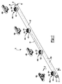
最初に図1を参照すると、本発明の一実施の形態に従った、被覆された髄内(IM)釘を形成するために使用され得る型が示されており、全体として参照数字10で特定されている。型10は、挿入端14及び対向端16を有するチューブ状部材12を、含み得る。図示されている本実施の形態では、挿入端14は、開口を規定している一方で、対向端16は、閉鎖端22を提供している。図示されている本実施の形態では、閉鎖端22は、全体として凸状の外側表面24を、有し得る。チューブ状部材12は、全体として、長手方向軸30に沿って延在し得る。
Referring initially to FIG. 1, there is shown a mold that can be used to form a coated intramedullary (IM) nail according to one embodiment of the present invention, identified generally by the
引き続き図1を参照し、今、追加的に図2を参照すると、チューブ状部材12は、外側表面36と内側表面38とを有する側壁34を有し得る。図示されている実施の形態では、側壁34は円筒状であるが、他の断面も考えられる。側壁34は、全体的に、長手方向軸30に沿って、延在し得る。当該側壁34は、複数の入口40a、40b、40c、40dを、規定している。対応する複数のボス構造体42a、42b、42c及び42dが、当該側壁34上の外側表面36から、延在し得る。各ボス構造体42a、42b、42c及び42dは、それぞれ、ネジ部44a、44b、44c及び44dを、含み(incorporate)得る。入口40a、ボス42a及びネジ部44aは、集合的に第1のネジ切りされた入口48aを構成し得る。同様に、入口40b、ボス42b及びネジ部44bは、集合的に第2のネジ切りされた入口48bを規定し得る。入口40c、ボス42c及びネジ部44cは、集合的に第3のネジ切りされた入口48cを構成し得る。入口40d、ボス42d及びネジ部44dは、集合的に第4のネジ切りされた入口48dを構成し得る。一実施の形態において、ここに示されている特定のチューブ状部材12は、4つのネジ切りされた入口を含んでいるが、追加の、または、より少ない、ネジ切りされた入口がそこに含まれ得る、ということが理解され得る。更に、いくつかの、または、全ての、ネジ切りされた入口48a、48b、48c及び48dは、ネジ無しでも提供され得る。この点で、ここで後に理解されるように、流動性材料の供給装置に選択的に接続するように構成されている他の接続構造が、それぞれのボス42a、42b、42c及び/または42d上に、形成され得る、あるいは、含まれ得る。一連のネジ切りされたキャップ49a、49b、49c及び49dが、それぞれ、第1、第2、第3及び第4入口48a、48b、48c及び48dに、ネジ式に係合し得る。ここでは、「第1」、「第2」、「第3」及び「第4」の用語は、恣意的に使用されており、特別な使用の優先順位または順序を表示することは意図されていない、ということが理解されるであろう。
With continued reference to FIG. 1 and now with additional reference to FIG. 2, the
今、特に図2及び図3を参照して、チューブ状部材12の追加の特徴が、説明される。第1、第2及び第3突出部50a、50b及び50cが、それぞれ、側壁34の内側表面38上に形成され得る。図示されている実施の形態では、突出部50a、50b及び50cは、放射状に等距離の間隔で、内側表面38の周りに放射状に配置され得る。図示されている実施の形態では、当該突出部50a、50b及び50cは、互いに対して実質的に120°で配置されている。各突出部は、挿入端14(図1)と対向端16(図1)との間で、実質的にチューブ状部材12の長さに沿って延在し得る。3つの突出部が図示されているが、追加の、または、より少ない、突出部が含まれ得る、ということが理解される。一実施の形態によれば、突出部50a、50b及び50cは、それぞれ、長手方向軸30に向かって内側に延びている、長手方向に間が開けられた複数の尖端部材54a、54b及び54cを、含み得る。各尖端部材54a、54b及び54cは、それぞれ、釘係合表面(nail engaging surface)56a、56b及び56cを、有し得る。それぞれの釘係合表面56a、56b及び56cは、釘(髄内釘)60に係合するように、及び、当該釘60を長手方向軸30に沿って内側にオフセットするように、構成され得て、並びに、突出部50a、50b及び50cの残りの部分から、間隔が置かれ得る。後に説明されるように、突出部50a、50b及び50cは、結果物のセメントで被覆されたIM釘60’のセメントの表面において、1以上の換気溝62(図9)の形成を、容易にし得る。当該換気溝62は、セメントで被覆されたIM釘60’の移植の間における圧力の発生(build-up)を抑制し得る。
Additional features of the
今、具体的に図3を参照して、チューブ状部材12の追加の特徴が、説明される。第1、第2及び第3の複数の換気孔または換気口66a、66b及び66cが、側壁34を貫通して形成され得る。図示されている実施の形態では、換気口66a、66b及び66cの各列は、全体的に、隣接する突出部50a、50b及び50cの隣接する対の間に、位置付けられている。以下の議論から理解されるように、換気口66a、66b及び66cは、チューブ状部材12内における流動性材料の前進の間に、空気がチューブ状部材12を抜けることを許容するように、構成されている。
Additional features of the
チューブ状部材12は、シリコンのような、容易に切断可能な、透明または半透明の材料から、形成され得る。更に、当該材料は、柔軟であり得て、セメントからの取り外し(cement-releasing)の助けとなり得る。いくつかの実施の形態では、シリコンは、ワイヤメッシュのような強化構造を、有し得る。チューブ状部材12は、任意の寸法を有するIM釘(または他の補綴インプラント)の受容(recipt)に適応するためのあらゆる寸法に、形成され得る。更に、前述の内容で特定されているように、チューブ状部材12は、任意の長さを有するIM釘に適応するための長さに、切断され得る。
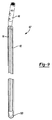
本開示の他の実施の形態によれば、引張部材80(図3)が、側壁34の内部に、または、側壁34に隣接して、含まれ得る。引張部材80は、チューブ状部材12の側壁34の長さに沿って、部分的に、または、完全に、延在し得る。当該引張部材80は、IM釘に対する流動性材料の硬化の後に、チューブ状部材12の除去を容易にするように、構成され得る。この点において、引張部材80は、ループまたは他の容易に把持可能な形態としての引張構造82を、含み得る。ユーザは、引張構造82を長手方向軸30から全体的に引き離すように引っ張り得て、チューブ状部材12の側壁34の長さに沿って、及び、長さを通じて、切れ目またはスリットを生成する。ひとたびチューブ状部材12に沿ってスリットが形成されると、ユーザは、被覆されたIM釘60’を現すために、チューブ状部材12を容易に引き剥がし得る。
According to other embodiments of the present disclosure, a tension member 80 (FIG. 3) can be included within or adjacent to the
今、特に図4乃至図7を参照して、本発明の一実施の形態によるIM釘60を被覆する方法が、説明される。本開示によれば、様々な内径及び外径を有する多数の型10が、提供される。ユーザは、任意の応用のための特定の釘60に適合する適切な型10を、選択し得る。型10の全体の長さは、例えば挿入端14のある長さを切断することによって変更され得る、ということが理解されるであろう。
Now, with particular reference to FIGS. 4-7, a method of coating an
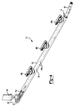
最初に、図4に示されているように、IM釘60は、チューブ状部材12の内部に導入され得る。次に、ネジ切りされたキャップの1つ、例えば49d、がそのネジ切りされた入口、例えばネジ切りされた入口48d、から除去され得る。流動性材料の供給装置100が、ネジ切りされた入口48dに接続され得る。次に、ユーザは、入口40dを介して、チューブ状部材12の内部に、流動性材料102を前進させ得る。図示されている実施の形態では、流動性材料の供給装置100は、ハンドル108(図5)を含み得る。当該ハンドル108は、供給装置100から出て入口40d内へ入る流動性材料102の排出に影響を及ぼすために、作動され得る。他の形態の流動性材料の供給装置も、使用され得る。更に、流動性材料の供給装置100とそれぞれの入口との間で、他の接続もなされ得る、ということが理解されるであろう。例えば、ルアーロック接続、ノズル接続または他の接続が、採用され得る。
Initially,
ユーザは、流動性材料102が、隣接する入口40cに向かってチューブ状部材12の一部に沿って十分に前進するまで、当該流動性材料102を導入し続け得る。チューブ状部材12は透明材料によって形成されているため、ユーザは、(側壁34の内側表面38とIM釘60との間を)チューブ状部材12の長さに沿って前進する流動性材料102を、監視し得る。一実施の形態では、流動性材料102が、隣接する入口40cに向かって、実質的に、例えば行程の約4分の3、前進したならば、ユーザは、チューブ状部材12の内部への流動性材料102の導入を、停止し得る。他の実施の形態も考慮される。
The user may continue to introduce the
次に、ユーザは、ネジ切りされた入口48dから流動性材料の供給装置100を取り外し得て、当該ネジ切りされた入口48dにキャップ49dを戻し得る。その後、キャップ49cが、隣接するネジ切りされた入口48cから取り外され得る。その後、流動性材料の供給装置100は、ネジ切りされた入口48cに接続される。次に、ユーザは、入口40cを介してチューブ状部材12の内部に、流動性材料102を促す。特には、流動性材料102は、第4入口48dに向かって埋め戻し得るのと同様に、第2のネジ切りされた入口48bに向かって反対方向に前進し得る。理解され得るように、流動性材料102は第4入口48dに向かって埋め戻すので、当該流動性材料は、第4のネジ切りされた入口48dと第3のネジ切りされた入口48cとの間のIM釘60に沿って、均等に広がることになる。
The user can then remove the flowable
前記プロセスは、IM釘60の長さに沿って流動性材料102が十分に覆うまで、チューブ状部材12の長さに沿って後続する入口に対して、繰り返される。いくつかの実施の形態では、必要ではないが、流動性材料は、換気口66a、66b及び66cのいくつかから、または、それらの全てから、外へ広がり得る、ということが理解されるであろう。更に、換気口66a、66b及び66cは、チューブ状部材12の内部への流動性材料102の導入の間に、チューブ状部材12とIM釘60との間における流動性材料の導入に適応するべく、空気がチューブ状部材12から脱出することを、許容する。
The process is repeated for subsequent inlets along the length of the
図8を参照すると、追加の特徴に従って構築されたチューブ状部材12’が、示されている。チューブ状部材12’は、強化シリコン材料を含み得る。当該強化シリコン材料は、ワイヤメッシュ104を含み得る。他の強化構造も、含み得る。
Referring to FIG. 8, a tubular member 12 'constructed according to additional features is shown. Tubular member 12 'may comprise a reinforced silicon material. The reinforced silicon material can include a
特に図9を参照すると、ひとたび流動性材料102が十分に硬化されたならば、チューブ状部材12は、被覆されたIM釘60’から切除されて処分され得る。結果物の被覆されたIM釘60’は、そこに沿って形成されて長手方向に延びている溝62を、含み得る。当該溝62は、空気の逃げ(escape)に適応し得て、IM管内への移植中における圧力の上昇を防止し得る。本開示の更なる実施の形態によれば、チューブ状部材12の内部へのIM釘60の挿入に先立ち、薄膜状のシース120が、当該IM釘60の一端部に取り付けられ(incorporated)得る。シース120は、例えばそこへ曝されるカニュレーション(cannulation)を通じての、IM釘60の内部への流動性材料の導入を、防止し得る。追加的に、または、選択的に、例えば柔軟性があるシリコンによって形成された、プラグまたはプラグの集団が、IM釘60の内部への流動性材料の導入を防止するために、ネジ切りされた孔、または、釘(IM釘)のカニューレ、の中へ導入され得る
前述の複数の実施の形態の説明は、例示及び説明の目的のために提供されている。網羅的であること、及び、開示を限定することは、意図されていない。特定の実施の形態の個々の要素または特徴は、一般に、その特定の実施の形態に限定されておらず、適用可能であれば、明確に図示または説明されていない場合でさえ、当該個々の要素または特徴は、交換可能であり、選択された実施の形態で使用され得る。当該個々の要素または特徴はまた、数多くの手法で変形され得る。そのような変形例は、本開示から離れていると考えられるべきではなく、そのような変形例の全ては、本開示の範囲内に含まれることが、意図されている。
With particular reference to FIG. 9, once the
(用語の非限定的な検討)
ここで使用されている見出し(例えば「背景技術(Introduction)」及び「発明の概要(Summary)」)は、本開示における話題の全体的な構成のためにのみ意図されており、本技術及びそのあらゆる特徴の開示を限定することは意図されていない。特には、「背景技術」において開示されている主題事項は、新規の技術を含み得て、先行技術の説明を構成していない。「発明の概要」において開示されている主題事項は、本技術の全範囲の網羅的または完全な開示ではない、あるいは、そのあらゆる実施の形態はない。この明細書の一部における特定の有用性を有する材料の分類または議論は、便宜上行われており、それが任意の組成で使用される時に、当該材料が、ここでの当該分類に従って、必然的に、または、単独で、機能しなければならないという推論は、引き出されるべきではない。
(Non-limiting review of terminology)
The headings used herein (eg, “Introduction” and “Summary”) are intended only for the general composition of the topics in this disclosure, and the present technology and its It is not intended to limit the disclosure of any feature. In particular, the subject matter disclosed in "Background Art" may include new technology and does not constitute a description of prior art. The subject matter disclosed in the "Summary" is not an exhaustive or complete disclosure of the entire scope of the technology, or in any embodiment thereof. The classification or discussion of a material having a particular utility in this part of the specification is done for convenience, and when it is used in any composition, the material must be classified according to the classification here. The reasoning that it must function in isolation or by itself should not be drawn.
本明細書及び特定の実施の形態は、本技術の実施の形態を示しているが、説明の目的のみのために意図されており、本技術の範囲を限定することは意図されていない。更に、言及された特徴を有する多数の実施の形態の説明は、追加の特徴を有する他の実施の形態、または、言及された特徴の異なる組合せを含む他の実施の形態、を排除することは意図されていない。特定の実施の形態は、本技術の構成物及び方法をどのように製造及び使用するか、の例示的な目的のために提供されており、別に明確に述べられていない限り、本技術の任意の実施の形態が、製造または試験されている、あるいは、されていない、ということの表示(representation)であることは、意図されていない。 While the specification and specific embodiments illustrate embodiments of the technology, they are intended for purposes of illustration only and are not intended to limit the scope of the technology. Further, the description of a number of embodiments having the mentioned features does not exclude other embodiments having additional features or other embodiments that include different combinations of the mentioned features. Not intended. Certain embodiments are provided for exemplary purposes of how to make and use the technology's components and methods, and are optional for the technology, unless expressly stated otherwise. It is not intended that this embodiment be a representation that it has been manufactured, tested, or not.
ここで使用されているように、「所望する(desire)」または「所望される(所望され得る)(desirable)」の語は、ある状況下で、ある利益を与える、本技術の実施の形態を述べている。しかしながら、同一または他の状況下において、他の実施の形態もまた、所望され得る。更に、1以上の所望される実施の形態の説明は、他の実施の形態が有用ではないということを示しておらず、本技術の範囲から他の実施の形態を排除することは意図されていない。 As used herein, the word “desire” or “desirable” is an embodiment of the technology that provides a benefit under certain circumstances. States. However, other embodiments may also be desirable under the same or other circumstances. Furthermore, the description of one or more desired embodiments does not indicate that other embodiments are not useful, and is not intended to exclude other embodiments from the scope of the technology. Absent.
ここで使用されているように、「含む(含んでいる)(include)」の語及びその異形(variants)は、非限定的であることが意図されており、あるリスト内の項目の説明は、本技術の材料、組成、装置及び方法において有用であり得る他の同様の項目の排除のためのものではない。同様に、「可能である(can)」及び「し得る(may)」の語及びその異形は、一実施の形態が、ある要素または特徴を有することが可能である、または、有し得る、という説明が、それらの要素または特徴を含まない本技術の他の実施の形態を排除しないように、非限定的であることが意図されている。 As used herein, the term “include” and its variants are intended to be non-limiting, and descriptions of items in a list are not intended. It is not intended to exclude other similar items that may be useful in the materials, compositions, apparatus and methods of the present technology. Similarly, the words “can” and “may” and variations thereof may or may have one element or feature of an embodiment, Is intended to be non-limiting so as not to exclude other embodiments of the technology that do not include those elements or features.
含む(including)、含有している(containing)または、有する(having)等の非限定的な用語の類義語としての、制限がない用語「有する(有している)(comprising)」は、ここでは、本技術の実施の形態を説明及び主張するために使用されており、実施の形態は、代替的に、「から成る(consisting of)」または「から本質的に成る(consisting essentially of)」等のような、より限定的な用語を用いて、記述され得る。従って、材料、組成、またはプロセス工程を説明している任意の実施の形態に対して、本技術はまた、そのような追加の材料、組成またはプロセスは、本出願において明確には説明されていないものの、(から成る、については)追加の材料、組成またはプロセスを除外した材料、組成またはプロセス、及び、(から本質的に成る、については)実施の形態の顕著な特性に影響を及ぼす追加の材料、組成またはプロセスを除外した材料、組成またはプロセス、から成る、または、から本質的に成る、実施の形態も明確に含んでいる。例えば、要素A、B及びCを説明する組成またはプロセスの説明は、ここで要素Dが除外されていると明確に説明されていないとしても、本技術において説明され得る要素Dを排除してA、B、及びCから成る、または、それらから本質的に成る実施の形態を、明確に想定している。要素または層が、他の要素または層「の上に(on)」、「に係合されて(engaged to)」、「に接続されて(connected to)」または「に結合(接続)されて(coupled to)」いる(ある)と説明されている場合、それは、他の要素または層に、あるいは、存在し得る介在要素または介在層に対して、直接的に、上に、係合されて、接続されて、または、結合されて、いる(ある)。対照的に、要素が、他の要素または層「のすぐ上に(directly on)」、「に直接的に係合されて(directly engaged to)」、「に直接的に接続されて(directly connected to)」または、「に直接的に結合(接続)されて(directly coupled to)」いる(ある)場合には、介在要素または介在層は存在しない。複数の要素間の関係性を説明するために使用されている他の語は、同様に解釈されるべきである(例えば、「の間に(between)」に対する「の間に直接に(directly between)」、「隣接する(adjacent)」に対する「すぐに隣接する(directly adjacent)」等)。ここで使用されているように、「及び/または」の語は、関連する列挙された項目の1以上の任意の及び全ての組合せを、含んでいる。 The term “comprising”, as a synonym for a non-limiting term such as including, containing or having, is used herein to include Used to describe and claim embodiments of the technology, which may alternatively be “consisting of” or “consisting essentially of”, etc. May be described using more restrictive terms, such as Thus, for any embodiment describing materials, compositions, or process steps, the technology also does not explicitly describe such additional materials, compositions, or processes in this application. However, for (consisting of) additional materials, compositions or processes, excluding additional materials, compositions or processes, and (for consisting essentially of) additional features that affect the salient properties of the embodiment. Embodiments specifically consisting of, or consisting essentially of, materials, compositions or processes excluding materials, compositions or processes are also explicitly included. For example, a composition or process description that describes elements A, B, and C excludes element D, which may be described in the art, even though it is not specifically described herein as element D being excluded. Embodiments consisting of, or consisting essentially of,, B and C are clearly envisaged. An element or layer is “on”, “engaged to”, “connected to” or “connected” to another element or layer If it is described as being “coupled to”, it is engaged directly, on, to other elements or layers, or to any intervening elements or layers that may be present. , Connected, or coupled (is). In contrast, an element is directly connected to another element or layer “directly on”, “directly engaged to”, or “directly connected”. to ”or“ directly coupled to ”(present), there are no intervening elements or layers. Other terms used to describe the relationship between multiple elements should be construed in the same way (eg, “directly between” and “between”). ) "," Directly adjacent "to" adjacent ", etc.). As used herein, the term “and / or” includes any and all combinations of one or more of the associated listed items.
Claims (12)
チューブ状部材内へ、当該チューブ状部材の挿入端から当該チューブ状部材の対向端に向かって、前記IM釘を前進させる工程と、
前記チューブ状部材上の第1位置において側壁を貫通して規定されている第1入口を介して、流動性材料を前進させる工程と、
前記流動性材料の硬化後に、当該硬化された流動性材料をその上に有する前記IM釘から、前記チューブ状部材を取り除く工程と、
を備え、
前記IM釘を前進させる工程は、前記チューブ状部材の前記側壁の内側円筒表面上に形成されて長手方向に延びている少なくとも2つの突出部に沿って、前記IM釘を摺動させて移す工程を有する
ことを特徴とする方法。 A method of coating an intramedullary (IM) nail with a flowable material comprising:
A step of advancing the IM nail into the tubular member from the insertion end of the tubular member toward the opposing end of the tubular member;
Advancing the flowable material through a first inlet defined through a side wall at a first position on the tubular member;
Removing the tubular member from the IM nail having the cured flowable material thereon after curing the flowable material;
Equipped with a,
The step of advancing the IM nail is a step of sliding the IM nail along at least two protrusions formed on the inner cylindrical surface of the side wall of the tubular member and extending in the longitudinal direction. wherein the <br/> to have.
ことを特徴とする請求項1に記載の方法。 The step of advancing the IM nail includes the step of advancing the IM nail into the tubular member until the tip of the IM nail engages the concave surface at the opposite end of the tubular member. The method of claim 1 wherein:
を更に備えたことを特徴とする請求項1に記載の方法。 The method according to claim 1 , further comprising connecting a flowable material supply device to a boss formed on the tubular member in proximity to the first inlet.
ことを特徴とする請求項3に記載の方法。 The connecting step includes one of a step of connecting the flowable material supply device to the tubular member in a screw type, a step of connecting in a luer lock type, and a step of connecting in a nozzle type. 4. A method according to claim 3 , comprising:
を更に備えたことを特徴とする請求項1に記載の方法。 The method further comprises advancing the flowable material through a second inlet defined through the side wall at a second position different from the first position on the tubular member. The method of claim 1 .
実質的に前記第2入口に向かって前進している前記流動性材料に基づいて、前記第1入口を介しての当該流動性材料の当該前進を停止させる工程と、
を更に備えたことを特徴とする請求項5に記載の方法。 Monitoring the flowable material advancing inside the tubular member;
Stopping the advancement of the flowable material through the first inlet based on the flowable material being substantially advanced toward the second inlet;
6. The method of claim 5 , further comprising:
ことを特徴とする請求項1に記載の方法。 Removing the tubular member A method according to claim 1, characterized in that the step of removing from the IM nail coated by cutting the tubular member, comprise.
ことを特徴とする請求項1に記載の方法。 Removing the tubular member, according to claim 1, characterized in that it includes the step of pulling the tensile member disposed on the tubular member to form a slit along the tubular member, the the method of.
を更に備えたことを特徴とする請求項1に記載の方法。 The method of claim 1 , further comprising placing a sheath on one end of the IM nail prior to advancing the IM nail into the tubular member.
チューブ状部材内へ、当該チューブ状部材の挿入端から当該チューブ状部材の対向端に向かって、前記IM釘の遠位端が前記チューブ状部材の前記対向端における凹表面に係合するまで前記IM釘を前進させる工程と、 Into the tubular member, from the insertion end of the tubular member toward the opposing end of the tubular member until the distal end of the IM nail engages the concave surface at the opposing end of the tubular member A step of advancing the IM nail;
前記チューブ状部材上の第1位置において側壁を貫通して規定されている第1入口を介して、流動性材料を前進させる工程と、Advancing the flowable material through a first inlet defined through a side wall at a first position on the tubular member;
前記流動性材料の硬化後に、当該硬化された流動性材料をその上に有する前記IM釘から、前記チューブ状部材を取り除く工程と、Removing the tubular member from the IM nail having the cured flowable material thereon after curing the flowable material;
を備えたWith
ことを特徴とする方法。A method characterized by that.
を更に備えたことを特徴とする請求項10に記載の方法。The method of claim 10, further comprising:
前記IM釘の一端上にシースを配置する工程と、Placing a sheath on one end of the IM nail;
チューブ状部材内へ、当該チューブ状部材の挿入端から当該チューブ状部材の対向端に向かって、前記IM釘を前進させる工程と、A step of advancing the IM nail into the tubular member from the insertion end of the tubular member toward the opposing end of the tubular member;
前記チューブ状部材上の第1位置において側壁を貫通して規定されている第1入口を介して、流動性材料を前進させる工程と、Advancing the flowable material through a first inlet defined through a side wall at a first position on the tubular member;
前記流動性材料の硬化後に、当該硬化された流動性材料をその上に有する前記IM釘から、前記チューブ状部材を取り除く工程と、Removing the tubular member from the IM nail having the cured flowable material thereon after curing the flowable material;
を備えたWith
ことを特徴とする方法。A method characterized by that.
Applications Claiming Priority (3)
| Application Number | Priority Date | Filing Date | Title |
|---|---|---|---|
| US13/547,331 US9017055B2 (en) | 2012-07-12 | 2012-07-12 | Device for coating intramedullary rods with cement |
| US13/547,331 | 2012-07-12 | ||
| PCT/US2013/050026 WO2014011843A2 (en) | 2012-07-12 | 2013-07-11 | Device for coating intramedullary rods with cement |
Related Child Applications (1)
| Application Number | Title | Priority Date | Filing Date |
|---|---|---|---|
| JP2016226221A Division JP6293243B2 (en) | 2012-07-12 | 2016-11-21 | Equipment for coating intramedullary nails with cement |
Publications (3)
| Publication Number | Publication Date |
|---|---|
| JP2015522359A JP2015522359A (en) | 2015-08-06 |
| JP2015522359A5 JP2015522359A5 (en) | 2016-10-13 |
| JP6047656B2 true JP6047656B2 (en) | 2016-12-21 |
Family
ID=48833082
Family Applications (2)
| Application Number | Title | Priority Date | Filing Date |
|---|---|---|---|
| JP2015521798A Expired - Fee Related JP6047656B2 (en) | 2012-07-12 | 2013-07-11 | Equipment for coating intramedullary nails with cement |
| JP2016226221A Expired - Fee Related JP6293243B2 (en) | 2012-07-12 | 2016-11-21 | Equipment for coating intramedullary nails with cement |
Family Applications After (1)
| Application Number | Title | Priority Date | Filing Date |
|---|---|---|---|
| JP2016226221A Expired - Fee Related JP6293243B2 (en) | 2012-07-12 | 2016-11-21 | Equipment for coating intramedullary nails with cement |
Country Status (7)
| Country | Link |
|---|---|
| US (2) | US9017055B2 (en) |
| EP (2) | EP2872307B1 (en) |
| JP (2) | JP6047656B2 (en) |
| CN (2) | CN104520089B (en) |
| AU (2) | AU2013290197B2 (en) |
| ES (1) | ES2631328T3 (en) |
| WO (1) | WO2014011843A2 (en) |
Families Citing this family (7)
| Publication number | Priority date | Publication date | Assignee | Title |
|---|---|---|---|---|
| US9017055B2 (en) * | 2012-07-12 | 2015-04-28 | Biomet Manufacturing, Llc | Device for coating intramedullary rods with cement |
| DE102013005414A1 (en) * | 2013-03-28 | 2014-10-02 | Dietmar Wolter | Osteosynthesis system for the multidirectional, angularly stable treatment of fractures of long bones including an intramedullary nail and bone screws |
| WO2019136122A1 (en) | 2018-01-03 | 2019-07-11 | Lee Thomas Hoon | Hybrid cannulated orthopedic screws |
| EP3740145A1 (en) | 2018-01-15 | 2020-11-25 | GLW, Inc. | Hybrid intramedullary rods |
| EP4385433A3 (en) | 2019-03-18 | 2024-09-11 | GLW, Inc. | Hybrid bone plate |
| CN111150475A (en) * | 2020-01-15 | 2020-05-15 | 中国人民解放军第四军医大学 | Bone cement intramedullary nail and preparation method thereof |
| USD969323S1 (en) | 2022-06-21 | 2022-11-08 | Mc Innovation Llc | Bone spacer mold system |
Family Cites Families (26)
| Publication number | Priority date | Publication date | Assignee | Title |
|---|---|---|---|---|
| JPH03223586A (en) * | 1990-01-29 | 1991-10-02 | Natl House Ind Co Ltd | Plaster covered pipe |
| US5098434A (en) | 1990-11-28 | 1992-03-24 | Boehringer Mannheim Corporation | Porous coated bone screw |
| CA2031571A1 (en) | 1990-12-05 | 1992-06-06 | The University Of British Columbia | Antibiotic loaded joint prosthesis |
| US5258098A (en) | 1991-06-17 | 1993-11-02 | Cycam, Inc. | Method of production of a surface adapted to promote adhesion |
| US5360448A (en) | 1991-10-07 | 1994-11-01 | Thramann Jeffrey J | Porous-coated bone screw for securing prosthesis |
| US5433718A (en) | 1992-08-20 | 1995-07-18 | Brinker; Mark | Antibiotic eluding intramedullary nail apparatus |
| US5716358A (en) | 1994-12-02 | 1998-02-10 | Johnson & Johnson Professional, Inc. | Directional bone fixation device |
| US5489306A (en) | 1995-01-03 | 1996-02-06 | Gorski; Jerrold M. | Graduated porosity implant for fibro-osseous integration |
| SE9701647D0 (en) | 1997-04-30 | 1997-04-30 | Nobel Biocare Ab | Calcium-phonsphate coated implant element |
| US6361731B1 (en) * | 1998-07-15 | 2002-03-26 | Biomet, Inc. | Method of forming a temporary implant |
| DE59914200D1 (en) | 1999-01-12 | 2007-03-29 | Lipat Consulting Ag | SURFACE STRUCTURE FOR A ENOSSAL IMPLANT |
| US6183255B1 (en) | 2000-03-27 | 2001-02-06 | Yoshiki Oshida | Titanium material implants |
| DE102004009429A1 (en) * | 2004-02-24 | 2005-09-22 | Biedermann Motech Gmbh | Bone anchoring element |
| ITVI20050049A1 (en) | 2005-02-22 | 2006-08-23 | Tecres Spa | DISPOSABLE DEVICE FOR THE TREATMENT OF INFECTION OF ARTS OF THE HUMAN BODY, PARTICULARLY OF ARTS WITH LONG BONES |
| US9452001B2 (en) | 2005-02-22 | 2016-09-27 | Tecres S.P.A. | Disposable device for treatment of infections of human limbs |
| CA2625264C (en) | 2005-10-13 | 2015-12-15 | Synthes (U.S.A.) | Drug-impregnated sleeve for a medical implant |
| EP2166970B1 (en) * | 2007-06-22 | 2016-09-21 | Epix Orthopaedics, Inc. | Intramedullary rod with pivotable fastener |
| GB0718417D0 (en) * | 2007-09-21 | 2007-10-31 | Depuy Int Ltd | Intramedullary rod instrument |
| CA2719033C (en) * | 2007-12-07 | 2014-07-08 | Zimmer Orthopaedic Surgical Products, Inc. | Spacer mold and methods therefor |
| US7637729B2 (en) | 2007-12-13 | 2009-12-29 | Biomet Manufacturing Corp. | Modular articulating cement spacer mold |
| WO2010088531A2 (en) | 2009-01-29 | 2010-08-05 | Smith & Nephew, Inc. | Low temperature encapsulate welding |
| CN101659130B (en) * | 2009-09-17 | 2011-08-17 | 周志海 | Molding mold of interlocking intramedullary nail |
| US8609003B2 (en) | 2010-10-12 | 2013-12-17 | Rahul Vaidya | Apparatus and method for forming an antibiotic impregnated bone cement intramedullary nail |
| KR101830799B1 (en) * | 2011-08-22 | 2018-02-22 | 삼성전자 주식회사 | Antenna device of a mobile terminal |
| US8961844B2 (en) | 2012-07-10 | 2015-02-24 | Nike, Inc. | Bead foam compression molding method for low density product |
| US9017055B2 (en) | 2012-07-12 | 2015-04-28 | Biomet Manufacturing, Llc | Device for coating intramedullary rods with cement |
-
2012
- 2012-07-12 US US13/547,331 patent/US9017055B2/en active Active
-
2013
- 2013-07-11 EP EP13739915.0A patent/EP2872307B1/en not_active Not-in-force
- 2013-07-11 AU AU2013290197A patent/AU2013290197B2/en not_active Ceased
- 2013-07-11 CN CN201380036818.2A patent/CN104520089B/en not_active Expired - Fee Related
- 2013-07-11 CN CN201710600108.8A patent/CN107521014B/en not_active Expired - Fee Related
- 2013-07-11 EP EP17150540.7A patent/EP3175963B1/en not_active Not-in-force
- 2013-07-11 ES ES13739915.0T patent/ES2631328T3/en active Active
- 2013-07-11 JP JP2015521798A patent/JP6047656B2/en not_active Expired - Fee Related
- 2013-07-11 WO PCT/US2013/050026 patent/WO2014011843A2/en active Application Filing
-
2015
- 2015-04-20 US US14/691,070 patent/US9440379B2/en active Active
-
2016
- 2016-11-21 JP JP2016226221A patent/JP6293243B2/en not_active Expired - Fee Related
-
2017
- 2017-01-31 AU AU2017200647A patent/AU2017200647B2/en not_active Ceased
Also Published As
| Publication number | Publication date |
|---|---|
| US20140017391A1 (en) | 2014-01-16 |
| EP2872307B1 (en) | 2017-01-18 |
| CN104520089B (en) | 2017-08-18 |
| AU2017200647A1 (en) | 2017-02-23 |
| WO2014011843A2 (en) | 2014-01-16 |
| US9440379B2 (en) | 2016-09-13 |
| CN104520089A (en) | 2015-04-15 |
| AU2013290197B2 (en) | 2016-11-24 |
| ES2631328T3 (en) | 2017-08-30 |
| US20150321389A1 (en) | 2015-11-12 |
| AU2017200647B2 (en) | 2017-06-08 |
| CN107521014A (en) | 2017-12-29 |
| US9017055B2 (en) | 2015-04-28 |
| EP2872307A2 (en) | 2015-05-20 |
| JP2015522359A (en) | 2015-08-06 |
| EP3175963B1 (en) | 2018-09-19 |
| CN107521014B (en) | 2019-11-22 |
| JP6293243B2 (en) | 2018-03-14 |
| EP3175963A1 (en) | 2017-06-07 |
| JP2017094087A (en) | 2017-06-01 |
| AU2013290197A1 (en) | 2015-01-22 |
| WO2014011843A3 (en) | 2014-02-27 |
Similar Documents
| Publication | Publication Date | Title |
|---|---|---|
| JP6293243B2 (en) | Equipment for coating intramedullary nails with cement | |
| DE69731741T2 (en) | URETHRAL DEVICE FOR RESTRAINING URIN | |
| KR101105647B1 (en) | Biological Decomposition Insertion Device for Muscle Strengthening | |
| EP2931180B1 (en) | Method and device for producing temporary knee joint spacers with stems of various sizes | |
| EP2522310B1 (en) | Mould for producing spacers for endoprosthetics | |
| JP2014500757A5 (en) | ||
| US20080243122A1 (en) | Apparatuses and methods for bone screw augmentation | |
| JP2006501967A (en) | Eccentric lumen stent | |
| US20160331428A1 (en) | Flexible bone dilator | |
| DE202018104602U1 (en) | protective sleeve | |
| US20220071677A1 (en) | Temporary Antimicrobial Cement Spacer, Assembly, Kit, And Method Of Manufacture | |
| IT202000020551A1 (en) | DEVICE FOR THE SELECTIVE BIOLOGICAL SYNTHESIS OF A BONE TISSUE | |
| DE102004041067A1 (en) | Method for applying a casing on a natural vessel section by means of a tubular auxiliary instrument | |
| DE202004020937U1 (en) | Method and device to place a jacket on a natural vessel particularly a vein whereby it is filled with fluid, inserted into application device using a tubular auxiliary instrument and jacket is deposited on vessel on pulling vessel out | |
| BRPI0805421B1 (en) | SCREW GUIDE FOR BONE STRUCTURE CEMENT |
Legal Events
| Date | Code | Title | Description |
|---|---|---|---|
| A521 | Written amendment |
Free format text: JAPANESE INTERMEDIATE CODE: A523 Effective date: 20150320 |
|
| A621 | Written request for application examination |
Free format text: JAPANESE INTERMEDIATE CODE: A621 Effective date: 20160711 |
|
| A521 | Written amendment |
Free format text: JAPANESE INTERMEDIATE CODE: A523 Effective date: 20160825 |
|
| A871 | Explanation of circumstances concerning accelerated examination |
Free format text: JAPANESE INTERMEDIATE CODE: A871 Effective date: 20160825 |
|
| A975 | Report on accelerated examination |
Free format text: JAPANESE INTERMEDIATE CODE: A971005 Effective date: 20160929 |
|
| TRDD | Decision of grant or rejection written | ||
| A01 | Written decision to grant a patent or to grant a registration (utility model) |
Free format text: JAPANESE INTERMEDIATE CODE: A01 Effective date: 20161021 |
|
| A61 | First payment of annual fees (during grant procedure) |
Free format text: JAPANESE INTERMEDIATE CODE: A61 Effective date: 20161121 |
|
| R150 | Certificate of patent or registration of utility model |
Ref document number: 6047656 Country of ref document: JP Free format text: JAPANESE INTERMEDIATE CODE: R150 |
|
| R250 | Receipt of annual fees |
Free format text: JAPANESE INTERMEDIATE CODE: R250 |
|
| LAPS | Cancellation because of no payment of annual fees |