EP3175802B1 - Medical instrument - Google Patents
Medical instrument Download PDFInfo
- Publication number
- EP3175802B1 EP3175802B1 EP16002431.1A EP16002431A EP3175802B1 EP 3175802 B1 EP3175802 B1 EP 3175802B1 EP 16002431 A EP16002431 A EP 16002431A EP 3175802 B1 EP3175802 B1 EP 3175802B1
- Authority
- EP
- European Patent Office
- Prior art keywords
- tool
- jaw part
- shank
- tool tip
- axially displaceable
- Prior art date
- Legal status (The legal status is an assumption and is not a legal conclusion. Google has not performed a legal analysis and makes no representation as to the accuracy of the status listed.)
- Active
Links
- 238000006073 displacement reaction Methods 0.000 claims description 9
- 230000007704 transition Effects 0.000 claims description 4
- 230000008878 coupling Effects 0.000 description 6
- 238000010168 coupling process Methods 0.000 description 6
- 238000005859 coupling reaction Methods 0.000 description 6
- 238000005452 bending Methods 0.000 description 3
- 238000010276 construction Methods 0.000 description 3
- 230000007246 mechanism Effects 0.000 description 3
- 230000005540 biological transmission Effects 0.000 description 1
- 230000015572 biosynthetic process Effects 0.000 description 1
- 230000000903 blocking effect Effects 0.000 description 1
- 230000007423 decrease Effects 0.000 description 1
- 230000000694 effects Effects 0.000 description 1
- 238000002674 endoscopic surgery Methods 0.000 description 1
- 230000036316 preload Effects 0.000 description 1
- 239000007787 solid Substances 0.000 description 1
Images


Classifications
-
- A—HUMAN NECESSITIES
- A61—MEDICAL OR VETERINARY SCIENCE; HYGIENE
- A61B—DIAGNOSIS; SURGERY; IDENTIFICATION
- A61B17/00—Surgical instruments, devices or methods, e.g. tourniquets
- A61B17/28—Surgical forceps
- A61B17/2812—Surgical forceps with a single pivotal connection
- A61B17/282—Jaws
-
- A—HUMAN NECESSITIES
- A61—MEDICAL OR VETERINARY SCIENCE; HYGIENE
- A61B—DIAGNOSIS; SURGERY; IDENTIFICATION
- A61B17/00—Surgical instruments, devices or methods, e.g. tourniquets
- A61B17/28—Surgical forceps
- A61B17/29—Forceps for use in minimally invasive surgery
-
- A—HUMAN NECESSITIES
- A61—MEDICAL OR VETERINARY SCIENCE; HYGIENE
- A61B—DIAGNOSIS; SURGERY; IDENTIFICATION
- A61B17/00—Surgical instruments, devices or methods, e.g. tourniquets
- A61B17/28—Surgical forceps
- A61B17/2812—Surgical forceps with a single pivotal connection
-
- A—HUMAN NECESSITIES
- A61—MEDICAL OR VETERINARY SCIENCE; HYGIENE
- A61B—DIAGNOSIS; SURGERY; IDENTIFICATION
- A61B17/00—Surgical instruments, devices or methods, e.g. tourniquets
- A61B17/28—Surgical forceps
- A61B17/2812—Surgical forceps with a single pivotal connection
- A61B17/2841—Handles
-
- F—MECHANICAL ENGINEERING; LIGHTING; HEATING; WEAPONS; BLASTING
- F16—ENGINEERING ELEMENTS AND UNITS; GENERAL MEASURES FOR PRODUCING AND MAINTAINING EFFECTIVE FUNCTIONING OF MACHINES OR INSTALLATIONS; THERMAL INSULATION IN GENERAL
- F16D—COUPLINGS FOR TRANSMITTING ROTATION; CLUTCHES; BRAKES
- F16D3/00—Yielding couplings, i.e. with means permitting movement between the connected parts during the drive
- F16D3/16—Universal joints in which flexibility is produced by means of pivots or sliding or rolling connecting parts
- F16D3/18—Universal joints in which flexibility is produced by means of pivots or sliding or rolling connecting parts the coupling parts (1) having slidably-interengaging teeth
-
- A—HUMAN NECESSITIES
- A61—MEDICAL OR VETERINARY SCIENCE; HYGIENE
- A61B—DIAGNOSIS; SURGERY; IDENTIFICATION
- A61B17/00—Surgical instruments, devices or methods, e.g. tourniquets
- A61B2017/00367—Details of actuation of instruments, e.g. relations between pushing buttons, or the like, and activation of the tool, working tip, or the like
- A61B2017/00371—Multiple actuation, e.g. pushing of two buttons, or two working tips becoming operational
-
- A—HUMAN NECESSITIES
- A61—MEDICAL OR VETERINARY SCIENCE; HYGIENE
- A61B—DIAGNOSIS; SURGERY; IDENTIFICATION
- A61B17/00—Surgical instruments, devices or methods, e.g. tourniquets
- A61B17/28—Surgical forceps
- A61B17/29—Forceps for use in minimally invasive surgery
- A61B2017/2901—Details of shaft
- A61B2017/2902—Details of shaft characterized by features of the actuating rod
-
- A—HUMAN NECESSITIES
- A61—MEDICAL OR VETERINARY SCIENCE; HYGIENE
- A61B—DIAGNOSIS; SURGERY; IDENTIFICATION
- A61B17/00—Surgical instruments, devices or methods, e.g. tourniquets
- A61B17/28—Surgical forceps
- A61B17/29—Forceps for use in minimally invasive surgery
- A61B2017/2926—Details of heads or jaws
- A61B2017/2927—Details of heads or jaws the angular position of the head being adjustable with respect to the shaft
- A61B2017/2929—Details of heads or jaws the angular position of the head being adjustable with respect to the shaft with a head rotatable about the longitudinal axis of the shaft
-
- A—HUMAN NECESSITIES
- A61—MEDICAL OR VETERINARY SCIENCE; HYGIENE
- A61B—DIAGNOSIS; SURGERY; IDENTIFICATION
- A61B17/00—Surgical instruments, devices or methods, e.g. tourniquets
- A61B17/28—Surgical forceps
- A61B17/29—Forceps for use in minimally invasive surgery
- A61B2017/2926—Details of heads or jaws
- A61B2017/2932—Transmission of forces to jaw members
- A61B2017/2933—Transmission of forces to jaw members camming or guiding means
- A61B2017/2936—Pins in guiding slots
Definitions
- a generic medical instrument is, for example, from DE 103 14 828 B3 known.
- a movement compensation element is provided which ensures that a rotation caused by the bending of the tool tip is compensated.
Description
Die Erfindung betrifft ein medizinisches Instrument mit einem hohlen Schaft, an dessen proximalem Ende eine Handhabe angeordnet ist und an dessen distalem Ende ein Werkzeug mit einem starren Maulteil sowie einem relativ zu dem starren Maulteil verschwenkbaren Maulteil angeordnet ist, wobei ein das Werkzeug tragender distaler Endbereich des Schaftes als gegenüber der Längsachse des Schaftes abwinkelbare Werkzeugspitze ausgebildet ist sowie das Werkzeug um die Längsachse des Schaftes bzw. um die Längsachse der Werkzeugspitze drehbar ist, wobei das Verdrehen des Werkzeugs um die Längsachse des Schaftes über eine in dem hohlen Schaft drehbar gelagerte Betätigungsstange erfolgt, die proximalseitig mit der Handhabe in Wirkverbindung steht und wobei das Abwinkeln der Werkzeugspitze über ein axialverschiebbar im hohlen Schaft gelagertes und proximalseitig mit der Handhabe in Wirkverbindung stehendes Betätigungselement erfolgt und wobei das verschwenkbare Maulteil des Werkzeugs über ein axialverschiebbar im hohlen Schaft gelagertes und proximalseitig mit der Handhabe in Wirkverbindung stehendes Betätigungselement zwischen einer geschlossenen und eine geöffneten Position verstellbar ist.The invention relates to a medical instrument with a hollow shaft, at the proximal end of which a handle is arranged and at the distal end of which a tool with a rigid jaw part and a jaw part pivotable relative to the rigid jaw part is arranged, with a distal end region carrying the tool The shaft is designed as a tool tip that can be bent with respect to the longitudinal axis of the shaft and the tool can be rotated about the longitudinal axis of the shaft or the longitudinal axis of the tool tip, with the tool being rotated about the longitudinal axis of the shaft via an actuating rod rotatably mounted in the hollow shaft, which is operatively connected to the handle on the proximal side and the angling of the tool tip takes place via an actuating element which is mounted axially displaceably in the hollow shaft and which is operatively connected to the handle on the proximal side, and the pivotable jaw part of the tool via an axialve The actuating element, which is slidably mounted in the hollow shaft and is operatively connected to the handle on the proximal side, can be adjusted between a closed and an open position.
Medizinische Instrumente für die endoskopische Chirurgie weisen in der Regel einem hohlen Schaft auf, an dessen proximalem Ende eine Handhabe und an dessen distalem Ende ein Werkzeug aus zwei relativ zueinander bewegbaren Maulteilen angeordnet ist. Das als Greif- ,Halte- und/oder Schneidinstrument ausgebildete Werkzeug ist über die Handhabe betätigbar. Um bei den häufig beengten Arbeitsverhältnissen mit dem Werkzeug einen möglichst großen Wirkungsbereich abdecken zu können, sind viele endoskopische Instrumente so ausgebildet, dass das Werkzeug gegenüber der Längsachse des Schaftes abwinkelbar ausgebildet ist sowie das Werkzeug um die Längsachse des Schaftes drehbar ist.Medical instruments for endoscopic surgery generally have a hollow shaft, at the proximal end of which a handle is arranged and at the distal end of which a tool consisting of two jaw parts that can be moved relative to one another is arranged. The tool, which is designed as a gripping, holding and / or cutting instrument, can be actuated via the handle. In order to be able to cover as large an effective area as possible with the tool in the often cramped working conditions, many endoscopic instruments are designed in such a way that the The tool is designed to be angled relative to the longitudinal axis of the shaft and the tool is rotatable about the longitudinal axis of the shaft.
Ein Problem bei den aus dem Stand der Technik bekannten medizinischen Instrumenten mit diesen vielfältigen Verstellmöglichkeiten der Werkzeugspitze und/oder des distalen Werkzeugs besteht darin, dass das Abwinkeln der Werkzeugspitze relativ zum proximalen Schaftbereich eine Zwangsbewegung der Maulteile relativ zueinander und/oder eine Rotationsbewegung der Werkzeugspitze zur Folge hat. Um diese Zwangsbewegung zu beheben, sind aus der Praxis verschiedene aufwendige Ausgleichsmechanismen bekannt. Diese Ausgleichsmechanismen gewährleisten zwar eine im Wesentlichen zwangsbewegungsfreie Abwinklung der Werkzeugspitze, jedoch ist der konstruktive Aufwand sehr groß und steht der insbesondere bei endoskopischen Instrumenten erforderlichen kompakten Bauweise entgegen.A problem with the medical instruments known from the prior art with these diverse adjustment possibilities of the tool tip and / or the distal tool is that the bending of the tool tip relative to the proximal shaft area causes a forced movement of the jaw parts relative to one another and / or a rotational movement of the tool tip towards the Consequence. In order to remedy this forced movement, various complex compensation mechanisms are known from practice. Although these compensating mechanisms ensure an angling of the tool tip that is essentially free of compulsory movement, the construction effort is very high and stands in the way of the compact construction required, in particular, for endoscopic instruments.
Ein gattungsgemäßes medizinisches Instrument ist beispielsweise aus der
Weitere alternative Mechanismen sind aus der
Davon ausgehend liegt der Erfindung die Aufgabe zugrunde, ein medizinisches Instrument der eingangs genannten Art zu schaffen, das bei kompakter Bauweise eine im Wesentlichen zwangsbewegungsfreie Abwinklung der Werkzeugspitze gewährleistet.Taking this as a starting point, the invention is based on the object of creating a medical instrument of the type mentioned at the outset which, with a compact design, ensures that the tool tip is bent in an essentially motion-free manner.
Die Lösung dieser Aufgabenstellung ist erfindungsgemäß durch die Merkmale von Anspruch 1 gekennzeichnet.The solution to this problem is characterized according to the invention by the features of
Durch die erfindungsgemäße Kopplung der Bewegungen des axialverschiebbaren Betätigungselements zum Abwinkeln der Werkzeugspitze mit der des axialverschiebbaren Betätigungselements zum Betätigen des verschwenkbaren Maulteils des Werkzeugs miteinander, wird die durch das Abwinkeln der Werkzeugspitze zwangsläufig bewirkte Verlagerung des starren Maulteils relativ zum verschwenkbaren Maulteil kompensiert, da nunmehr gleichzeitig das verschwenkbare Maulteil im gleichen Maße betätigt wird, was ein Beibehalten der eingestellten Position der Maulteile zueinander zur Folge hat.Due to the inventive coupling of the movements of the axially displaceable actuating element for angling the tool tip with that of the axially displaceable actuating element for actuating the pivotable jaw part of the tool with one another, the displacement of the rigid jaw part relative to the pivotable jaw part that is inevitably caused by the angling of the tool tip is compensated for, since the pivotable jaw part is actuated to the same extent, which means that the set position of the jaw parts is maintained in relation to one another.
Erfindungsgemäß wird vorgeschlagen, dass das axialverschiebbare Betätigungselement zum Abwinkeln der Werkzeugspitze und das axialverschiebbare Betätigungselement zum Betätigen des verschwenkbaren Maulteils des Werkzeugs in Richtung der Längsachse des Schaftes parallel zueinander angeordnet sind und den gleichen radialen Abstand zur Drehachse aufweisen, um die die Werkzeugspitze relativ zum proximalen Teil des Schaftes abwinkelbar ist. Durch den gleichen Abstand der beiden Betätigungselemente zur Drehachse wird gewährleistet, dass beide Betätigungselemente bei der gekoppelten gleichzeitigen Bewegung um die gleiche axiale Strecke verlagert werden.According to the invention, it is proposed that the axially displaceable actuating element for angling the tool tip and the axially displaceable actuating element for actuating the pivotable jaw part of the tool in the direction of the longitudinal axis of the shaft are arranged parallel to one another and have the same radial distance from the axis of rotation around which the tool tip relative to the proximal part of the shaft can be angled. The same distance between the two actuating elements and the axis of rotation ensures that both actuating elements are displaced by the same axial distance during the coupled simultaneous movement.
Weiterhin wird mit einer bevorzugten Ausführungsform der Erfindung vorgeschlagen, dass die Betätigungsstange zum Drehen des Werkzeugs zweiteilig ausgebildet aus einem in der abwinkelbaren Werkzeugspitze gelagerten distalen Teilbereich sowie einem im proximalen Teil des Schaftes gelagerten Teilbereich besteht, wobei die beiden einander zugewandten Stirnseiten der Teilbereiche der Betätigungsstange im Übergang zur abwinkelbaren Werkzeugspitze über stirnseitige Verzahnungen miteinander in Eingriff stehen. Der zweiteilige Aufbau der Betätigungsstange zum Drehen des Werkzeugs sowie die beiden stirnseitigen Verzahnung der beiden Teilbereiche der Betätigungsstange ermöglichen eine spielarme Übertragung der Drehbewegung vom Schaftbereich auf die Werkzeugspitze.Furthermore, it is proposed with a preferred embodiment of the invention that the actuating rod for rotating the tool is designed in two parts and consists of a distal sub-area mounted in the angled tool tip and a partial area mounted in the proximal part of the shaft, the two facing end faces of the partial areas of the actuating rod in the Transition to the angled tool tip are in engagement with one another via toothing on the face. The two-part construction of the actuating rod for rotating the tool and the two end-face teeth of the two partial areas of the actuating rod enable the rotational movement to be transmitted from the shaft area to the tool tip with little play.
Zur Kopplung des Werkzeugs mit dem distalen Teilbereiche der Betätigungsstange wird mit der Erfindung vorgeschlagen, dass das proximale Ende des verschwenkbaren Maulteils im Inneren des distalen Teilbereichs der um die Längsachse des Schaftes drehbaren Betätigungsstange gelagert ist und der distale Teilbereich der Betätigungsstange und das proximale Ende des verschwenkbaren Maulteils über einen die beiden Bauteile radial durchragenden Mitnahmestift kraftschlüssig so miteinander verbunden sind, dass der Mitnahmestift die Rotation des distalen Teilbereichs der Betätigungsstange direkt auf das verschwenkbare Maulteil überträgt.In order to couple the tool to the distal part of the actuating rod, the invention proposes that the proximal end of the pivotable jaw part is mounted inside the distal part of the actuating rod that is rotatable about the longitudinal axis of the shaft and that the distal part of the actuating rod and the proximal end of the pivotable The jaw part are non-positively connected to one another via a driver pin protruding radially through the two components so that the driver pin transmits the rotation of the distal portion of the actuating rod directly to the pivotable jaw part.
Gemäß einer praktischen Ausführungsform der Erfindung wird vorgeschlagen, dass die beiderseitigen freien Enden des Mitnahmestiftes in einem Schieber gelagert sind, der von der Rotation des distalen Teilbereichs der Betätigungsstange entkoppelt axialverschiebbar in der Werkzeugspitze gelagert ist.According to a practical embodiment of the invention, it is proposed that the free ends of the drive pin on both sides are mounted in a slide which is mounted in the tool tip so as to be axially displaceable and decoupled from the rotation of the distal portion of the actuating rod.
Zum Verstellen des verschwenkbaren Maulteils zwischen einer geschlossenen und einer offenen Position wird erfindungsgemäß vorgeschlagen, dass der Mitnahmestift so in dem Schieber gelagert ist, dass der Mitnahmestift in einer umlaufenden Nut des Schiebers frei um die Längsachse des Schaftes drehbar gelagert ist und in Richtung der Längsachse des Schaftes über den Schieber axialverschiebbar ist.To adjust the pivotable jaw part between a closed and an open position, it is proposed according to the invention that the driving pin is mounted in the slide in such a way that the driving pin is freely rotatable about the longitudinal axis of the shaft in a circumferential groove of the slide and in the direction of the longitudinal axis of the Shaft is axially displaceable via the slide.
Um die Bewegung des verschwenkbaren Maulteils von der Rotation der Werkzeugspitze zu entkoppeln, wird gemäß einer bevorzugten Ausführungsform der Erfindung vorgeschlagen, dass der Mitnahmestift im distalen Teilbereich der Betätigungsstange in einem Langloch gelagert ist, dessen axiale Erstreckung dem axialen Verschiebeweg des Schiebers entspricht.In order to decouple the movement of the pivotable jaw part from the rotation of the tool tip, it is proposed according to a preferred embodiment of the invention that the driving pin be mounted in an elongated hole in the distal part of the actuating rod, the axial extent of which corresponds to the axial displacement path of the slide.
Weiterhin wird mit der Erfindung vorgeschlagen, dass das axialverschiebbare Betätigungselement zum Betätigen des verschwenkbaren Maulteils des Werkzeugs und der Schieber so miteinander gekoppelt sind, dass eine Axialverschiebung des Betätigungselements spielfrei eine Axialbewegung des Schiebers bewirkt. Die Spielfreiheit der Maulteilbetätigung ist wichtig, damit der Operateur seine Krafteinleitung genau dosieren kann und ein stets sicherer Halt zwischen den Maulteilen des Werkzeugs gewährleistet ist.Furthermore, it is proposed with the invention that the axially displaceable actuating element for actuating the pivotable jaw part of the tool and the slide are coupled to one another in such a way that an axial displacement of the actuating element causes an axial movement of the slide without play. The freedom from play of the jaw part actuation is important so that the surgeon can precisely dose his force application and a secure hold between the jaw parts of the tool is guaranteed at all times.
Schließlich wird mit der Erfindung vorgeschlagen, dass die Zahnflanken der einzelnen Zähne der beiden stirnseitigen Verzahnungen sich radial nach außen verjüngend ausgebildet sind. Durch diese Ausbildung der Zahnflanken der einzelnen Zähne der beiden stirnseitigen Verzahnungen wird ohne Axialausgleich ein Verkanten der beiderseitigen Zähne der stirnseitigen Verzahnungen auch bei einem Verschwenken der stirnseitigen Verzahnungen relativ zueinander ausgeschlossen.Finally, it is proposed with the invention that the tooth flanks of the individual teeth of the two end-face toothings are designed to taper radially outward. This design of the tooth flanks of the individual teeth of the two front-side toothings prevents the teeth on both sides of the front-side toothings from tilting even when the front-side toothings are pivoted relative to one another without axial compensation.
Weitere Merkmale und Vorteile der Erfindung ergeben sich anhand der zugehörigen Zeichnungen, in denen ein Ausführungsbeispiel eines erfindungsgemäßen medizinischen Instruments nur beispielhaft dargestellt ist, ohne die Erfindung auf dieses Ausführungsbeispiel zu beschränken. In den Zeichnungen zeigt:
- Fig. 1
- eine perspektivische Seitenansicht eines erfindungsgemäßen medizinischen Instruments;
- Fig. 2
- einen Längsschnitt des Details II gemäß
Fig. 1 , eine nur teilweise abgewinkelte Position darstellend; - Fig. 3
- eine ausschnittweise Ansicht gemäß
Fig. 2 , jedoch den Längsschnitt in einer anderen vertikalen Ebene darstellend; - Fig. 4
- eine ausschnittweise Ansicht von unten des Details II gemäß
Fig. 1 ; - Fig. 5
- eine Ansicht von unten auf das Detail V gemäß
Fig. 2 und - Fig. 6
- eine perspektivische Ansicht einer stirnseitigen Verzahnung gemäß
Fig. 2 .
- Fig. 1
- a perspective side view of a medical instrument according to the invention;
- Fig. 2
- a longitudinal section of the detail II according to
Fig. 1 , showing an only partially angled position; - Fig. 3
- a detail view according to
Fig. 2 , but showing the longitudinal section in a different vertical plane; - Fig. 4
- a partial view from below of the detail II according to
Fig. 1 ; - Fig. 5
- a view from below of the detail V according to
Fig. 2 and - Fig. 6
- a perspective view of an end-face toothing according to FIG
Fig. 2 .
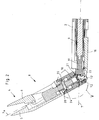
Die Abbildung
Um dem Werkzeug 4 möglichst viele Freiheitsgrade zur Bewegung relativ zum Schaft 2 einzuräumen, ist ein das Werkzeug 4 tragender distaler Endbereich des Schaftes 2 als gegenüber der Längsachse 7 des Schaftes 2 abwinkelbare Werkzeugspitze 8 ausgebildet. In der Darstellung gemäß
Weiterhin ist das Werkzeug 4 um die Längsachse 7 des Schaftes 2 bzw. bei abgewinkelter Werkzeugspitze 8 um die Längsachse 7a der Werkzeugspitze 8 drehbar, wobei das Verdrehen des Werkzeugs 4 um die Längsachse 7 des Schaftes 2 über eine in dem hohlen Schaft 2 drehbar gelagerte Betätigungsstange 9 erfolgt, die proximalseitig mit der Handhabe 3 in Wirkverbindung steht, wobei die Betätigungsstange 9 zweiteilig ausgebildet aus einem in der abwinkelbaren Werkzeugspitze 8 gelagerten distalen Teilbereich 10 sowie einem im proximalen Teil des Schaftes 2 gelagerten Teilbereich 11 besteht.Furthermore, the tool 4 can be rotated around the
Zur Ausbildung der Betätigungsstange 9 kann sowohl eine massive Stange als auch ein Hohlrohr verwendet werden.Both a solid rod and a hollow tube can be used to form the actuating
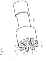
Die beiden einander zugewandten Stirnseiten der Teilbereiche 10 und 11 der Betätigungsstange 9 stehen im Übergang zur abwinkelbaren Werkzeugspitze 8 über stirnseitige Verzahnungen 12 miteinander in Eingriff, wie dies der schematischen Schnittdarstellung gemäß
Die Abbildung
Ein Hauptproblem bei der Ausbildung der beiden stirnseitigen Verzahnungen 12 der relativ zueinander verschwenkbaren Teilbereiche 10 und 11 der Betätigungsstange 9 besteht darin, ein gegenseitiges Verkanten und Blockieren einzelner Zähne 13 der stirnseitigen Verzahnungen 12 beim Verschwenken zu vermeiden.A main problem with the formation of the two end-
Bei der in den Abbildungen dargestellten Ausführungsform der stirnseitigen Verzahnungen 12 sind zusätzlich auch die Zahnflanken 14 der einzelnen Zähne 13 der beiden stirnseitigen Verzahnungen 12 sich radial nach innen verjüngend ausgebildet, wodurch die Bewegungsfreiheit der einzelnen Zähne 13 der beiden stirnseitigen Verzahnungen 12 relativ zueinander weiter erhöht wird.In the embodiment of the
Der perspektivischen Ansicht gemäß
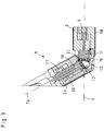
Neben dem verkantungsfreien Verschwenken der Werkzeugspitze 8 im Bereich der stirnseitigen Verzahnungen 12 besteht ein wesentliches Problem eines medizinischen Instruments 1 gemäß
Das Abwinkeln der Werkzeugspitze 8 erfolgt, wie aus der Abbildung
Das Verstellen des verschwenkbaren Maulteils 6 des Werkzeugs 4 zwischen einer geschlossenen und eine geöffneten Position erfolgt, wie aus der Abbildung
Zur Vermeidung der unerwünschten Zwangsbewegung des Werkzeugs 4 beim Abwinkeln der Werkzeugspitze 8 sind bei dem dargestellten medizinischen Instrument 1 das axialverschiebbare Betätigungselement 16 zum Abwinkeln der Werkzeugspitze 8 und das axialverschiebbare Betätigungselement 18 zum Betätigen des verschwenkbaren Maulteils 6 des Werkzeugs 4 derart miteinander gekoppelt, dass einerseits beim Betätigen des axialverschiebbaren Betätigungselements 16 zum Abwinkeln der Werkzeugspitze 8 zwangsläufig gleichzeitig das axialverschiebbare Betätigungselement 18 zum Betätigen des verschwenkbaren Maulteils 6 des Werkzeugs 4 in Axialrichtung bewegbar ist und andererseits das axialverschiebbare Betätigungselement 18 zum Betätigen des verschwenkbaren Maulteils 6 des Werkzeugs 4 unabhängig vom axialverschiebbaren Betätigungselement 16 zum Abwinkeln der Werkzeugspitze 8 betätigbar ist.In order to avoid the undesired forced movement of the tool 4 when the
Durch diese Kopplung der Bewegungen des axialverschiebbaren Betätigungselements 16 zum Abwinkeln der Werkzeugspitze 8 mit der des axialverschiebbaren Betätigungselements 18 zum Betätigen des verschwenkbaren Maulteils 6 des Werkzeugs 4 miteinander, wird die durch das Abwinkeln der Werkzeugspitze 8 zwangsläufig bewirkte Verlagerung des starren Maulteils 5 relativ zum verschwenkbaren Maulteil 6 kompensiert, da nunmehr gleichzeitig das verschwenbare Maulteil 6 im gleichen Maße betätigt wird, was ein Beibehalten der eingestellten Position der Maulteile 5 und 6 zueinander zur Folge hat.Through this coupling of the movements of the axially
Wie aus der Zusammenschau der Untenansicht gemäß der Abbildung
Aufgrund der parallelen Anordnung des axialverschiebbaren Betätigungselements 16 zum Abwinkeln der Werkzeugspitze 8 sowie des zugehörige Anlenkhebels 17 und des axialverschiebbaren Betätigungselements 18 zum Betätigen des verschwenkbaren Maulteils 6 des Werkzeugs 4 sowie des zugehörigen Anlenkhebels 19 und des gleichen radialen Abstands zur Drehachse 21 ist die Abwinklungsbewegung so abgestimmt, dass durch die Winkelbeziehung bzw. die Anordnung der Betätigungselemente 16 und 18 sowie der Anlenkhebel 17 und 19 die Maulteile 5 und 6 des Werkzeugs 4 ihre Position behalten. Die Kopplung der Betätigungselemente 16 und 18 sowie deren zuvor beschriebene konstruktiv geometrische Anordnung zueinander synchronisieren die Axialbewegungen der Betätigungselemente 16 und 18 und infolge dessen auch die Stellung der Maulteile 5 und 6 des Werkzeugs 4 zueinander.Due to the parallel arrangement of the axially
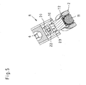
Die Übertragung der Bewegung des axialverschiebbaren Betätigungselements 18 zum Betätigen des verschwenkbaren Maulteils 6 des Werkzeugs 4 sowie des mit dem Betätigungselement 18 gekoppelten Anlenkhebels 19 auf das verschwenkbar Maulteil 6 erfolgt über den axialverschiebbar auf dem distalen Teilbereich 10 der Betätigungsstange 9 gelagerten Schieber 20, wie sich dies aus der nachfolgend beschriebenen Zusammenschau der Abbildungen
Das proximale Ende des verschwenkbaren Maulteils 6 ist im Inneren des distalen Teilbereichs 10 der um die Längsachse 7 des Schaftes 2 drehbaren Betätigungsstange 9 gelagert. Im Bereich des auf dem distalen Teilbereich 10 der Betätigungsstange 9 gelagerten Schiebers 20 durchragt ein Mitnahmestift 22 das proximale Ende des verschwenkbaren Maulteils 6 sowie den distalen Teilbereich 10 der Betätigungsstange 9 derart, dass die beiderseitigen freien Enden des Mitnahmestiftes 22 in dem Schieber 20 gelagert sind.The proximal end of the
Wie aus der Ansicht gemäß der Abbildung
Die Axialverschiebung des Betätigungselements 18 bewirkt somit über die gelenkige Kopplung an den Anlenkhebel 19 und den Schieber 20 eine axiale Verschiebung des Mitnahmestiftes 22 innerhalb des Langlochs 23. Aufgrund der kraftschlüssigen Kopplung des Mitnahmestiftes 22 mit dem proximalen Endes des verschwenkbaren Maulteils 6 ist so das verschwenkbare Maulteil 6 zwischen einer offenen und einer geschlossenen Position relativ zum starren Maulteil 5 verstellbar.The axial displacement of the
Der das proximale Ende des verschwenkbaren Maulteils 6 sowie den distalen Teilbereich 10 der Betätigungsstange 9 durchragende Mitnahmestift 22 verbindet die beiden Bauteile 10 und 6 kraftschlüssig so miteinander, dass der Mitnahmestift 22 die Rotation des distalen Teilbereichs 10 der Betätigungsstange 9 direkt auf das verschwenkbare Maulteil 6 überträgt, wenn der distale Teilbereich 10 der Betätigungsstange 9 unter Zwischenschaltung der stirnseitigen Verzahnungen 12 von dem im proximalen Teil des Schaftes 2 gelagerten Teilbereich 11 der Betätigungsstange 9 zu einer Rotation um die Längsachse 7 angetrieben wird.The driving
Um den axialverschiebar in der Werkzeugspitze 8 gelagerten Schieber 20 von der Rotation des distalen Teilbereichs 10 der Betätigungsstange 9 zu entkoppeln, ist der Mitnahmestift 22 frei um die Längsachse 7 des Schaftes 2 drehbar in einer umlaufenden Nut 24 des Schiebers 20 gelagert.In order to decouple the
Ein wie zuvor beschrieben aufgebautes medizinisches Instrument 1 zeichnet sich dadurch aus, dass eine im Wesentlichen zwangsbewegungsfreie Abwinklung der Werkzeugspitze 8 ohne Kompensationselemente möglich ist.A
- 11
- medizinisches Instrumentmedical instrument
- 22
- Schaftshaft
- 33
- HandhabeHandle
- 44th
- WerkzeugTool
- 55
- starres Maulteilrigid jaw
- 66th
- verschwenkbares Maulteilpivotable jaw part
- 77th
- Längsachse (Schaft)Longitudinal axis (shaft)
- 7a7a
- Längsachse (Werkzeugspitze)Longitudinal axis (tool tip)
- 88th
- WerkzeugspitzeTool tip
- 99
- BetätigungsstangeOperating rod
- 1010
- Teilbereich (distal)Partial area (distal)
- 1111
- Teilbereich (proximal)Partial area (proximal)
- 1212th
- stirnseitige Verzahnungfrontal toothing
- 1313th
- Zahntooth
- 1414th
- ZahnflankeTooth flank
- 1515th
- ZahnkopfTooth head
- 1616
- Betätigungselement (abwinkeln)Actuating element (bend)
- 1717th
- AnlenkhebelLinkage lever
- 1818th
- Betätigungselement (Maulteil)Actuating element (jaw part)
- 1919th
- AnlenkhebelLinkage lever
- 2020th
- SchieberSlider
- 2121
- DrehachseAxis of rotation
- 2222nd
- MitnahmestiftDriving pin
- 2323
- LanglochLong hole
- 2424
- NutGroove
Claims (8)
- Medical instrument with a hollow shank (2), at the proximal end of which a handle (3) is arranged, and at the distal end of which a tool (4) is arranged with a stationary jaw part (5) and with a jaw part (6) that is pivotable relative to the stationary jaw part (5), a distal end region of the shank (2) that carries the tool (4) being designed as a tool tip (8) that can be positioned at an angle with respect to the longitudinal axis (7) of the shank (2), and the tool (4) being rotatable about the longitudinal axis (7) of the shank (2) and/or about the longitudinal axis (7a) of the tool tip (8), the rotation of the tool (4) about the longitudinal axis (7) of the shank (2) being effected via an actuation rod (9) which is mounted rotatably in the hollow shank (2) and which is operatively connected at its proximal end to the handle (3), the tool tip (8) being positioned at an angle via an actuation element (16) which is mounted axially displaceably in the hollow shank (2) and which is operatively connected at its proximal end to the handle (3), and the pivotable jaw part (6) of the tool (4) being adjustable between a closed position and an open position via an actuation element (18) which is mounted axially displaceably in the hollow shank (2) and which is operatively connected at its proximal end to the handle (3),
characterized in that the axially displaceable actuation element (16) for positioning the tool tip (8) at an angle and the axially displaceable actuation element (18) for actuating the pivotable jaw part (6) of the tool (4) are coupled to each other in such a way that, on the one hand, when the axially displaceable actuation element (16) for positioning the tool tip (8) at an angle is actuated, the axially displaceable actuation element (18) for actuating the pivotable jaw part (6) of the tool (4) is necessarily movable at the same time in the axial direction so as to maintain the position of the jaw parts (5) and (6) relative to each other in the axial direction, and, on the other hand, the axially displaceable actuation element (18) for actuating the pivotable jaw part (6) of the tool (4) can be actuated independently of the axially displaceable actuation element (16) for positioning the tool tip (8) at an angle, the axially displaceable actuation element (16) for positioning the tool tip (8) at an angle and the axially displaceable actuation element (18) for actuating the pivotable jaw part (6) of the tool (4) being arranged parallel to each other in the direction of the longitudinal axis (7) of the shank (2) and being at the same radial distance from the rotation axis (21) about which the tool tip (8) can be positioned at an angle relative to the proximal part of the shank (2). - Medical instrument according to Claim 1, characterized in that the actuation rod (9) for rotating the tool (4) is composed of two parts, namely a distal sub-region (10) mounted in the pivotable tool tip (8) and a sub-region (11) mounted in the proximal part of the shank (2), and the two mutually facing end faces of the subregions (10 and 11) of the actuation rod (9) are in engagement with each other at the transition to • the pivotable tool tip (8) via end-face toothing arrangements (12).
- Medical instrument according to Claim 2, characterized in that the proximal end of the pivotable jaw part (6) is mounted in the interior of the distal sub-region (10) of the actuation rod (9) rotatable about the longitudinal axis (7) of the shank (2), and the distal sub-region (10) of the actuation rod (9) and the proximal end of the pivotable jaw part (6) are connected to each other with force-fit engagement via a driving pin (22) passing radially through the two components (10 and 6) such that the driving pin (22) transmits the rotation of the distal sub-region (10) of the actuation rod (9) directly to the pivotable jaw part (6).
- Medical instrument according to Claim 3, characterized in that the free ends on both sides of the driving pin (22) are mounted in a slide (20) which, decoupled from the rotation of the distal sub-region (10) of the actuation rod (9), is mounted axially displaceably in the tool tip (8) .
- Medical instrument according to Claim 4, characterized in that the driving pin (22) is mounted in the slide (20) such that the driving pin (22) is mounted in a circumferential groove (24) of the slide (20) so as to rotate freely about the longitudinal axis (7) of the shank (2) and is axially displaceable in the direction of the longitudinal axis (7) of the shank (2) via the slide (20).
- Medical instrument according to Claim 4 or 5, characterized in that the driving pin (22) is mounted in an oblong hole (23) in the distal sub• region (10) of the actuation rod (9), the axial extent of which oblong hole (23) corresponds to the axial displacement path of the slide (20).
- Medical instrument according to one of Claims 4 to 6, characterized in that the axially displaceable actuation element (18), for actuating the pivotable jaw part (6) of the tool (4), and the slide (20) are coupled to each other such that an axial displacement of the actuation element (18) causes an axial movement of the slide (20) free from play.
- Medical instrument according to one of Claims 2 to 7, characterized in that the tooth flanks (14) of the individual teeth (13) of the two end-face toothing arrangements (12) are designed tapering radially outwards.
Applications Claiming Priority (1)
| Application Number | Priority Date | Filing Date | Title |
|---|---|---|---|
| DE102015015655.1A DE102015015655A1 (en) | 2015-12-01 | 2015-12-01 | Medical instrument |
Publications (2)
| Publication Number | Publication Date |
|---|---|
| EP3175802A1 EP3175802A1 (en) | 2017-06-07 |
| EP3175802B1 true EP3175802B1 (en) | 2021-06-09 |
Family
ID=57345650
Family Applications (1)
| Application Number | Title | Priority Date | Filing Date |
|---|---|---|---|
| EP16002431.1A Active EP3175802B1 (en) | 2015-12-01 | 2016-11-16 | Medical instrument |
Country Status (3)
| Country | Link |
|---|---|
| US (1) | US10307178B2 (en) |
| EP (1) | EP3175802B1 (en) |
| DE (1) | DE102015015655A1 (en) |
Families Citing this family (6)
| Publication number | Priority date | Publication date | Assignee | Title |
|---|---|---|---|---|
| DE102016103640A1 (en) | 2016-03-01 | 2017-09-07 | Karl Storz Gmbh & Co. Kg | Medical instrument |
| EP3616637A1 (en) | 2018-08-29 | 2020-03-04 | Erbe Elektromedizin GmbH | Medical instrument |
| DE102019103493A1 (en) | 2019-02-12 | 2020-08-13 | Karl Storz Se & Co. Kg | Medical instrument |
| DE102019103489A1 (en) | 2019-02-12 | 2020-08-13 | Karl Storz Se & Co. Kg | Medical instrument |
| DE102020119462A1 (en) | 2020-07-23 | 2022-01-27 | Karl Storz Se & Co. Kg | MEDICAL INSTRUMENT |
| CN114129200B (en) * | 2021-12-07 | 2024-03-26 | 山东威瑞外科医用制品有限公司 | Clamp head handle |
Family Cites Families (26)
| Publication number | Priority date | Publication date | Assignee | Title |
|---|---|---|---|---|
| EP0526115B1 (en) * | 1991-07-29 | 1997-04-02 | Smith & Nephew Richards Inc | Forceps |
| US5514157A (en) * | 1992-02-12 | 1996-05-07 | United States Surgical Corporation | Articulating endoscopic surgical apparatus |
| US5431323A (en) * | 1992-10-09 | 1995-07-11 | Ethicon, Inc. | Endoscopic surgical instrument with pivotable and rotatable staple cartridge |
| US5330502A (en) * | 1992-10-09 | 1994-07-19 | Ethicon, Inc. | Rotational endoscopic mechanism with jointed drive mechanism |
| US5456684A (en) * | 1994-09-08 | 1995-10-10 | Hutchinson Technology Incorporated | Multifunctional minimally invasive surgical instrument |
| US5609601A (en) * | 1994-09-23 | 1997-03-11 | United States Surgical Corporation | Endoscopic surgical apparatus with rotation lock |
| US8241322B2 (en) * | 2005-07-27 | 2012-08-14 | Tyco Healthcare Group Lp | Surgical device |
| DE10036108A1 (en) * | 1999-09-09 | 2001-11-15 | Tuebingen Scient Surgical Prod | Surgical instrument for minimally invasive procedures |
| ATE363235T1 (en) * | 1999-09-09 | 2007-06-15 | Tuebingen Scient Medical Gmbh | SURGICAL INSTRUMENT FOR MINIMALLY INVASIVE PROCEDURES |
| WO2003013374A1 (en) * | 2001-08-06 | 2003-02-20 | Penn State Research Foundation | Multifunctional tool and method for minimally invasive surgery |
| US7476237B2 (en) * | 2003-02-27 | 2009-01-13 | Olympus Corporation | Surgical instrument |
| DE10314828B3 (en) | 2003-04-01 | 2004-07-22 | Tuebingen Scientific Surgical Products Gmbh | Surgical instrument for minimal invasive surgery with movement compensation element for compensation of rotation of effector upon pivot movement of instrument head |
| DE10330604A1 (en) * | 2003-04-01 | 2004-10-28 | Tuebingen Scientific Surgical Products Gmbh | Surgical instrument |
| WO2004112845A2 (en) * | 2003-06-17 | 2004-12-29 | Ethicon Endo-Surgery, Inc. | Surgical instrument having an increased range of motion |
| JP5357161B2 (en) * | 2007-09-21 | 2013-12-04 | コヴィディエン リミテッド パートナーシップ | Surgical equipment |
| US20090088770A1 (en) * | 2007-10-01 | 2009-04-02 | Warsaw Orthopedic, Inc. | Angled surgical drivers and methods of use |
| JP5535084B2 (en) * | 2008-01-10 | 2014-07-02 | コヴィディエン リミテッド パートナーシップ | Imaging system for a surgical device |
| US20090198272A1 (en) * | 2008-02-06 | 2009-08-06 | Lawrence Kerver | Method and apparatus for articulating the wrist of a laparoscopic grasping instrument |
| US8771260B2 (en) * | 2008-05-30 | 2014-07-08 | Ethicon Endo-Surgery, Inc. | Actuating and articulating surgical device |
| DE102011007119A1 (en) * | 2011-04-11 | 2012-10-11 | Karl Storz Gmbh & Co. Kg | Handling device for a micro-invasive-surgical instrument |
| DE102011007122A1 (en) * | 2011-04-11 | 2012-10-11 | Karl Storz Gmbh & Co. Kg | Tool for a micro-invasive-surgical instrument |
| DE102012007645A1 (en) * | 2012-04-18 | 2013-10-24 | Karl Storz Gmbh & Co. Kg | Medical instrument with bendable shaft |
| DE102012007648A1 (en) * | 2012-04-18 | 2013-10-24 | Karl Storz Gmbh & Co. Kg | Micro-invasive medical instrument |
| DE102014117393A1 (en) * | 2013-12-19 | 2015-06-25 | Karl Storz Gmbh & Co. Kg | Turnable and bendable medical instrument |
| DE102014203168A1 (en) * | 2014-02-21 | 2015-08-27 | Karl Storz Gmbh & Co.Kg | Instrument for performing medical interventions |
| US10292701B2 (en) * | 2014-06-25 | 2019-05-21 | Ethicon Llc | Articulation drive features for surgical stapler |
-
2015
- 2015-12-01 DE DE102015015655.1A patent/DE102015015655A1/en active Pending
-
2016
- 2016-11-16 EP EP16002431.1A patent/EP3175802B1/en active Active
- 2016-11-23 US US15/360,408 patent/US10307178B2/en active Active
Also Published As
| Publication number | Publication date |
|---|---|
| DE102015015655A1 (en) | 2017-06-01 |
| EP3175802A1 (en) | 2017-06-07 |
| US20170150982A1 (en) | 2017-06-01 |
| US10307178B2 (en) | 2019-06-04 |
Similar Documents
| Publication | Publication Date | Title |
|---|---|---|
| EP3175802B1 (en) | Medical instrument | |
| EP3772343B1 (en) | Medical instrument | |
| EP2869749B1 (en) | Medical instrument for pivoting such a medical instrument | |
| DE102012222755B4 (en) | Instrument, especially medical endoscopic instrument or technoscope | |
| DE102006003548B4 (en) | Pliers or scissors instrument with gearbox connection | |
| DE102009042490A1 (en) | control device | |
| EP3175801B1 (en) | Medical instrument | |
| DE102014205159A1 (en) | robot system | |
| DE4243715A1 (en) | Surgical instrument | |
| EP3351191B1 (en) | Surgical instrument, in particular for neurosurgery | |
| EP1721577B1 (en) | Endoscopic instrument | |
| EP1905369B1 (en) | Screwdriver for handling a screw in a human or animal body | |
| EP1629785B1 (en) | Medical forceps | |
| DE2752325A1 (en) | Endoscope distal end bending mechanism - has twin rack and pinion drives for tensioning wires and separate adjusting screws | |
| EP3250133B1 (en) | Shaft instrument for surgical purposes | |
| EP2601895B1 (en) | Medical instrument | |
| EP1365691B1 (en) | Medical instrument | |
| EP2403418B1 (en) | Medical instrument | |
| EP3943024B1 (en) | Medical instrument | |
| DE19703600C2 (en) | Medical instrument for endoscopic procedures | |
| EP2468193B1 (en) | Medical needle holder | |
| EP4178472B1 (en) | Surgical instrument, tool device for such a surgical instrument, and method for producing such a tool device | |
| EP3735919B1 (en) | Medical instrument | |
| EP2965698B1 (en) | Endoscopic instrument | |
| DE202007001075U1 (en) | Surgical instrument e.g. for spreading tissue, has two sides which by means of hinge are tiltably connected with second valve is adjustably provided in longitudinal axis |
Legal Events
| Date | Code | Title | Description |
|---|---|---|---|
| AK | Designated contracting states |
Kind code of ref document: A1 Designated state(s): AL AT BE BG CH CY CZ DE DK EE ES FI FR GB GR HR HU IE IS IT LI LT LU LV MC MK MT NL NO PL PT RO RS SE SI SK SM TR |
|
| AX | Request for extension of the european patent |
Extension state: BA ME |
|
| PUAI | Public reference made under article 153(3) epc to a published international application that has entered the european phase |
Free format text: ORIGINAL CODE: 0009012 |
|
| STAA | Information on the status of an ep patent application or granted ep patent |
Free format text: STATUS: THE APPLICATION HAS BEEN PUBLISHED |
|
| STAA | Information on the status of an ep patent application or granted ep patent |
Free format text: STATUS: REQUEST FOR EXAMINATION WAS MADE |
|
| 17P | Request for examination filed |
Effective date: 20170905 |
|
| RBV | Designated contracting states (corrected) |
Designated state(s): AL AT BE BG CH CY CZ DE DK EE ES FI FR GB GR HR HU IE IS IT LI LT LU LV MC MK MT NL NO PL PT RO RS SE SI SK SM TR |
|
| RAP1 | Party data changed (applicant data changed or rights of an application transferred) |
Owner name: KARL STORZ SE & CO. KG |
|
| GRAP | Despatch of communication of intention to grant a patent |
Free format text: ORIGINAL CODE: EPIDOSNIGR1 |
|
| STAA | Information on the status of an ep patent application or granted ep patent |
Free format text: STATUS: GRANT OF PATENT IS INTENDED |
|
| RIC1 | Information provided on ipc code assigned before grant |
Ipc: F16D 3/18 20060101ALN20210216BHEP Ipc: A61B 17/29 20060101AFI20210216BHEP |
|
| INTG | Intention to grant announced |
Effective date: 20210305 |
|
| GRAS | Grant fee paid |
Free format text: ORIGINAL CODE: EPIDOSNIGR3 |
|
| GRAA | (expected) grant |
Free format text: ORIGINAL CODE: 0009210 |
|
| STAA | Information on the status of an ep patent application or granted ep patent |
Free format text: STATUS: THE PATENT HAS BEEN GRANTED |
|
| AK | Designated contracting states |
Kind code of ref document: B1 Designated state(s): AL AT BE BG CH CY CZ DE DK EE ES FI FR GB GR HR HU IE IS IT LI LT LU LV MC MK MT NL NO PL PT RO RS SE SI SK SM TR |
|
| REG | Reference to a national code |
Ref country code: GB Ref legal event code: FG4D Free format text: NOT ENGLISH |
|
| REG | Reference to a national code |
Ref country code: CH Ref legal event code: EP Ref country code: AT Ref legal event code: REF Ref document number: 1399834 Country of ref document: AT Kind code of ref document: T Effective date: 20210615 |
|
| REG | Reference to a national code |
Ref country code: DE Ref legal event code: R096 Ref document number: 502016013168 Country of ref document: DE |
|
| REG | Reference to a national code |
Ref country code: IE Ref legal event code: FG4D Free format text: LANGUAGE OF EP DOCUMENT: GERMAN |
|
| REG | Reference to a national code |
Ref country code: LT Ref legal event code: MG9D |
|
| PG25 | Lapsed in a contracting state [announced via postgrant information from national office to epo] |
Ref country code: FI Free format text: LAPSE BECAUSE OF FAILURE TO SUBMIT A TRANSLATION OF THE DESCRIPTION OR TO PAY THE FEE WITHIN THE PRESCRIBED TIME-LIMIT Effective date: 20210609 Ref country code: LT Free format text: LAPSE BECAUSE OF FAILURE TO SUBMIT A TRANSLATION OF THE DESCRIPTION OR TO PAY THE FEE WITHIN THE PRESCRIBED TIME-LIMIT Effective date: 20210609 Ref country code: BG Free format text: LAPSE BECAUSE OF FAILURE TO SUBMIT A TRANSLATION OF THE DESCRIPTION OR TO PAY THE FEE WITHIN THE PRESCRIBED TIME-LIMIT Effective date: 20210909 Ref country code: HR Free format text: LAPSE BECAUSE OF FAILURE TO SUBMIT A TRANSLATION OF THE DESCRIPTION OR TO PAY THE FEE WITHIN THE PRESCRIBED TIME-LIMIT Effective date: 20210609 |
|
| REG | Reference to a national code |
Ref country code: NL Ref legal event code: MP Effective date: 20210609 |
|
| PG25 | Lapsed in a contracting state [announced via postgrant information from national office to epo] |
Ref country code: LV Free format text: LAPSE BECAUSE OF FAILURE TO SUBMIT A TRANSLATION OF THE DESCRIPTION OR TO PAY THE FEE WITHIN THE PRESCRIBED TIME-LIMIT Effective date: 20210609 Ref country code: GR Free format text: LAPSE BECAUSE OF FAILURE TO SUBMIT A TRANSLATION OF THE DESCRIPTION OR TO PAY THE FEE WITHIN THE PRESCRIBED TIME-LIMIT Effective date: 20210910 Ref country code: NO Free format text: LAPSE BECAUSE OF FAILURE TO SUBMIT A TRANSLATION OF THE DESCRIPTION OR TO PAY THE FEE WITHIN THE PRESCRIBED TIME-LIMIT Effective date: 20210909 Ref country code: SE Free format text: LAPSE BECAUSE OF FAILURE TO SUBMIT A TRANSLATION OF THE DESCRIPTION OR TO PAY THE FEE WITHIN THE PRESCRIBED TIME-LIMIT Effective date: 20210609 Ref country code: RS Free format text: LAPSE BECAUSE OF FAILURE TO SUBMIT A TRANSLATION OF THE DESCRIPTION OR TO PAY THE FEE WITHIN THE PRESCRIBED TIME-LIMIT Effective date: 20210609 |
|
| PG25 | Lapsed in a contracting state [announced via postgrant information from national office to epo] |
Ref country code: PT Free format text: LAPSE BECAUSE OF FAILURE TO SUBMIT A TRANSLATION OF THE DESCRIPTION OR TO PAY THE FEE WITHIN THE PRESCRIBED TIME-LIMIT Effective date: 20211011 Ref country code: RO Free format text: LAPSE BECAUSE OF FAILURE TO SUBMIT A TRANSLATION OF THE DESCRIPTION OR TO PAY THE FEE WITHIN THE PRESCRIBED TIME-LIMIT Effective date: 20210609 Ref country code: NL Free format text: LAPSE BECAUSE OF FAILURE TO SUBMIT A TRANSLATION OF THE DESCRIPTION OR TO PAY THE FEE WITHIN THE PRESCRIBED TIME-LIMIT Effective date: 20210609 Ref country code: ES Free format text: LAPSE BECAUSE OF FAILURE TO SUBMIT A TRANSLATION OF THE DESCRIPTION OR TO PAY THE FEE WITHIN THE PRESCRIBED TIME-LIMIT Effective date: 20210609 Ref country code: SM Free format text: LAPSE BECAUSE OF FAILURE TO SUBMIT A TRANSLATION OF THE DESCRIPTION OR TO PAY THE FEE WITHIN THE PRESCRIBED TIME-LIMIT Effective date: 20210609 Ref country code: SK Free format text: LAPSE BECAUSE OF FAILURE TO SUBMIT A TRANSLATION OF THE DESCRIPTION OR TO PAY THE FEE WITHIN THE PRESCRIBED TIME-LIMIT Effective date: 20210609 Ref country code: CZ Free format text: LAPSE BECAUSE OF FAILURE TO SUBMIT A TRANSLATION OF THE DESCRIPTION OR TO PAY THE FEE WITHIN THE PRESCRIBED TIME-LIMIT Effective date: 20210609 Ref country code: EE Free format text: LAPSE BECAUSE OF FAILURE TO SUBMIT A TRANSLATION OF THE DESCRIPTION OR TO PAY THE FEE WITHIN THE PRESCRIBED TIME-LIMIT Effective date: 20210609 |
|
| PG25 | Lapsed in a contracting state [announced via postgrant information from national office to epo] |
Ref country code: PL Free format text: LAPSE BECAUSE OF FAILURE TO SUBMIT A TRANSLATION OF THE DESCRIPTION OR TO PAY THE FEE WITHIN THE PRESCRIBED TIME-LIMIT Effective date: 20210609 |
|
| REG | Reference to a national code |
Ref country code: DE Ref legal event code: R097 Ref document number: 502016013168 Country of ref document: DE |
|
| PLBE | No opposition filed within time limit |
Free format text: ORIGINAL CODE: 0009261 |
|
| STAA | Information on the status of an ep patent application or granted ep patent |
Free format text: STATUS: NO OPPOSITION FILED WITHIN TIME LIMIT |
|
| PG25 | Lapsed in a contracting state [announced via postgrant information from national office to epo] |
Ref country code: DK Free format text: LAPSE BECAUSE OF FAILURE TO SUBMIT A TRANSLATION OF THE DESCRIPTION OR TO PAY THE FEE WITHIN THE PRESCRIBED TIME-LIMIT Effective date: 20210609 |
|
| 26N | No opposition filed |
Effective date: 20220310 |
|
| PG25 | Lapsed in a contracting state [announced via postgrant information from national office to epo] |
Ref country code: AL Free format text: LAPSE BECAUSE OF FAILURE TO SUBMIT A TRANSLATION OF THE DESCRIPTION OR TO PAY THE FEE WITHIN THE PRESCRIBED TIME-LIMIT Effective date: 20210609 |
|
| PG25 | Lapsed in a contracting state [announced via postgrant information from national office to epo] |
Ref country code: MC Free format text: LAPSE BECAUSE OF FAILURE TO SUBMIT A TRANSLATION OF THE DESCRIPTION OR TO PAY THE FEE WITHIN THE PRESCRIBED TIME-LIMIT Effective date: 20210609 |
|
| REG | Reference to a national code |
Ref country code: CH Ref legal event code: PL |
|
| PG25 | Lapsed in a contracting state [announced via postgrant information from national office to epo] |
Ref country code: LU Free format text: LAPSE BECAUSE OF NON-PAYMENT OF DUE FEES Effective date: 20211116 Ref country code: BE Free format text: LAPSE BECAUSE OF NON-PAYMENT OF DUE FEES Effective date: 20211130 |
|
| REG | Reference to a national code |
Ref country code: BE Ref legal event code: MM Effective date: 20211130 |
|
| PG25 | Lapsed in a contracting state [announced via postgrant information from national office to epo] |
Ref country code: LI Free format text: LAPSE BECAUSE OF NON-PAYMENT OF DUE FEES Effective date: 20211130 Ref country code: CH Free format text: LAPSE BECAUSE OF NON-PAYMENT OF DUE FEES Effective date: 20211130 |
|
| PG25 | Lapsed in a contracting state [announced via postgrant information from national office to epo] |
Ref country code: IE Free format text: LAPSE BECAUSE OF NON-PAYMENT OF DUE FEES Effective date: 20211116 |
|
| REG | Reference to a national code |
Ref country code: AT Ref legal event code: MM01 Ref document number: 1399834 Country of ref document: AT Kind code of ref document: T Effective date: 20211116 |
|
| PG25 | Lapsed in a contracting state [announced via postgrant information from national office to epo] |
Ref country code: AT Free format text: LAPSE BECAUSE OF NON-PAYMENT OF DUE FEES Effective date: 20211116 |
|
| PG25 | Lapsed in a contracting state [announced via postgrant information from national office to epo] |
Ref country code: HU Free format text: LAPSE BECAUSE OF FAILURE TO SUBMIT A TRANSLATION OF THE DESCRIPTION OR TO PAY THE FEE WITHIN THE PRESCRIBED TIME-LIMIT; INVALID AB INITIO Effective date: 20161116 |
|
| PG25 | Lapsed in a contracting state [announced via postgrant information from national office to epo] |
Ref country code: CY Free format text: LAPSE BECAUSE OF FAILURE TO SUBMIT A TRANSLATION OF THE DESCRIPTION OR TO PAY THE FEE WITHIN THE PRESCRIBED TIME-LIMIT Effective date: 20210609 |
|
| P01 | Opt-out of the competence of the unified patent court (upc) registered |
Effective date: 20230527 |
|
| PGFP | Annual fee paid to national office [announced via postgrant information from national office to epo] |
Ref country code: GB Payment date: 20231019 Year of fee payment: 8 |
|
| PGFP | Annual fee paid to national office [announced via postgrant information from national office to epo] |
Ref country code: IT Payment date: 20231019 Year of fee payment: 8 Ref country code: FR Payment date: 20231020 Year of fee payment: 8 Ref country code: DE Payment date: 20231019 Year of fee payment: 8 |