EP1629785B1 - Medical forceps - Google Patents
Medical forceps Download PDFInfo
- Publication number
- EP1629785B1 EP1629785B1 EP05017801A EP05017801A EP1629785B1 EP 1629785 B1 EP1629785 B1 EP 1629785B1 EP 05017801 A EP05017801 A EP 05017801A EP 05017801 A EP05017801 A EP 05017801A EP 1629785 B1 EP1629785 B1 EP 1629785B1
- Authority
- EP
- European Patent Office
- Prior art keywords
- movable
- slide
- grip part
- forceps
- handle
- Prior art date
- Legal status (The legal status is an assumption and is not a legal conclusion. Google has not performed a legal analysis and makes no representation as to the accuracy of the status listed.)
- Active
Links
- 230000005540 biological transmission Effects 0.000 claims description 64
- 230000033001 locomotion Effects 0.000 claims description 19
- 238000010009 beating Methods 0.000 claims 1
- 210000003811 finger Anatomy 0.000 description 4
- 241001465754 Metazoa Species 0.000 description 2
- 238000005520 cutting process Methods 0.000 description 2
- 238000004519 manufacturing process Methods 0.000 description 2
- 238000002324 minimally invasive surgery Methods 0.000 description 2
- 230000001154 acute effect Effects 0.000 description 1
- 230000000712 assembly Effects 0.000 description 1
- 238000000429 assembly Methods 0.000 description 1
- 230000008878 coupling Effects 0.000 description 1
- 238000010168 coupling process Methods 0.000 description 1
- 238000005859 coupling reaction Methods 0.000 description 1
- 239000012535 impurity Substances 0.000 description 1
- 238000003754 machining Methods 0.000 description 1
- 238000001356 surgical procedure Methods 0.000 description 1
- 210000003813 thumb Anatomy 0.000 description 1
Images


Classifications
-
- A—HUMAN NECESSITIES
- A61—MEDICAL OR VETERINARY SCIENCE; HYGIENE
- A61B—DIAGNOSIS; SURGERY; IDENTIFICATION
- A61B17/00—Surgical instruments, devices or methods, e.g. tourniquets
- A61B17/28—Surgical forceps
- A61B17/29—Forceps for use in minimally invasive surgery
- A61B17/2909—Handles
-
- A—HUMAN NECESSITIES
- A61—MEDICAL OR VETERINARY SCIENCE; HYGIENE
- A61B—DIAGNOSIS; SURGERY; IDENTIFICATION
- A61B17/00—Surgical instruments, devices or methods, e.g. tourniquets
- A61B17/28—Surgical forceps
- A61B17/29—Forceps for use in minimally invasive surgery
- A61B17/2909—Handles
- A61B2017/2912—Handles transmission of forces to actuating rod or piston
- A61B2017/2913—Handles transmission of forces to actuating rod or piston cams or guiding means
-
- A—HUMAN NECESSITIES
- A61—MEDICAL OR VETERINARY SCIENCE; HYGIENE
- A61B—DIAGNOSIS; SURGERY; IDENTIFICATION
- A61B17/00—Surgical instruments, devices or methods, e.g. tourniquets
- A61B17/28—Surgical forceps
- A61B17/29—Forceps for use in minimally invasive surgery
- A61B17/2909—Handles
- A61B2017/2912—Handles transmission of forces to actuating rod or piston
- A61B2017/2919—Handles transmission of forces to actuating rod or piston details of linkages or pivot points
Definitions
- the invention relates to a medical forceps as defined in the claims.
- a medical forceps is from the document US-A-6 077 290 known.
- a medical forceps of the type mentioned is used in particular in the context of minimally invasive surgery for interventions on the human or animal body.
- the medical forceps according to the present invention can be designed as grasping forceps for grasping tissue or as dissecting forceps for cutting or preparing tissue.
- Known medical forceps has a handle which has a movable handle part and a stationary handle part.
- the movable handle portion is pivotally mounted about a fixed pivot axis which is disposed at the handle facing away from the movable handle portion in a recess of a stationary housing part of the handle, which in turn is integrally connected to the immovable handle part.
- the immovable and the movable handle part are substantially transversely to the longitudinal axis of the shaft of this forceps and form a scissors-like arrangement.
- a force transmission element which is axially movable in the direction of the longitudinal axis of the shaft.
- the power transmission element which is in the form of a thin rod, serves to transmit power from the movable grip part to the movable tool, for example a jaw part, at the distal end of the shaft. Accordingly, the power transmission element with the movable tool on the one hand and the movable handle part on the other hand in operative connection.
- this operative connection is about made articulated intermediate piece, which in turn is pivotally mounted about a fixed pivot axis in the recess of the housing part, and with which the power transmission element is articulated at a point of articulation at a distance from the above-mentioned fixed pivot axis.
- the articulated intermediate piece is pivotally connected to the movable handle part via a pin which engages in a slot which is arranged on the movable handle part at a distance from the fixed pivot axis.
- a medical forceps in the form of a needle holder which has a handle with two movable handle parts, which together form the shape of a rod handle. Between the two movable handle parts, a slider is arranged, which is connected via a force limiting mechanism with the power transmission element.
- US-A-5,673,841 discloses a medical instrument, wherein the movable handle part is connected via a hinge lever with the power transmission element. With the shaft of the instrument another lever is pivotally connected to a pivot axis. The lever is pivotally connected to a linkage, which in turn is pivotally connected to a lever rod. The lever rod is axially slidably connected to the latter via a driver extending transversely to the force transmission element relative to the force transmission element.
- the movable handle part is pivotally mounted on the stationary handle part about a fixed pivot axis and has a handle side of the end of the movable handle portion protruding beyond the pivot axis projection on which the force transmission element is articulated directly. Since this extension executes a circular movement during pivoting of the movable handle part, again there is the disadvantage that the axially movable force transmission element performs a circular motion.
- DE-AS 1 055 751 a handle for surgical instruments, which has a fixed handle part and a movable handle part, which extend in contrast to the two aforementioned known medical forceps substantially in the axial extension of the shaft and form a handle assembly that resembles a forceps handle.
- the movable grip part is connected directly to a slide which is axially movable in the longitudinal direction of the force transmission element by a connecting pin.
- the slider takes up the instrument attachment.
- a leaf spring is connected between the two, which serves as a lever arm between the movable handle portion and the fixed handle portion.
- the invention has the object of developing a medical forceps of the type mentioned in such a way that the power transmission mechanism from the movable handle on the movable tool is possible free of play.
- this object is achieved with respect to the above-mentioned medical forceps in that the slide is offset in relation to the force transmission element transversely to the longitudinal axis of the shaft in the direction of the movable handle portion offset parallel and has a laterally projecting driver on which the force transmission element is set, wherein the gear of the power transmission mechanism is free of play from the movable handle part to the movable tool.
- the power transmission mechanism of the movable handle member on the power transmission element is thus designed so that the power transmission element, which should only perform an axial movement, as already mentioned, connected to a likewise purely axially movable slide, which is guided in a slide bearing fit.
- Known handle to connect the movable handle directly to the slider is provided in the inventive pliers that the slider is connected via a hinge lever with the movable handle part, wherein the hinge lever is articulated with one end on the slider and with another end on the movable handle part.
- the articulated lever is used to compensate for the difference in level between the articulation point on the movable handle part and the articulation point on the slide.
- the slide is arranged offset in parallel with respect to the force transmission element and has a laterally projecting carrier, on which the force transmission element is fixed.
- This embodiment is particularly advantageous when the handle assembly of the handle of the pliers is formed like a scissor handle.
- it can be avoided with the parallel offset arrangement of the slide with respect to the power transmission element, that the toggle lever with the slider forms an acute angle.
- the angle between the slide and the toggle lever can rather be chosen dull, for example, over 130 °, vorzua réelle about 150 °, whereby the light and backlash-free gear of the mechanism is improved.
- the handle has a stationary housing part, which has a recess open on one side, in which engages one end of the movable grip part and in which this end is pivotally mounted about the pivot axis, and the slide bearing for the slide closes the recess substantially ,
- the articulated intermediate piece is arranged in the recess of the housing part, the articulated intermediate piece only insufficiently closes the recess in this known pliers, since the articulated intermediate piece must indeed execute a movement when moving the movable grip part.
- the sliding bearing of the pliers according to the invention is an immovable part and can therefore be designed in terms of its geometry so that it at least substantially closes the recess.
- the sliding bearing is designed as a separate component.
- An advantage of this measure is the easier manufacture of the pliers according to the invention, because the machining of the plain bearing can be done separately from the mechanical processing, for example, of the aforementioned housing part.
- the sliding bearing is adapted in terms of its shape so that it is flush with the edge of the recess of the housing part.
- the housing part on all sides substantially has a smooth surface free of projections, which also significantly improves the aesthetic appearance of the pliers according to the invention.
- the slide and / or the slide bearing has / have a length which is greater than the maximum movement path of the slide in the slide bearing.
- the articulated lever is articulated by means of a respective rivet on the slider and the movable handle part.
- connection of the articulated lever by means of rivets on the slider or the movable handle part advantageously contributes in addition to the backlash of the gear of the power transmission mechanism.
- the toggle lever is hinged at one end between two legs of a fork portion of the movable handle portion and at the other end between two legs of a fork portion of the slider.
- This measure also contributes advantageously to further improve the backlash of the gear of the power transmission mechanism, because the hinge lever, such as a small plate, can be tilted between the respective legs of the fork sections.
- the handle has an immovable grip part, wherein the movable and the immovable grip part substantially transversely to the longitudinal axis of the Stand off shafts and together form a scissor handle assembly.
- This physician-preferred handle arrangement is unlike that of the document DE-AS 1 055 751 Known handle only made possible by the power transmission mechanism according to the invention.
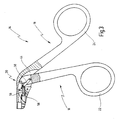
- a medical pliers provided with the general reference numeral 10 is shown. Forceps 10 are used in surgical procedures on the human or animal body, in particular in endoscope-assisted minimally invasive surgery.
- the forceps 10 has an elongated shaft 12 that has a small diameter so that the shaft 12 can be inserted through a narrow incision into the body of a patient.
- the forceps 10 has a handle 14.
- the handle 14 has a movable handle portion 16 and a stationary handle portion 18. Furthermore, the handle 14 has a housing part 20, which is preferably integrally connected to the immovable handle part 18.
- the movable grip part 16 has a finger ring 22 for inserting the index and / or middle finger, and the immovable grip part 18 also has a finger ring 24 for inserting the thumb.
- the forceps 10 At the distal end of the shaft 12, the forceps 10, a movable tool 26 and a stationary tool 28.
- the tool 28 may be movable as well as the tool 26.
- the tools 26 and 28 may cooperate in a cutting or grasping manner, depending on the intended use of the forceps 10.
- the movable handle portion 16 is pivotally mounted about a fixed pivot axis 30 on the housing part 20 of the handle 14. The pivoting of the movable handle portion 16 is used to move the movable tool 26.
- a power transmission element 32 is provided which in Fig. 1 is shown with broken lines.
- the power transmission element 32 such as a pull and push wire or rod, extends in the direction of the longitudinal axis of the shaft 12 and is axially movable relative thereto.
- the shaft 12 is formed as a tube, and the force transmission element 32 extends correspondingly in the interior of the shaft 12th
- the power transmission member 32 With one end 34, the power transmission member 32 is in operative connection with the movable tool 26, and with another end 36, the power transmission member 32 is in operative connection with the movable handle member 16, as hereinafter with reference to Fig. 2 to 4 will be described in more detail.
- the end 34 of the power transmission element 32 is connected to the movable tool 26, for example via a toggle lever assembly (not shown).
- Fig. 1 the movable tool 26 is shown in relation to the stationary tool 28 in its open position, in which the movable handle portion 16 is maximally spaced from the immovable handle portion 18.
- the movable tool By pivoting the movable handle portion 16 in the direction of an arrow 38 about the pivot axis 30 in the direction of the immovable handle portion 18, the movable tool through the mediation of the power transmission element 32 moves toward the stationary tool 28 through to its closed position.
- the handle parts 16 and 18 are approximated, but without abutting one another, as in Fig. 3 is shown, which shows the maximum approximate position of the handle parts 16 and 18.
- the grip members 16 and 18 are configured to project from the shaft 12 substantially transverse to the longitudinal axis of the shaft 12 and together form a scissor handle assembly.
- the housing part 20 of the handle 14 has at its distal end a bore 40 for receiving the proximal end of the shaft 12.
- a grub screw not shown for clamping the proximal end of the shaft 12 is screwed into the bore 40.
- the housing part 20, which is integrally connected to the immovable handle part 18, has a recess 44 which is open on one side and which is approximately crescent-shaped.
- the recess 44 is one-sided, on its side facing the movable handle part 16 open.
- a hinge lever 50 is articulated at one end to a pivot point 52 on the movable handle portion 16.
- the articulation point 52 is located in front of the pivot axis 30 with respect to the pivot axis 30 from the handling end (finger ring 22).
- the hinge lever 50 is articulated at its other end to a pivot point 54 on a slider 56 which is guided precisely in a slide bearing 58, the slider 56 is only linearly displaceable in the direction of the power transmission element 32.
- the sliding bearing 58 has a corresponding precisely fitting bore 60, which is, for example, a H7 bore, that is, a bore made with very small tolerances.
- the slider 56 is cylindrical and also manufactured with low tolerances. The slider 56 is mounted in the bore 60 of the sliding bearing 58 without radial play.
- Fig. 2 is the plain bearing 58, which is a separate component, inserted into the recess 44 of the housing part 20 and immovably fixed by means of two precisely fitting pins 63 and 64 on the housing part 20.
- the articulation point 54 of the articulated lever 50 on the slider 56 is also formed without play by a rivet.
- the slide bearing 58 is adapted in terms of its outer contour so that it substantially closes the recess 44 on the distal side of the movable grip part 16 and thereby terminates flush with the edge of the recess 44 of the housing part 20.
- the open side of the recess 44 is closed except for small open areas, which ensure the mobility of the movable grip part 16 in the recess 44.
- Fig. 2 shows the slider 56 in its maximum distal position, which corresponds to the open position of the tools 26, 28 and the maximum spaced position of the movable handle portion 16 from the stationary handle portion 18, and Fig. 3 shows the slider 56 in the maximum proximal position, which corresponds to the closed position of the tools 26, 28 and the maximum approximate position of the stationary handle portion 16 to the stationary handle portion 18.
- the slider 56 is offset relative to the power transmission element 32 in parallel and has a laterally projecting driver 66 which is fixedly connected to the slider 56.
- the driver 66 protrudes from an opening in the sliding bearing 58, wherein the driver 66 in cooperation with the edges of the opening 68th forms a stop for the maximum distal and the maximum proximal position of the slider 56 in the sliding bearing 58. In this way, the slider 56 is held captive in the sliding bearing 58.
- the maximum path of movement of the slider 56 in the sliding bearing 58 is thus determined by the axial width of the opening 68 in the sliding bearing 58 and by the axial width of the driver element 66.
- the length of the slider 56 and the length of the sliding bearing 58 and the bore 60 is selected to be greater than the maximum path of movement of the slider 56 in the sliding bearing 58th
- the force transmission element 32 is fixed with its end 36 at a coupling point 70 on the driver element 66.
- the articulated lever 50 forms with the slider 56 at an obtuse angle ⁇ (see. Fig. 4 ), which is made possible in particular by the parallel offset arrangement between the slider 56 and the power transmission element 32.
- Fig. 4 shows the movable handle portion 16 in the same position as in Fig. 2 , ie in the maximum of the immovable handle portion 18 spread open position.
- the articulation point 52 of the articulated lever 50 likewise executes a pivoting movement in the direction of an arrow 74.
- the toggle lever 50 exerts a pull on the slider 56, whereby the slider 56 is retracted in the direction of arrow 76.
- Due to the articulation of the articulated lever 50 on both the movable handle portion 16 and the slide 56 and its precise guide in the sliding bearing 58 act on the slider 56 is substantially no lateral forces, so that this smooth, purely linear movement in the bore 60 of the sliding bearing 58th performs.
- the power transmission element 32 is also purely axially in the direction of arrow 78 pulled proximally (in Fig. 2 and 3 the power transmission element 32 is not shown).
Description
Die Erfindung betrifft eine medizinische Zange wie in den Ansprüchen definiert.The invention relates to a medical forceps as defined in the claims.
Eine medizinische Zange ist aus dem Dokument
Eine medizinische Zange der eingangs genannten Art wird insbesondere im Rahmen der minimal-invasiven Chirurgie für Eingriffe am menschlichen oder tierischen Körper verwendet. Ohne Beschränkung der Allgemeinheit kann die medizinische Zange im Sinne der vorliegenden Erfindung als Fasszange zum Fassen von Gewebe oder als Präparierzange zum Schneiden bzw. Präparieren von Gewebe ausgebildet sein.A medical forceps of the type mentioned is used in particular in the context of minimally invasive surgery for interventions on the human or animal body. Without loss of generality, the medical forceps according to the present invention can be designed as grasping forceps for grasping tissue or as dissecting forceps for cutting or preparing tissue.
Eine aus dem Dokument
Im praktischen Gebrauch dieser medizinischen Zange hat sich herausgestellt, dass der Gang der Kraftübertragung vom beweglichen Griffteil auf das bewegliche Werkzeug trotz Beachtung geringster Toleranzen und sorgfältigster Fertigung nicht spielfrei ist. Dies hat den Nachteil, dass das bewegliche Werkzeug nicht exakt den Bewegungen des beweglichen Griffteils folgt. Ein weiterer Nachteil dieser bekannten medizinischen Zange besteht darin, dass der Anlenkungspunkt des axial beweglichen Kraftübertragungselements an dem gelenkigen Zwischenstück beim Betätigen des beweglichen Griffteils eine Kreisbewegung ausführt, was eine zusätzliche Bewegung des Kraftübertragungselements quer zur Längsrichtung des Schafts bedingt. Dies ist mitunter ein Grund dafür, dass diese Art von Kraftübertragungsmechanismus nicht vollständig spielfrei arbeitet.In the practical use of this medical forceps it has been found that the passage of the power transmission from the movable handle on the movable tool despite observance of the smallest tolerances and the most careful manufacturing is not backlash. This has the disadvantage that the movable tool does not exactly follow the movements of the movable handle part. Another disadvantage of this known medical forceps is that the point of articulation of the axially movable force transmission element on the articulated intermediate piece on actuation of the movable handle part performs a circular motion, which causes an additional movement of the force transmission element transverse to the longitudinal direction of the shaft. This is sometimes a reason that this type of power transmission mechanism does not work completely free of play.
Die aus dem eingangs genannten Dokument
Aus dem Dokument
In dem Dokument
In
Eine hinsichtlich der Kraftübertragungsmechanik vom beweglichen Griffteil auf das bewegliche Werkzeug besonders einfach ausgestaltete medizinische Zange ist aus dem Dokument
Bei dieser bekannten medizinischen Zange ist das bewegliche Griffteil am unbeweglichen Griffteil um eine feststehende Schwenkachse verschwenkbar befestigt und weist einen vom handhabungsseitigen Ende des beweglichen Griffteils aus gesehen über die Schwenkachse hinausragenden Fortsatz auf, an dem das Kraftübertragungselement unmittelbar angelenkt ist. Da dieser Fortsatz beim Verschwenken des beweglichen Griffteils eine Kreisbewegung ausführt, besteht auch hier wiederum der Nachteil, dass das axial bewegliche Kraftübertragungselement eine Kreisbewegung ausführt.In this known medical forceps, the movable handle part is pivotally mounted on the stationary handle part about a fixed pivot axis and has a handle side of the end of the movable handle portion protruding beyond the pivot axis projection on which the force transmission element is articulated directly. Since this extension executes a circular movement during pivoting of the movable handle part, again there is the disadvantage that the axially movable force transmission element performs a circular motion.
Schließlich offenbart das Dokument
Der Erfindung liegt die Aufgabe zugrunde, eine medizinische Zange der eingangs genannten Art dahingehend weiterzubilden, dass die Kraftübertragungsmechanik vom beweglichen Griffteil auf das bewegliche Werkzeug möglichst spielfrei ist.The invention has the object of developing a medical forceps of the type mentioned in such a way that the power transmission mechanism from the movable handle on the movable tool is possible free of play.
Erfindungsgemäß wird diese Aufgabe hinsichtlich der eingangs genannten medizinischen Zange dadurch gelöst, dass der Schieber in Bezug auf das Kraftübertragungselement quer zur Längsachse des Schafts in Richtung zum beweglichen Griffteil hin parallel versetzt angeordnet ist und einen seitlich abstehenden Mitnehmer aufweist, an dem das Kraftübertragungselement festgelegt ist, wobei der Gang der Kraftübertragungsmechanik vom beweglichen Griffteil auf das bewegliche Werkzeug spielfrei ist.According to the invention, this object is achieved with respect to the above-mentioned medical forceps in that the slide is offset in relation to the force transmission element transversely to the longitudinal axis of the shaft in the direction of the movable handle portion offset parallel and has a laterally projecting driver on which the force transmission element is set, wherein the gear of the power transmission mechanism is free of play from the movable handle part to the movable tool.
Erfindungsgemäß ist die Kraftübertragungsmechanik vom beweglichen Griffteil auf das Kraftübertragungselement demnach so ausgebildet, dass das Kraftübertragungselement, das wie bereits erwähnt möglichst nur eine axiale Bewegung ausführen sollte, mit einem ebenfalls rein axial beweglichen Schieber verbunden, der passgenau in einem Gleitlager geführt ist. Anstatt wie bei dem aus dem Dokument
Erfindungsgemäß ist der Schieber in Bezug auf das Kraftübertragungselement parallel versetzt angeordnet und weist einen seitlich abstehenden Mitnehmer auf, an dem das Kraftübertragungselement festgelegt ist.According to the invention, the slide is arranged offset in parallel with respect to the force transmission element and has a laterally projecting carrier, on which the force transmission element is fixed.
Diese Ausgestaltung ist insbesondere von Vorteil, wenn die Griffanordnung der Handhabe der Zange scherengriffartig ausgebildet ist. In diesem Fall kann mit der parallel versetzten Anordnung des Schiebers in Bezug auf das Kraftübertragungselement vermieden werden, dass der Gelenkhebel mit dem Schieber einen zu spitzen Winkel bildet. Der Winkel zwischen dem Schieber und dem Gelenkhebel kann vielmehr stumpf gewählt werden, beispielsweise über 130°, vorzuasweise über 150°, wodurch der leichte und spielfreie Gang der Mechanik verbessert wird.This embodiment is particularly advantageous when the handle assembly of the handle of the pliers is formed like a scissor handle. In this case, it can be avoided with the parallel offset arrangement of the slide with respect to the power transmission element, that the toggle lever with the slider forms an acute angle. The angle between the slide and the toggle lever can rather be chosen dull, for example, over 130 °, vorzuasweise about 150 °, whereby the light and backlash-free gear of the mechanism is improved.
In einer bevorzugten Ausgestaltung weist die Handhabe ein unbewegliches Gehäuseteil auf, das eine einseitig offene Ausnehmung aufweist, in die ein Ende des beweglichen Griffteils eingreift und in der dieses Ende um die Schwenkachse verschwenkbar befestigt ist, und das Gleitlager für den Schieber verschließt die Ausnehmung im Wesentlichen.In a preferred embodiment, the handle has a stationary housing part, which has a recess open on one side, in which engages one end of the movable grip part and in which this end is pivotally mounted about the pivot axis, and the slide bearing for the slide closes the recess substantially ,
Bei der aus dem Dokument
In einer weiteren bevorzugten Ausgestaltung ist das Gleitlager als separates Bauteil ausgeführt.In a further preferred embodiment, the sliding bearing is designed as a separate component.
Ein Vorteil dieser Maßnahme ist die einfachere Herstellbarkeit der erfindungsgemäßen Zange, weil die maschinelle Bearbeitung des Gleitlagers separat von der mechanischen Bearbeitung beispielsweise des zuvor genannten Gehäuseteils erfolgen kann.An advantage of this measure is the easier manufacture of the pliers according to the invention, because the machining of the plain bearing can be done separately from the mechanical processing, for example, of the aforementioned housing part.
In einer weiteren bevorzugten Ausgestaltung ist das Gleitlager hinsichtlich seiner Form so angepasst, dass es bündig mit dem Rand der Ausnehmung des Gehäuseteils abschließt.In a further preferred embodiment, the sliding bearing is adapted in terms of its shape so that it is flush with the edge of the recess of the housing part.
Hierbei ist von Vorteil, dass das Gehäuseteil allseitig im Wesentlichen eine von Vorsprüngen freie glatte Oberfläche aufweist, was auch das ästhetische Erscheinungsbild der erfindungsgemäßen Zange wesentlich verbessert.It is advantageous that the housing part on all sides substantially has a smooth surface free of projections, which also significantly improves the aesthetic appearance of the pliers according to the invention.
In einer weiteren bevorzugten Ausgestaltung weist/weisen der Schieber und/oder das Gleitlager eine Länge auf, die größer ist als der maximale Bewegungsweg des Schiebers in dem Gleitlager.In a further preferred embodiment, the slide and / or the slide bearing has / have a length which is greater than the maximum movement path of the slide in the slide bearing.
Hierbei ist von Vorteil, dass die exakte lineare Führung des Schiebers in dem Gleitlager weiter verbessert ist, insbesondere wird ein Verkippen und somit Verkanten des Schiebers im Gleitlager vermieden.It is advantageous that the exact linear guidance of the slide is further improved in the sliding bearing, in particular a tilting and thus tilting of the slide is avoided in plain bearings.
In einer weiteren bevorzugten Ausgestaltung ist der Gelenkhebel mittels jeweils einer Niet an dem Schieber und dem beweglichen Griffteil gelenkig festgelegt.In a further preferred embodiment, the articulated lever is articulated by means of a respective rivet on the slider and the movable handle part.
Die Verbindung des Gelenkhebels mittels Nieten am Schieber bzw. am beweglichen Griffteil trägt vorteilhafterweise zusätzlich zur Spielfreiheit des Gangs der Kraftübertragungsmechanik bei.The connection of the articulated lever by means of rivets on the slider or the movable handle part advantageously contributes in addition to the backlash of the gear of the power transmission mechanism.
In einer weiteren bevorzugten Ausgestaltung ist der Gelenkhebel mit dem einen Ende zwischen zwei Schenkeln eines Gabelabschnitts des beweglichen Griffteils und mit dem anderen Ende zwischen zwei Schenkeln eines Gabelabschnitts des Schiebers angelenkt.In a further preferred embodiment, the toggle lever is hinged at one end between two legs of a fork portion of the movable handle portion and at the other end between two legs of a fork portion of the slider.
Auch diese Maßnahme trägt vorteilhafterweise zur weiteren Verbesserung der spielfreiheit des Gangs der Kraftübertragungsmechanik bei, weil der Gelenkhebel, beispielsweise ein Plättchen, zwischen den jeweiligen Schenkeln der Gabelabschnitte verkippfrei eingefasst werden kann.This measure also contributes advantageously to further improve the backlash of the gear of the power transmission mechanism, because the hinge lever, such as a small plate, can be tilted between the respective legs of the fork sections.
In einer weiteren bevorzugten Ausgestaltung weist die Handhabe ein unbewegliches Griffteil auf, wobei das bewegliche und das unbewegliche Griffteil im Wesentlichen quer zur Längsachse des Schafts abstehen und zusammen eine Scherengriffanordnung bilden.In a further preferred embodiment, the handle has an immovable grip part, wherein the movable and the immovable grip part substantially transversely to the longitudinal axis of the Stand off shafts and together form a scissor handle assembly.
Diese von Ärzten bevorzugte Griffanordnung wird im Unterschied zu dem aus dem Dokument
Weitere vorteile und Merkmale ergeben sich aus der nachfolgenden Beschreibung und der beigefügten Zeichnung.Other advantages and features will become apparent from the following description and the accompanying drawings.
Ein Ausführungsbeispiel ist in der Zeichnung dargestellt und wird mit Bezug auf diese hiernach näher beschrieben. Es zeigen:
- Fig. 1
- eine medizinische Zange in Seitenansicht;
- Fig. 2
- die Handhabe der Zange in
Fig. 1 in Alleinstellung in vergrößertem Maßstab und teilweise im Schnitt, in einer ersten Betriebsstellung; - Fig. 3
- die Handhabe in
Fig. 2 in einer zweiten Betriebsstellung; und - Fig. 4
- eine isolierte Darstellung der Kraftübertragungsmechanik der Handhabe in
Fig. 2 und3 der Zange inFig. 1.1 .
- Fig. 1
- a medical forceps in side view;
- Fig. 2
- the handle of the pliers in
Fig. 1 alone in an enlarged scale and partly in section, in a first operating position; - Fig. 3
- the handle in
Fig. 2 in a second operating position; and - Fig. 4
- an isolated view of the power transmission mechanism of the handle in
Fig. 2 and3 the pliers inFig. 1.1 ,
In
Die Zange 10 weist einen lang erstreckten Schaft 12 auf, der einen geringen Durchmesser aufweist, so dass der Schaft 12 durch eine schmale Inzision in den Körper eines Patienten eingeführt werden kann.The
Am proximalen Ende des Schafts 12 weist die Zange 10 eine Handhabe 14 auf. Die Handhabe 14 weist ein bewegliches Griffteil 16 und ein unbewegliches Griffteil 18 auf. Des Weiteren weist die Handhabe 14 ein Gehäuseteil 20 auf, das mit dem unbeweglichen Griffteil 18 vorzugsweise einstückig verbunden ist.At the proximal end of the
Das bewegliche Griffteil 16 weist einen Fingerring 22 zum Durchstecken des Zeige- und/oder Mittelfingers auf, und das unbewegliche Griffteil 18 weist ebenso einen Fingerring 24 zum Durchstecken des Daumens auf.The
Am distalen Ende des Schafts 12 weist die Zange 10 ein bewegliches Werkzeug 26 sowie ein unbewegliches Werkzeug 28 auf. Das Werkzeug 28 kann jedoch ebenso wie das Werkzeug 26 beweglich sein.At the distal end of the
Die Werkzeuge 26 und 28 können je nach dem Verwendungszweck der Zange 10 schneidend oder fassend zusammenwirken.The
Das bewegliche Griffteil 16 ist um eine feststehende Schwenkachse 30 verschwenkbar am Gehäuseteil 20 der Handhabe 14 befestigt. Die Verschwenkung des beweglichen Griffteils 16 dient dem Bewegen des beweglichen Werkzeugs 26. Um die Kraft vom beweglichen Griffteil 16 auf das bewegliche Werkzeug 26 zu übertragen, ist ein Kraftübertragungselement 32 vorhanden, das in
Mit einem Ende 34 steht das Kraftübertragungselement 32 mit dem beweglichen Werkzeug 26 in Wirkverbindung, und mit einem anderen Ende 36 steht das Kraftübertragungselement 32 mit dem beweglichen Griffteil 16 in Wirkverbindung, wie hiernach mit Bezug auf
Das Ende 34 des Kraftübertragungselements 32 ist mit dem beweglichen Werkzeug 26 beispielsweise über eine Gelenkhebelanordnung (nicht dargestellt) verbunden.The
In
Die Griffteile 16 und 18 sind so ausgestaltet, dass sie vom Schaft 12 im Wesentlichen quer zur Längsachse des Schafts 12 abstehen und zusammen eine Scherengriffanordnung bilden.The
Mit Bezug auf
Gemäß
Das Gehäuseteil 20, das einstückig mit dem unbeweglichen Griffteil 18 verbunden ist, weist eine einseitig offene Ausnehmung 44 auf, die etwa halbmondförmig ausgebildet ist. Die Ausnehmung 44 ist einseitig, und zwar auf ihrer dem beweglichen Griffteil 16 zugewandten Seite offen.The
In diese Ausnehmung ragt ein handhabungsabgewandtes Ende 46 des beweglichen Griffteils 16 hinein, das an der feststehenden Schwenkachse 30, die beispielsweise durch einen Stift gebildet ist, festgelegt ist. Das Ende 46 des beweglichen Griffteils 16 ist als Gabelabschnitt ausgebildet, von dem in
In einem Abstand zur Schwenkachse 30 ist ein Gelenkhebel 50 mit einem Ende an einem Anlenkungspunkt 52 an dem beweglichen Griffteil 16 angelenkt. Der Anlenkungspunkt 52 liegt in Bezug auf die Schwenkachse 30 vom handhabungsseitigen Ende (Fingerring 22) aus gesehen vor der Schwenkachse 30.At a distance from the
Am Anlenkungspunkt 52 ist der Gelenkhebel 50 mittels einer Niet am beweglichen Griffteil 16 festgelegt. Der Gelenkhebel 50 greift dabei in den Gabelabschnitt des beweglichen Griffteils 16 ein, von dem wie bereits erwähnt in
Wie am deutlichsten aus
An seinem proximalen Ende weist der Schieber 56 im Bereich des Anlenkungspunktes 54 einen Gabelabschnitt auf, von dem in
Wieder mit Bezug auf
Der Anlenkungspunkt 54 des Gelenkhebels 50 an dem Schieber 56 wird ebenfalls spielfrei durch eine Niet gebildet.The
Das Gleitlager 58 ist hinsichtlich seiner Außenkontur so angepasst, dass es die Ausnehmung 44 distalseitig des beweglichen Griffteils 16 im Wesentlichen verschließt und dabei bündig mit dem Rand der Ausnehmung 44 des Gehäuseteils 20 abschließt. Somit ist die Offenseite der Ausnehmung 44 bis auf kleine offene Bereiche, die die Beweglichkeit des beweglichen Griffteils 16 in der Ausnehmung 44 gewährleisten, verschlossen.The
Wie insbesondere aus
Der maximale Bewegungsweg des Schiebers 56 in dem Gleitlager 58 ist somit durch die axiale Weite der Öffnung 68 in dem Gleitlager 58 sowie durch die axiale Weite des Mitnehmerelements 66 bestimmt.The maximum path of movement of the
Die Länge des Schiebers 56 und die Länge des Gleitlagers 58 bzw. der Bohrung 60 ist größer gewählt als der maximale Bewegungsweg des Schiebers 56 in dem Gleitlager 58.The length of the
Das Kraftübertragungselement 32 ist mit seinem Ende 36 an einem Anlenkungspunkt 70 an dem Mitnehmerelement 66 festgelegt.The
Der Gelenkhebel 50 bildet mit dem Schieber 56 einen stumpfen Winkel γ (vgl.
Die Funktionsweise der Kraftübertragungsmechanik vom beweglichen Griffteil 16 auf das Kraftübertragungselement 32 wird nachfolgend mit Bezug auf
Wird nun ausgehend von dieser Stellung das bewegliche Griffteil 16 um die feststehende Schwenkachse 30 gemäß einem Pfeil 72 verschwenkt, führt der Anlenkungspunkt 52 des Gelenkhebels 50 ebenfalls eine Schwenkbewegung in Richtung eines Pfeiles 74 aus. Durch diese Bewegung übt der Gelenkhebel 50 einen Zug auf den Schieber 56 aus, wodurch der Schieber 56 in Richtung eines Pfeiles 76 zurückgezogen wird. Auf Grund der Anlenkung des Gelenkhebels 50 sowohl am beweglichen Griffteil 16 als auch am Schieber 56 und dessen passgenauer Führung in dem Gleitlager 58 wirken auf den Schieber 56 im Wesentlichen keine Querkräfte, so dass dieser eine leichtgängige rein lineare Bewegung in der Bohrung 60 des Gleitlagers 58 ausführt. Über den Mitnehmer 66 wird nunmehr das Kraftübertragungselement 32 ebenfalls rein axial in Richtung eines Pfeiles 78 nach proximal gezogen (in
Die umgekehrte Bewegung des beweglichen Griffteils 16 aus der in
Claims (8)
- A medical forceps, comprising a shaft (12), a handle (14) having a grip arrangement configured in scissors-grip fashion at the proximal end of the shaft (12), which handle has at least one movable grip part (16) projecting essentially transversely in relation to the longitudinal axis of the shaft and being pivotable about a pivot axis (30), further comprising at least one movable tool (26) at the distal end of the shaft (12), and a force transmission mechanism between the movable grip part (16) and the movable tool (26), the action of the force transmission mechanism from the movable grip part (16) to the movable tool (26) being free from play, which force transmission mechanism has a force transmission element (32), which runs in the direction of the longitudinal axis of the shaft (12) and is axially movable and with one end (34) is in operative connection with the at least one movable tool (26) and with the other end (36) is in operative connection with the at least one movable grip part (16), wherein the force transmission element (32) is connected to a slide (56) which is guided linearly with an exact fit in a sliding bearing (58) and is axially movable in the direction of the force transmission element (32), and wherein the slide (56) is connected to the movable grip part (16) by means of an articulated lever (50), which is articulated with one end on the slide (56) and with another end on the movable grip part (16), characterized in that the slide (56) is arranged, with respect to the force transmission element (32), parallel and with respect to the longitudinal axis of the shaft (12) laterally offset and in direction towards the movable grip part (16), and the slide has a laterally projecting driver (66), on which the force transmission element (32) is fixed.
- The forceps of Claim 1, characterized in that the handle (14) has an immovable housing part (20), which has a recess (44) which is open on one side, in which one end (46) of the movable grip part (16) engages and in which this end (46) is fastened in such a way that it can pivot about the pivot axis (30), and in that the sliding bearing (58) for the slide (56) essentially doses the recess (44).
- The forceps of Claim 1 or 2, characterized in that the sliding bearing (58) is formed as a separate component.
- The forceps of Claim 2 or 3, characterized in that the sliding bearing (58) is adapted with regard to its shape in such a way that it finishes flush with the edge of the recess (44) of the housing part (20).
- The forceps of anyone of Claims 1 through 4, characterized in that the slide (56) and/or the sliding beating (58) has/have a length which is greater than the maximum path of movement of the slide (56) in the sliding bearing (58).
- The forceps of anyone of Claims 1 through 5, characterized in that the articulated lever (50) is fixed in an articulated manner on the slide (56) and the movable grip part (16) by means of a rivet in each case.
- The forceps of anyone of Claims 1 through 6, characterized in that the articulated lever (50) is articulated with one end between two legs (48) of a forked portion of the movable grip part (16) and/or with the other end between two legs of a forked portion (62) of the slide.
- The forceps of anyone of Claims 1 through 7, characterized in that the handle (14) has an immovable grip part (18), the movable grip part (16) and the immovable grip part (18) projecting essentially transversely in relation to the longitudinal axis of the shaft (12) and together forming a scissors-grip arrangement.
Applications Claiming Priority (1)
| Application Number | Priority Date | Filing Date | Title |
|---|---|---|---|
| DE102004041515A DE102004041515A1 (en) | 2004-08-24 | 2004-08-24 | Medical forceps |
Publications (3)
| Publication Number | Publication Date |
|---|---|
| EP1629785A2 EP1629785A2 (en) | 2006-03-01 |
| EP1629785A3 EP1629785A3 (en) | 2006-04-05 |
| EP1629785B1 true EP1629785B1 (en) | 2009-07-22 |
Family
ID=35240981
Family Applications (1)
| Application Number | Title | Priority Date | Filing Date |
|---|---|---|---|
| EP05017801A Active EP1629785B1 (en) | 2004-08-24 | 2005-08-17 | Medical forceps |
Country Status (3)
| Country | Link |
|---|---|
| US (1) | US7708757B2 (en) |
| EP (1) | EP1629785B1 (en) |
| DE (2) | DE102004041515A1 (en) |
Families Citing this family (7)
| Publication number | Priority date | Publication date | Assignee | Title |
|---|---|---|---|---|
| DE102006012754B4 (en) * | 2006-03-17 | 2020-07-30 | Karl Storz Se & Co. Kg | Surgical instrument |
| DE102006040529A1 (en) * | 2006-08-30 | 2008-03-13 | Paul Peschke Gmbh | Surgical grasping forceps |
| DE202008004931U1 (en) | 2008-04-03 | 2009-08-06 | Karl Storz Gmbh & Co. Kg | Medical forceps with improved joint mechanics |
| US8709036B2 (en) * | 2009-05-13 | 2014-04-29 | University of Pittsburgh—of the Commonwealth System of Higher Education | Tension transducing forceps |
| US8617182B1 (en) * | 2013-02-18 | 2013-12-31 | Sinn Rx, LLC | Surgical staple remover |
| US8579917B1 (en) * | 2013-02-18 | 2013-11-12 | Sinn Rx, LLC | Surgical staple remover with removable front end |
| CN104055557B (en) * | 2014-07-08 | 2016-09-07 | 二零二零(北京)医疗科技有限公司 | A kind of fibrous ring nipper device |
Family Cites Families (23)
| Publication number | Priority date | Publication date | Assignee | Title |
|---|---|---|---|---|
| US2305156A (en) * | 1941-04-17 | 1942-12-15 | Weck & Co Edward | Box lock pivot and method of assembling same |
| DE1644763U (en) * | 1952-07-18 | 1952-10-02 | Ernst Stuemer | SURGICAL PUNCH. |
| DE1715992U (en) * | 1955-09-21 | 1956-02-02 | Ernst J Bacher | SURGICAL INSTRUMENT. |
| DE1055751B (en) * | 1956-11-20 | 1959-04-23 | Paul Hilzinger Iii | Handle, mainly for surgical instruments |
| DE1266446B (en) * | 1964-02-24 | 1968-04-18 | Fischer Fa F L | Micro instrument for operations in body cavities |
| FR1498453A (en) | 1966-07-19 | 1967-10-20 | Csf | Method of manufacturing color television tube screen |
| SE426262B (en) * | 1981-05-08 | 1982-12-20 | Asea Ab | FIBEROPTICAL METDON |
| DE3215949A1 (en) | 1982-04-29 | 1983-11-03 | Storz, Karl, 7200 Tuttlingen | SURGICAL PLIERS |
| DE3802651C2 (en) * | 1988-01-29 | 2001-03-29 | Storz Karl Gmbh & Co Kg | Medical forceps, in particular arthroscopic forceps |
| DE8910462U1 (en) | 1989-09-01 | 1990-01-04 | Hensler, Ewald, 7717 Immendingen, De | |
| US5147357A (en) * | 1991-03-18 | 1992-09-15 | Rose Anthony T | Medical instrument |
| US5490819A (en) * | 1991-08-05 | 1996-02-13 | United States Surgical Corporation | Articulating endoscopic surgical apparatus |
| US5413583A (en) | 1992-05-21 | 1995-05-09 | Ethicon, Inc. | Force limiting arrangement for needle holder for endoscopic surgery |
| US5368606A (en) * | 1992-07-02 | 1994-11-29 | Marlow Surgical Technologies, Inc. | Endoscopic instrument system |
| US5632432A (en) * | 1994-12-19 | 1997-05-27 | Ethicon Endo-Surgery, Inc. | Surgical instrument |
| US6036667A (en) * | 1996-10-04 | 2000-03-14 | United States Surgical Corporation | Ultrasonic dissection and coagulation system |
| US5810879A (en) * | 1997-02-27 | 1998-09-22 | Microline, Inc. | Laparoscopic instrument |
| JP3708356B2 (en) * | 1998-11-20 | 2005-10-19 | 株式会社モリタ製作所 | Tissue extractor and excision forceps used therefor |
| US6077290A (en) * | 1999-09-10 | 2000-06-20 | Tnco, Incorporated | Endoscopic instrument with removable front end |
| DE10207207A1 (en) * | 2002-02-21 | 2003-09-25 | Storz Karl Gmbh & Co Kg | Medical instrument |
| US20020165577A1 (en) * | 2001-05-04 | 2002-11-07 | Ethicon Endo-Surgery, Inc. | Easily detachable ultrasonic clamping device |
| US7105004B2 (en) * | 2002-10-21 | 2006-09-12 | Start Llc | One-hand locking and releasing handheld medical instrument |
| DE10251785A1 (en) * | 2002-11-05 | 2004-05-19 | Lutz Kothe | Surgical instrument |
-
2004
- 2004-08-24 DE DE102004041515A patent/DE102004041515A1/en not_active Withdrawn
-
2005
- 2005-08-17 EP EP05017801A patent/EP1629785B1/en active Active
- 2005-08-17 DE DE502005007742T patent/DE502005007742D1/en active Active
- 2005-08-24 US US11/210,617 patent/US7708757B2/en active Active
Also Published As
| Publication number | Publication date |
|---|---|
| EP1629785A2 (en) | 2006-03-01 |
| DE502005007742D1 (en) | 2009-09-03 |
| EP1629785A3 (en) | 2006-04-05 |
| US20060047304A1 (en) | 2006-03-02 |
| DE102004041515A1 (en) | 2006-03-30 |
| US7708757B2 (en) | 2010-05-04 |
Similar Documents
| Publication | Publication Date | Title |
|---|---|---|
| EP2510888B1 (en) | Handling device for a micro-invasive surgical instrument | |
| DE10102089C1 (en) | Surgical instrument | |
| DE69834350T2 (en) | RONGEUR | |
| EP0594946B1 (en) | Gripping and/or cutting device for endoscopic surgery | |
| EP2612609B1 (en) | Medical instrument | |
| DE4204051C2 (en) | Anvil scissors for surgical purposes | |
| EP2249715B1 (en) | Surgical instrument which can be disassembled | |
| EP1629785B1 (en) | Medical forceps | |
| DE102006012754A1 (en) | Surgical instrument | |
| WO2000054674A1 (en) | Handle for a medical instrument | |
| EP2702951B1 (en) | Medical, in particular surgical, sliding shaft instrument | |
| EP0860148A2 (en) | Bayonet coupling for the releasable connection of two tubular-shaft instruments or two parts of an instrument | |
| EP1082061A1 (en) | Handle for a medical hollow shaft instrument | |
| EP2335609B1 (en) | Surgical instrument | |
| EP1701661B1 (en) | Medical cutting and/or holding instrument | |
| DE102012107521A1 (en) | Surgical instrument | |
| EP2364655B1 (en) | Medical instrument | |
| EP1488749B1 (en) | Medical instrument | |
| EP1279371B1 (en) | Surgical instrument | |
| EP4000541B1 (en) | Surgical instrument | |
| WO2012079743A1 (en) | Surgical retractor | |
| DE102010033424B4 (en) | Endoscopic instrument | |
| EP3266393B1 (en) | Surgical instrument | |
| DE102012110260B4 (en) | Operating handle for a microsurgical instrument | |
| DE202007000427U1 (en) | Surgical operating handle for a surgical instrument, especially an endoscopic instrument, comprises a handle part positioned on the operating handle |
Legal Events
| Date | Code | Title | Description |
|---|---|---|---|
| PUAI | Public reference made under article 153(3) epc to a published international application that has entered the european phase |
Free format text: ORIGINAL CODE: 0009012 |
|
| PUAL | Search report despatched |
Free format text: ORIGINAL CODE: 0009013 |
|
| AK | Designated contracting states |
Kind code of ref document: A2 Designated state(s): AT BE BG CH CY CZ DE DK EE ES FI FR GB GR HU IE IS IT LI LT LU LV MC NL PL PT RO SE SI SK TR |
|
| AX | Request for extension of the european patent |
Extension state: AL BA HR MK YU |
|
| AK | Designated contracting states |
Kind code of ref document: A3 Designated state(s): AT BE BG CH CY CZ DE DK EE ES FI FR GB GR HU IE IS IT LI LT LU LV MC NL PL PT RO SE SI SK TR |
|
| AX | Request for extension of the european patent |
Extension state: AL BA HR MK YU |
|
| 17P | Request for examination filed |
Effective date: 20061002 |
|
| 17Q | First examination report despatched |
Effective date: 20061102 |
|
| AKX | Designation fees paid |
Designated state(s): DE FR GB IT |
|
| GRAP | Despatch of communication of intention to grant a patent |
Free format text: ORIGINAL CODE: EPIDOSNIGR1 |
|
| GRAS | Grant fee paid |
Free format text: ORIGINAL CODE: EPIDOSNIGR3 |
|
| GRAA | (expected) grant |
Free format text: ORIGINAL CODE: 0009210 |
|
| AK | Designated contracting states |
Kind code of ref document: B1 Designated state(s): DE FR GB IT |
|
| REG | Reference to a national code |
Ref country code: GB Ref legal event code: FG4D Free format text: NOT ENGLISH |
|
| REF | Corresponds to: |
Ref document number: 502005007742 Country of ref document: DE Date of ref document: 20090903 Kind code of ref document: P |
|
| PLBE | No opposition filed within time limit |
Free format text: ORIGINAL CODE: 0009261 |
|
| STAA | Information on the status of an ep patent application or granted ep patent |
Free format text: STATUS: NO OPPOSITION FILED WITHIN TIME LIMIT |
|
| 26N | No opposition filed |
Effective date: 20100423 |
|
| REG | Reference to a national code |
Ref country code: FR Ref legal event code: PLFP Year of fee payment: 12 |
|
| PGFP | Annual fee paid to national office [announced via postgrant information from national office to epo] |
Ref country code: IT Payment date: 20160722 Year of fee payment: 12 |
|
| REG | Reference to a national code |
Ref country code: FR Ref legal event code: PLFP Year of fee payment: 13 |
|
| REG | Reference to a national code |
Ref country code: DE Ref legal event code: R081 Ref document number: 502005007742 Country of ref document: DE Owner name: KARL STORZ SE & CO. KG INTELLECTUAL PROPERTY, DE Free format text: FORMER OWNER: KARL STORZ GMBH & CO. KG, 78532 TUTTLINGEN, DE Ref country code: DE Ref legal event code: R082 Ref document number: 502005007742 Country of ref document: DE Representative=s name: WITTE, WELLER & PARTNER PATENTANWAELTE MBB, DE Ref country code: DE Ref legal event code: R081 Ref document number: 502005007742 Country of ref document: DE Owner name: KARL STORZ SE & CO. KG, DE Free format text: FORMER OWNER: KARL STORZ GMBH & CO. KG, 78532 TUTTLINGEN, DE |
|
| REG | Reference to a national code |
Ref country code: FR Ref legal event code: PLFP Year of fee payment: 14 |
|
| PG25 | Lapsed in a contracting state [announced via postgrant information from national office to epo] |
Ref country code: IT Free format text: LAPSE BECAUSE OF NON-PAYMENT OF DUE FEES Effective date: 20170817 |
|
| P01 | Opt-out of the competence of the unified patent court (upc) registered |
Effective date: 20230527 |
|
| PGFP | Annual fee paid to national office [announced via postgrant information from national office to epo] |
Ref country code: GB Payment date: 20230720 Year of fee payment: 19 |
|
| PGFP | Annual fee paid to national office [announced via postgrant information from national office to epo] |
Ref country code: FR Payment date: 20230720 Year of fee payment: 19 Ref country code: DE Payment date: 20230720 Year of fee payment: 19 |