EP3175698A1 - Gurtzeug, insbesondere zum tragen einer tragbaren ausrüstung - Google Patents
Gurtzeug, insbesondere zum tragen einer tragbaren ausrüstung Download PDFInfo
- Publication number
- EP3175698A1 EP3175698A1 EP16201617.4A EP16201617A EP3175698A1 EP 3175698 A1 EP3175698 A1 EP 3175698A1 EP 16201617 A EP16201617 A EP 16201617A EP 3175698 A1 EP3175698 A1 EP 3175698A1
- Authority
- EP
- European Patent Office
- Prior art keywords
- wing
- user
- harness
- elastically deformable
- wrap around
- Prior art date
- Legal status (The legal status is an assumption and is not a legal conclusion. Google has not performed a legal analysis and makes no representation as to the accuracy of the status listed.)
- Withdrawn
Links
- 230000008878 coupling Effects 0.000 claims abstract description 32
- 238000010168 coupling process Methods 0.000 claims abstract description 32
- 238000005859 coupling reaction Methods 0.000 claims abstract description 32
- 210000004705 lumbosacral region Anatomy 0.000 claims description 3
- 230000014759 maintenance of location Effects 0.000 claims 1
- 239000000463 material Substances 0.000 description 2
- 230000002035 prolonged effect Effects 0.000 description 2
- 230000003867 tiredness Effects 0.000 description 2
- 208000016255 tiredness Diseases 0.000 description 2
- 239000004677 Nylon Substances 0.000 description 1
- 229910000831 Steel Inorganic materials 0.000 description 1
- 210000001015 abdomen Anatomy 0.000 description 1
- 230000003993 interaction Effects 0.000 description 1
- 230000000670 limiting effect Effects 0.000 description 1
- 238000004519 manufacturing process Methods 0.000 description 1
- 239000007769 metal material Substances 0.000 description 1
- 238000000034 method Methods 0.000 description 1
- 230000004048 modification Effects 0.000 description 1
- 238000012986 modification Methods 0.000 description 1
- 229920001778 nylon Polymers 0.000 description 1
- 210000002976 pectoralis muscle Anatomy 0.000 description 1
- 230000008569 process Effects 0.000 description 1
- 239000010959 steel Substances 0.000 description 1
Images


Classifications
-
- A—HUMAN NECESSITIES
- A01—AGRICULTURE; FORESTRY; ANIMAL HUSBANDRY; HUNTING; TRAPPING; FISHING
- A01D—HARVESTING; MOWING
- A01D34/00—Mowers; Mowing apparatus of harvesters
- A01D34/835—Mowers; Mowing apparatus of harvesters specially adapted for particular purposes
- A01D34/90—Mowers; Mowing apparatus of harvesters specially adapted for particular purposes for carrying by the operator
- A01D34/902—Ergonomic provisions
-
- A—HUMAN NECESSITIES
- A45—HAND OR TRAVELLING ARTICLES
- A45F—TRAVELLING OR CAMP EQUIPMENT: SACKS OR PACKS CARRIED ON THE BODY
- A45F3/00—Travelling or camp articles; Sacks or packs carried on the body
- A45F3/14—Carrying-straps; Pack-carrying harnesses
-
- A—HUMAN NECESSITIES
- A45—HAND OR TRAVELLING ARTICLES
- A45F—TRAVELLING OR CAMP EQUIPMENT: SACKS OR PACKS CARRIED ON THE BODY
- A45F5/00—Holders or carriers for hand articles; Holders or carriers for use while travelling or camping
- A45F5/1575—Holders or carriers for portable tools
-
- F—MECHANICAL ENGINEERING; LIGHTING; HEATING; WEAPONS; BLASTING
- F16—ENGINEERING ELEMENTS AND UNITS; GENERAL MEASURES FOR PRODUCING AND MAINTAINING EFFECTIVE FUNCTIONING OF MACHINES OR INSTALLATIONS; THERMAL INSULATION IN GENERAL
- F16M—FRAMES, CASINGS OR BEDS OF ENGINES, MACHINES OR APPARATUS, NOT SPECIFIC TO ENGINES, MACHINES OR APPARATUS PROVIDED FOR ELSEWHERE; STANDS; SUPPORTS
- F16M13/00—Other supports for positioning apparatus or articles; Means for steadying hand-held apparatus or articles
- F16M13/04—Other supports for positioning apparatus or articles; Means for steadying hand-held apparatus or articles for supporting on, or holding steady relative to, a person, e.g. by chains, e.g. rifle butt or pistol grip supports, supports attached to the chest or head
-
- A—HUMAN NECESSITIES
- A45—HAND OR TRAVELLING ARTICLES
- A45F—TRAVELLING OR CAMP EQUIPMENT: SACKS OR PACKS CARRIED ON THE BODY
- A45F3/00—Travelling or camp articles; Sacks or packs carried on the body
- A45F3/14—Carrying-straps; Pack-carrying harnesses
- A45F2003/146—Pack-carrying harnesses
-
- F—MECHANICAL ENGINEERING; LIGHTING; HEATING; WEAPONS; BLASTING
- F16—ENGINEERING ELEMENTS AND UNITS; GENERAL MEASURES FOR PRODUCING AND MAINTAINING EFFECTIVE FUNCTIONING OF MACHINES OR INSTALLATIONS; THERMAL INSULATION IN GENERAL
- F16M—FRAMES, CASINGS OR BEDS OF ENGINES, MACHINES OR APPARATUS, NOT SPECIFIC TO ENGINES, MACHINES OR APPARATUS PROVIDED FOR ELSEWHERE; STANDS; SUPPORTS
- F16M2200/00—Details of stands or supports
- F16M2200/04—Balancing means
Definitions
- the present invention relates to a harness, particularly for supporting portable equipment, such as for example a bush-cutter or a blower.
- bush-cutters of the known type are usually constituted by an electric or petrol-fueled engine assembly, which transmits motion, by means of a usually tubular frame, to a rotating head with which it is possible to associate selectively a cutting head or a blade or a circular saw.
- Two handles are usually present on the frame so that the user can grip the bush-cutter with his hands to support it with both arms and be able to orient it by performing continuous movements upward or from right to left and vice versa.
- the arms of the user, during use of the bush-cutter must perform continuous movements which make the work even more onerous, and increase effort and the feeling of tiredness.
- a harness which can be worn by the user and is provided laterally, at the height of the waist of the user, with a safety hook for temporary connection to a ring coupled to the bush-cutter.
- connection point between the harness and the bush-cutter is arranged laterally to the body and therefore it is difficult to achieve coupling/uncoupling, since it is necessary to rotate the torso and head in order to view the components to be coupled.
- the user is forced to adjust the harness to adapt the placement of the connection point to his own height or to the dimensions of the bush-cutter or to the type of terrain on which to work.
- harnesses for left-handed or right-handed people must be provided.
- the aim of the present invention is to eliminate the drawbacks cited above, by providing a harness, particularly for supporting portable equipment, that makes it easy to use said portable equipment regardless of the height of the user or the dimensions or weight of the equipment or whether the user is left-handed or right-handed.
- an object of the present invention is to provide a harness that allows even a prolonged use of the equipment without the user being affected by pain in the arms, back or cervical vertebrae.
- Another object of the invention is to obtain a harness that can be worn easily and rapidly.
- Another object of the invention is to provide a harness that is structurally simple, has modest manufacturing costs and can be provided with ordinary known systems.
- a harness particularly for supporting portable equipment, comprising one or more bands that wrap around the trunk of the user, characterized in that it comprises, on said one or more bands and to the rear of said trunk, so as to affect the back of the user, a first wing provided with at least one coupling point for a first end of at least one elastically deformable means that passes on the shoulder of said user, said elastically deformable means having a second end that can be associated with said equipment and being provided internally with a cable that is associated stably with said first and second ends.
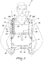
- the reference numerals 1, 100 designate a harness, particularly for supporting portable equipment 2.
- the harness 1, 100 comprises one or more bands 3 that wrap around the trunk or upper body or torso 4 of the user 5.
- the particular embodiments show, by way of nonlimiting example, a harness 1, 100 composed of a first band 3a that is Y-shaped so as to form a first wing 6a that is arranged to the rear of the trunk 4 so as to affect the back 7 of the user 5.
- the first wing 6a is advantageously arranged centrally along the back 7 of the user 5, substantially at the backbone.
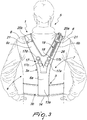
- the first band 3a is also constituted by a second wing and a third wing 6b, 6c, which wrap around the shoulders 8 of the user 5 and then descend substantially parallel to each other along his chest 9.
- the second wing and third wing 6b, 6c are optionally detachably connected transversely to each other by means of a strap 10 adapted to be arranged on the chest 9 of the user 5, substantially below the pectoral muscles 11, the connection occurring by means of a known first clip 12.
- the free ends 13a, 13b, 13c of the first wing 6a and of the second and third wings 6b, 6c are connected stably to a second band 3b, which wraps around the lumbar region 14 of the back 7 and of the waist of the user 5.
- the second band 3b is closed by means of a second clip 15, which is adapted to be arranged substantially at the abdomen 16 of the user 5.
- the end 13 a of the first wing 6a is connected directly and stably both to the end 13b of the second wing 6b and to the end 13c of the third wing 6c, so as to wrap around the serratus anterior of the trunk 4 and the serratus posterior inferior or the rhomboid major of the back 7.
- At least one coupling point 17 is obtained on the first wing 6a of the first band 3 a of the harness 1 for a first end 18 of at least one elastically deformable means 19, such as for example a cylindrical closed-coil helical extension spring, which passes above the shoulder 8 of the user 5;
- the harness 1 therefore, can comprise for example the possibility to mount two or more elastically deformable means 19 which are sized so as to support different weights of equipment 2.
- the number and placement of the coupling points 17 may vary depending on the specific requirements according to the weight of the equipment 2 to be supported and/or the weight and/or height of the user 5.
- the first end 18 of the elastically deformable means 19 is engaged with one of the coupling points 17a, 17b, 17c, 17d, depending on the specific requirements of the user 5.
- At least two guiding means 20a, 20b or 20c, 20d are obtained at least on one between the second or third wing 6b, 6c of the first band 3a of the harness 1 and are adapted to support and orient the elastically deformable means 19; a guiding means 20a or 20c is arranged on the rear part respectively of the second or third wing 6b or 6c, substantially at the height of the shoulder blade 21 of the user 5, while the other means 20b or 20d is arranged on the front part respectively of the second or third wing 6b or 6c, substantially at the height of the collarbone 22 of the user.
- the first end 18 of the elastically deformable means 19 is engaged in one of the two coupling points 17a, 17b that are oriented toward the second wing 6b and the elastically deformable means 19 is made to pass in the guiding means 20a, 20b arranged on the second wing 6b of the first band 3a of the harness 1, so as to wrap around the right shoulder 8 of the user 5; the choice between the coupling point 17a and the coupling point 17b is made according to the height and shoulder girth of the user 5 or according to the equipment 2 used.
- the first end 18 of the elastically deformable means 19 is engaged in one of the two coupling points 17c, 17d oriented toward the third wing 6c and the elastically deformable means 19 is made to pass in the guiding means 20c, 20d arranged on the third wing 6c of the first band 3a of the harness 1, so as to wrap around the left shoulder 8 of the user 5; the choice between the coupling point 17c and the coupling point 17d is made according to the height and shoulder girth of the user 5 or according to the equipment 2 used.
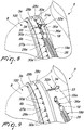
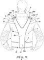
- At least one grip means 27a, 27b is stably associated on the second and third wings 6b, 6c of the first band 3a of the harness 100 and is connected to the second and third wings 6b, 6c by means of a plurality of connection means 28a, 28b, 28c, 28d, 28e, 28f, such as for example rivets or screws coupled to nuts.
- Each grip means 27a, 27b is constituted by a flat plate 29a, 29b, which has in plan view a substantially rectangular shape with rounded ends, is arranged at the shoulders 8 of the user 5 and is adapted to extend to the height of the chest 11 of the user 5 so as to assume an arc-like shape.
- Each plate 29a, 29b has, at the longitudinal central axis (or axis of symmetry), a plurality of holes or seats or openings or slots 30a, 30b which are longitudinal and have the same shape, preferably a rectangular one, have a chosen extension and are mutually spaced by the chosen extent.
- the number and placement of said plurality of holes or seats or openings or slots 30a, 30b can vary according to the specific requirements depending on the weight of the equipment 2 to be supported and/or the weight and/or height of the user 5.
- Each engagement means 31a, 31b comprises an elastic safety clip 32a, 32b, each clip having a straight lower arm 33 and a facing upper arm 34 which is contoured so that it can flex without being deformed.
- Each engagement means 31a, 31b also comprises a ring 35a, 35b which has an outside diameter that is substantially greater than the length of each one of said holes or seats or openings or slots 30a, 30b.
- An interconnection element 36a, 36b is associated with each ring 35a, 35b, each element being in turn associated with the first end 18 of an elastically deformable means 19a, 19b, such as for example a cylindrical helical closed-coil extension spring, each of which is adapted to be arranged along the chest 9 of the user 5.
- an elastically deformable means 19a, 19b such as for example a cylindrical helical closed-coil extension spring, each of which is adapted to be arranged along the chest 9 of the user 5.
- each elastically deformable means 19a, 19b directly with each ring 35a, 35b.
- each engagement means 31a, 31b provides that each ring 35a, 35b is arranged inside one of said plurality of holes or seats or openings or slots 30a, 30b arranged in the corresponding plate 35a, 35b, choosing the one most suitable for the specific requirement depending on the weight of the equipment 2 to be supported and/or the weight and/or height of the user 5 and/or the length of the springs 19a, 19b.
- Each ring 35a, 35b is then associated with the corresponding plate 29a, 29b by means of an elastic safety clip 32a, 32b, the lower arm 33 and upper arm 34 of which are interposed in a clamp-like arrangement between each one of the plates 35a, 35b and around which each ring 35a, 35b is arranged.
- Each elastically deformable means 19, 19a, 19b has a second end 23 which can be associated with the frame 24 of the equipment 2 by means of a connection element 25, such as for example a spring-clip.
- Each elastically deformable means 19, 19a, 19b is provided internally with a cable 26, preferably made of metallic material, such as for example steel, or other materials that have equivalent characteristics, such as for example nylon, which is stably associated with the first and second ends 18, 23.
- the cable 26 is longer than the elastically deformable means 19, 19a, 19b when it is not elongated and performs the task of not allowing the extension of the elastically deformable means 19, 19a, 19b beyond a given length depending on the weight of the equipment 2 or the height of the user or the type of terrain on which the work is to be performed, and this is done in order to avoid a mechanical stress.
- harness 1, 100 which is particularly usable to facilitate the use of portable equipment 2 regardless of the height of the user 5 or the dimensions or weight of said equipment 2 or the fact that the user 5 is right-handed or left-handed.
- the elastically deformable means 19 is then made to pass through the guiding means 20a, 20b arranged on the second wing 6b of the first band 3a of the harness 1, so as to wrap around the right shoulder 8 of the user 5; the user 5 then associates the second end 23 with the frame 24 of the mechanical equipment 2.
- the user 5 If the user 5 is left-handed, he chooses the most appropriate coupling point, depending on the weight of the equipment 2 that he must support and depending on his own height, between one of the two coupling points 17c, 17d, on which the first end 18 of the elastically deformable means 19 engages; the elastically deformable means 19 is then made to pass through the guiding means 20c, 20d arranged on the third wing 6c of the first band 3a of the harness 1, so as to wrap around the left shoulder 8 of the user 5; the user 5 then associates the second end 23 with the frame 24 of the mechanical equipment 2.
- the user 5 chooses the most appropriate coupling point, depending on the weight of the equipment 2 that he must support, depending on his height and on the length of the spring 19a, 19b, among one of said plurality of holes or seats or openings or slots 30a of the plate 35a and between one of said plurality of holes or seats or openings or slots 30b of the plate 35b, on each of which the corresponding engagement means 31a, 31b is engaged which is connected directly or indirectly to the first end 18 of each elastically deformable means 19a, 19b; the user 5 then associates the second ends 23 of each elastically deformable means 19a, 19b with the frame 24 of the mechanical equipment 2.
- the harness 1, 100 allows even prolonged use of the equipment 2 without the user being affected by pain in the arms, back or cervical vertebrae, respectively by virtue of the presence and the particular placement of the elastically deformable means 19 or of the elastically deformable means 19a, 19b, which allow on the one hand to absorb the vibrations that arrive from the equipment 2 and on the other hand allow the user 5 to support the weight of the equipment 2 in a manner that is distributed along multiple parts of the trunk 4, i.e., the back 7, the shoulders 8 and the chest 9.
- the elastically deformable means 19 in the harness 1 and the elastically deformable means 19a, 19b in the harness 100 allow complete and free maneuverability in space of the engaged equipment 2.
- the harness 1, 100 can be worn by the user easily and rapidly.
Landscapes
- Engineering & Computer Science (AREA)
- General Engineering & Computer Science (AREA)
- Mechanical Engineering (AREA)
- Life Sciences & Earth Sciences (AREA)
- Environmental Sciences (AREA)
- Professional, Industrial, Or Sporting Protective Garments (AREA)
- Insulating Bodies (AREA)
- Insertion, Bundling And Securing Of Wires For Electric Apparatuses (AREA)
Applications Claiming Priority (1)
| Application Number | Priority Date | Filing Date | Title |
|---|---|---|---|
| ITUB2015A006322A ITUB20156322A1 (it) | 2015-12-04 | 2015-12-04 | Imbragatura perfezionata, particolarmente per il supporto di attrezzature portatili. |
Publications (1)
| Publication Number | Publication Date |
|---|---|
| EP3175698A1 true EP3175698A1 (de) | 2017-06-07 |
Family
ID=55642579
Family Applications (1)
| Application Number | Title | Priority Date | Filing Date |
|---|---|---|---|
| EP16201617.4A Withdrawn EP3175698A1 (de) | 2015-12-04 | 2016-12-01 | Gurtzeug, insbesondere zum tragen einer tragbaren ausrüstung |
Country Status (2)
| Country | Link |
|---|---|
| EP (1) | EP3175698A1 (de) |
| IT (1) | ITUB20156322A1 (de) |
Cited By (1)
| Publication number | Priority date | Publication date | Assignee | Title |
|---|---|---|---|---|
| JP2021038574A (ja) * | 2019-09-03 | 2021-03-11 | 株式会社マキタ | 可搬式の作業機用のハーネス |
Citations (5)
| Publication number | Priority date | Publication date | Assignee | Title |
|---|---|---|---|---|
| US3317098A (en) * | 1965-10-26 | 1967-05-02 | Auraen Inge | Carrying device for a chain type motor saw |
| JP2005058064A (ja) * | 2003-08-11 | 2005-03-10 | Motome Karahashi | 吊支バンド |
| US20100006611A1 (en) * | 2008-07-11 | 2010-01-14 | Michael Knowles | Support apparatus |
| EP2240046A1 (de) * | 2008-02-07 | 2010-10-20 | Cifarelli S.p.A. | Stützvorrichtung für tragbare landwirtschaftsmaschinen, besonders für blas- und baumschüttelvorrichtungen und ähnliche maschinen |
| GB2501744A (en) * | 2012-05-03 | 2013-11-06 | Audiotel Internat Ltd | Weight distribution system for handheld sweep apparatus |
-
2015
- 2015-12-04 IT ITUB2015A006322A patent/ITUB20156322A1/it unknown
-
2016
- 2016-12-01 EP EP16201617.4A patent/EP3175698A1/de not_active Withdrawn
Patent Citations (5)
| Publication number | Priority date | Publication date | Assignee | Title |
|---|---|---|---|---|
| US3317098A (en) * | 1965-10-26 | 1967-05-02 | Auraen Inge | Carrying device for a chain type motor saw |
| JP2005058064A (ja) * | 2003-08-11 | 2005-03-10 | Motome Karahashi | 吊支バンド |
| EP2240046A1 (de) * | 2008-02-07 | 2010-10-20 | Cifarelli S.p.A. | Stützvorrichtung für tragbare landwirtschaftsmaschinen, besonders für blas- und baumschüttelvorrichtungen und ähnliche maschinen |
| US20100006611A1 (en) * | 2008-07-11 | 2010-01-14 | Michael Knowles | Support apparatus |
| GB2501744A (en) * | 2012-05-03 | 2013-11-06 | Audiotel Internat Ltd | Weight distribution system for handheld sweep apparatus |
Cited By (2)
| Publication number | Priority date | Publication date | Assignee | Title |
|---|---|---|---|---|
| JP2021038574A (ja) * | 2019-09-03 | 2021-03-11 | 株式会社マキタ | 可搬式の作業機用のハーネス |
| JP7307636B2 (ja) | 2019-09-03 | 2023-07-12 | 株式会社マキタ | 可搬式の作業機用のハーネス |
Also Published As
| Publication number | Publication date |
|---|---|
| ITUB20156322A1 (it) | 2017-06-04 |
Similar Documents
| Publication | Publication Date | Title |
|---|---|---|
| US4335875A (en) | Jogging rope harness | |
| US843478A (en) | Physical exerciser. | |
| US10259518B2 (en) | Garments having mechanisms integrated therein, gripping mechanisms, and methods of use thereof | |
| US10398923B2 (en) | Adjustable resistance band and system including same | |
| US20050113221A1 (en) | Tube connector for exercise device with elastic resistance | |
| US4676502A (en) | Variable weight support device | |
| US9205299B1 (en) | Power push up | |
| US1642911A (en) | Workman's saddle belt | |
| US20070015642A1 (en) | Body vest gym | |
| US3035747A (en) | Back pack | |
| US20130303346A1 (en) | Upper body toning device | |
| US4629183A (en) | Arm support device | |
| US20050113222A1 (en) | Resistive elastic tube assembly for exercise device | |
| US20070015640A1 (en) | Body vest gym | |
| EP3175698A1 (de) | Gurtzeug, insbesondere zum tragen einer tragbaren ausrüstung | |
| US3862709A (en) | Cable holder | |
| US1010796A (en) | Exercising apparatus. | |
| US11090526B2 (en) | Exercise device | |
| US2111963A (en) | Arm sling | |
| US10881901B2 (en) | Rehabilitation device and its use for exercising the shoulder region | |
| WO2018134478A1 (en) | Exercise equipment | |
| US20030134729A1 (en) | Variable resistance hand gripper device | |
| US20050113220A1 (en) | Exercise device with elastic resistance | |
| IT201900002775A1 (it) | Dispositivo per il sostegno di una attrezzatura manovrata manualmente da un operatore | |
| US20170056701A1 (en) | Exercise eqquipment |
Legal Events
| Date | Code | Title | Description |
|---|---|---|---|
| AK | Designated contracting states |
Kind code of ref document: A1 Designated state(s): AL AT BE BG CH CY CZ DE DK EE ES FI FR GB GR HR HU IE IS IT LI LT LU LV MC MK MT NL NO PL PT RO RS SE SI SK SM TR |
|
| AX | Request for extension of the european patent |
Extension state: BA ME |
|
| PUAI | Public reference made under article 153(3) epc to a published international application that has entered the european phase |
Free format text: ORIGINAL CODE: 0009012 |
|
| STAA | Information on the status of an ep patent application or granted ep patent |
Free format text: STATUS: THE APPLICATION IS DEEMED TO BE WITHDRAWN |
|
| 18D | Application deemed to be withdrawn |
Effective date: 20171208 |