EP3175512B1 - Connecteurs de câbles coaxiaux avec éléments de retenue de conducteurs - Google Patents
Connecteurs de câbles coaxiaux avec éléments de retenue de conducteurs Download PDFInfo
- Publication number
- EP3175512B1 EP3175512B1 EP15747349.7A EP15747349A EP3175512B1 EP 3175512 B1 EP3175512 B1 EP 3175512B1 EP 15747349 A EP15747349 A EP 15747349A EP 3175512 B1 EP3175512 B1 EP 3175512B1
- Authority
- EP
- European Patent Office
- Prior art keywords
- conductor
- connector
- retaining member
- insulator
- internal bore
- Prior art date
- Legal status (The legal status is an assumption and is not a legal conclusion. Google has not performed a legal analysis and makes no representation as to the accuracy of the status listed.)
- Active
Links
Images


Classifications
-
- H—ELECTRICITY
- H01—ELECTRIC ELEMENTS
- H01R—ELECTRICALLY-CONDUCTIVE CONNECTIONS; STRUCTURAL ASSOCIATIONS OF A PLURALITY OF MUTUALLY-INSULATED ELECTRICAL CONNECTING ELEMENTS; COUPLING DEVICES; CURRENT COLLECTORS
- H01R9/00—Structural associations of a plurality of mutually-insulated electrical connecting elements, e.g. terminal strips or terminal blocks; Terminals or binding posts mounted upon a base or in a case; Bases therefor
- H01R9/03—Connectors arranged to contact a plurality of the conductors of a multiconductor cable, e.g. tapping connections
- H01R9/05—Connectors arranged to contact a plurality of the conductors of a multiconductor cable, e.g. tapping connections for coaxial cables
- H01R9/053—Connectors arranged to contact a plurality of the conductors of a multiconductor cable, e.g. tapping connections for coaxial cables using contact members penetrating insulation
-
- H—ELECTRICITY
- H01—ELECTRIC ELEMENTS
- H01R—ELECTRICALLY-CONDUCTIVE CONNECTIONS; STRUCTURAL ASSOCIATIONS OF A PLURALITY OF MUTUALLY-INSULATED ELECTRICAL CONNECTING ELEMENTS; COUPLING DEVICES; CURRENT COLLECTORS
- H01R9/00—Structural associations of a plurality of mutually-insulated electrical connecting elements, e.g. terminal strips or terminal blocks; Terminals or binding posts mounted upon a base or in a case; Bases therefor
- H01R9/16—Fastening of connecting parts to base or case; Insulating connecting parts from base or case
- H01R9/18—Fastening by means of screw or nut
-
- H—ELECTRICITY
- H01—ELECTRIC ELEMENTS
- H01R—ELECTRICALLY-CONDUCTIVE CONNECTIONS; STRUCTURAL ASSOCIATIONS OF A PLURALITY OF MUTUALLY-INSULATED ELECTRICAL CONNECTING ELEMENTS; COUPLING DEVICES; CURRENT COLLECTORS
- H01R13/00—Details of coupling devices of the kinds covered by groups H01R12/70 or H01R24/00 - H01R33/00
- H01R13/58—Means for relieving strain on wire connection, e.g. cord grip, for avoiding loosening of connections between wires and terminals within a coupling device terminating a cable
- H01R13/5804—Means for relieving strain on wire connection, e.g. cord grip, for avoiding loosening of connections between wires and terminals within a coupling device terminating a cable comprising a separate cable clamping part
-
- H—ELECTRICITY
- H01—ELECTRIC ELEMENTS
- H01R—ELECTRICALLY-CONDUCTIVE CONNECTIONS; STRUCTURAL ASSOCIATIONS OF A PLURALITY OF MUTUALLY-INSULATED ELECTRICAL CONNECTING ELEMENTS; COUPLING DEVICES; CURRENT COLLECTORS
- H01R13/00—Details of coupling devices of the kinds covered by groups H01R12/70 or H01R24/00 - H01R33/00
- H01R13/648—Protective earth or shield arrangements on coupling devices, e.g. anti-static shielding
- H01R13/658—High frequency shielding arrangements, e.g. against EMI [Electro-Magnetic Interference] or EMP [Electro-Magnetic Pulse]
- H01R13/6591—Specific features or arrangements of connection of shield to conductive members
- H01R13/6592—Specific features or arrangements of connection of shield to conductive members the conductive member being a shielded cable
- H01R13/6593—Specific features or arrangements of connection of shield to conductive members the conductive member being a shielded cable the shield being composed of different pieces
Definitions
- the present disclosure relates generally to coaxial connectors and, more particularly, to coaxial connectors with conductor retaining members that require minimal coaxial cable preparation.
- Coaxial cable connectors such as F-connectors
- F-connectors are used to attach coaxial cables to another object such as an appliance or junction having a terminal adapted to engage the connector.
- F-connectors are often used to terminate a drop cable in a cable television system.
- the coaxial cable typically includes an inner conductor surrounded by a dielectric layer, which is in turn surrounded by a conductive grounding foil and/or braid defining a conductive grounding sheath.
- the conductive grounding sheath is itself surrounded by a protective outer jacket.
- the F-connector is typically secured over the prepared end of the jacketed coaxial cable, allowing the end of the coaxial cable to be connected with a terminal block, such as by a threaded connection with a threaded terminal of a terminal block.
- Crimp style F-connectors are connectors wherein a crimp sleeve is included as part of the connector body.
- a special radial crimping tool having jaws that form a hexagon, is used to radially crimp the crimp sleeve around the outer jacket of the coaxial cable to secure such a crimp style F-connector over the prepared end of the coaxial cable.
- Still another form of F-connector uses an annular compression sleeve to secure the F-connector over the prepared end of the cable.
- these F-connectors employ a plastic annular compression sleeve that is initially attached to the F-connector, but which is detached therefrom prior to installation of the F-connector.
- the compression sleeve includes an inner bore for following such compression sleeve to be passed over the end of the coaxial cable prior to installation of the F-connector.
- the end of the coaxial cable must be prepared by removing a portion of the outer braid and/or folding the outer braid back over the cable jacket. The F-connector itself is then inserted over the prepared end of the coaxial cable.
- the difficult step of flaring and folding the outer braid over the outer jacket is a time consuming and difficult process. Further, small fragments of the outer braid may break off. These small fragments may cause electrical shorts in nearby electrical systems and/or enter the skin of cable installer. Additionally, the necessity of tools to connect the connector to the cable is undesirable.
- US2009/0111323 discloses male and female N connectors with a deformable body attached to a metallic connector body mounted to a post.
- a dielectric guide is provided within the post, forming part of a contact assembly having diectric guide, contact and a spring clip. The guide may prevent backward movement of the contact assembly and a coaxial cable core after the contact assembly and cable core are moved fully forward within the connector during attachment of the coaxial cable to the connector.
- GB 2077 053 discloses an inner element for gripping the inner element of a coaxial cable.
- a coaxial cable connector according to claim 1.
- Embodiments of the present disclosure are directed to coaxial cable connectors that may be connected to a coaxial cable without the use of tools and without requiring that a braided outer connector layer be folded over an outer jacket layer of the coaxial cable. Only the inner connector of the coaxial cable is exposed during cable preparation. More specifically, upon insertion of a coaxial cable into the connector, a conductor retaining member contacts the inner conductor and retains the cable within the connector. Further, upon insertion of a coaxial cable into the connector, a protrusion member is interposed in an end-wise fashion between the braided outer conductor layer and the outer layer of the coaxial cable.
- a means for a continual ground path from the cable outer conductor grounding structure to the rotatable coupler of the connector is provided.
- a means for compressing the outer layer of the coaxial cable against the braided outer conductor layer and the protrusion member is also provided.
- Embodiments of the present disclosure are directed to coaxial cable connectors capable of being installed on a coaxial cable with limited preparation of the coaxial cable. More specifically, the coaxial cable connectors described herein do not require that the braided outer conductor layer of the coaxial cable be folded back over the outer jacket. Rather, only the inner conductor of the coaxial cable may be exposed at the stripped portion of the cable. Further, the installation of coaxial cable into the connector does not require the use of secondary compression or activation tools, although such tools may be used in some embodiments. As described in more detail below, a conductor retaining member contacts the inner conductor and prevents the coaxial cable connector from being pulled off of the coaxial cable. Various embodiments of connectors and coaxial cable assemblies are described in detail below.
- the example coaxial cable 1000 comprises an inner conductor 1010 surrounded by an insulator layer 1020.
- the insulator layer 1020 may also have a foil or other metallic covering 1030 in some embodiments.
- the coaxial cable 1000 further comprises a braided outer conductor layer 1040 which is covered and protected by an outer layer 1050 (i.e., a cable jacket).
- FIG. 1 further illustrates a stripped portion 1060 of the coaxial cable 1000 that results from a cable stripping process. Only the inner conductor 1010 of the coaxial cable 1000 is exposed in the stripped portion 1060 having a predetermined length. Because only the inner conductor 1010 is exposed, and the braided outer conductor layer 1040 does not need to be prepared by folding it back over the outer layer 1050, preparation of the coaxial cable 1000 is fast and efficient. Moreover, preparation of the coaxial cable 1000 in this manner eliminates many of the issues related to errant strands of the braided outer conductor layer 1040 that may be present when flaring and folding the braided outer conductor layer 1040.
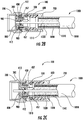
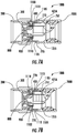
- the coaxial cable connector 100 generally comprises a rotatable coupling nut 200, an inner sleeve 300, a contact member 400, a body portion 700, an insulator member 800, and a conductor retaining member 900. As described in more detail below, embodiments may optionally include a pressure member 500 and a seal 600.
- the rotatable coupling nut 200 has a front end 210, a rear end 215, and an opening 230 extending there between.
- the opening 230 of the rotatable coupling nut 200 has an internal surface 235 that includes a threaded portion 240 for engaging a corresponding threaded portion of a mated connector.
- the rotatable coupling nut 200 further includes an inwardly projecting ring 255 to engage a rearward facing annular surface 335 of the inner sleeve 300.
- the rotatable coupling nut 200 may be made from any electrically conductive material.
- the rotatable coupling nut is made from a metallic material, such as brass, and is plated with a conductive, corrosion-resistant material, such as nickel.
- the inner sleeve 300 has a front end 310 and a rear end 315. Extending between the front end 310 and the rear end 315 is an internal surface 330. A rearward facing annular surface 335 serves to rotatably retain the rotatable coupling nut 200.
- the contact member 400 has a front end 410 and a rear end 415. Extending between the front end 410 and the rear end 415 is an internal surface 430.
- the contact member 400 further comprises a bore 451, a plurality of contacting members 412 extending outwardly at the front end 410, and at least one protruding member 457 protruding from the rear end 415.
- the contact member 400 electrically couples the rotatable coupling nut 200 to the braided outer conductor layer 1040 of the coaxial cable 1000 through the protruding members 457 and the contacting members 412.
- the protruding members 457 pierce the braided outer conductor layer 1040 of the coaxial cable 1000 and the contacting members 412 are flared outwardly such that they contact an inner surface of the rotatable coupling nut 200.
- an outer surface 340 of the inner sleeve 300 engages the contact member 400 by a press fit. It should be understood that other coupling methods may also be utilized.
- the contact member 400 may be made from any electrically conductive material.
- the contact member 400 may be made from a metallic material, such as brass, and plated with a conductive, corrosion-resistant material, such as tin.
- the contact member 400 may be made from any appropriate material.
- the pressure member 500 (also referred to herein as a "compression member”) is an optional component comprising various forms as will be shown in alternate embodiments herein.
- the pressure member 500 is a component that is configured to apply pressure to the outer layer 1050 of the coaxial cable 1000 to enhance electrical connection between the protruding members 457 of the contact member 400 and the braided outer conductor layer 1040 of the coaxial cable 1000.
- the pressure member 500 is in the form of an o-ring having an outside diameter 510, an inside diameter 515 and a cross sectional diameter 520.
- the pressure member 500 may be made from any compressible, rubber-like material such as ethylene propylene diene monomer (EPDM). It should be understood that the pressure member 500 may be made from any other appropriate material.
- EPDM ethylene propylene diene monomer
- An optional seal 600 has a front end 610 and a rear end 615. Extending between the front end 610 and the rear end 615 is an internal surface 630.
- the seal 600 further comprises an outer diameter 635, an outer relief 640, and tapered portions 645.
- the seal 600 may made from a rubber-like material, such as silicone, but may be made from any appropriate material.
- the body portion 700 has an internal surface 715 that extends between the front end 710 and the rear end 750 and defines a longitudinal opening 725.
- the body portion 700 also has an inner surface 720 to engage the contact member 400, and a recess 728. As shown in FIG. 3A , the seal 600 is disposed within the recess 728 and is operable to prevent liquids and debris from entering the connector 100.
- the body portion 700 may be made from plastic, such as acetal, but may be made from any appropriate material such as brass that is plated with a conductive, corrosion-resistant material, such as nickel.
- the insulator member 800 has a front end 810 and a rear end 815. Extending between the front end 810 and the rear end 815 is an internal surface 830.
- the insulator member 800 further comprises an inner diameter 835, an outer diameter 840, and an internal bore 845.
- the internal bore 845 may have a tapered portion to assist in guiding the inner conductor 1010 of the coaxial cable 1000 into the conductor retaining member 900.
- the insulator member 800 maintains the conductor retaining member 900.
- the insulator member 800 may be made as a multi-part construction in a clam-shell type configuration (see FIGS. 12A-12F ). Alternatively, the insulator member 800 may be molded about conductor retaining member 900 by insert molding.
- the conductor retaining member 900 is integral with insulator member 800 or the conductor retaining member 900 is disposed within the connector 100 by other means.
- the insulator member 800 may be made from plastic, such as acetal, but may be made from any appropriate, non-electrically conductive material.
- the conductor retaining member 900 has an aperture 930 between a front surface 910 and a rear surface 915.
- the conductor retaining member 900 may take on any form such that it is capable of allowing movement of the inner conductor 1010 through the aperture 930 in an insertion direction indicated by arrow A (i.e., a first direction), and prevent or resist movement of the inner conductor 1010 through the aperture 930 in a second, opposite direction from the insertion direction.
- conductor retaining member 900 may be made in a number of configurations designed to retain the inner conductor 1010 and engage the insulator member 800. It is noted that example conductor retaining member 900 configurations are depicted in FIGS. 8A-11B and are described in detail below.
- the conductor retaining member 900 may be made from a metallic material, such as stainless steel, phosphor bronze, or beryllium copper, and may be plated with a corrosion-resistant material, such as tin or nickel. Alternatively, the conductor retaining member 900 is made from a rigid plastic or any other appropriate material.
- the o-ring 550 is an optional component that is disposed between the rotatable coupling nut 200 and the body portion 700.
- the o-ring 550 may be provided to prevent environmental items such as moisture and dirt from entering the connector 100.
- the o-ring 550 may be made from a pliable rubber-like material such as ethylene propylene diene monomer (EPDM). However, the o-ring 550 may be made from any appropriate material.
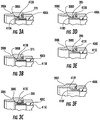
- a prepared coaxial cable 1000 (e.g., as shown in FIG. 1 ) is partially inserted through the longitudinal opening 725 of the body portion 700.
- the inner conductor 1010 is guided by the tapered portion of the insulator member 800 such that it approaches the aperture 930 of the conductor retaining member 900.
- the act of cable insertion is improved by not having the braided outer conductor layer 1040 exposed and folded back over the outer layer 1050.
- the amount of clearance between the coaxial cable 1000 and the connector 100 components allow the coaxial cable 1000 to easily enter the connector 100.
- the inner conductor 1010 is pushed through the aperture 930 of the conductor retaining member 900, sliding past flexible protrusions 940 (or fingers) defined by radial openings of the conductor retaining member 900, causing the protrusions 940 to flex in a direction towards the connector interface 105 in one embodiment (see FIGS. 8A-8F for example conductor retaining member configurations).
- the inner conductor 1010 engages the protrusions 940, it cannot be retracted in a direction opposite from the insertion direction without inverting the protrusions 940 to the reverse side of their original starting position, which requires a high degree of force.
- the inner conductor 1010 is directionally captured to achieve cable retention within the connector 100.
- the retaining force of the conductor retaining member 900 upon the copper clad steel inner conductor 1010 is high such that it prevents the connector 100 from being pulled off of the coaxial cable 1000. Insertion of the coaxial cable 1000 into the connector 100 may be accomplished completely by hand without the need for a secondary compression tool. However, such secondary compression tools may be utilized in some embodiments and depending on the particular style of the connector 100.
- FIG. 2C is a partial cross sectional view of the connector 100 of FIG 2A wherein the coaxial cable 1000 is further partially inserted into the connector 100.
- the inner conductor 1010 is advanced to protrude beyond the front end 810 of the insulator member 800 while the outer layer 1050 of the coaxial cable 1000 enters the seal 600.
- the outer relief 640 of the seal 600 gives way to allow the coaxial cable 1000 to more easily enter the connector 100.
- the circumferentially arranged protruding members 457 of the contact member 400 are positioned to coaxially align with the face of the braided outer conductor layer 1040.
- FIG. 2D is a partial cross sectional view of the connector 100 of FIG 2A wherein the coaxial cable 1000 is fully inserted into the connector 100.
- the inner conductor 1010 is advanced to protrude beyond the front end 210 of the rotatable coupling nut 200.
- the protruding members 457 pierce the front face of the braided outer conductor layer 1040 such that they are interposed between the outer layer 1050 and the braided outer conductor layer 1040. Alternatively, or coincidently, the protruding members 457 may be interposed between the metallic covering 1030, the braided outer conductor layer 1040 and the outer layer 1050.
- the protruding members 457, the contacting members 412 and the body of the contact member 400 provide a transfer of the ground path from the braided outer conductor layer 1040 of the coaxial cable to the rotatable coupling nut 200 of the connector 100.
- the ground path is provided through the protruding members 457 and the contact member 400, and may be transferred to the rotatable coupling nut 200 by rotational contact between the contacting members 412 of the contact member 400 and the rotatable coupling nut 200.
- Pressure member 500 may be utilized to provide additional inward circumferential force to create pressure against the outer layer 1050 and translate the pressure against the braided outer conductor layer 1040 and the protruding members 457.
- FIGS. 3A-3F various contact member configurations are schematically illustrated.
- the contact between the contact member, the inner sleeve, and the rotatable coupling nut provides a ground path between the braided outer conductor layer of the coaxial cable and the rotatable coupling nut.
- embodiments of the present disclosure are not limited to the example contact members 400A-400F depicted in FIGS. 3A-3F , and that other configurations are also possible.
- FIG. 3A depicts an embodiment wherein the contacting members 412A extend away from a body of the contact member 400A and away from the front end 410A.
- the contacting members 412A (tabs in this embodiment, or in other embodiments, a single annular contacting member surface) contact an annular interior ring 270 of the rotatable coupling nut 200A and a surface of the inner sleeve 300A.
- FIG. 3B depicts an embodiment wherein the contacting members 412B extend away from a body of the contact member 400B and toward the rear end 415B.
- the contacting members 412B (or in some embodiments, a single annular contacting member surface) contact an annular interior ring 275 of the rotatable coupling nut 200B and a surface of the inner sleeve 300B.
- FIG. 3C depicts another embodiment wherein the contacting members 412C extend away from a body of the contact member 400C and canted toward the rear end 415C.
- the contacting members 412C (or in some embodiments, a single annular contacting member surface) contact an annular interior ring 280 of the rotatable coupling nut 200C and a surface of the inner sleeve 300C.
- FIG. 3D depicts another embodiment wherein the contacting members 412D extend away from a body of the contact member 400D and canted away from the front end 410D.
- the contacting members 412D (or in some embodiments, a single annular contacting member surface) contact an annular interior ring 285 of the rotatable coupling nut 200D and a surface of the inner sleeve 300D.
- FIG. 3E depicts an embodiment wherein the contacting members 412E extend away from a body of the contact member 400E and toward the rear end 415E.
- the contacting members 412E (or in some embodiments, a single annular contacting member surface) contact an annular interior ring 290 of the rotatable coupling nut 200E and a surface of the inner sleeve 300E.
- FIG. 3F depicts an embodiment with planar contacting members 412F are configured slotted segmented portion that are flared radially outwardly and contact an annular interior ring 295 of the rotatable coupling nut 200F.
- FIGS. 4A-4C are cross sectional views of alternate embodiments of a coaxial cable connector providing a means for a continual ground path between the contact member and the rotatable coupling nut.
- a front end 410 portion of the contact member 400 e.g., either individual contacting members or a continuous contacting surface
- the inner sleeve 300' comprises one or more continuity features 312' that are radially flared outward and contact an inner annular ring of the rotatable coupling nut 200'.
- a front end 410 portion of the contact member 400 (e.g., either individual contacting members or a continuous contacting surface) is disposed between the insulator member 800" and a surface of the electrically conductive body portion 700".
- the body portion 700" comprises one or more continuity features 712" that are radially flared outward and contact an annular ring of the rotatable coupling nut 200". In this manner, a continual ground path is provided between the braided outer conductor layer 1040 of the coaxial cable 1000 and the rotatable coupling nut 200" through the protruding members 457, the body portion 700" and the continuity feature(s) 712".
- a front end 410 portion of the contact member 400 (e.g., either individual contacting members or a continuous contacting surface) is disposed between the insulator member 800'" and a surface of the electrically conductive body portion 700"'.
- the rotatable coupling nut 200'" comprises one or more continuity features 212"' that are radially flared inward and contact a surface of the body portion 700"'. In this manner, a continual ground path is provided between the braided outer conductor layer 1040 of the coaxial cable 1000 and the rotatable coupling nut 200"' through the protruding members 457, the body portion 700'" and the continuity feature(s) 212'".
- FIGS. 4A-4C schematically illustrate an alternative pressure member 500' having a slotted arrangement for surrounding the outer layer 1050.
- the alternative pressure member 500' is an alternative to the o-ring-type pressure member 500 described above and depicted in FIG. 2A .
- the alternative pressure member 500' applies an inward force to the outer layer 1050 of the coaxial cable 1000 to ensure electrical contact between the braided outer conductor layer 1040 and the protruding members 457 of the contact member 400.
- FIGS. 4A-4C illustrate a seal retainer 120 disposed within the body portion 700'.
- the seal retainer 120 has a front end 121 and a rear end 125. Extending between the front end 121 and the rear end 125 is an internal surface 123.
- the seal retainer 1200 further comprises a tapered membrane 124.
- the seal retainer 1215 may be made from plastic, such as acetal, but may be made from any appropriate material.
- the seal retainer 1200 may be disposed within the body portion 700' by a snap fit to both facilitate assembly of the seal 600 into and retained within the body portion 700'.
- the tapered membrane 124 serves to protect the tapered portion 645 of the seal 600 from accidental damage caused by the coaxial cable 1000 upon insertion and is flexible enough to allow the coaxial cable 1000 to be passed through the internal surface 123.
- FIGS. 5A-5D are partial cross sectional views of embodiments of a coaxial cable connector 100 that provide a means for compressing the outer layer 1050 of the coaxial cable 1000 against the braided outer conductor layer 1040 and the protruding members 457' of the contact member 400'. More specifically, FIGS. 5A and 5B illustrate contact member 400' having integral outer fingers 425', 425" to serve in the place of, or in addition to, the pressure member 500 illustrated in FIG. 2A . The integral outer fingers 425', 425" apply inward pressure on the outer layer 1050 of the coaxial cable 1000.
- the integral outer fingers 425', 425" of FIGS. 5A and 5B are shown in two different geometric configurations illustrating that there are a number of possible shapes that may be employed.
- FIGS. 5C and 5D depict a slidable contact member 400" wherein a portion of the slidable contact member 400" is disposed within a channel 752 defined by the insulator member 800 and the inner sleeve 300.
- a ramp 751 is provided in an inner surface of the body portion 700.
- the integral outer fingers 425'" of the slidable contact member 400'" are in an open position when slidable contact member 400'" is a rearward position ( FIG. 5C ).
- FIG. 5E depicts a slidable contact member 400"" as shown in FIGS. 5C and 5D and further comprising snap-in lugs 401 suitable for retention within the inner sleeve 300.
- FIGS. 5F-5H are perspective views of alternate embodiments of contact members 400F-400H provided for illustrative purposes.
- FIG. 5F illustrates a contact member 400F having a body 414 without contacting members, and three protruding members 457.
- FIG. 5G illustrates a contact member 400G having a body 414 and a plurality of contacting members 412 extending from the body 414 at the front end 410 and three protruding members 457 extending from an inner circumference of the body 414 at the rear end 415.
- FIG. 5H illustrates a contact member 400H having a plurality of contacting members 412 extending from the body 414 at the front end 410 and three protruding members 457 extending from an inner circumference of the body 414 at the rear end 415.
- the example contact member 400H further includes a compression flange 411 from which three outer fingers 425 extend. The three outer fingers 425 are radially aligned with the three protruding members 457 in the illustrated example.
- FIGS. 6A and 6B depict an embodiment wherein the connector 100A comprises a body coupling member 1100 partially disposed between the inner sleeve 300 and the rotatable coupling nut 200.
- the body coupling member 1100 comprises a plurality of forward notches 1110 and a plurality of rear notches 1105.
- the connector 100A comprises a slidable body portion 700A having a plurality of detents 770.
- the detents 770 are disposed in the plurality of rear notches 1105 when the connector 100A is in an uncompressed or open position. Using a tool, the connector 100A may be closed by sliding the slidable body portion 700A forward such that the detents 770 are disposed in the plurality of forward notches 1110.
- FIGS. 7A and 7B depict a connector 100B similar to the connector 100A illustrated in FIGS. 6A and 6B , except that the slidable body portion 700B includes an tapered portion 761 configured to press the plurality of outer fingers 425A toward the plurality of protruding members 457 when the slidable body portion 700B is transitioned from an open position ( FIG. 7A ) to a closed position ( FIG. 7B ).
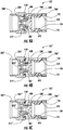
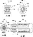
- FIGS. 8A-8F and 8A'-8F' schematically illustrate views of non-limiting conductor retaining members 900.
- FIGS. 8A-8F depict a front view of the example conductor retaining members 900
- FIGS. 8A'-8F' depict corresponding side view of the conductor retaining members 900 depicted in FIGS. 8A-8F .
- the example conductor retaining members 900 have a disk-like configuration.
- each of the example conductor retaining members 900 has a perimeter surface 905, a front surface 910 and a rear surface 915. Extending between the front surface 910 and the rear surface 915 is a central aperture sized to receive the inner conductor 1010 and a plurality of radial slots 935 that define a plurality of protrusions 940.
- the example conductor retaining member 900 of FIG. 8B and 8B' comprises canted portion 945 providing mechanical reinforcement against inner conductor 1010 withdrawal.
- FIGS. 8C and 8C' additionally include external slots 950 at the perimeter surface 905 to provide resistance against rotational movement within the insulator member.
- the conductor retaining member 900 of FIGS. 8D and 8D' comprises one or more engagmenet features, such as external protrusions 955, at the perimeter surface 905 to provide resistance against rotational movement within the insulator member.
- the conductor retaining member 900 of FIGS. 8E and 8E' comprises a slitted finger 960 at the perimeter surface 905 to provide resistance against rotational movement within the insulated member in the manner of a stamped thread configuration.
- the conductor retaining member 900 of FIGS. 8F and 8F' comprises canted external protrusions 970 at the perimeter surface 905 to provide resistance against rotational movement within the insulator member and mechanical reinforcement against flexing. It should be understood that the variations depicted in FIGS. 8A-8F and 8A'-8F' are for illustrative purposes, and that any combination of the illustrated features as well as those not illustrated may be utilized.
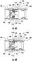
- FIG. 9A schematically illustrates in cross section an alternative conductor retaining member 1260 to the conductor retaining members 900 depicted in FIGS. 8A-8F and 8A'-8F' .
- the example conductor retaining member 1260 illustrated in FIG. 9A has a tube-like or cylindrical configuration.
- the conductor retaining member 1260 has a front end 1261 and a rear end 1262. Extending between the front end 1261 and the rear end 1262 is an aperture 1264.
- the conductor retaining member 1260 further comprises an outer surface 1263, a plurality of end tangs 1265, a plurality of radial tangs 1266, a plurality of slots 1267, and interior edge 1269.
- FIG. 9B is a cross sectional view of the conductor retaining member 1260 inserted into an internal surface 830 of the insulator member 800.
- the depth of insertion of conductor retaining member 1260 into the internal surface 830 of the insulator member 800 is limited by the end tangs 1265.
- the plurality of radial tangs 1266 embed into the internal surface 830 of insulator member 800, thereby preventing extraction of conductor retaining member 1260 from the internal surface.
- FIG. 9C is a partial cross sectional view of the insulator member 800 and the conductor retaining member 1260 as depicted in FIG. 9C with an inner conductor 1010 of a coaxial cable prior to insertion into the conductor retaining member 1260.
- FIG. 9D is a partial cross sectional view wherein the inner conductor 1010 is inserted into the aperture 1264 of the conductor retaining member 1260.
- the inner conductor 1010 radially expands the conductor retaining member 1260, thereby causing the plurality of radial tangs 1266 to further embed into the internal surface 830 of the insulator member 800.
- the interior edge 1269 of the radial tangs 1266 enter into the surface of the inner conductor 1010, thereby preventing the inner conductor 1010 from being moved axially rearward.
- FIGS. 10A-10D another alternative conductor retaining member 1280 is schematically illustrated.
- FIG. 10A depicts the conductor retaining member 1280 in cross section
- FIG. 10B is a schematic end view of the conductor retaining member 1280 depicted in FIG. 10A .
- the conductor retaining member 1280 has a bristle-type configuration.
- the conductor retaining member 1280 comprises an insulative portion 1281 that maintains retaining segments 1282 which fixture a plurality of radial bristle elements 1283.
- the plurality of bristle elements 1283 are arranged such that they form an aperture 1284.
- the insulative portion 1281 may be injection molded from a plastic material such as acetal or the like, for example. Retaining segments 1282 may likewise be constructed from a plastic material.
- the bristle elements 1283 may be made from a material such as a fine wire.
- FIG. 10C is a cross sectional illustration of the conductor retaining member 1280 depicted in FIGS. 10A and 10B with an inner conductor 1010 of a coaxial cable 1000 inserted therein. Insertion of the inner conductor 1010 into conductor retaining member 1280 causes the bristle elements 1283 to flex axially forward. Force applied to the coaxial cable 1000 to withdraw the inner conductor 1010 causes bristle elements 1283 to try to return to their original position. However, the diameter of the inner conductor 1010 prevents the aperture 1284 from returning to its original dimension, thereby forcing the bristle elements 1283 to be embedded into the surface of the inner conductor 1010. In this manner, the inner conductor 1010 is prevented from being removed from the conductor retaining member 1280.
- FIG. 10D is a cross sectional illustration of the conductor retaining member 1280 and coaxial cable 1000 of FIG. 10C taken along section line 10D-10D.
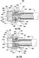
- FIGS. 11A and 11B illustrate a connector 100C having an alternative conductor retaining means.
- the connector 100C comprises a first insulator member 1500, a conductor retaining member 1550, and a second insulator member 1560.
- the first insulator member 1500 partially comprises a first coupling surface 1505, a first internal bore 1507, a plurality of fingers 1508, bumps 1509 and 1509', and a second internal bore 1510.
- the first insulator member 1500 is preferably made from an insulative material such as plastic and, as a non-limiting example, from acetal.
- the first internal bore 1507 extends from an insertion end 1501 of the first insulator member 1500 to the first coupling surface 1505.
- the first coupling surface 1505 is non-orthogonally transverse to a central axis of the first internal bore 1507 (i.e., it is sloped).
- the second internal bore 1510 extends from the first coupling surface 1505 to an exit surface 1503 of the first insulator member 1500.
- the outer surface of the first insulator member 1500 is at least partially disposed within the inner sleeve 300.
- the second insulator member 1560 partially comprises a base portion 1561, a protruding portion 1567, a second coupling surface 1562, a third internal bore 1563 through the base portion 1561 and the protruding portion 1567, a plurality of slots 1564, and a plurality of ridges 1565.
- the second insulator member 1560 may be made from an insulative material, such as plastic (e.g., acetal).
- the plurality of slots 1564 may include one or more inner circumferential slots 1564.
- the protruding portion 1567 of the second insulator member 1560 is slidably disposed within the first internal bore 1507 of the first insulator member 1570.
- the second coupling surface 1562 is non-orthogonally transverse to the central axis of the first internal bore 1507.
- the conductor retaining member 1550 comprises a central aperture 1555 and a face 1556.
- the conductor retaining member 1550 which may be configured as a circular disc, may be made from brass or other suitable material.
- the conductor retaining member 1550 is disposed within the first internal bore 1507 between the first coupling surface 1505 and the second coupling surface 1562 such that it is substantially orthogonal with respect to the central axis of the first internal bore 1507.
- a coaxial cable 1000 is partially inserted through the third internal bore 1563, the central aperture 1555 and the second internal bore 1510.
- the starting position of the conductor retaining member 1550 is maintained by bumps 1509 and 1509' which hold the face 1556 of conductor retaining member 1550 orthogonal to the central axis of the first internal bore 1507.
- FIG 11B is a cross sectional schematic illustration of the connector 110C shown in FIG. 11A wherein coaxial cable 1000 has been further advanced into the connector 100C.
- the insulator layer 1020 of the coaxial cable 1000 is forced against the base portion 1561 of second insulator member 1560, thereby driving the second insulator member 1560 into the conductor retaining member 1550.
- the sloped second coupling surface 1562 of the second insulator member 1560 causes the conductor retaining member 1550 to tilt off-axis and be driven past bump 1509' and against the sloped first coupling surface 1505 of the first insulator member 1500.
- the slots 1564 of the second insulator member 1560 slide in relation to the fingers 1508 of the first insulator member 1500 to maintain alignment of the components.
- the ridges 1565 engage the fingers 1508 by means of a snap fit, thereby retaining the second insulator 5160 at least partially within the first insulator member 1500.
- the tilting of the conductor retaining member 1550 causes the central aperture 1555 to engage the inner conductor 1010 of the coaxial cable 1000, thereby capturing coaxial cable 1000 within the connector 100C.
- FIG 12A is a cross sectional view of an insulator member 1600 which comprises a cap 1605, counter bore 1615, an annular lip 1617, a hinge 1620, a trepan 1625, a face 1628, a taper 1630, counter bore 1635, a main portion 1650, and a bore 1655.
- the insulator member 1600 is made from an insulative material (e.g., acetal).
- a representative embodiment of a conductor retaining member 900 is shown in preparation for installation into the insulator member 1600. In FIG.
- the conductor retaining member 900 is inserted into counter bore 1635 with the front surface 910 positioned against the face 1628 of the insulator member 1600.
- the cap 1605 is then closed by means of the hinge 1620 bringing the face 1610 against the rear surface 915 of the conductor retaining member 900 and engaging the annular lip 1617 with the trepan 1625, thereby fully encapsulating the conductor retaining member 900 within the insulator member 1600.
- the entire sub-assembly may now be assembled with the remaining connector components.
- FIG. 12C is a schematic view of an alternate embodiment of an insulator member 1700 which comprises a cap 1705, a main portion 1710, a hinge 1720, a recess 1735, a bore 1745, a pin 1746, and a hole 1747.
- the insulator member 1700 is made from an insulative material (e.g., acetal).
- FIG 12D illustrates the insulator member 1700 of FIG. 12C in a schematic end view wherein a representative version of a conductor retaining member 900 is shown at least partially inserted into the recess 1735 of the insulator member 1700.
- the cap 1705 is then closed by way of the hinge 1720, thereby fully encapsulating the conductor retaining member 900 within the insulator member 1700.
- the entire sub-assembly may now be assembled with the remaining connector components.
- FIG 12F is a cross sectional view of an insulator member 1800 which is at least partially comprised of two insulator halves 1805 and 1805', recesses 1835 and 1835, a plurality of holes 1847, and a plurality of pins 1846.
- the insulator member 1800 is preferably made from an insulative material such (e.g., acetal).
- a representative embodiment of a conductor retaining member 900 is shown in preparation for installation into the example insulator member 1800. The conductor retaining member 900 is inserted into the recess 1835.
- Half 1805 is then mated with half 1805' guided by a plurality of holes 1847, and a plurality of pins 1846 thus fully encapsulating conductor retaining member 900 within insulator halves 1805 and 1805'. Bore halves 1855 and 1855' mate to form an internal bore. The entire sub-assembly may now be assembled with the remaining connector components.
- the conductor retention means e.g., provided by the conductor retaining members described herein
- ground path means e.g., provided by the contact members described herein
- the conductor retaining members and contact members described herein may be incorporated into coaxial connectors sold by Corning Gilbert, Inc., such as those described in U.S. Pat. Nos. 5,975,951 , 5,997,350 , 7,018,235 , 7,182,639 and 7,331,820 .
Claims (15)
- Connecteur pour connecter un câble coaxial (1000) ayant un conducteur intérieur (1010) et une couche conductrice extérieure tressée (1040), le connecteur comprenant :une partie formant corps (700) comprenant une extrémité avant (710) et une extrémité arrière (750), la partie formant corps définissant un alésage (725) ;un élément de contact (400) comprenant une partie circonférentielle et au moins un élément en saillie (457), dans lequel :l'élément de contact (400) est conducteur de l'électricité ;une surface extérieure de la partie circonférentielle est au moins partiellement disposée à l'intérieur de l'alésage ; etle ou les éléments en saillie dépassent de la partie circonférentielle à l'intérieur de l'alésage (725) ;un manchon intérieur (300) disposé au moins partiellement à l'intérieur de la partie circonférentielle de l'élément de contact (400) ;un écrou d'accouplement pivotant (200) couplé de manière pivotante au manchon intérieur (300) ; etun élément de retenue du conducteur (900,1260,1280,1550) centré à l'intérieur du manchon intérieur (300), l'élément de retenue du conducteur étant configuré pour recevoir le conducteur intérieur (1010) du câble coaxial de telle sorte que le conducteur intérieur puisse passer librement à travers l'élément de retenue du conducteur (900,1260,1280,1550) dans une première direction vers l'extrémité avant de la partie formant corps, et ne puisse pas passer à travers l'élément de retenue du conducteur dans une deuxième direction s'éloignant de l'écrou d'accouplement pivotant ;caractérisé en ce que :l'écrou d'accouplement pivotant est conducteur de l'électricité et est couplé électriquement à l'élément de contact ;une surface extérieure de la partie circonférentielle de l'élément de contact (400) est au moins partiellement disposée à l'intérieur de l'alésage à l'extrémité avant (710) de la partie formant corps ;le ou les éléments en saillie dépassent de la partie circonférentielle à l'intérieur de l'alésage (725) vers l'extrémité arrière (750) de la partie formant corps ; etle contact entre l'élément de contact (400), le manchon intérieur (300) et l'écrou d'accouplement pivotant (200) est agencé pour fournir un chemin de masse entre la couche conductrice extérieure tressée (1040) et l'écrou d'accouplement rotatif (1010).
- Connecteur selon la revendication 1, dans lequel l'extrémité avant (710) de la partie formant corps, l'élément de contact (400), et le manchon intérieur (300) sont couplés ensemble par ajustement serré.
- Connecteur selon la revendication 1, dans lequel l'élément de retenue du conducteur (900,1260) comprend une ouverture centrale ayant un diamètre configuré pour recevoir le conducteur intérieur du câble coaxial, et une pluralité d'ouvertures radiales (935) qui définissent une pluralité de saillies flexibles (940,1266) qui permettent le déplacement du conducteur intérieur du câble coaxial dans la première direction et empêchent le déplacement du conducteur intérieur dans la deuxième direction.
- Connecteur selon la revendication 1, dans lequel l'élément de retenue du conducteur (1280) comprend une pluralité d'éléments en crins radiaux (1283) qui définissent une ouverture centrale, dans lequel la pluralité d'éléments en crins radiaux permettent le déplacement du conducteur intérieur du câble coaxial dans la première direction et empêchent le déplacement du conducteur intérieur dans la deuxième direction.
- Connecteur selon la revendication 1, comprenant en outre un élément isolant (800) comprenant une surface extérieure (840) et un alésage interne (845), dans lequel :au moins une partie de la surface extérieure (840) est en contact avec une surface intérieure du manchon intérieur (300) ; etl'élément de retenue du conducteur (900,1260,1280,1550) est disposé à l'intérieur de l'alésage interne de l'élément isolant.
- Connecteur selon la revendication 5, dans lequel l'alésage interne (845) de l'élément isolant comprend une partie conique de guidage du conducteur.
- Connecteur selon la revendication 5, dans lequel l'alésage interne (845) de l'élément isolant comprend une fente circonférentielle intérieure, et au moins une partie de l'élément de retenue du conducteur est disposée à l'intérieur de la fente circonférentielle intérieure.
- Connecteur selon la revendication 7, dans lequel l'élément de retenue du conducteur (900,1260,1280,1550) comprend en outre un ou plusieurs éléments d'engagement configurés pour empêcher le mouvement rotatif de l'élément de retenue du conducteur à l'intérieur de la fente.
- Connecteur selon la revendication 8, dans lequel le ou les éléments d'engagement comprennent au moins une encoche.
- Connecteur selon la revendication 5, dans lequel l'élément de retenue du conducteur (900,1260) comprend une ouverture centrale ayant un diamètre configuré pour recevoir le conducteur intérieur du câble coaxial, et une pluralité d'ouvertures radiales (935) qui définissent une pluralité de saillies flexibles qui permettent le déplacement du conducteur intérieur (1010) du câble coaxial dans la première direction et empêchent le déplacement du conducteur intérieur dans la deuxième direction.
- Connecteur selon la revendication 5, dans lequel :l'élément de retenue du conducteur (1260) est au moins partiellement disposé à l'intérieur de l'alésage interne,l'élément de retenue du conducteur comprend une pluralité de languettes d'extrémité (1265) qui sont en contact avec une surface interne de l'élément isolant, une pluralité de languettes radiales (1266) encastrées dans une surface de l'alésage interne, et une pluralité de fentes (1267) s'étendant sur une longueur de l'élément de retenue du conducteur.
- Connecteur selon la revendication 11, dans lequel la pluralité de languettes radiales (1266) est configurée pour se déplacer vers l'extérieur lors de l'insertion du conducteur intérieur (1010) du câble coaxial de telle sorte qu'une extrémité de chaque languette radiale (1266) s'engage avec le conducteur intérieur pour empêcher le déplacement du conducteur intérieur dans la deuxième direction.
- Connecteur selon la revendication 1, comprenant en outre :
un premier élément isolant (1500) comprenant une surface extérieure, un premier alésage interne (1507) et un deuxième alésage interne (1510), dans lequel :le premier alésage interne (1507) s'étend d'une extrémité d'insertion du premier élément isolant à une première surface d'accouplement (1505) qui est transversale non orthogonalement à un axe central du premier alésage interne ;le deuxième alésage interne (1510) s'étend de la première surface d'accouplement à une surface de sortie du premier élément isolant ; etla surface extérieure du premier élément isolant est au moins partiellement disposée à l'intérieur du manchon intérieur (300) ;un deuxième élément isolant (1560) comprenant une partie en saillie (1567) ayant une deuxième surface d'accouplement (1562), une partie de base (1561), et un troisième alésage interne (1563) à l'intérieur de la partie en saillie (1567) et de la partie de base (1561), dans lequel :la partie en saillie (1567) du deuxième élément isolant est disposée de manière coulissante à l'intérieur du premier alésage interne (1507) du premier élément isolant ; etla deuxième surface d'accouplement (1562) est transversale non orthogonalement à l'axe central du premier alésage interne (1507) ;la deuxième surface d'accouplement (1562) du deuxième élément isolant est décalée par rapport à la première surface d'accouplement (1505) du premier élément isolant ; dans lequel :l'élément de retenue du conducteur (1550) comprend une ouverture centrale (1550) ;l'élément de retenue du conducteur (1550) est disposé à l'intérieur du premier alésage interne (1507) entre la première surface d'accouplement et la deuxième surface d'accouplement de telle sorte qu'il est essentiellement orthogonal par rapport à l'axe central du premier alésage interne ; etlorsque le conducteur intérieur (1010) est inséré dans l'ouverture centrale (1550) et le premier alésage central (1507) du premier élément isolant, le câble coaxial translate le deuxième élément isolant (1560) de telle sorte que l'élément de retenue du conducteur (1550) devient transversal non orthogonalement au premier alésage interne du premier élément isolant et contacte à la fois la première surface d'accouplement (1505) et la deuxième surface d'accouplement (1562). - Connecteur selon la revendication 1, dans lequel le ou les éléments en saillie (457) sont configurés pour contacter une couche conductrice extérieure du câble coaxial inséré dans le connecteur.
- Connecteur selon la revendication 1, dans lequel le ou les éléments en saillie (457) comprennent une pluralité d'élément en saillie qui dépassent d'une circonférence de la partie circonférentielle.
Applications Claiming Priority (2)
| Application Number | Priority Date | Filing Date | Title |
|---|---|---|---|
| US201462030851P | 2014-07-30 | 2014-07-30 | |
| PCT/US2015/042771 WO2016019081A1 (fr) | 2014-07-30 | 2015-07-30 | Connecteurs de câbles coaxiaux avec éléments de retenue de conducteurs |
Publications (2)
| Publication Number | Publication Date |
|---|---|
| EP3175512A1 EP3175512A1 (fr) | 2017-06-07 |
| EP3175512B1 true EP3175512B1 (fr) | 2020-02-26 |
Family
ID=53783408
Family Applications (1)
| Application Number | Title | Priority Date | Filing Date |
|---|---|---|---|
| EP15747349.7A Active EP3175512B1 (fr) | 2014-07-30 | 2015-07-30 | Connecteurs de câbles coaxiaux avec éléments de retenue de conducteurs |
Country Status (8)
| Country | Link |
|---|---|
| US (1) | US9531090B2 (fr) |
| EP (1) | EP3175512B1 (fr) |
| CN (1) | CN106688145B (fr) |
| AU (1) | AU2015296508A1 (fr) |
| BR (1) | BR112017001928A2 (fr) |
| CA (1) | CA2956798A1 (fr) |
| DK (1) | DK3175512T3 (fr) |
| WO (1) | WO2016019081A1 (fr) |
Families Citing this family (7)
| Publication number | Priority date | Publication date | Assignee | Title |
|---|---|---|---|---|
| US10027040B2 (en) * | 2013-05-13 | 2018-07-17 | Perfectvision Manufacturing, Inc | Body clamp connector |
| US10367312B2 (en) | 2016-11-04 | 2019-07-30 | Corning Optical Communications Rf Llc | Connector for a coaxial cable |
| WO2018093767A1 (fr) * | 2016-11-15 | 2018-05-24 | Corning Optical Communications Rf Llc | Connecteur à tourner pour fermer, destiné à un câble coaxial. |
| MX2021000758A (es) * | 2018-07-17 | 2021-05-27 | Ppc Broadband Inc | Conector de cable coaxial. |
| CN111934122B (zh) * | 2019-04-24 | 2024-04-05 | 哈廷电子有限公司及两合公司 | 一种公连接器和母连接器及包括其的连接器组件 |
| EP3767750B1 (fr) * | 2019-07-16 | 2022-03-02 | Rosenberger Hochfrequenztechnik GmbH & Co. KG | Connecteur enfichable électrique, élément de protection isolant et procédé de montage d'un connecteur enfichable électrique |
| CN114221159B (zh) * | 2021-12-23 | 2023-08-29 | 杭州摩光通讯器材有限公司 | 一种空心电缆用的连接器 |
Family Cites Families (64)
| Publication number | Priority date | Publication date | Assignee | Title |
|---|---|---|---|---|
| US1822056A (en) | 1929-02-07 | 1931-09-08 | Gillette Vibber Company Inc | Threadless pipe connecter |
| US2805399A (en) | 1955-10-04 | 1957-09-03 | William W Leeper | Connector for uniting coaxial cables |
| US3058762A (en) | 1958-11-17 | 1962-10-16 | Earl E Howe | Screw thimble fitting having toggle rings with a sealing feature |
| FR1312525A (fr) * | 1961-11-07 | 1962-12-21 | Prise pour câble coaxial | |
| US3264602A (en) | 1964-03-13 | 1966-08-02 | Automatic Metal Products Corp | Electrical connectors for coaxial cables |
| US3571783A (en) | 1969-06-05 | 1971-03-23 | G & W Electric Speciality Co | Cable joining device for plastic and elastomeric insulated cables |
| US3710005A (en) | 1970-12-31 | 1973-01-09 | Mosley Electronics Inc | Electrical connector |
| US3744007A (en) | 1971-10-01 | 1973-07-03 | Vikoa Inc | Three-piece coaxial cable connector |
| US3874709A (en) | 1972-09-18 | 1975-04-01 | Cardinal Of Adrian | Tubing fitting |
| US3980325A (en) | 1973-04-12 | 1976-09-14 | Duane D. Robertson | Fitting for flexible plastic pipe |
| DE2343030C3 (de) | 1973-08-25 | 1980-11-06 | Felten & Guilleaume Carlswerke Ag, 5000 Koeln | AnschluBvorrichtung für Koaxialkabel |
| US3888522A (en) | 1974-04-01 | 1975-06-10 | Weatherhead Co | Flareless fitting |
| US4030741A (en) | 1975-01-20 | 1977-06-21 | Harvey Hubbell, Incorporated | Cord grips |
| US4146254A (en) | 1976-03-31 | 1979-03-27 | Bristol Products, Inc. | Coupler for tubing |
| US4062574A (en) | 1976-10-05 | 1977-12-13 | Scholin Industries, Inc. | Fitting assembly |
| US4133594A (en) * | 1977-06-07 | 1979-01-09 | Hi-G, Incorporated | Self-locking connector |
| US4243290A (en) | 1978-10-30 | 1981-01-06 | Williams Robert A | Shield termination means for electrical connector |
| US4342496A (en) * | 1980-05-22 | 1982-08-03 | Bunker Ramo Corporation | Contact assembly incorporating retaining means |
| CA1179029A (fr) | 1982-04-22 | 1984-12-04 | John B. Hutchison | Raccord etanche pour cables electriques |
| US4575274A (en) | 1983-03-02 | 1986-03-11 | Gilbert Engineering Company Inc. | Controlled torque connector assembly |
| US4583811A (en) | 1983-03-29 | 1986-04-22 | Raychem Corporation | Mechanical coupling assembly for a coaxial cable and method of using same |
| US4696532A (en) * | 1984-12-03 | 1987-09-29 | Raychem Corp. | Center conductor seizure |
| US4717355A (en) | 1986-10-24 | 1988-01-05 | Raychem Corp. | Coaxial connector moisture seal |
| US4739126A (en) | 1987-01-16 | 1988-04-19 | Amp Incorporated | Panel mount ground termination apparatus |
| DE3743636A1 (de) * | 1987-03-16 | 1989-07-13 | Kathrein Werke Kg | Anschlussvorrichtung fuer koaxialkabel |
| US4834675A (en) | 1988-10-13 | 1989-05-30 | Lrc Electronics, Inc. | Snap-n-seal coaxial connector |
| DE69022234T2 (de) | 1989-06-09 | 1996-06-13 | Raychem Corp | Durchführungsverbinder für koaxiale kabel. |
| US5207602A (en) | 1989-06-09 | 1993-05-04 | Raychem Corporation | Feedthrough coaxial cable connector |
| JPH073119Y2 (ja) | 1989-11-20 | 1995-01-30 | シーケーディ株式会社 | 管継手 |
| US5007861A (en) | 1990-06-01 | 1991-04-16 | Stirling Connectors Inc. | Crimpless coaxial cable connector with pull back cable engagement |
| US5066248A (en) | 1991-02-19 | 1991-11-19 | Lrc Electronics, Inc. | Manually installable coaxial cable connector |
| JPH08511376A (ja) | 1994-03-31 | 1996-11-26 | プリューフテヒニーク ディーター ブッシュ アクチェンゲゼルシャフト | 延長伝送装置に接続可能な接触端子に同軸ケーブルを接続するための装置 |
| US5529522A (en) | 1995-03-17 | 1996-06-25 | Huang; Chung-Chuan | Electrical connector |
| DE19615602A1 (de) | 1996-04-19 | 1997-10-23 | Lapp U I Gmbh & Co Kg | Kabelverschraubung |
| DE69734971T2 (de) | 1996-10-23 | 2006-06-22 | Thomas & Betts International Inc., Sparks | Koaxialkabelverbinder |
| GB9806642D0 (en) | 1998-03-27 | 1998-05-27 | Guest John D | Improvements in or relating to tube coupling |
| US5997350A (en) | 1998-06-08 | 1999-12-07 | Gilbert Engineering Co., Inc. | F-connector with deformable body and compression ring |
| US5975951A (en) | 1998-06-08 | 1999-11-02 | Gilbert Engineering Co., Inc. | F-connector with free-spinning nut and O-ring |
| US6705884B1 (en) | 1999-08-16 | 2004-03-16 | Centerpin Technology, Inc. | Electrical connector apparatus and method |
| US6298843B1 (en) | 2000-09-21 | 2001-10-09 | Robert M. Olsen | Outdoor cooking apparatus |
| US6648683B2 (en) | 2001-05-03 | 2003-11-18 | Timothy L. Youtsey | Quick connector for a coaxial cable |
| US20040031144A1 (en) | 2002-08-14 | 2004-02-19 | Michael Holland | Coaxial cable braid everting tool |
| US7048578B2 (en) | 2003-10-14 | 2006-05-23 | Thomas & Betts International, Inc. | Tooless coaxial connector |
| US6776657B1 (en) | 2003-11-13 | 2004-08-17 | Chen-Hung Hung | Connector capable of connecting to coaxial cable without using tool |
| US6955562B1 (en) * | 2004-06-15 | 2005-10-18 | Corning Gilbert Inc. | Coaxial connector with center conductor seizure |
| US7182639B2 (en) | 2004-12-14 | 2007-02-27 | Corning Gilbert Inc. | Coaxial cable connector |
| US7018235B1 (en) | 2004-12-14 | 2006-03-28 | Corning Gilbert Inc. | Coaxial cable connector |
| US7207839B1 (en) | 2005-07-12 | 2007-04-24 | Yazaki North America, Inc. | Wrap-around ferrule for coaxial cable connector |
| US7331820B2 (en) | 2005-09-19 | 2008-02-19 | Corning Gilbert Inc. | Chemically attached coaxial connector |
| US7288002B2 (en) | 2005-10-19 | 2007-10-30 | Thomas & Betts International, Inc. | Coaxial cable connector with self-gripping and self-sealing features |
| US7507907B2 (en) | 2006-09-22 | 2009-03-24 | Lapp Engineering & Co. | Cable feed-through |
| DK2220725T3 (en) * | 2007-10-31 | 2016-06-13 | Corning Gilbert Inc | Coaxial connector with telescopic centre manager mechanism |
| US7824214B2 (en) | 2008-06-30 | 2010-11-02 | Commscope, Inc. Of North Carolina | Coupling nut with cable jacket retention |
| US7635283B1 (en) * | 2008-11-24 | 2009-12-22 | Andrew Llc | Connector with retaining ring for coaxial cable and associated methods |
| US7806725B1 (en) | 2009-04-23 | 2010-10-05 | Ezconn Corporation | Tool-free coaxial connector |
| US8888526B2 (en) | 2010-08-10 | 2014-11-18 | Corning Gilbert, Inc. | Coaxial cable connector with radio frequency interference and grounding shield |
| US8075338B1 (en) | 2010-10-18 | 2011-12-13 | John Mezzalingua Associates, Inc. | Connector having a constant contact post |
| US8657626B2 (en) | 2010-12-02 | 2014-02-25 | Thomas & Betts International, Inc. | Cable connector with retaining element |
| DE102011003071A1 (de) | 2011-01-24 | 2012-07-26 | Lapp Engineering & Co. | Kabeldurchführung |
| DE202011103702U1 (de) * | 2011-07-26 | 2012-01-17 | Tyco Electronics Amp Italia S.R.L | Elektrischer Steckverbinder mit einem Kabelklemmabschnitt |
| US9407016B2 (en) | 2012-02-22 | 2016-08-02 | Corning Optical Communications Rf Llc | Coaxial cable connector with integral continuity contacting portion |
| US9287659B2 (en) | 2012-10-16 | 2016-03-15 | Corning Optical Communications Rf Llc | Coaxial cable connector with integral RFI protection |
| US10290958B2 (en) | 2013-04-29 | 2019-05-14 | Corning Optical Communications Rf Llc | Coaxial cable connector with integral RFI protection and biasing ring |
| EP3000154B1 (fr) | 2013-05-20 | 2019-05-01 | Corning Optical Communications RF LLC | Connecteur pour câble coaxial à protection rfi intégrée |
-
2015
- 2015-07-30 WO PCT/US2015/042771 patent/WO2016019081A1/fr active Application Filing
- 2015-07-30 CA CA2956798A patent/CA2956798A1/fr not_active Abandoned
- 2015-07-30 AU AU2015296508A patent/AU2015296508A1/en not_active Abandoned
- 2015-07-30 US US14/813,221 patent/US9531090B2/en active Active
- 2015-07-30 BR BR112017001928A patent/BR112017001928A2/pt not_active Application Discontinuation
- 2015-07-30 CN CN201580050451.9A patent/CN106688145B/zh not_active Expired - Fee Related
- 2015-07-30 EP EP15747349.7A patent/EP3175512B1/fr active Active
- 2015-07-30 DK DK15747349.7T patent/DK3175512T3/da active
Non-Patent Citations (1)
| Title |
|---|
| None * |
Also Published As
| Publication number | Publication date |
|---|---|
| WO2016019081A1 (fr) | 2016-02-04 |
| AU2015296508A1 (en) | 2017-02-16 |
| EP3175512A1 (fr) | 2017-06-07 |
| US20160036138A1 (en) | 2016-02-04 |
| CN106688145B (zh) | 2019-11-19 |
| US9531090B2 (en) | 2016-12-27 |
| CN106688145A (zh) | 2017-05-17 |
| DK3175512T3 (da) | 2020-03-23 |
| BR112017001928A2 (pt) | 2017-11-28 |
| CA2956798A1 (fr) | 2016-02-04 |
Similar Documents
| Publication | Publication Date | Title |
|---|---|---|
| EP3175512B1 (fr) | Connecteurs de câbles coaxiaux avec éléments de retenue de conducteurs | |
| JP4510770B2 (ja) | ケーブル把持部を備える同軸コネクタ | |
| RU2361338C2 (ru) | Опрессованный соединитель коаксиального кабеля (варианты) и способ его соединения с концом коаксиального кабеля | |
| EP3641061B1 (fr) | Ensemble de câble blindé | |
| CA2900731C (fr) | Connecteur a montage rapide pour un cable coaxial | |
| US3281756A (en) | Coaxial cable connector | |
| TWI591907B (zh) | 具有可壓縮套圈之同軸纜線連接器 | |
| EP3139446B1 (fr) | Connecteur de câble coaxial | |
| US8439707B2 (en) | Compression connector for multi-conductor cable | |
| US9882320B2 (en) | Coaxial cable connector | |
| CA2920842A1 (fr) | Connecteur de cable coaxial sans montant avec conducteur externe formable | |
| US10374368B2 (en) | Connector for a coaxial cable | |
| US10218132B2 (en) | Post-less, self-gripping connector for a coaxial cable | |
| EP3195420B1 (fr) | Ensemble câble et connecteur coaxiaux | |
| US10644417B2 (en) | Rotate-to-close connector for a coaxial cable | |
| KR102106208B1 (ko) | 차폐 케이블용 단자 조립체 | |
| EP3425741A1 (fr) | Ensemble de terminaison pour câble blindé | |
| US10680355B2 (en) | Terminal assembly for shielded cable | |
| WO2019103849A1 (fr) | Connecteur pour câble coaxial |
Legal Events
| Date | Code | Title | Description |
|---|---|---|---|
| STAA | Information on the status of an ep patent application or granted ep patent |
Free format text: STATUS: THE INTERNATIONAL PUBLICATION HAS BEEN MADE |
|
| 17P | Request for examination filed |
Effective date: 20170223 |
|
| AK | Designated contracting states |
Kind code of ref document: A1 Designated state(s): AL AT BE BG CH CY CZ DE DK EE ES FI FR GB GR HR HU IE IS IT LI LT LU LV MC MK MT NL NO PL PT RO RS SE SI SK SM TR |
|
| AX | Request for extension of the european patent |
Extension state: BA ME |
|
| PUAI | Public reference made under article 153(3) epc to a published international application that has entered the european phase |
Free format text: ORIGINAL CODE: 0009012 |
|
| STAA | Information on the status of an ep patent application or granted ep patent |
Free format text: STATUS: REQUEST FOR EXAMINATION WAS MADE |
|
| DAV | Request for validation of the european patent (deleted) | ||
| DAX | Request for extension of the european patent (deleted) | ||
| STAA | Information on the status of an ep patent application or granted ep patent |
Free format text: STATUS: EXAMINATION IS IN PROGRESS |
|
| 17Q | First examination report despatched |
Effective date: 20180308 |
|
| GRAP | Despatch of communication of intention to grant a patent |
Free format text: ORIGINAL CODE: EPIDOSNIGR1 |
|
| STAA | Information on the status of an ep patent application or granted ep patent |
Free format text: STATUS: GRANT OF PATENT IS INTENDED |
|
| INTG | Intention to grant announced |
Effective date: 20191010 |
|
| GRAS | Grant fee paid |
Free format text: ORIGINAL CODE: EPIDOSNIGR3 |
|
| GRAA | (expected) grant |
Free format text: ORIGINAL CODE: 0009210 |
|
| STAA | Information on the status of an ep patent application or granted ep patent |
Free format text: STATUS: THE PATENT HAS BEEN GRANTED |
|
| AK | Designated contracting states |
Kind code of ref document: B1 Designated state(s): AL AT BE BG CH CY CZ DE DK EE ES FI FR GB GR HR HU IE IS IT LI LT LU LV MC MK MT NL NO PL PT RO RS SE SI SK SM TR |
|
| REG | Reference to a national code |
Ref country code: GB Ref legal event code: FG4D |
|
| REG | Reference to a national code |
Ref country code: CH Ref legal event code: EP |
|
| REG | Reference to a national code |
Ref country code: AT Ref legal event code: REF Ref document number: 1238779 Country of ref document: AT Kind code of ref document: T Effective date: 20200315 |
|
| REG | Reference to a national code |
Ref country code: IE Ref legal event code: FG4D |
|
| REG | Reference to a national code |
Ref country code: DE Ref legal event code: R096 Ref document number: 602015047717 Country of ref document: DE |
|
| REG | Reference to a national code |
Ref country code: DK Ref legal event code: T3 Effective date: 20200317 |
|
| PG25 | Lapsed in a contracting state [announced via postgrant information from national office to epo] |
Ref country code: FI Free format text: LAPSE BECAUSE OF FAILURE TO SUBMIT A TRANSLATION OF THE DESCRIPTION OR TO PAY THE FEE WITHIN THE PRESCRIBED TIME-LIMIT Effective date: 20200226 Ref country code: RS Free format text: LAPSE BECAUSE OF FAILURE TO SUBMIT A TRANSLATION OF THE DESCRIPTION OR TO PAY THE FEE WITHIN THE PRESCRIBED TIME-LIMIT Effective date: 20200226 Ref country code: NO Free format text: LAPSE BECAUSE OF FAILURE TO SUBMIT A TRANSLATION OF THE DESCRIPTION OR TO PAY THE FEE WITHIN THE PRESCRIBED TIME-LIMIT Effective date: 20200526 |
|
| PGFP | Annual fee paid to national office [announced via postgrant information from national office to epo] |
Ref country code: DK Payment date: 20200625 Year of fee payment: 6 Ref country code: FR Payment date: 20200619 Year of fee payment: 6 |
|
| REG | Reference to a national code |
Ref country code: NL Ref legal event code: MP Effective date: 20200226 |
|
| REG | Reference to a national code |
Ref country code: LT Ref legal event code: MG4D |
|
| PG25 | Lapsed in a contracting state [announced via postgrant information from national office to epo] |
Ref country code: HR Free format text: LAPSE BECAUSE OF FAILURE TO SUBMIT A TRANSLATION OF THE DESCRIPTION OR TO PAY THE FEE WITHIN THE PRESCRIBED TIME-LIMIT Effective date: 20200226 Ref country code: BG Free format text: LAPSE BECAUSE OF FAILURE TO SUBMIT A TRANSLATION OF THE DESCRIPTION OR TO PAY THE FEE WITHIN THE PRESCRIBED TIME-LIMIT Effective date: 20200526 Ref country code: SE Free format text: LAPSE BECAUSE OF FAILURE TO SUBMIT A TRANSLATION OF THE DESCRIPTION OR TO PAY THE FEE WITHIN THE PRESCRIBED TIME-LIMIT Effective date: 20200226 Ref country code: GR Free format text: LAPSE BECAUSE OF FAILURE TO SUBMIT A TRANSLATION OF THE DESCRIPTION OR TO PAY THE FEE WITHIN THE PRESCRIBED TIME-LIMIT Effective date: 20200527 Ref country code: IS Free format text: LAPSE BECAUSE OF FAILURE TO SUBMIT A TRANSLATION OF THE DESCRIPTION OR TO PAY THE FEE WITHIN THE PRESCRIBED TIME-LIMIT Effective date: 20200626 Ref country code: LV Free format text: LAPSE BECAUSE OF FAILURE TO SUBMIT A TRANSLATION OF THE DESCRIPTION OR TO PAY THE FEE WITHIN THE PRESCRIBED TIME-LIMIT Effective date: 20200226 |
|
| PGFP | Annual fee paid to national office [announced via postgrant information from national office to epo] |
Ref country code: GB Payment date: 20200630 Year of fee payment: 6 |
|
| PG25 | Lapsed in a contracting state [announced via postgrant information from national office to epo] |
Ref country code: NL Free format text: LAPSE BECAUSE OF FAILURE TO SUBMIT A TRANSLATION OF THE DESCRIPTION OR TO PAY THE FEE WITHIN THE PRESCRIBED TIME-LIMIT Effective date: 20200226 |
|
| PG25 | Lapsed in a contracting state [announced via postgrant information from national office to epo] |
Ref country code: LT Free format text: LAPSE BECAUSE OF FAILURE TO SUBMIT A TRANSLATION OF THE DESCRIPTION OR TO PAY THE FEE WITHIN THE PRESCRIBED TIME-LIMIT Effective date: 20200226 Ref country code: EE Free format text: LAPSE BECAUSE OF FAILURE TO SUBMIT A TRANSLATION OF THE DESCRIPTION OR TO PAY THE FEE WITHIN THE PRESCRIBED TIME-LIMIT Effective date: 20200226 Ref country code: SM Free format text: LAPSE BECAUSE OF FAILURE TO SUBMIT A TRANSLATION OF THE DESCRIPTION OR TO PAY THE FEE WITHIN THE PRESCRIBED TIME-LIMIT Effective date: 20200226 Ref country code: CZ Free format text: LAPSE BECAUSE OF FAILURE TO SUBMIT A TRANSLATION OF THE DESCRIPTION OR TO PAY THE FEE WITHIN THE PRESCRIBED TIME-LIMIT Effective date: 20200226 Ref country code: RO Free format text: LAPSE BECAUSE OF FAILURE TO SUBMIT A TRANSLATION OF THE DESCRIPTION OR TO PAY THE FEE WITHIN THE PRESCRIBED TIME-LIMIT Effective date: 20200226 Ref country code: SK Free format text: LAPSE BECAUSE OF FAILURE TO SUBMIT A TRANSLATION OF THE DESCRIPTION OR TO PAY THE FEE WITHIN THE PRESCRIBED TIME-LIMIT Effective date: 20200226 Ref country code: ES Free format text: LAPSE BECAUSE OF FAILURE TO SUBMIT A TRANSLATION OF THE DESCRIPTION OR TO PAY THE FEE WITHIN THE PRESCRIBED TIME-LIMIT Effective date: 20200226 Ref country code: PT Free format text: LAPSE BECAUSE OF FAILURE TO SUBMIT A TRANSLATION OF THE DESCRIPTION OR TO PAY THE FEE WITHIN THE PRESCRIBED TIME-LIMIT Effective date: 20200719 |
|
| PGFP | Annual fee paid to national office [announced via postgrant information from national office to epo] |
Ref country code: DE Payment date: 20200615 Year of fee payment: 6 |
|
| REG | Reference to a national code |
Ref country code: AT Ref legal event code: MK05 Ref document number: 1238779 Country of ref document: AT Kind code of ref document: T Effective date: 20200226 |
|
| REG | Reference to a national code |
Ref country code: DE Ref legal event code: R097 Ref document number: 602015047717 Country of ref document: DE |
|
| PLBE | No opposition filed within time limit |
Free format text: ORIGINAL CODE: 0009261 |
|
| STAA | Information on the status of an ep patent application or granted ep patent |
Free format text: STATUS: NO OPPOSITION FILED WITHIN TIME LIMIT |
|
| PG25 | Lapsed in a contracting state [announced via postgrant information from national office to epo] |
Ref country code: IT Free format text: LAPSE BECAUSE OF FAILURE TO SUBMIT A TRANSLATION OF THE DESCRIPTION OR TO PAY THE FEE WITHIN THE PRESCRIBED TIME-LIMIT Effective date: 20200226 Ref country code: AT Free format text: LAPSE BECAUSE OF FAILURE TO SUBMIT A TRANSLATION OF THE DESCRIPTION OR TO PAY THE FEE WITHIN THE PRESCRIBED TIME-LIMIT Effective date: 20200226 |
|
| 26N | No opposition filed |
Effective date: 20201127 |
|
| PG25 | Lapsed in a contracting state [announced via postgrant information from national office to epo] |
Ref country code: SI Free format text: LAPSE BECAUSE OF FAILURE TO SUBMIT A TRANSLATION OF THE DESCRIPTION OR TO PAY THE FEE WITHIN THE PRESCRIBED TIME-LIMIT Effective date: 20200226 Ref country code: MC Free format text: LAPSE BECAUSE OF FAILURE TO SUBMIT A TRANSLATION OF THE DESCRIPTION OR TO PAY THE FEE WITHIN THE PRESCRIBED TIME-LIMIT Effective date: 20200226 Ref country code: PL Free format text: LAPSE BECAUSE OF FAILURE TO SUBMIT A TRANSLATION OF THE DESCRIPTION OR TO PAY THE FEE WITHIN THE PRESCRIBED TIME-LIMIT Effective date: 20200226 |
|
| REG | Reference to a national code |
Ref country code: CH Ref legal event code: PL |
|
| REG | Reference to a national code |
Ref country code: DE Ref legal event code: R082 Ref document number: 602015047717 Country of ref document: DE Representative=s name: HERNANDEZ, YORCK, DIPL.-ING., DE Ref country code: DE Ref legal event code: R081 Ref document number: 602015047717 Country of ref document: DE Owner name: CORNING OPTICAL COMMUNICATIONS APS, DK Free format text: FORMER OWNER: CORNING OPTICAL COMMUNICATIONS RF LLC, GLENDALE, ARIZ., US Ref country code: DE Ref legal event code: R081 Ref document number: 602015047717 Country of ref document: DE Owner name: AMPHENOL CABELCON APS, DK Free format text: FORMER OWNER: CORNING OPTICAL COMMUNICATIONS RF LLC, GLENDALE, ARIZ., US |
|
| REG | Reference to a national code |
Ref country code: BE Ref legal event code: MM Effective date: 20200731 |
|
| PG25 | Lapsed in a contracting state [announced via postgrant information from national office to epo] |
Ref country code: LU Free format text: LAPSE BECAUSE OF NON-PAYMENT OF DUE FEES Effective date: 20200730 Ref country code: LI Free format text: LAPSE BECAUSE OF NON-PAYMENT OF DUE FEES Effective date: 20200731 Ref country code: CH Free format text: LAPSE BECAUSE OF NON-PAYMENT OF DUE FEES Effective date: 20200731 |
|
| PG25 | Lapsed in a contracting state [announced via postgrant information from national office to epo] |
Ref country code: BE Free format text: LAPSE BECAUSE OF NON-PAYMENT OF DUE FEES Effective date: 20200731 |
|
| REG | Reference to a national code |
Ref country code: GB Ref legal event code: 732E Free format text: REGISTERED BETWEEN 20210603 AND 20210609 |
|
| REG | Reference to a national code |
Ref country code: DE Ref legal event code: R082 Ref document number: 602015047717 Country of ref document: DE Representative=s name: BECK & ROESSIG - EUROPEAN PATENT ATTORNEYS, DE Ref country code: DE Ref legal event code: R081 Ref document number: 602015047717 Country of ref document: DE Owner name: AMPHENOL CABELCON APS, DK Free format text: FORMER OWNER: CORNING OPTICAL COMMUNICATIONS APS, VORDINGBORG, DK |
|
| PG25 | Lapsed in a contracting state [announced via postgrant information from national office to epo] |
Ref country code: IE Free format text: LAPSE BECAUSE OF NON-PAYMENT OF DUE FEES Effective date: 20200730 |
|
| REG | Reference to a national code |
Ref country code: DE Ref legal event code: R119 Ref document number: 602015047717 Country of ref document: DE |
|
| REG | Reference to a national code |
Ref country code: DK Ref legal event code: EBP Effective date: 20210731 |
|
| GBPC | Gb: european patent ceased through non-payment of renewal fee |
Effective date: 20210730 |
|
| PG25 | Lapsed in a contracting state [announced via postgrant information from national office to epo] |
Ref country code: GB Free format text: LAPSE BECAUSE OF NON-PAYMENT OF DUE FEES Effective date: 20210730 Ref country code: DE Free format text: LAPSE BECAUSE OF NON-PAYMENT OF DUE FEES Effective date: 20220201 |
|
| PG25 | Lapsed in a contracting state [announced via postgrant information from national office to epo] |
Ref country code: TR Free format text: LAPSE BECAUSE OF FAILURE TO SUBMIT A TRANSLATION OF THE DESCRIPTION OR TO PAY THE FEE WITHIN THE PRESCRIBED TIME-LIMIT Effective date: 20200226 Ref country code: MT Free format text: LAPSE BECAUSE OF FAILURE TO SUBMIT A TRANSLATION OF THE DESCRIPTION OR TO PAY THE FEE WITHIN THE PRESCRIBED TIME-LIMIT Effective date: 20200226 Ref country code: FR Free format text: LAPSE BECAUSE OF NON-PAYMENT OF DUE FEES Effective date: 20210731 Ref country code: CY Free format text: LAPSE BECAUSE OF FAILURE TO SUBMIT A TRANSLATION OF THE DESCRIPTION OR TO PAY THE FEE WITHIN THE PRESCRIBED TIME-LIMIT Effective date: 20200226 |
|
| PG25 | Lapsed in a contracting state [announced via postgrant information from national office to epo] |
Ref country code: MK Free format text: LAPSE BECAUSE OF FAILURE TO SUBMIT A TRANSLATION OF THE DESCRIPTION OR TO PAY THE FEE WITHIN THE PRESCRIBED TIME-LIMIT Effective date: 20200226 Ref country code: AL Free format text: LAPSE BECAUSE OF FAILURE TO SUBMIT A TRANSLATION OF THE DESCRIPTION OR TO PAY THE FEE WITHIN THE PRESCRIBED TIME-LIMIT Effective date: 20200226 |
|
| PG25 | Lapsed in a contracting state [announced via postgrant information from national office to epo] |
Ref country code: DK Free format text: LAPSE BECAUSE OF NON-PAYMENT OF DUE FEES Effective date: 20210731 |