EP3175193B1 - Anlage zum trocknen und rösten von biomasse mit verbesserter energieeffizienz - Google Patents
Anlage zum trocknen und rösten von biomasse mit verbesserter energieeffizienz Download PDFInfo
- Publication number
- EP3175193B1 EP3175193B1 EP15744546.1A EP15744546A EP3175193B1 EP 3175193 B1 EP3175193 B1 EP 3175193B1 EP 15744546 A EP15744546 A EP 15744546A EP 3175193 B1 EP3175193 B1 EP 3175193B1
- Authority
- EP
- European Patent Office
- Prior art keywords
- heat
- burner
- drying
- roasting
- biomass
- Prior art date
- Legal status (The legal status is an assumption and is not a legal conclusion. Google has not performed a legal analysis and makes no representation as to the accuracy of the status listed.)
- Active
Links
- 238000001035 drying Methods 0.000 title claims description 98
- 239000002028 Biomass Substances 0.000 title claims description 79
- 239000007789 gas Substances 0.000 claims description 69
- 239000000567 combustion gas Substances 0.000 claims description 45
- 238000009434 installation Methods 0.000 claims description 43
- 238000002485 combustion reaction Methods 0.000 claims description 31
- XLYOFNOQVPJJNP-UHFFFAOYSA-N water Substances O XLYOFNOQVPJJNP-UHFFFAOYSA-N 0.000 claims description 26
- 229910001868 water Inorganic materials 0.000 claims description 20
- 230000003197 catalytic effect Effects 0.000 claims description 15
- 238000011084 recovery Methods 0.000 claims description 12
- 238000009833 condensation Methods 0.000 claims description 4
- 230000005494 condensation Effects 0.000 claims description 4
- 229920002678 cellulose Polymers 0.000 claims 1
- 239000001913 cellulose Substances 0.000 claims 1
- VNWKTOKETHGBQD-UHFFFAOYSA-N methane Chemical compound C VNWKTOKETHGBQD-UHFFFAOYSA-N 0.000 description 32
- 241000196324 Embryophyta Species 0.000 description 22
- QTBSBXVTEAMEQO-UHFFFAOYSA-N Acetic acid Chemical compound CC(O)=O QTBSBXVTEAMEQO-UHFFFAOYSA-N 0.000 description 19
- 239000000446 fuel Substances 0.000 description 18
- 239000003546 flue gas Substances 0.000 description 14
- 239000003345 natural gas Substances 0.000 description 14
- CURLTUGMZLYLDI-UHFFFAOYSA-N Carbon dioxide Chemical compound O=C=O CURLTUGMZLYLDI-UHFFFAOYSA-N 0.000 description 13
- UGFAIRIUMAVXCW-UHFFFAOYSA-N Carbon monoxide Chemical compound [O+]#[C-] UGFAIRIUMAVXCW-UHFFFAOYSA-N 0.000 description 13
- 238000002309 gasification Methods 0.000 description 11
- 238000000034 method Methods 0.000 description 11
- 230000008569 process Effects 0.000 description 10
- 239000000047 product Substances 0.000 description 10
- 238000001816 cooling Methods 0.000 description 9
- 239000002029 lignocellulosic biomass Substances 0.000 description 9
- IJGRMHOSHXDMSA-UHFFFAOYSA-N Atomic nitrogen Chemical compound N#N IJGRMHOSHXDMSA-UHFFFAOYSA-N 0.000 description 8
- 230000000052 comparative effect Effects 0.000 description 8
- 239000000203 mixture Substances 0.000 description 8
- 239000002023 wood Substances 0.000 description 8
- 238000006243 chemical reaction Methods 0.000 description 7
- 230000010354 integration Effects 0.000 description 7
- QVGXLLKOCUKJST-UHFFFAOYSA-N atomic oxygen Chemical compound [O] QVGXLLKOCUKJST-UHFFFAOYSA-N 0.000 description 6
- 238000010438 heat treatment Methods 0.000 description 6
- 239000007788 liquid Substances 0.000 description 6
- 239000001301 oxygen Substances 0.000 description 6
- 229910052760 oxygen Inorganic materials 0.000 description 6
- 239000001569 carbon dioxide Substances 0.000 description 5
- 229910002092 carbon dioxide Inorganic materials 0.000 description 5
- 230000003647 oxidation Effects 0.000 description 5
- 238000007254 oxidation reaction Methods 0.000 description 5
- 230000004907 flux Effects 0.000 description 4
- HYBBIBNJHNGZAN-UHFFFAOYSA-N furfural Chemical compound O=CC1=CC=CO1 HYBBIBNJHNGZAN-UHFFFAOYSA-N 0.000 description 4
- 239000000463 material Substances 0.000 description 4
- 238000003860 storage Methods 0.000 description 4
- OKTJSMMVPCPJKN-UHFFFAOYSA-N Carbon Chemical compound [C] OKTJSMMVPCPJKN-UHFFFAOYSA-N 0.000 description 3
- 230000015572 biosynthetic process Effects 0.000 description 3
- 229910052799 carbon Inorganic materials 0.000 description 3
- 238000004519 manufacturing process Methods 0.000 description 3
- 229910052757 nitrogen Inorganic materials 0.000 description 3
- 239000012265 solid product Substances 0.000 description 3
- 238000003786 synthesis reaction Methods 0.000 description 3
- 240000008042 Zea mays Species 0.000 description 2
- 239000002956 ash Substances 0.000 description 2
- 238000005265 energy consumption Methods 0.000 description 2
- 235000021183 entrée Nutrition 0.000 description 2
- 238000005469 granulation Methods 0.000 description 2
- 230000003179 granulation Effects 0.000 description 2
- 239000001257 hydrogen Substances 0.000 description 2
- 229910052739 hydrogen Inorganic materials 0.000 description 2
- 125000004435 hydrogen atom Chemical class [H]* 0.000 description 2
- 238000002347 injection Methods 0.000 description 2
- 239000007924 injection Substances 0.000 description 2
- 238000005453 pelletization Methods 0.000 description 2
- 238000004064 recycling Methods 0.000 description 2
- 238000000926 separation method Methods 0.000 description 2
- 238000011144 upstream manufacturing Methods 0.000 description 2
- IAYPIBMASNFSPL-UHFFFAOYSA-N Ethylene oxide Chemical compound C1CO1 IAYPIBMASNFSPL-UHFFFAOYSA-N 0.000 description 1
- 235000002918 Fraxinus excelsior Nutrition 0.000 description 1
- KPAMAAOTLJSEAR-UHFFFAOYSA-N [N].O=C=O Chemical compound [N].O=C=O KPAMAAOTLJSEAR-UHFFFAOYSA-N 0.000 description 1
- 239000012773 agricultural material Substances 0.000 description 1
- 239000002551 biofuel Substances 0.000 description 1
- 229910002091 carbon monoxide Inorganic materials 0.000 description 1
- 230000015556 catabolic process Effects 0.000 description 1
- 238000007084 catalytic combustion reaction Methods 0.000 description 1
- 239000003245 coal Substances 0.000 description 1
- 239000000498 cooling water Substances 0.000 description 1
- 238000007728 cost analysis Methods 0.000 description 1
- 238000006731 degradation reaction Methods 0.000 description 1
- 238000010790 dilution Methods 0.000 description 1
- 239000012895 dilution Substances 0.000 description 1
- 239000010791 domestic waste Substances 0.000 description 1
- -1 du formaldéhyde Chemical compound 0.000 description 1
- 230000007613 environmental effect Effects 0.000 description 1
- 238000001704 evaporation Methods 0.000 description 1
- 230000008020 evaporation Effects 0.000 description 1
- 238000000605 extraction Methods 0.000 description 1
- 239000000835 fiber Substances 0.000 description 1
- 239000012530 fluid Substances 0.000 description 1
- 239000002737 fuel gas Substances 0.000 description 1
- 239000008187 granular material Substances 0.000 description 1
- 238000000227 grinding Methods 0.000 description 1
- 239000011261 inert gas Substances 0.000 description 1
- 238000012432 intermediate storage Methods 0.000 description 1
- 230000007246 mechanism Effects 0.000 description 1
- VUZPPFZMUPKLLV-UHFFFAOYSA-N methane;hydrate Chemical compound C.O VUZPPFZMUPKLLV-UHFFFAOYSA-N 0.000 description 1
- WSFSSNUMVMOOMR-NJFSPNSNSA-N methanone Chemical compound O=[14CH2] WSFSSNUMVMOOMR-NJFSPNSNSA-N 0.000 description 1
- 238000000465 moulding Methods 0.000 description 1
- 239000005416 organic matter Substances 0.000 description 1
- 239000008188 pellet Substances 0.000 description 1
- 150000002989 phenols Chemical class 0.000 description 1
- 238000000197 pyrolysis Methods 0.000 description 1
- 239000007787 solid Substances 0.000 description 1
- 241000894007 species Species 0.000 description 1
- 239000010902 straw Substances 0.000 description 1
- 229920001864 tannin Polymers 0.000 description 1
- 239000001648 tannin Substances 0.000 description 1
- 235000018553 tannin Nutrition 0.000 description 1
- 239000011269 tar Substances 0.000 description 1
- 150000003505 terpenes Chemical class 0.000 description 1
- 235000007586 terpenes Nutrition 0.000 description 1
- 238000007669 thermal treatment Methods 0.000 description 1
Images


Classifications
-
- F—MECHANICAL ENGINEERING; LIGHTING; HEATING; WEAPONS; BLASTING
- F26—DRYING
- F26B—DRYING SOLID MATERIALS OR OBJECTS BY REMOVING LIQUID THEREFROM
- F26B23/00—Heating arrangements
- F26B23/02—Heating arrangements using combustion heating
- F26B23/022—Heating arrangements using combustion heating incinerating volatiles in the dryer exhaust gases, the produced hot gases being wholly, partly or not recycled into the drying enclosure
-
- C—CHEMISTRY; METALLURGY
- C10—PETROLEUM, GAS OR COKE INDUSTRIES; TECHNICAL GASES CONTAINING CARBON MONOXIDE; FUELS; LUBRICANTS; PEAT
- C10B—DESTRUCTIVE DISTILLATION OF CARBONACEOUS MATERIALS FOR PRODUCTION OF GAS, COKE, TAR, OR SIMILAR MATERIALS
- C10B49/00—Destructive distillation of solid carbonaceous materials by direct heating with heat-carrying agents including the partial combustion of the solid material to be treated
- C10B49/02—Destructive distillation of solid carbonaceous materials by direct heating with heat-carrying agents including the partial combustion of the solid material to be treated with hot gases or vapours, e.g. hot gases obtained by partial combustion of the charge
-
- C—CHEMISTRY; METALLURGY
- C10—PETROLEUM, GAS OR COKE INDUSTRIES; TECHNICAL GASES CONTAINING CARBON MONOXIDE; FUELS; LUBRICANTS; PEAT
- C10B—DESTRUCTIVE DISTILLATION OF CARBONACEOUS MATERIALS FOR PRODUCTION OF GAS, COKE, TAR, OR SIMILAR MATERIALS
- C10B53/00—Destructive distillation, specially adapted for particular solid raw materials or solid raw materials in special form
- C10B53/02—Destructive distillation, specially adapted for particular solid raw materials or solid raw materials in special form of cellulose-containing material
-
- C—CHEMISTRY; METALLURGY
- C10—PETROLEUM, GAS OR COKE INDUSTRIES; TECHNICAL GASES CONTAINING CARBON MONOXIDE; FUELS; LUBRICANTS; PEAT
- C10L—FUELS NOT OTHERWISE PROVIDED FOR; NATURAL GAS; SYNTHETIC NATURAL GAS OBTAINED BY PROCESSES NOT COVERED BY SUBCLASSES C10G, C10K; LIQUEFIED PETROLEUM GAS; ADDING MATERIALS TO FUELS OR FIRES TO REDUCE SMOKE OR UNDESIRABLE DEPOSITS OR TO FACILITATE SOOT REMOVAL; FIRELIGHTERS
- C10L9/00—Treating solid fuels to improve their combustion
- C10L9/08—Treating solid fuels to improve their combustion by heat treatments, e.g. calcining
- C10L9/083—Torrefaction
-
- F—MECHANICAL ENGINEERING; LIGHTING; HEATING; WEAPONS; BLASTING
- F26—DRYING
- F26B—DRYING SOLID MATERIALS OR OBJECTS BY REMOVING LIQUID THEREFROM
- F26B23/00—Heating arrangements
- F26B23/001—Heating arrangements using waste heat
- F26B23/002—Heating arrangements using waste heat recovered from dryer exhaust gases
- F26B23/004—Heating arrangements using waste heat recovered from dryer exhaust gases by compressing and condensing vapour in exhaust gases, i.e. using an open cycle heat pump system
-
- F—MECHANICAL ENGINEERING; LIGHTING; HEATING; WEAPONS; BLASTING
- F26—DRYING
- F26B—DRYING SOLID MATERIALS OR OBJECTS BY REMOVING LIQUID THEREFROM
- F26B2200/00—Drying processes and machines for solid materials characterised by the specific requirements of the drying good
- F26B2200/02—Biomass, e.g. waste vegetative matter, straw
-
- Y—GENERAL TAGGING OF NEW TECHNOLOGICAL DEVELOPMENTS; GENERAL TAGGING OF CROSS-SECTIONAL TECHNOLOGIES SPANNING OVER SEVERAL SECTIONS OF THE IPC; TECHNICAL SUBJECTS COVERED BY FORMER USPC CROSS-REFERENCE ART COLLECTIONS [XRACs] AND DIGESTS
- Y02—TECHNOLOGIES OR APPLICATIONS FOR MITIGATION OR ADAPTATION AGAINST CLIMATE CHANGE
- Y02B—CLIMATE CHANGE MITIGATION TECHNOLOGIES RELATED TO BUILDINGS, e.g. HOUSING, HOUSE APPLIANCES OR RELATED END-USER APPLICATIONS
- Y02B30/00—Energy efficient heating, ventilation or air conditioning [HVAC]
- Y02B30/52—Heat recovery pumps, i.e. heat pump based systems or units able to transfer the thermal energy from one area of the premises or part of the facilities to a different one, improving the overall efficiency
-
- Y—GENERAL TAGGING OF NEW TECHNOLOGICAL DEVELOPMENTS; GENERAL TAGGING OF CROSS-SECTIONAL TECHNOLOGIES SPANNING OVER SEVERAL SECTIONS OF THE IPC; TECHNICAL SUBJECTS COVERED BY FORMER USPC CROSS-REFERENCE ART COLLECTIONS [XRACs] AND DIGESTS
- Y02—TECHNOLOGIES OR APPLICATIONS FOR MITIGATION OR ADAPTATION AGAINST CLIMATE CHANGE
- Y02E—REDUCTION OF GREENHOUSE GAS [GHG] EMISSIONS, RELATED TO ENERGY GENERATION, TRANSMISSION OR DISTRIBUTION
- Y02E50/00—Technologies for the production of fuel of non-fossil origin
- Y02E50/10—Biofuels, e.g. bio-diesel
-
- Y—GENERAL TAGGING OF NEW TECHNOLOGICAL DEVELOPMENTS; GENERAL TAGGING OF CROSS-SECTIONAL TECHNOLOGIES SPANNING OVER SEVERAL SECTIONS OF THE IPC; TECHNICAL SUBJECTS COVERED BY FORMER USPC CROSS-REFERENCE ART COLLECTIONS [XRACs] AND DIGESTS
- Y02—TECHNOLOGIES OR APPLICATIONS FOR MITIGATION OR ADAPTATION AGAINST CLIMATE CHANGE
- Y02E—REDUCTION OF GREENHOUSE GAS [GHG] EMISSIONS, RELATED TO ENERGY GENERATION, TRANSMISSION OR DISTRIBUTION
- Y02E50/00—Technologies for the production of fuel of non-fossil origin
- Y02E50/30—Fuel from waste, e.g. synthetic alcohol or diesel
-
- Y—GENERAL TAGGING OF NEW TECHNOLOGICAL DEVELOPMENTS; GENERAL TAGGING OF CROSS-SECTIONAL TECHNOLOGIES SPANNING OVER SEVERAL SECTIONS OF THE IPC; TECHNICAL SUBJECTS COVERED BY FORMER USPC CROSS-REFERENCE ART COLLECTIONS [XRACs] AND DIGESTS
- Y02—TECHNOLOGIES OR APPLICATIONS FOR MITIGATION OR ADAPTATION AGAINST CLIMATE CHANGE
- Y02P—CLIMATE CHANGE MITIGATION TECHNOLOGIES IN THE PRODUCTION OR PROCESSING OF GOODS
- Y02P20/00—Technologies relating to chemical industry
- Y02P20/10—Process efficiency
- Y02P20/129—Energy recovery, e.g. by cogeneration, H2recovery or pressure recovery turbines
-
- Y—GENERAL TAGGING OF NEW TECHNOLOGICAL DEVELOPMENTS; GENERAL TAGGING OF CROSS-SECTIONAL TECHNOLOGIES SPANNING OVER SEVERAL SECTIONS OF THE IPC; TECHNICAL SUBJECTS COVERED BY FORMER USPC CROSS-REFERENCE ART COLLECTIONS [XRACs] AND DIGESTS
- Y02—TECHNOLOGIES OR APPLICATIONS FOR MITIGATION OR ADAPTATION AGAINST CLIMATE CHANGE
- Y02P—CLIMATE CHANGE MITIGATION TECHNOLOGIES IN THE PRODUCTION OR PROCESSING OF GOODS
- Y02P70/00—Climate change mitigation technologies in the production process for final industrial or consumer products
- Y02P70/10—Greenhouse gas [GHG] capture, material saving, heat recovery or other energy efficient measures, e.g. motor control, characterised by manufacturing processes, e.g. for rolling metal or metal working
Definitions
- the present invention relates to a plant for drying and roasting biomass, regardless of its type.
- the invention aims to reduce the energy cost of a combined plant for drying and roasting biomass, preferably lignocellulosic biomass.
- biomass in the context of the invention, any inhomogeneous material of plant or animal origin containing carbon, such as lignocellulosic biomass, forestry or agricultural residues (straw), which can be quasi -sec or soaked with water as household waste.
- the biomass may be of the lignocellulosic type, such as wood and agricultural materials and have any moisture content, preferably comprising between 10 and 60% of water, and be introduced into the installation according to the invention in all varied forms such as platelets, granules ...
- valorization of biomass is envisaged in order to diversify energy resources.
- the thermal conversion processes by gasification and combustion are particularly envisaged.
- the factories called "Biomass to Liquid”, designated by the acronym BtL are factories intended to implement a thermochemical conversion process of the biomass by gasification in order to produce a liquid fuel.
- BtL plants have already been widely described with a large number of economic data both in investment and production cost: [1], [2].
- the BtL plants more generally the factories designed to produce gaseous or liquid fuel from biomass, which are currently being designed are demonstration projects that aim to test and validate the entire technological chain of the thermochemical conversion process.
- the first stage of implementation or process in its own right consists in drying the wet biomass. In fact, the moisture of freshly collected biomass is typically between 30 and 50%, this initial rate of humidity varying according to the type of biomass, the collection period and the location where the biomass is stored.
- the roasting of the preferably lignocellulosic biomass is a step of pretreatment of the biomass with a view to injecting it in pulverized form into a driven-flow reactor (gasification reactor) or into a so-called biomass and coal co-combustion reactor. in a coal-fired power station or for granulation.
- the fibrous and elastic structure of the biomass renders its micronization energy-consuming and confers on the milled product characteristics that are unsuitable for an injection in pulverized form.
- Roasting is a gentle thermal treatment of biomass at the interface between drying and pyrolysis, usually carried out at temperatures between 200 and 300 ° C and aimed at removing water and modifying some of the organic matter biomass to break its fibers. In other words, this mild heat treatment alters the fibrous structure of the biomass, thereby facilitating its subsequent grinding and injection into a gasification or co-combustion reactor.
- Pretreatment by roasting also improves the properties of the biomass for storage by conferring in particular hydrophobicity and resistance to biological degradation.
- Granulation is also a possible application after roasting of the material.
- the products resulting from the roasting are the solid, the roasting gases and the condensables.
- Roasting reactors can be classified into two distinct categories depending on the direct heat-exchange heat-exchange mechanism in which the hot gases are in direct contact with the carbonaceous charge, or indirectly heated by which the heat transfer takes place. through an exchanger.
- roasting integrates the rationalization of heat in a limited way.
- the roasting gases can be burned to meet the emission requirements of the environment, using an additional fuel supply, natural gas in general.
- the resulting flue gas may nevertheless contain too much oxygen for use in direct contact with the biomass during roasting.
- the catalytic burner of this system receives the combustion gas after recirculation in the dryer and the unit of cooling, and in the roasting reactor.
- the fuel roasting products are therefore highly diluted in the burner, and a supply of the additional fuel burner is therefore necessary.
- it is intended to have cooling for the recirculation of the flue gas in the cooling unit.
- the patent application US20120137538 proposes a multi-stage reactor with separate drying and roasting zones.
- the gaseous roasting effluents are burned.
- the flue gas is used to indirectly heat the drying gas of the drying loop. It is then introduced into the roasting zone and recycled into the burner while being enriched by the released gases.
- the mixture of the flue gas with the gaseous effluents can be introduced into a condenser for water and the separation of the condensables, so that some of the roasting products with high heating values are condensed and therefore not valued in the burner .
- Additional fuel can be used in the burner to provide the necessary heat.
- the patent US8198493 proposes a system in which the biomass is dried in a rotating drum, preferably with a level of 2 to 4% residual moisture and then feeds an indirect heating rotary roasting reactor.
- the heat supplied to the roasting reactor and the drum dryer is by conventional burners that can use a portion of the dry biomass of the rotating drum as a fuel.
- the burner dedicated to the drum-dryer also uses the gaseous effluents produced in the rotary roasting reactor.
- the resulting flue gas is mixed with the flue gas used to indirectly heat the roasting reactor before entering the rotary dryer.
- the publication [6] provides for drying and roasting in a pellet production process that the roasting off-gases are recycled to the roasting reactor before being burned in an additional fuel burner.
- the flue gas produced in the burner is used to heat the torrefaction gas loop and to directly heat the biomass in the drying reactor.
- the publication FR2982274 A1 discloses a drying installation according to the preamble of claim 1.
- the state-of-the-art installations mentioned above certainly provide for using the gases released during roasting by conventional or catalytic combustion, but none of them systematically exploits the full potential of heat integration.
- the object of the invention is to respond at least in part to this need.
- the biomass may advantageously be lignocellulosic biomass.
- the invention reduces the energy cost of drying and roasting of biomass compared to techniques according to the state of the art because one increases the lower heating value (PCI) and reduces the consumption of natural gas.
- PCI lower heating value
- the temperature may be between 100 and 300 ° C, and more particularly between 100 and 200 ° C. Indeed, above 200 ° C the reactions that take place are not only drying reactions, and the risk increases to see the concentration of tars increase in the effluents produced in the reactor.
- the temperature is preferably between 200 and 300 ° C.
- the temperature is preferably still between 250 and 300 ° C for wood type biomass and between 220 and 280 ° C for agricultural type biomass. In fact, wood reacts to higher temperatures than agricultural biomasses.
- the outlet of the first burner is connected directly to the drying reactor by the supply line of the drying gas, the heat recovery element then being said supply line.
- the heat recovery element is a second heat exchanger, adapted to recover at least a portion of the heat available in the combustion gas recovery line from the first burner, and transfer it to the line drying gas supply.
- a third heat exchanger can be advantageously provided, adapted to recover at least a portion of the available heat in the line for recovering the combustion gas coming from the first burner, and transfer it to the combustion air. to preheat the latter before entering the first burner.
- the installation comprises a fourth heat exchanger, adapted to recover at least a portion of the heat still available in the combustion gas from the first burner, after transfers to the gas. drying and combustion gas, and transfer it to the biomass, before entering the drying reactor.
- the installation comprises a gas compressor adapted to compress the gas resulting from drying in order to recover the sensible heat of the water evaporated during the condensation drying.
- the outlet of the second burner is connected directly to the roasting reactor by the line for recovering the combustion gas from the second burner.
- the installation comprises a fifth heat exchanger, adapted to recover at least a portion of the heat available in the combustion gas from the second burner, and transfer it to the roasting gas to heat the latter before its entering the roasting reactor.
- the installation comprises a sixth heat exchanger, adapted to recover at least a portion of the heat still available in the combustion gas from the second burner, after transfer to the roasting gas, and transfer it to the drying gas before entering the drying reactor.
- the burners may be of conventional type, that is to say operating by air oxidation or catalytic type, that is to say according to an air oxidation process carried out by a catalytic material and which releases heat at a lower temperature than the combustion of a conventional burner.
- the first burner is a so-called conventional flame type burner.
- the second burner is a catalytic type burner.
- the plant according to the invention can be integrated in a thermochemical conversion plant of biomass into a synthesis gas widely known under the name Syngaz, by gasification in a gasification reactor in order to produce a fuel or a fuel, in particular a liquid fuel, or other synthetic product.
- the synthesis can be made according to the Fischer-Tropsch process to produce liquid diesel or another fuel.
- the plant according to the invention can also be integrated into a pelletizing installation of the roasted biomass.
- the installation according to the invention can also be integrated into a co-combustion installation.
- the invention also relates to the use of the plant described for the drying and roasting of lignocellulosic biomass.
- the same reference numerals do not necessarily designate the same elements of the installations according to the invention and according to the state of the art.
- the numerical references E1, E2 of the heat exchangers according to the state of the art do not designate the same heat exchangers E1, E2, the latter being used to perform other functions.
- the designated burner U4 in the plant according to the state of the art is the only burner dedicated to supply heat to the roasting reactor and the drying reactor, while the burner U4 in the plant according to the invention.
- the invention is the burner dedicated to bringing the heat mainly to the roasting reactor.
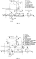
- Comparative Examples 1 and 2 of an installation according to the state of the art are represented in Figures 1 and 2 while Examples 3 to 5 relating to an installation according to the invention are represented in Figures 3 to 5 .
- Comparative Example 1 ( figure 1 ) and examples 3 and 5 ( figures 3 and 5 ) according to the invention relate to configurations of installation with direct heat exchange, because the heat required for roasting uses that directly of the combustion gas from a burner in direct contact with the biomass within the roasting reactor U2 .
- the roasting gases are diluted with the flue gases.
- the addition of a fuel, such as natural gas for example, may become necessary to obtain a gas mixture with an adiabatic combustion temperature sufficiently high to exploit the calorific value.
- Comparative Example 2 ( figure 2 ) and example 4 ( figure 4 ) according to the invention relate to installation configurations with indirect heat exchange, because the heat required for roasting uses a loop of roasting gas indirectly heated by combustion gases from a burner to provide the heat necessary for roasting in itself. Thus, in these indirect heat exchange configurations, the roasting gases are not diluted with the flue gases.
- Raw lignocellulosic biomass capable of being fed continuously from a suitable storage tank, not shown, feeds a reactor / dryer of biomass U1, connected downstream to a roasting reactor U2 itself connected downstream to a Cooling unit U3 adapted to cool the roasted biomass.
- compositions, relative flows and reference temperatures at the inlet and outlet of each of the reactors U1 and U2 and the cooling unit U3, that is to say at the points of the fluidic lines referenced 1, 2, 3 and 4, are given in Table 1 below, for all the examples both according to the state of the art and according to the invention.
- the drying and roasting plant represented in figure 1 is an installation according to the state of the art, without energy integration and which does not exploit the calorific value of the roasting gases.
- the heat required for the process is provided entirely by the natural gas burned in a conventional type burner.
- roasting gases are diluted directly in the combustion gases from the single conventional burner U4.
- a heat exchanger E1 which recovers the heat available from the roasting reactor U2 and transfers it to the drying gas to heat the latter before entering the drying reactor U1.
- the drying and roasting plant represented in figure 2 is an installation according to the state of the art, with energy integration by heat recovery with indirect heat exchange.
- the roasting gases are burned with natural gas to provide the necessary heat for the roasting gas loop.
- the heat exchange is indirect: thus, at the outlet of the single conventional burner U4, is arranged a heat exchanger E1 which recovers the available heat from the burner U4 and transfers it to the roasting gas to heat the latter before its entering the roasting reactor U2.
- the roasting gas is not diluted with the flue gas.
- Downstream of the exchanger E1 on the exhaust line of the combustion gas is arranged another heat exchanger E2 which recovers the heat still available and transfers it to the drying gas to heat the latter before entering the reactor. drying U1.
- the drying and roasting plant represented in figure 3 is an installation according to the invention, with energy integration and with a direct heat exchange.
- the installation comprises two separate burners, namely a conventional U4 burner dedicated to drying and a catalytic burner dedicated to U5 roasting.
- the combustion gas from the burner U4 is used to heat the air used to dry the biomass via the heat exchanger E3.
- the residual heat in the drying gas is used to preheat the combustion air of the burner U4 via another heat exchanger E2.
- the gas resulting from the drying can be compressed to allow the recovery of the sensible heat of the evaporated water during the condensation drying (variant not shown).
- downstream of the heat exchanger E3 can be arranged on the exhaust line of the combustion gas, another heat exchanger E1 which recovers heat still available in the combustion gas and transfers it to the biomass to preheat it before its introduction into the drying reactor U1.
- the combustion gas from the burner U5 is used to supply the heat directly to the biomass in the roasting reactor U2.
- the flue gas is enriched with the gases produced during roasting, carbon dioxide and water but also combustible products such as acetic acid. Combustible products are recovered by recycling some of the gas in the burner U5 and a part in the burner U4.
- compositions, relative flows and reference temperatures at the points of the fluidic lines, referenced 5 to 12, are given in Table 2 below, for this example 3 according to the invention.
- the drying and roasting plant represented in figure 4 is an installation according to the invention, with energy integration and with indirect heat exchange. In this configuration, the roasting gases are heated and recycled to the roasting reactor U2.
- the installation comprises two separate burners, namely a conventional U4 burner dedicated to drying and a catalytic burner dedicated to U5 roasting.
- the combustion gas from the burner U4 is used to heat the air used to dry the biomass via the heat exchanger E3.
- the residual heat in the drying gas is used to preheat the combustion air of the burner U4 via another heat exchanger E2.
- the gas resulting from the drying can be compressed to allow the recovery of the sensible heat of the evaporated water during the condensation drying (variant not shown).
- downstream of the heat exchanger E3, can be arranged on the exhaust line of the combustion gas, another heat exchanger E4 which recovers heat still available in the combustion gas and transfers it to the combustion air to heat it before it is introduced into the U4 burner.
- downstream of the heat exchanger E4 can be arranged on the exhaust line of the combustion gas, another heat exchanger E1 which recovers heat still available in the combustion gas and the transfer to the biomass to preheat it before its introduction into the drying reactor U1.
- Heat is provided by the combustion gases produced by the combustion of a part of the roasting gases in the burner U5 through the heat exchanger E5.
- combustion gases from the burner U5 are then also used to preheat the drying air by means of another heat exchanger E6.
- the roasting gases from the roasting reactor U2 are sufficiently concentrated and their heating value is high enough so that it is not necessary to add natural gas as a fuel in the burner U5.
- the dashed arrow on the figure 5 we can also provide a natural gas supply.
- Part of the roasting gas is burned in the burner U4, with an addition of fuel (natural gas) to release enough heat necessary for drying through the exchanger E3.
- compositions, relative flows and reference temperatures at the points of the fluid lines, referenced 5 to 12, are given in Table 3 below, for this example 4 according to the invention.
- figure 5 a variant of the installation configuration according to the invention according to the figure 3 , ie in exchange for direct heat.
- the biomass can be dried directly using the combustion gases from the burner U4.
- the gas recovery line of combustion from the burner U4 is connected directly between the outlet of the latter and the drying reactor U1.
- downstream of the heat exchanger E2 can be arranged on the recovery line of the gas from the flue gas drying, another heat exchanger E1 which recovers heat still available in the gas resulting from drying and transfer to the biomass to preheat it before its introduction into the drying reactor U1.
- the burner dedicated to drying referenced U4 on the Figures 3 to 5 can be catalytic type.
- both burners can be catalytic or conventional and burn additional fuel, such as natural gas.
Claims (12)
- Anlage zum Trocknen und Rösten von Biomasse, umfassend:- einen Trocknungsreaktor (U1), der geeignet ist, feuchte Biomasse zu trocknen,- einen Röstreaktor (U2), der mit dem Trocknungsreaktor verbunden ist und geeignet ist, das Rösten der stromaufwärts getrockneten Biomasse vorzunehmen,- einen ersten Brenner (U4), der geeignet ist, die Hitze zu erzeugen, die für das Trocknen der Biomasse notwendig ist,- einen zweiten Brenner (U5), der von dem ersten Brenner verschieden und geeignet ist, die Hitze zu erzeugen, die für das Rösten der Biomasse notwendig ist,- ein Wärmerückgewinnungselement (E3), das mit dem Ausgang des ersten Brenners verbunden und geeignet ist, mindestens einen Teil der Wärme, die in dem Verbrennungsgas verfügbar ist, das von dem ersten Brenner stammt, zurückzugewinnen, und diese zu dem Trocknungsgas zu transferieren, um dieses Letztere vor seinem Eintritt in den Trocknungsreaktor zu erhitzen,dadurch gekennzeichnet, dass diese umfasst:- einen ersten Wärmetauscher (E2), der geeignet ist, mindestens einen Teil der Wärme, die in dem Verbrennungsgas verfügbar ist, das von der Trocknung stammt, nach seinem Durchgang durch den Trocknungsreaktor zurückzugewinnen, und diese zu der Verbrennungsluft zu transferieren, um diese Letztere vor ihrem Eintrifft in den ersten Brenner vorzuwärmen.
- Anlage nach Anspruch 1, wobei der Ausgang des ersten Brenners direkt mit dem Trocknungsreaktor durch die Zufuhrleitung (9) des Trocknungsgases verbunden ist, wobei daher das Wärmerückgewinnungselement die Zufuhrleitung ist.
- Anlage nach Anspruch 1, wobei das Wärmerückgewinnungselement ein zweiter Wärmetauscher (E3) ist, der geeignet ist, mindestens einen Teil der Wärme, die in der Rückgewinnungsleitung des Verbrennungsgases verfügbar ist, das von dem ersten Brenner stammt, zurückzugewinnen und diese zu der Zufuhrleitung (9) des Trocknungsgases zu transferieren.
- Anlage nach Anspruch 3, umfassen einen dritten Wärmetauscher (E4), der geeignet ist, mindestens einen Teil der Wärme, die in der Rückgewinnungsleitung des Verbrennungsgases verfügbar ist, das von dem ersten Brenner stammt, zurückzugewinnen und diese Letztere vor ihrem Eintritt in den ersten Brenner vorzuwärmen.
- Anlage nach einem der vorhergehenden Ansprüche, umfassend einen vierten Wärmetauscher (E1), der geeignet ist, mindestens einen Teil der Wärme, die in dem Verbrennungsgas verfügbar ist, das von dem ersten Brenner stammt, nach den Transfers zu dem Trocknungsgas und zu dem Verbrennungsgas zurückzugewinnen, und diese zu der Biomasse vor ihrem Eintritt in den Trocknungsreaktor zu transferieren.
- Anlage nach einem der vorhergehenden Ansprüche, umfassend einen Gaskompressor, der geeignet ist, das Gas, das von der Trocknung stammt, zu komprimieren, um die Abwärme des während der Trocknung durch Kondensation verdampften Wassers zurückzugewinnen.
- Anlage nach einem der vorhergehenden Ansprüche, wobei der Ausgang des zweiten Brenners (U5) direkt mit dem Röstreaktor durch die Rückgewinnungsleitung des Verbrennungsgases, das von dem zweiten Brenner stammt, verbunden ist.
- Anlage nach einem der Ansprüche 1 bis 6, umfassend einen fünften Wärmetauscher (E5), der geeignet ist, mindestens einen Teil der Wärme, die in dem Verbrennungsgas verfügbar ist, das von dem zweiten Brenner stammt, zurückzugewinnen und diese zu dem Röstgas zu transferieren, um dieses Letztere vor seinem Eintritt in den Röstreaktor vorzuwärmen.
- Anlage nach Anspruch 8, umfassend einen sechsten Wärmetauscher (E6), der geeignet ist, mindestens einen Teil der Wärme, die in dem Verbrennungsgas verfügbar ist, das von dem zweiten Brenner stammt, zurückzugewinnen, nach dem Transfer zu dem Röstgas, und diese zu dem Trocknungsgas zu transferieren, vor seinem Eintritt in den Trocknungsreaktor.
- Anlage nach einem der vorhergehenden Ansprüche, wobei der erste Brenner ein Brenner vom als herkömmlich bezeichneten Flammentyp ist.
- Anlage nach einem der vorhergehenden Ansprüche, wobei der zweite Brenner ein Brenner vom katalytischen Typ ist.
- Verwendung der Anlage nach einem der vorhergehenden Ansprüche, zum Trocknen und Rösten von Lignocellulose-Biomasse.
Priority Applications (1)
| Application Number | Priority Date | Filing Date | Title |
|---|---|---|---|
| PL15744546T PL3175193T3 (pl) | 2014-07-28 | 2015-07-28 | Instalacja do suszenia i prażenia biomasy o podwyższonej efektywności energetycznej |
Applications Claiming Priority (2)
| Application Number | Priority Date | Filing Date | Title |
|---|---|---|---|
| FR1457289A FR3024221B1 (fr) | 2014-07-28 | 2014-07-28 | Installation de sechage et de torrefaction de biomasse a rendement energetique ameliore |
| PCT/EP2015/067270 WO2016016241A1 (fr) | 2014-07-28 | 2015-07-28 | Installation de sechage et de torrefaction de biomasse a rendement energetique ameliore |
Publications (2)
| Publication Number | Publication Date |
|---|---|
| EP3175193A1 EP3175193A1 (de) | 2017-06-07 |
| EP3175193B1 true EP3175193B1 (de) | 2018-07-18 |
Family
ID=51787089
Family Applications (1)
| Application Number | Title | Priority Date | Filing Date |
|---|---|---|---|
| EP15744546.1A Active EP3175193B1 (de) | 2014-07-28 | 2015-07-28 | Anlage zum trocknen und rösten von biomasse mit verbesserter energieeffizienz |
Country Status (4)
| Country | Link |
|---|---|
| EP (1) | EP3175193B1 (de) |
| FR (1) | FR3024221B1 (de) |
| PL (1) | PL3175193T3 (de) |
| WO (1) | WO2016016241A1 (de) |
Families Citing this family (3)
| Publication number | Priority date | Publication date | Assignee | Title |
|---|---|---|---|---|
| CN107325831A (zh) * | 2017-07-31 | 2017-11-07 | 董多模 | 一种生物质快速热裂解装置 |
| FR3086299B1 (fr) | 2018-09-26 | 2020-10-09 | Commissariat Energie Atomique | Procede et installation de production d'eugenol par torrefaction de biomasse suivie d'une condensation etagee |
| FR3129614A1 (fr) | 2021-11-29 | 2023-06-02 | Commissariat A L'energie Atomique Et Aux Energies Alternatives | Installation et procédé afférent de production de granulés de biomasse hydrophobes. |
Family Cites Families (4)
| Publication number | Priority date | Publication date | Assignee | Title |
|---|---|---|---|---|
| US5728271A (en) * | 1996-05-20 | 1998-03-17 | Rti Resource Transforms International Ltd. | Energy efficient liquefaction of biomaterials by thermolysis |
| DE102011005065A1 (de) * | 2011-03-03 | 2012-09-06 | Siemens Aktiengesellschaft | Thermische Behandlung von Biomasse |
| US8203024B2 (en) * | 2011-08-23 | 2012-06-19 | Advanced Toffefaction Systems, LLC | Torrefaction systems and methods including catalytic oxidation and/or reuse of combustion gases directly in a torrefaction reactor, cooler, and/or dryer/preheater |
| FR2982274B1 (fr) * | 2011-11-09 | 2014-03-14 | Commissariat Energie Atomique | Reacteur de torrefaction et de broyage de biomasse, systeme et installation de traitement de biomasse integrant un tel reacteur, procede associe |
-
2014
- 2014-07-28 FR FR1457289A patent/FR3024221B1/fr active Active
-
2015
- 2015-07-28 EP EP15744546.1A patent/EP3175193B1/de active Active
- 2015-07-28 WO PCT/EP2015/067270 patent/WO2016016241A1/fr active Application Filing
- 2015-07-28 PL PL15744546T patent/PL3175193T3/pl unknown
Non-Patent Citations (1)
| Title |
|---|
| None * |
Also Published As
| Publication number | Publication date |
|---|---|
| FR3024221A1 (fr) | 2016-01-29 |
| FR3024221B1 (fr) | 2016-08-05 |
| PL3175193T3 (pl) | 2018-11-30 |
| WO2016016241A1 (fr) | 2016-02-04 |
| EP3175193A1 (de) | 2017-06-07 |
Similar Documents
| Publication | Publication Date | Title |
|---|---|---|
| CA2761299C (en) | A method for the thermal treatment of biomass in connection with a boiler plant | |
| CA2706664C (fr) | Procede et chaine de traitement pour la conversion thermochimique par gazeification d'une charge humide de materiau biologique | |
| CA2836833C (en) | Method for producing charcoal | |
| AU2010203110A1 (en) | Method and System for the Torrefaction of Lignocellulosic Material | |
| JP5501644B2 (ja) | バイオマス炭の製造方法およびこれに用いるバイオマス炭の製造装置 | |
| EP3175193B1 (de) | Anlage zum trocknen und rösten von biomasse mit verbesserter energieeffizienz | |
| FR2910489A1 (fr) | Procede de production d'un gaz de synthese purifie a partir de biomasse incluant une etape de purification en amont de l'oxydation partielle | |
| EP3194536B1 (de) | Verfahren zur thermischen behandlung von rohstoffen mit lignocellulose | |
| Zhu et al. | Flue gas torrefaction of distilled spirit lees and the effects on the combustion and nitrogen oxide emission | |
| FR2899596A1 (fr) | Procede de production d'energie electrique a partir de biomasse | |
| EP3963028A1 (de) | Verfahren zur behandlung fester biomasse durch dampfcrackung mit integration der energie der nebenprodukte | |
| CN101270289A (zh) | 一种木焦油生产工艺 | |
| EP3105306B1 (de) | Verfahren zur umwandlung von biomasse in mindestens eine biokohle | |
| EP3628654B1 (de) | Verfahren und anlage zur eugenol-herstellung durch rösten einer biomasse und anschliessender mehrstufiger kondensation | |
| JP2010254749A (ja) | バイオマス炭の製造方法およびこれに用いるバイオマス炭の製造装置 | |
| EP3371277B1 (de) | Verfahren für herstellung von synthetischen gas | |
| FR2994798A1 (fr) | Installation et procede de torrefaction de graines alimentaires | |
| FR3121445A1 (fr) | Procede de traitement de biomasse solide integrant l’energie des co-produits pour le sechage des plaquettes avant vapocraquage | |
| EP4019871B1 (de) | Etagenofen mit gebogenen rohren, anwendung zum rösten von biomasse | |
| WO2011076996A1 (en) | Method for reducing greenhouse gas emissions in fuel applications of peat | |
| Piechocki et al. | Thermal gasification of waste biomass from agriculture production for energy purposes | |
| FR3110569A1 (fr) | Procédé de production d’un engrais organique et installation correspondante | |
| Encinar et al. | Pyrolysis and catalytic steam gasification of olive oil waste in two stages | |
| FR3015513A1 (fr) | Procede de torrefaction d'une charge carbonee comprenant une etape de sechage optimisee |
Legal Events
| Date | Code | Title | Description |
|---|---|---|---|
| STAA | Information on the status of an ep patent application or granted ep patent |
Free format text: STATUS: THE INTERNATIONAL PUBLICATION HAS BEEN MADE |
|
| 17P | Request for examination filed |
Effective date: 20170228 |
|
| AK | Designated contracting states |
Kind code of ref document: A1 Designated state(s): AL AT BE BG CH CY CZ DE DK EE ES FI FR GB GR HR HU IE IS IT LI LT LU LV MC MK MT NL NO PL PT RO RS SE SI SK SM TR |
|
| AX | Request for extension of the european patent |
Extension state: BA ME |
|
| PUAI | Public reference made under article 153(3) epc to a published international application that has entered the european phase |
Free format text: ORIGINAL CODE: 0009012 |
|
| STAA | Information on the status of an ep patent application or granted ep patent |
Free format text: STATUS: REQUEST FOR EXAMINATION WAS MADE |
|
| RIN1 | Information on inventor provided before grant (corrected) |
Inventor name: BOISSONNET, GUILLAUME Inventor name: PEDUZZI, EMANUELA Inventor name: MARECHAL, FRANCOIS |
|
| DAV | Request for validation of the european patent (deleted) | ||
| DAX | Request for extension of the european patent (deleted) | ||
| GRAP | Despatch of communication of intention to grant a patent |
Free format text: ORIGINAL CODE: EPIDOSNIGR1 |
|
| STAA | Information on the status of an ep patent application or granted ep patent |
Free format text: STATUS: GRANT OF PATENT IS INTENDED |
|
| INTG | Intention to grant announced |
Effective date: 20180307 |
|
| GRAS | Grant fee paid |
Free format text: ORIGINAL CODE: EPIDOSNIGR3 |
|
| GRAA | (expected) grant |
Free format text: ORIGINAL CODE: 0009210 |
|
| STAA | Information on the status of an ep patent application or granted ep patent |
Free format text: STATUS: THE PATENT HAS BEEN GRANTED |
|
| AK | Designated contracting states |
Kind code of ref document: B1 Designated state(s): AL AT BE BG CH CY CZ DE DK EE ES FI FR GB GR HR HU IE IS IT LI LT LU LV MC MK MT NL NO PL PT RO RS SE SI SK SM TR |
|
| REG | Reference to a national code |
Ref country code: GB Ref legal event code: FG4D Free format text: NOT ENGLISH |
|
| REG | Reference to a national code |
Ref country code: CH Ref legal event code: EP |
|
| REG | Reference to a national code |
Ref country code: IE Ref legal event code: FG4D Free format text: LANGUAGE OF EP DOCUMENT: FRENCH |
|
| REG | Reference to a national code |
Ref country code: AT Ref legal event code: REF Ref document number: 1019823 Country of ref document: AT Kind code of ref document: T Effective date: 20180815 |
|
| REG | Reference to a national code |
Ref country code: DE Ref legal event code: R096 Ref document number: 602015013772 Country of ref document: DE |
|
| REG | Reference to a national code |
Ref country code: FR Ref legal event code: PLFP Year of fee payment: 4 |
|
| REG | Reference to a national code |
Ref country code: NL Ref legal event code: MP Effective date: 20180718 |
|
| REG | Reference to a national code |
Ref country code: LT Ref legal event code: MG4D |
|
| REG | Reference to a national code |
Ref country code: AT Ref legal event code: MK05 Ref document number: 1019823 Country of ref document: AT Kind code of ref document: T Effective date: 20180718 |
|
| PG25 | Lapsed in a contracting state [announced via postgrant information from national office to epo] |
Ref country code: NL Free format text: LAPSE BECAUSE OF FAILURE TO SUBMIT A TRANSLATION OF THE DESCRIPTION OR TO PAY THE FEE WITHIN THE PRESCRIBED TIME-LIMIT Effective date: 20180718 |
|
| PG25 | Lapsed in a contracting state [announced via postgrant information from national office to epo] |
Ref country code: BG Free format text: LAPSE BECAUSE OF FAILURE TO SUBMIT A TRANSLATION OF THE DESCRIPTION OR TO PAY THE FEE WITHIN THE PRESCRIBED TIME-LIMIT Effective date: 20181018 Ref country code: NO Free format text: LAPSE BECAUSE OF FAILURE TO SUBMIT A TRANSLATION OF THE DESCRIPTION OR TO PAY THE FEE WITHIN THE PRESCRIBED TIME-LIMIT Effective date: 20181018 Ref country code: GR Free format text: LAPSE BECAUSE OF FAILURE TO SUBMIT A TRANSLATION OF THE DESCRIPTION OR TO PAY THE FEE WITHIN THE PRESCRIBED TIME-LIMIT Effective date: 20181019 Ref country code: SE Free format text: LAPSE BECAUSE OF FAILURE TO SUBMIT A TRANSLATION OF THE DESCRIPTION OR TO PAY THE FEE WITHIN THE PRESCRIBED TIME-LIMIT Effective date: 20180718 Ref country code: RS Free format text: LAPSE BECAUSE OF FAILURE TO SUBMIT A TRANSLATION OF THE DESCRIPTION OR TO PAY THE FEE WITHIN THE PRESCRIBED TIME-LIMIT Effective date: 20180718 Ref country code: LT Free format text: LAPSE BECAUSE OF FAILURE TO SUBMIT A TRANSLATION OF THE DESCRIPTION OR TO PAY THE FEE WITHIN THE PRESCRIBED TIME-LIMIT Effective date: 20180718 Ref country code: FI Free format text: LAPSE BECAUSE OF FAILURE TO SUBMIT A TRANSLATION OF THE DESCRIPTION OR TO PAY THE FEE WITHIN THE PRESCRIBED TIME-LIMIT Effective date: 20180718 Ref country code: IS Free format text: LAPSE BECAUSE OF FAILURE TO SUBMIT A TRANSLATION OF THE DESCRIPTION OR TO PAY THE FEE WITHIN THE PRESCRIBED TIME-LIMIT Effective date: 20181118 Ref country code: AT Free format text: LAPSE BECAUSE OF FAILURE TO SUBMIT A TRANSLATION OF THE DESCRIPTION OR TO PAY THE FEE WITHIN THE PRESCRIBED TIME-LIMIT Effective date: 20180718 |
|
| PG25 | Lapsed in a contracting state [announced via postgrant information from national office to epo] |
Ref country code: LV Free format text: LAPSE BECAUSE OF FAILURE TO SUBMIT A TRANSLATION OF THE DESCRIPTION OR TO PAY THE FEE WITHIN THE PRESCRIBED TIME-LIMIT Effective date: 20180718 Ref country code: AL Free format text: LAPSE BECAUSE OF FAILURE TO SUBMIT A TRANSLATION OF THE DESCRIPTION OR TO PAY THE FEE WITHIN THE PRESCRIBED TIME-LIMIT Effective date: 20180718 Ref country code: HR Free format text: LAPSE BECAUSE OF FAILURE TO SUBMIT A TRANSLATION OF THE DESCRIPTION OR TO PAY THE FEE WITHIN THE PRESCRIBED TIME-LIMIT Effective date: 20180718 |
|
| REG | Reference to a national code |
Ref country code: CH Ref legal event code: PL |
|
| PG25 | Lapsed in a contracting state [announced via postgrant information from national office to epo] |
Ref country code: LU Free format text: LAPSE BECAUSE OF NON-PAYMENT OF DUE FEES Effective date: 20180728 |
|
| REG | Reference to a national code |
Ref country code: DE Ref legal event code: R097 Ref document number: 602015013772 Country of ref document: DE |
|
| PG25 | Lapsed in a contracting state [announced via postgrant information from national office to epo] |
Ref country code: CZ Free format text: LAPSE BECAUSE OF FAILURE TO SUBMIT A TRANSLATION OF THE DESCRIPTION OR TO PAY THE FEE WITHIN THE PRESCRIBED TIME-LIMIT Effective date: 20180718 Ref country code: RO Free format text: LAPSE BECAUSE OF FAILURE TO SUBMIT A TRANSLATION OF THE DESCRIPTION OR TO PAY THE FEE WITHIN THE PRESCRIBED TIME-LIMIT Effective date: 20180718 Ref country code: CH Free format text: LAPSE BECAUSE OF NON-PAYMENT OF DUE FEES Effective date: 20180731 Ref country code: EE Free format text: LAPSE BECAUSE OF FAILURE TO SUBMIT A TRANSLATION OF THE DESCRIPTION OR TO PAY THE FEE WITHIN THE PRESCRIBED TIME-LIMIT Effective date: 20180718 Ref country code: MC Free format text: LAPSE BECAUSE OF FAILURE TO SUBMIT A TRANSLATION OF THE DESCRIPTION OR TO PAY THE FEE WITHIN THE PRESCRIBED TIME-LIMIT Effective date: 20180718 Ref country code: LI Free format text: LAPSE BECAUSE OF NON-PAYMENT OF DUE FEES Effective date: 20180731 |
|
| REG | Reference to a national code |
Ref country code: IE Ref legal event code: MM4A |
|
| PLBE | No opposition filed within time limit |
Free format text: ORIGINAL CODE: 0009261 |
|
| STAA | Information on the status of an ep patent application or granted ep patent |
Free format text: STATUS: NO OPPOSITION FILED WITHIN TIME LIMIT |
|
| PG25 | Lapsed in a contracting state [announced via postgrant information from national office to epo] |
Ref country code: SK Free format text: LAPSE BECAUSE OF FAILURE TO SUBMIT A TRANSLATION OF THE DESCRIPTION OR TO PAY THE FEE WITHIN THE PRESCRIBED TIME-LIMIT Effective date: 20180718 Ref country code: DK Free format text: LAPSE BECAUSE OF FAILURE TO SUBMIT A TRANSLATION OF THE DESCRIPTION OR TO PAY THE FEE WITHIN THE PRESCRIBED TIME-LIMIT Effective date: 20180718 Ref country code: SM Free format text: LAPSE BECAUSE OF FAILURE TO SUBMIT A TRANSLATION OF THE DESCRIPTION OR TO PAY THE FEE WITHIN THE PRESCRIBED TIME-LIMIT Effective date: 20180718 |
|
| 26N | No opposition filed |
Effective date: 20190423 |
|
| PG25 | Lapsed in a contracting state [announced via postgrant information from national office to epo] |
Ref country code: IE Free format text: LAPSE BECAUSE OF NON-PAYMENT OF DUE FEES Effective date: 20180728 Ref country code: ES Free format text: LAPSE BECAUSE OF FAILURE TO SUBMIT A TRANSLATION OF THE DESCRIPTION OR TO PAY THE FEE WITHIN THE PRESCRIBED TIME-LIMIT Effective date: 20180718 |
|
| PG25 | Lapsed in a contracting state [announced via postgrant information from national office to epo] |
Ref country code: SI Free format text: LAPSE BECAUSE OF FAILURE TO SUBMIT A TRANSLATION OF THE DESCRIPTION OR TO PAY THE FEE WITHIN THE PRESCRIBED TIME-LIMIT Effective date: 20180718 |
|
| PG25 | Lapsed in a contracting state [announced via postgrant information from national office to epo] |
Ref country code: MT Free format text: LAPSE BECAUSE OF FAILURE TO SUBMIT A TRANSLATION OF THE DESCRIPTION OR TO PAY THE FEE WITHIN THE PRESCRIBED TIME-LIMIT Effective date: 20180718 |
|
| PG25 | Lapsed in a contracting state [announced via postgrant information from national office to epo] |
Ref country code: TR Free format text: LAPSE BECAUSE OF FAILURE TO SUBMIT A TRANSLATION OF THE DESCRIPTION OR TO PAY THE FEE WITHIN THE PRESCRIBED TIME-LIMIT Effective date: 20180718 |
|
| PG25 | Lapsed in a contracting state [announced via postgrant information from national office to epo] |
Ref country code: PT Free format text: LAPSE BECAUSE OF FAILURE TO SUBMIT A TRANSLATION OF THE DESCRIPTION OR TO PAY THE FEE WITHIN THE PRESCRIBED TIME-LIMIT Effective date: 20180718 |
|
| PG25 | Lapsed in a contracting state [announced via postgrant information from national office to epo] |
Ref country code: MK Free format text: LAPSE BECAUSE OF NON-PAYMENT OF DUE FEES Effective date: 20180718 Ref country code: HU Free format text: LAPSE BECAUSE OF FAILURE TO SUBMIT A TRANSLATION OF THE DESCRIPTION OR TO PAY THE FEE WITHIN THE PRESCRIBED TIME-LIMIT; INVALID AB INITIO Effective date: 20150728 Ref country code: CY Free format text: LAPSE BECAUSE OF FAILURE TO SUBMIT A TRANSLATION OF THE DESCRIPTION OR TO PAY THE FEE WITHIN THE PRESCRIBED TIME-LIMIT Effective date: 20180718 |
|
| REG | Reference to a national code |
Ref country code: CH Ref legal event code: AEN Free format text: REINTEGRATION ACCORDEE |
|
| PG25 | Lapsed in a contracting state [announced via postgrant information from national office to epo] |
Ref country code: CH Free format text: LAPSE BECAUSE OF NON-PAYMENT OF DUE FEES Effective date: 20180731 Ref country code: LI Free format text: LAPSE BECAUSE OF NON-PAYMENT OF DUE FEES Effective date: 20180731 |
|
| PGRI | Patent reinstated in contracting state [announced from national office to epo] |
Ref country code: CH Effective date: 20210413 Ref country code: LI Effective date: 20210413 |
|
| PGFP | Annual fee paid to national office [announced via postgrant information from national office to epo] |
Ref country code: IT Payment date: 20230731 Year of fee payment: 9 Ref country code: GB Payment date: 20230724 Year of fee payment: 9 Ref country code: CH Payment date: 20230801 Year of fee payment: 9 |
|
| PGFP | Annual fee paid to national office [announced via postgrant information from national office to epo] |
Ref country code: PL Payment date: 20230717 Year of fee payment: 9 Ref country code: FR Payment date: 20230724 Year of fee payment: 9 Ref country code: DE Payment date: 20230720 Year of fee payment: 9 Ref country code: BE Payment date: 20230719 Year of fee payment: 9 |