EP3175148B1 - Mechanisches getriebe - Google Patents
Mechanisches getriebe Download PDFInfo
- Publication number
- EP3175148B1 EP3175148B1 EP15760282.2A EP15760282A EP3175148B1 EP 3175148 B1 EP3175148 B1 EP 3175148B1 EP 15760282 A EP15760282 A EP 15760282A EP 3175148 B1 EP3175148 B1 EP 3175148B1
- Authority
- EP
- European Patent Office
- Prior art keywords
- annular concave
- transmission according
- annular
- coupling element
- concave portions
- Prior art date
- Legal status (The legal status is an assumption and is not a legal conclusion. Google has not performed a legal analysis and makes no representation as to the accuracy of the status listed.)
- Active
Links
Images


Classifications
-
- F—MECHANICAL ENGINEERING; LIGHTING; HEATING; WEAPONS; BLASTING
- F16—ENGINEERING ELEMENTS AND UNITS; GENERAL MEASURES FOR PRODUCING AND MAINTAINING EFFECTIVE FUNCTIONING OF MACHINES OR INSTALLATIONS; THERMAL INSULATION IN GENERAL
- F16H—GEARING
- F16H57/00—General details of gearing
- F16H57/04—Features relating to lubrication or cooling or heating
- F16H57/042—Guidance of lubricant
- F16H57/0421—Guidance of lubricant on or within the casing, e.g. shields or baffles for collecting lubricant, tubes, pipes, grooves, channels or the like
- F16H57/0423—Lubricant guiding means mounted or supported on the casing, e.g. shields or baffles for collecting lubricant, tubes or pipes
-
- F—MECHANICAL ENGINEERING; LIGHTING; HEATING; WEAPONS; BLASTING
- F16—ENGINEERING ELEMENTS AND UNITS; GENERAL MEASURES FOR PRODUCING AND MAINTAINING EFFECTIVE FUNCTIONING OF MACHINES OR INSTALLATIONS; THERMAL INSULATION IN GENERAL
- F16H—GEARING
- F16H57/00—General details of gearing
- F16H57/04—Features relating to lubrication or cooling or heating
- F16H57/048—Type of gearings to be lubricated, cooled or heated
- F16H57/0482—Gearings with gears having orbital motion
- F16H57/0486—Gearings with gears having orbital motion with fixed gear ratio
-
- F—MECHANICAL ENGINEERING; LIGHTING; HEATING; WEAPONS; BLASTING
- F16—ENGINEERING ELEMENTS AND UNITS; GENERAL MEASURES FOR PRODUCING AND MAINTAINING EFFECTIVE FUNCTIONING OF MACHINES OR INSTALLATIONS; THERMAL INSULATION IN GENERAL
- F16H—GEARING
- F16H1/00—Toothed gearings for conveying rotary motion
- F16H1/28—Toothed gearings for conveying rotary motion with gears having orbital motion
Definitions
- the present invention relates to a mechanical gear transmission, in particular for aeronautical purposes.
- known manifolds are generally sized taking into account the nominal operating conditions of the transmission. For this reason, known manifolds turn out to be ineffective when the transmission operates in so-called "off-design" conditions, namely with a rotation speed that is smaller than the nominal or normal operating rotation speed.
- EP1890054A1 discloses an epicyclic gear train that has a two-piece ring gear. Each piece of the ring gear includes radially outwardly extending flanges. Knife edge seals are secured to the flanges to contain oil expelled through the ring gear into a gutter.
- the object of the present invention is to provide a mechanical gear transmission, which has manufacturing features that help solve the above-mentioned problems in a simple and low-cost manner and, at the same time, besides being efficient and reliable, is also easy and economic to manufacture.
- a mechanical gear transmission as claimed in claim 1.
- said first and second annular concave portions and said wall are integrally connected with each other.
- number 1 indicates, as a whole, a mechanical gear transmission comprising a fixed support frame 2, which is partially shown, an internal ring gear 3, generally for the input of the motion, which is coupled to the frame 2 so as to rotate around a fixed axis 5 relative to the frame 2 itself.
- the transmission 1 also comprises, an external ring gear 6, which is arranged coaxially to the axis 5 and has an internal toothing 7.
- the ring gear 6 is coupled to the frame 2 by means of a rotary organ 8, which can rotate relative to the frame 2 around the axis 5 and comprises a single-piece tubular portion 8B, which houses, on the inside, and is integrally connected to the ring gear 6 in a known manner.
- the toothing 7 of the ring gear 6 engages with the toothing 9 of one or more intermediate ring gears 10, which, in turn, engage with the central ring gear 3 and rotate around respective axis 10A, which are fixed relative to the frame 2 and parallel to the axis 5.
- the transmission 1 comprises, finally, an annular collection collector or manifold 11 to collect the lubricant oil of the ring gears 3, 6 and 10.
- the collection collector 11 which is part of a lubrication circuit for the ring gears, is defined by an annular hollow body, which is preferably manufactured in one single piece of metal material or is made up of different portions made of the same material or of different materials, which are connected to each other in a known manner.
- the collection collector 11 is stably connected, in a known manner, to the frame 2 in a position surrounding the tubular portion 8B.
- the collection collector 11 comprises two annular half-shells 12, which are mirror-like relative to a radial plane 13, which is orthogonal to the axis 5 and substantially passes through the middle of the ring gears 3 and 10.
- the collection collector 11 does not have radial symmetry planes and the two half-shells are different from one another in terms of geometry and sizes, so as to adjust to the arrangement and to the manufacturing features of the ring gears.
- the collection collector 11 comprises an external central concave portion 14, which is V-shaped and comprises, in turn, two sections 15, which extend starting from the plane 13 and each makes up part of a relative half-shell 12.
- the portion 14 has a concavity turned towards the ring gear 6, so as to collect an oil mass M moved as a result of a centrifugal effect.
- the collection collector 11 also comprises, two lateral concave portions 16, which are arranged on opposite sides of the plane 13 and each makes up part of a respective half shell 12.
- Each concave portion 16 has a concavity turned towards the concave portion 14, houses, in use, a relative lubricant oil mass, and is stably connected in a fluid-tight manner to a respective section 15 of the concave portion 14 itself by means of a relative wall 18 defining a deflector screen, which is designed to channel a part of the oil drawn or is present in the concave portion 14 on the inside of the respective concave portion 16.
- each concave portion 16 comprises a relative bottom wall 20, which faces and is arranged alongside an external circumferential surface 21 of the tubular portion 8, and a relative internal annular wall 22, which is disc-shaped, faces the wall 22 of the other concave portion 16 and delimits, with the other radial wall 22, a unidirectional radial passage 24 to guide the oil towards the inside of the collection collector 11.
- the passage 24 is radially aligned with a further radial passage 25, which is obtained through an external surface 21 of the tubular portion 8B and communicates with a storage or transit chamber 26, which is obtained on the inside of the coupling element 8 and crosses the ring gear 6.
- the tubular portion 8B consists of two tubular bodies 8B1 and 8B2, which are axially arranged alongside each other and are joined to each other by a known coupling 27.
- the passage 25 extends between the tubular bodies 8B1 and 8B2 and through the coupling 27.
- two radial passages 25, which are arranged alongside each other in an axial direction, are obtained between the two tubular bodies 8B1 and 8B2 and through the coupling 27.
- a plurality of passages 25 are obtained between or through the two bodies 8B1 and 8B2, so as to channel the oil present in the chamber 26 in the passage 24.
- the embodiment shown in figure 4 relates to a transmission 30, which differs from the transmission 1 of figure 1 because of some manufacturing details and whose parts are indicated, where possible, with the same reference numbers as the corresponding parts of the transmission 1.
- the ring gear or the ring gears 10 are coupled to the frame 2 by means of a coupling element 31, which extends coaxial to the axis 5 and rotates around the axis 5 itself, preferably in a direction that is contrary to the direction of rotation of the coupling element 8 and corresponds to the direction of rotation of the ring gear 3.
- the element 31 comprises a tubular portion 32, which extends between the collection collector 11 and the tubular body 8B coaxially to the axis 5.
- the tubular portion 32 has an internal diameter that is greater than the external diameter of the tubular body 8B and delimits an internal annular chamber 33, which is designed to house a lubricant liquid and communicates, on one side, with the passage 25 and, on the other side, with a passage 34, which, in turn, communicates with the passage 24.
- the chamber 26 is delimited by the tubular portion 8B and by the ring gear 6 and the passages 25 and 34 are axially not aligned.
- the tubular portion 32 is made by means of two bodies axially arranged alongside, like the tubular portion 8B.
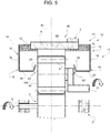
- the embodiment shown in figure 5 relates to a transmission 40, which differs from the transmission 30 because of some manufacturing details and whose parts are indicated, where possible, with the same reference numbers as the corresponding parts of the transmission 1.
- the coupling element 8 is stably connected to the frame 2 so as to support the ring gear 6 in an axially and angularly fixed position relative to the frame 2 itself, whereas the coupling element 31 extends on the inside of the tubular portion 8B.
- the transmission 40 comprises a collection collector 41, which differs from the collection collector 11 in that the two half-shells 12 are divided from each other along the radial plane 13, are moved apart from each other and from the plane 13, are arranged so as to project on opposite axial sides of the tubular portion 8B, and extend in positions facing the ring gear 6 and the ring gears 10, as shown in figure 5 .
- each half-shell 12 has its own section 15 integrally connected to a respective axial end of the tubular portion 8B, so as to define, with part of the tubular portion 8B itself and of the ring gear 6, a respective concave portion 14.
- one section 15 or both sections 15 is or are directly or indirectly connected to the frame 2.
- Each half-shell 12 has its own concave portion 16 facing the ring gears 10 and its own wall 18, which practically faces the toothing 7 and 9 of the external ring gear 6 and of the ring gears 10.
- each concave portion 16 is arranged with its bottom wall 20 substantially parallel to the axis 5 or slightly inclined relative to the axis 5 itself and, in this specific case, alongside the axes 10A and with its wall 22 extending towards the toothing 7 of the external ring gear 6 and towards the ring gears 10.
- each one of the walls 22 delimits, with the axial surfaces of the ring gears 10, a respective radial inlet passage 42 to let the drawn oil into the relative half-shell 12.
- the passage 42 is tapered in a radial direction towards the external ring gear 6, so as to help the drawn oil get into the relative half-shell 12 as a result of a centrifugal effect and so as to inhibit or obstacle the outflow of oil from the relative half-shell 12 as the speed of rotation of the coupling element 31 and of the ring gears 10 decreases.
- the half-shells 12 defining the collection collector 11 could be different in terms of geometry and/or sizes, but they are always such as to collect and hold the mass of drawn oil, whatever the speed of rotation, and to avoid any kind of return of the mass of drawn oil towards the movable part of the transmission, as the speed of rotation varies.
Landscapes
- Engineering & Computer Science (AREA)
- General Engineering & Computer Science (AREA)
- Mechanical Engineering (AREA)
- General Details Of Gearings (AREA)
- Retarders (AREA)
Claims (15)
- Ein mechanisches Getriebe, umfassend:- einen fixen Lagerrahmen (2);- ein Außenrad (6), welches eine innere Verzahnung hat;- ein Kopplungselement (8B), welches an dem besagten Außenrad (6) fixiert und mit dem besagten Lagerrahmen gekoppelt ist, sodass das besagte Außenrad (6) koaxial zu einer fixen Achse (5) ist;- wenigstens ein Zwischenzahnrad (10), welches mit der inneren Verzahnung des besagten Außenrads (6) in Eingriff steht und drehbar um eine entsprechende Achse (10A) ist, welche parallel zu der fixen Achse (5) ist;- eine Schmiermittelflüssigkeit und einen ringförmigen Verteiler (11), welcher bezüglich des besagten Lagerrahmens (2) fixiert ist und ausgebildet ist, eine geleckte Masse der besagten Schmiermittelflüssigkeit aufzusammeln; wobei der besagte Verteiler (11) wenigstens einen ersten ringförmigen konkaven Abschnitt (14) umfasst, welcher die besagte fixe Achse (5) und das besagte Zwischenzahnrad (10) umgibt, und welcher eine dem besagten Kopplungselement (8B) oder dem besagten Zwischenzahnrad (10) zugewandte Konkavität aufweist und eine Masse der aus dem besagten Zwischenzahnrad (10) und/oder dem besagten Außenrad (6) als Resultat eines zentrifugalen Effekts geleckte Schmiermittelflüssigkeit aufnimmt;dadurch gekennzeichnet, dass der besagte ringförmige Verteiler ferner umfasst:- wenigstens einen zweiten ringförmigen konkaven Abschnitt (16), welcher geeignet ist, eine weitere Masse von geleckter Schmiermittelflüssigkeit aufzunehmen, wobei der besagte zweite ringförmige konkave Abschnitt (16) radial innerhalb des besagten ersten ringförmigen konkaven Abschnitts (14) angeordnet ist, wobei er die besagte Achse (5) umgibt und eine radial nach außen in Richtung des besagten ersten ringförmigen konkaven Abschnitts (14) gewandte Konkavität aufweist und- eine Kanalisierungswand (18) zum Abfangen und Kanalisieren der besagten geleckten Schmiermittelflüssigkeit; wobei die besagte Kanalwand (18) in einer flüssigkeitsdichten Art auf einer Seite mit dem besagten ersten ringförmigen konkaven Abschnitt (14) und auf der gegenüber liegenden Seite mit dem besagten zweiten ringförmigen Abschnitt (16) verbunden ist, um die besagte geleckte Schmiermittelflüssigkeit in Richtung entweder des besagten ersten ringförmigen konkaven Abschnitts (14) oder des besagten zweiten ringförmigen konkaven Abschnitts (16) zu kanalisieren.
- Das Getriebe nach Anspruch 1, dadurch gekennzeichnet, dass die besagten ersten und zweiten ringförmigen konkaven Abschnitte (14, 16) und die besagte Kanalisierungswand (18) integral miteinander verbunden sind.
- Das Getriebe nach Anspruch 2, dadurch gekennzeichnet, dass die besagten ersten und zweiten ringförmigen konkaven Abschnitte (14, 16) und die besagte Kanalisierungswand (18) einen ringförmigen Hohlkörper definieren, welcher in einem einzigen Stück gefertigt ist oder verschiedene unterschiedliche aus demselben Material oder aus unterschiedlichen Materialien gefertigte Teile definieren.
- Das Getriebe nach einem der vorhergehenden Ansprüche, dadurch gekennzeichnet, dass das besagte Außenrad (6) drehbar bezüglich des besagten Rahmens um die besagte erste Achse (5) ist, und dass die besagten ersten und zweiten ringförmigen konkaven Abschnitte (14, 16) und die besagte Kanalisierungswand (18) integral mit dem besagten Rahmen verbunden sind und radial außerhalb des besagten Kopplungselements angeordnet sind.
- Das Getriebe nach Anspruch 4, dadurch gekennzeichnet, dass es zwei der besagten zweiten ringförmigen konkaven Abschnitte (16) umfasst, welche jeweils entlang einer Richtung, die parallel zu der besagten fixen Achse (5) ist, angeordnet sind, wobei die besagten zweiten ringförmigen konkaven Abschnitte (16) miteinander und jeweils mit dem besagten ersten ringförmigen konkaven Abschnitt (14) kommunizieren.
- Das Getriebe nach Anspruch 5, dadurch gekennzeichnet, dass die besagten zweiten ringförmigen konkaven Abschnitte (16) zwischen ihnen eine unidirektionale radiale Eingangspassage für die besagte geleckte Schmiermittelflüssigkeit in den besagten Verteiler begrenzen, wobei die besagte Passage mit wenigstens einer weiteren Passage, welche wenigstens durch das besagte Kopplungselement gemacht ist, kommuniziert.
- Das Getriebe nach Anspruch 6, dadurch gekennzeichnet, dass das besagte Kopplungselement wenigstens zwei Abschnitte und einen Verbindungsbereich, welcher die besagten zwei Abschnitte miteinander verbindet, umfasst, wobei sich die besagte weitere Passage durch den Verbindungsbereich erstreckt.
- Das Getriebe nach Anspruch 6 oder 7, dadurch gekennzeichnet, dass das besagte Kopplungselement wenigstens eine Sammelkammer für die besagte geleckte Schmiermittelflüssigkeit begrenzt, wobei die besagte weitere Passage mit der besagten Sammelkammer kommuniziert.
- Das Getriebe nach Anspruch 8, dadurch gekennzeichnet, dass es ein weiteres Kopplungselement, welches das besagte Zwischenzahnrad mit dem besagten Rahmen koppelt, umfasst, wobei das besagte weitere Kopplungselement eine weitere Sammelkammer für die besagte geleckte Schmiermittelflüssigkeit begrenzt, wobei die besagte weitere Sammelkammer mit der Sammelkammer über die besagte weitere Passage und mit der besagten Passage durch eine Durchgangsöffnung durch das besagte weitere Kopplungselement kommuniziert.
- Das Getriebe nach Anspruch 9, dadurch gekennzeichnet, dass das besagte weitere Kopplungselement wenigstens zwei Abschnitte und einen weiteren Verbindungsbereich, welcher die besagten zwei Abschnitte miteinander verbindet, umfasst, wobei die besagte Öffnung sich durch den besagten Verbindungsbereich erstreckt.
- Das Getriebe nach einem der Ansprüche 1 bis 3, dadurch gekennzeichnet, dass das besagte Außenrad and das besagte Kopplungselement bezüglich des besagten Rahmens fixiert ist, und dass die besagten ersten und zweiten ringförmigen konkaven Abschnitte (14, 16) und die besagte Kanalisierungswand (18) integral mit dem besagten Kopplungselement oder direkt mit dem besagten Rahmen verbunden sind.
- Das Getriebe nach Anspruch 11, dadurch gekennzeichnet, dass es zwei erste ringförmige konkave Abschnitte, zwei zweite ringförmige konkave Abschnitte und entsprechende Kanalisierungswände umfasst, wobei die besagten ersten und zweiten ringförmigen konkaven Abschnitte und die besagten Kanalisierungswände einen ersten und einen zweiten ringförmigen Hohlkörper definieren, wobei die besagten erste und zweiten ringförmigen Hohlkörper auf axial gegenüber liegenden Seiten des besagten Außenrads angeordnet sind.
- Das Getriebe nach Anspruch 12, dadurch gekennzeichnet, dass die besagten Kanalisierungswände sich wenigstens teilweise in eine der besagten inneren Verzahnung zugewandte Position erstrecken.
- Das Getriebe nach Anspruch 12 oder 13, dadurch gekennzeichnet, dass die besagten zweiten ringförmigen konkaven Abschnitte sich wenigstens teilweise in eine dem besagten Zwischenzahnrad zugewandte Position erstrecken.
- Das Getriebe nach einem der Ansprüche 12 bis 14, dadurch gekennzeichnet, dass wenigstens einer der besagten zweiten ringförmigen konkaven Abschnitte mit dem besagten Zwischenzahnrad eine Eingangsleitung für die besagte geleckte Schmiermittelflüssigkeit in den besagten ringförmigen Verteiler begrenzen.
Applications Claiming Priority (2)
| Application Number | Priority Date | Filing Date | Title |
|---|---|---|---|
| ITTO20140624 | 2014-08-01 | ||
| PCT/IB2015/055890 WO2016016877A1 (en) | 2014-08-01 | 2015-08-03 | Mechanical gear transmission |
Publications (2)
| Publication Number | Publication Date |
|---|---|
| EP3175148A1 EP3175148A1 (de) | 2017-06-07 |
| EP3175148B1 true EP3175148B1 (de) | 2019-11-13 |
Family
ID=51655924
Family Applications (1)
| Application Number | Title | Priority Date | Filing Date |
|---|---|---|---|
| EP15760282.2A Active EP3175148B1 (de) | 2014-08-01 | 2015-08-03 | Mechanisches getriebe |
Country Status (6)
| Country | Link |
|---|---|
| US (1) | US10208849B2 (de) |
| EP (1) | EP3175148B1 (de) |
| JP (1) | JP6622790B2 (de) |
| CN (1) | CN106574707B (de) |
| CA (1) | CA2956059A1 (de) |
| WO (1) | WO2016016877A1 (de) |
Families Citing this family (5)
| Publication number | Priority date | Publication date | Assignee | Title |
|---|---|---|---|---|
| EP3473892A1 (de) | 2017-10-18 | 2019-04-24 | Ge Avio S.r.l. | Getriebe für einen gasturbinenmotor |
| EP3473893B1 (de) | 2017-10-19 | 2020-06-17 | Ge Avio S.r.l. | Schmierfluidsammlung in einem getriebe eines gasturbinenmotors |
| FR3081513B1 (fr) * | 2018-05-28 | 2021-06-18 | Safran Aircraft Engines | Systeme de transmission de puissance comprenant un dispositif de recuperation d'huile de lubrification et turbomachine equipee d'un tel systeme de transmission de puissance |
| FR3110194B1 (fr) * | 2020-05-13 | 2022-11-18 | Safran Aircraft Engines | Turbomachine d’aeronef comprenant un dispositif de lubrification d’un palier |
| FR3137720B1 (fr) * | 2022-07-07 | 2024-09-20 | Safran Aircraft Engines | Dispositif de recuperation d’huile pour une turbomachine |
Family Cites Families (10)
| Publication number | Priority date | Publication date | Assignee | Title |
|---|---|---|---|---|
| DE376381C (de) | 1920-08-03 | 1923-05-28 | Luftfahrzeugbau Schuette Lanz | Umlaufschmierung, insbesondere fuer Umlaufraedergetriebe |
| GB549207A (en) | 1941-04-09 | 1942-11-11 | Norman Sinclair Mcnab | Improvements in and relating to anti-friction bearings |
| DE2804811A1 (de) | 1978-02-04 | 1979-08-09 | Bosch Gmbh Robert | Vorrichtung zur langzeitschmierung von lagerelementen |
| GB2234035B (en) * | 1989-07-21 | 1993-05-12 | Rolls Royce Plc | A reduction gear assembly and a gas turbine engine |
| US6223616B1 (en) * | 1999-12-22 | 2001-05-01 | United Technologies Corporation | Star gear system with lubrication circuit and lubrication method therefor |
| BE1016742A3 (nl) * | 2005-08-31 | 2007-05-08 | Hansen Transmissions Int | Een planetaire tandwielconstrucie. |
| US8753243B2 (en) * | 2006-08-15 | 2014-06-17 | United Technologies Corporation | Ring gear mounting arrangement with oil scavenge scheme |
| CN201818770U (zh) * | 2010-08-20 | 2011-05-04 | 上海市离心机械研究所有限公司 | 一种差速器的冷却结构 |
| US9404420B2 (en) * | 2012-02-23 | 2016-08-02 | Snecma | Device for recovering lubricating oil from an epicyclic reduction gear |
| EP2946131B1 (de) * | 2013-01-15 | 2020-03-04 | United Technologies Corporation | Getriebeturbinenmotor |
-
2015
- 2015-08-03 US US15/501,067 patent/US10208849B2/en active Active
- 2015-08-03 CN CN201580041627.4A patent/CN106574707B/zh active Active
- 2015-08-03 CA CA2956059A patent/CA2956059A1/en not_active Abandoned
- 2015-08-03 WO PCT/IB2015/055890 patent/WO2016016877A1/en not_active Ceased
- 2015-08-03 JP JP2017505470A patent/JP6622790B2/ja not_active Expired - Fee Related
- 2015-08-03 EP EP15760282.2A patent/EP3175148B1/de active Active
Non-Patent Citations (1)
| Title |
|---|
| None * |
Also Published As
| Publication number | Publication date |
|---|---|
| EP3175148A1 (de) | 2017-06-07 |
| CN106574707B (zh) | 2019-07-16 |
| WO2016016877A1 (en) | 2016-02-04 |
| CA2956059A1 (en) | 2016-02-04 |
| US10208849B2 (en) | 2019-02-19 |
| JP6622790B2 (ja) | 2019-12-18 |
| CN106574707A (zh) | 2017-04-19 |
| US20170254407A1 (en) | 2017-09-07 |
| JP2017523361A (ja) | 2017-08-17 |
Similar Documents
| Publication | Publication Date | Title |
|---|---|---|
| US10208849B2 (en) | Mechanical gear transmission | |
| JP5626455B2 (ja) | 動力伝達装置 | |
| RU2013158716A (ru) | Система смазки редуктора | |
| RU2621854C2 (ru) | Устройство приводного вала газотурбинного двигателя, газотурбинный двигатель и воздушное судно | |
| RU2627990C2 (ru) | Редуктор с эпициклоидной передачей, вентиляторный модуль двухконтурного турбореактивного двигателя и двухконтурный турбореактивный двигатель | |
| US20170030457A1 (en) | Gear baffle | |
| EP3055533B1 (de) | Vorrichtung zur übertragung von öl zwischen zwei sich relativ zueinander drehenden behältern sowie propellerturbomaschine für ein flugzeug mit solch einer vorrichtung | |
| JP6390786B2 (ja) | デファレンシャル装置 | |
| RU2016112949A (ru) | Вращающийся узел, содержащий передаточный механизм и систему распределения масла | |
| BR112016025018B1 (pt) | Módulo de turbomáquina que compreende um cárter em torno de um equipamento com um capô de recuperação de óleo de lubrificação | |
| WO2020245529A1 (fr) | Reducteur planetaire pour une turbomachine d'aeronef | |
| US10563749B2 (en) | Power transmission device | |
| US20100009800A1 (en) | Device for optimizing the feed function of the ring gear of a differential with regard to the maximum flow rate | |
| CN107110424B (zh) | 涡轮机设备的润滑油收集帽 | |
| CN104603503A (zh) | 插接轴系统、具有插接轴系统的差速器、在变速器的轴系统中的导油装置和用于对轴进行上油的钢质集油盘 | |
| CN209540466U (zh) | 一种均分滑油轴承润滑装置 | |
| RU2506460C1 (ru) | Химический горизонтальный электронасосный агрегат | |
| EP1728975B1 (de) | Verbessertes Hubschraubergetriebe | |
| CN102147006B (zh) | 变速箱润滑油分配器 | |
| CN109681619A (zh) | 一种变速箱的配油系统及配油盘总成 | |
| CN102444777A (zh) | 特别用于直升机润滑的泵组件 | |
| JP2009138769A (ja) | 管路接続構造および変速機 | |
| CN205190699U (zh) | 带气压平衡和喷油润滑结构的减速器 | |
| RU2506461C1 (ru) | Химический горизонтальный электронасосный агрегат (варианты) | |
| CN206468790U (zh) | 行星减速机润滑装置 |
Legal Events
| Date | Code | Title | Description |
|---|---|---|---|
| STAA | Information on the status of an ep patent application or granted ep patent |
Free format text: STATUS: THE INTERNATIONAL PUBLICATION HAS BEEN MADE |
|
| 17P | Request for examination filed |
Effective date: 20170119 |
|
| AK | Designated contracting states |
Kind code of ref document: A1 Designated state(s): AL AT BE BG CH CY CZ DE DK EE ES FI FR GB GR HR HU IE IS IT LI LT LU LV MC MK MT NL NO PL PT RO RS SE SI SK SM TR |
|
| AX | Request for extension of the european patent |
Extension state: BA ME |
|
| PUAI | Public reference made under article 153(3) epc to a published international application that has entered the european phase |
Free format text: ORIGINAL CODE: 0009012 |
|
| STAA | Information on the status of an ep patent application or granted ep patent |
Free format text: STATUS: REQUEST FOR EXAMINATION WAS MADE |
|
| DAV | Request for validation of the european patent (deleted) | ||
| DAX | Request for extension of the european patent (deleted) | ||
| GRAP | Despatch of communication of intention to grant a patent |
Free format text: ORIGINAL CODE: EPIDOSNIGR1 |
|
| STAA | Information on the status of an ep patent application or granted ep patent |
Free format text: STATUS: GRANT OF PATENT IS INTENDED |
|
| INTG | Intention to grant announced |
Effective date: 20190619 |
|
| GRAS | Grant fee paid |
Free format text: ORIGINAL CODE: EPIDOSNIGR3 |
|
| GRAA | (expected) grant |
Free format text: ORIGINAL CODE: 0009210 |
|
| STAA | Information on the status of an ep patent application or granted ep patent |
Free format text: STATUS: THE PATENT HAS BEEN GRANTED |
|
| AK | Designated contracting states |
Kind code of ref document: B1 Designated state(s): AL AT BE BG CH CY CZ DE DK EE ES FI FR GB GR HR HU IE IS IT LI LT LU LV MC MK MT NL NO PL PT RO RS SE SI SK SM TR |
|
| REG | Reference to a national code |
Ref country code: CH Ref legal event code: EP Ref country code: AT Ref legal event code: REF Ref document number: 1201996 Country of ref document: AT Kind code of ref document: T Effective date: 20191115 |
|
| REG | Reference to a national code |
Ref country code: DE Ref legal event code: R096 Ref document number: 602015041682 Country of ref document: DE |
|
| REG | Reference to a national code |
Ref country code: IE Ref legal event code: FG4D |
|
| REG | Reference to a national code |
Ref country code: NL Ref legal event code: MP Effective date: 20191113 |
|
| REG | Reference to a national code |
Ref country code: LT Ref legal event code: MG4D |
|
| PG25 | Lapsed in a contracting state [announced via postgrant information from national office to epo] |
Ref country code: NO Free format text: LAPSE BECAUSE OF FAILURE TO SUBMIT A TRANSLATION OF THE DESCRIPTION OR TO PAY THE FEE WITHIN THE PRESCRIBED TIME-LIMIT Effective date: 20200213 Ref country code: BG Free format text: LAPSE BECAUSE OF FAILURE TO SUBMIT A TRANSLATION OF THE DESCRIPTION OR TO PAY THE FEE WITHIN THE PRESCRIBED TIME-LIMIT Effective date: 20200213 Ref country code: FI Free format text: LAPSE BECAUSE OF FAILURE TO SUBMIT A TRANSLATION OF THE DESCRIPTION OR TO PAY THE FEE WITHIN THE PRESCRIBED TIME-LIMIT Effective date: 20191113 Ref country code: LV Free format text: LAPSE BECAUSE OF FAILURE TO SUBMIT A TRANSLATION OF THE DESCRIPTION OR TO PAY THE FEE WITHIN THE PRESCRIBED TIME-LIMIT Effective date: 20191113 Ref country code: SE Free format text: LAPSE BECAUSE OF FAILURE TO SUBMIT A TRANSLATION OF THE DESCRIPTION OR TO PAY THE FEE WITHIN THE PRESCRIBED TIME-LIMIT Effective date: 20191113 Ref country code: PT Free format text: LAPSE BECAUSE OF FAILURE TO SUBMIT A TRANSLATION OF THE DESCRIPTION OR TO PAY THE FEE WITHIN THE PRESCRIBED TIME-LIMIT Effective date: 20200313 Ref country code: LT Free format text: LAPSE BECAUSE OF FAILURE TO SUBMIT A TRANSLATION OF THE DESCRIPTION OR TO PAY THE FEE WITHIN THE PRESCRIBED TIME-LIMIT Effective date: 20191113 Ref country code: GR Free format text: LAPSE BECAUSE OF FAILURE TO SUBMIT A TRANSLATION OF THE DESCRIPTION OR TO PAY THE FEE WITHIN THE PRESCRIBED TIME-LIMIT Effective date: 20200214 Ref country code: PL Free format text: LAPSE BECAUSE OF FAILURE TO SUBMIT A TRANSLATION OF THE DESCRIPTION OR TO PAY THE FEE WITHIN THE PRESCRIBED TIME-LIMIT Effective date: 20191113 Ref country code: NL Free format text: LAPSE BECAUSE OF FAILURE TO SUBMIT A TRANSLATION OF THE DESCRIPTION OR TO PAY THE FEE WITHIN THE PRESCRIBED TIME-LIMIT Effective date: 20191113 |
|
| PG25 | Lapsed in a contracting state [announced via postgrant information from national office to epo] |
Ref country code: IS Free format text: LAPSE BECAUSE OF FAILURE TO SUBMIT A TRANSLATION OF THE DESCRIPTION OR TO PAY THE FEE WITHIN THE PRESCRIBED TIME-LIMIT Effective date: 20200313 Ref country code: RS Free format text: LAPSE BECAUSE OF FAILURE TO SUBMIT A TRANSLATION OF THE DESCRIPTION OR TO PAY THE FEE WITHIN THE PRESCRIBED TIME-LIMIT Effective date: 20191113 Ref country code: HR Free format text: LAPSE BECAUSE OF FAILURE TO SUBMIT A TRANSLATION OF THE DESCRIPTION OR TO PAY THE FEE WITHIN THE PRESCRIBED TIME-LIMIT Effective date: 20191113 |
|
| PG25 | Lapsed in a contracting state [announced via postgrant information from national office to epo] |
Ref country code: AL Free format text: LAPSE BECAUSE OF FAILURE TO SUBMIT A TRANSLATION OF THE DESCRIPTION OR TO PAY THE FEE WITHIN THE PRESCRIBED TIME-LIMIT Effective date: 20191113 |
|
| PG25 | Lapsed in a contracting state [announced via postgrant information from national office to epo] |
Ref country code: DK Free format text: LAPSE BECAUSE OF FAILURE TO SUBMIT A TRANSLATION OF THE DESCRIPTION OR TO PAY THE FEE WITHIN THE PRESCRIBED TIME-LIMIT Effective date: 20191113 Ref country code: EE Free format text: LAPSE BECAUSE OF FAILURE TO SUBMIT A TRANSLATION OF THE DESCRIPTION OR TO PAY THE FEE WITHIN THE PRESCRIBED TIME-LIMIT Effective date: 20191113 Ref country code: RO Free format text: LAPSE BECAUSE OF FAILURE TO SUBMIT A TRANSLATION OF THE DESCRIPTION OR TO PAY THE FEE WITHIN THE PRESCRIBED TIME-LIMIT Effective date: 20191113 Ref country code: CZ Free format text: LAPSE BECAUSE OF FAILURE TO SUBMIT A TRANSLATION OF THE DESCRIPTION OR TO PAY THE FEE WITHIN THE PRESCRIBED TIME-LIMIT Effective date: 20191113 |
|
| REG | Reference to a national code |
Ref country code: DE Ref legal event code: R097 Ref document number: 602015041682 Country of ref document: DE |
|
| REG | Reference to a national code |
Ref country code: AT Ref legal event code: MK05 Ref document number: 1201996 Country of ref document: AT Kind code of ref document: T Effective date: 20191113 |
|
| PG25 | Lapsed in a contracting state [announced via postgrant information from national office to epo] |
Ref country code: SM Free format text: LAPSE BECAUSE OF FAILURE TO SUBMIT A TRANSLATION OF THE DESCRIPTION OR TO PAY THE FEE WITHIN THE PRESCRIBED TIME-LIMIT Effective date: 20191113 Ref country code: SK Free format text: LAPSE BECAUSE OF FAILURE TO SUBMIT A TRANSLATION OF THE DESCRIPTION OR TO PAY THE FEE WITHIN THE PRESCRIBED TIME-LIMIT Effective date: 20191113 |
|
| PLBE | No opposition filed within time limit |
Free format text: ORIGINAL CODE: 0009261 |
|
| STAA | Information on the status of an ep patent application or granted ep patent |
Free format text: STATUS: NO OPPOSITION FILED WITHIN TIME LIMIT |
|
| 26N | No opposition filed |
Effective date: 20200814 |
|
| PG25 | Lapsed in a contracting state [announced via postgrant information from national office to epo] |
Ref country code: ES Free format text: LAPSE BECAUSE OF FAILURE TO SUBMIT A TRANSLATION OF THE DESCRIPTION OR TO PAY THE FEE WITHIN THE PRESCRIBED TIME-LIMIT Effective date: 20191113 |
|
| PG25 | Lapsed in a contracting state [announced via postgrant information from national office to epo] |
Ref country code: AT Free format text: LAPSE BECAUSE OF FAILURE TO SUBMIT A TRANSLATION OF THE DESCRIPTION OR TO PAY THE FEE WITHIN THE PRESCRIBED TIME-LIMIT Effective date: 20191113 Ref country code: SI Free format text: LAPSE BECAUSE OF FAILURE TO SUBMIT A TRANSLATION OF THE DESCRIPTION OR TO PAY THE FEE WITHIN THE PRESCRIBED TIME-LIMIT Effective date: 20191113 |
|
| PG25 | Lapsed in a contracting state [announced via postgrant information from national office to epo] |
Ref country code: IT Free format text: LAPSE BECAUSE OF FAILURE TO SUBMIT A TRANSLATION OF THE DESCRIPTION OR TO PAY THE FEE WITHIN THE PRESCRIBED TIME-LIMIT Effective date: 20191113 |
|
| REG | Reference to a national code |
Ref country code: DE Ref legal event code: R119 Ref document number: 602015041682 Country of ref document: DE |
|
| PG25 | Lapsed in a contracting state [announced via postgrant information from national office to epo] |
Ref country code: MC Free format text: LAPSE BECAUSE OF FAILURE TO SUBMIT A TRANSLATION OF THE DESCRIPTION OR TO PAY THE FEE WITHIN THE PRESCRIBED TIME-LIMIT Effective date: 20191113 |
|
| REG | Reference to a national code |
Ref country code: CH Ref legal event code: PL |
|
| GBPC | Gb: european patent ceased through non-payment of renewal fee |
Effective date: 20200803 |
|
| PG25 | Lapsed in a contracting state [announced via postgrant information from national office to epo] |
Ref country code: CH Free format text: LAPSE BECAUSE OF NON-PAYMENT OF DUE FEES Effective date: 20200831 Ref country code: LU Free format text: LAPSE BECAUSE OF NON-PAYMENT OF DUE FEES Effective date: 20200803 Ref country code: LI Free format text: LAPSE BECAUSE OF NON-PAYMENT OF DUE FEES Effective date: 20200831 |
|
| REG | Reference to a national code |
Ref country code: BE Ref legal event code: MM Effective date: 20200831 |
|
| PG25 | Lapsed in a contracting state [announced via postgrant information from national office to epo] |
Ref country code: DE Free format text: LAPSE BECAUSE OF NON-PAYMENT OF DUE FEES Effective date: 20210302 Ref country code: FR Free format text: LAPSE BECAUSE OF NON-PAYMENT OF DUE FEES Effective date: 20200831 |
|
| PG25 | Lapsed in a contracting state [announced via postgrant information from national office to epo] |
Ref country code: IE Free format text: LAPSE BECAUSE OF NON-PAYMENT OF DUE FEES Effective date: 20200803 Ref country code: GB Free format text: LAPSE BECAUSE OF NON-PAYMENT OF DUE FEES Effective date: 20200803 Ref country code: BE Free format text: LAPSE BECAUSE OF NON-PAYMENT OF DUE FEES Effective date: 20200831 |
|
| PG25 | Lapsed in a contracting state [announced via postgrant information from national office to epo] |
Ref country code: TR Free format text: LAPSE BECAUSE OF FAILURE TO SUBMIT A TRANSLATION OF THE DESCRIPTION OR TO PAY THE FEE WITHIN THE PRESCRIBED TIME-LIMIT Effective date: 20191113 Ref country code: MT Free format text: LAPSE BECAUSE OF FAILURE TO SUBMIT A TRANSLATION OF THE DESCRIPTION OR TO PAY THE FEE WITHIN THE PRESCRIBED TIME-LIMIT Effective date: 20191113 Ref country code: CY Free format text: LAPSE BECAUSE OF FAILURE TO SUBMIT A TRANSLATION OF THE DESCRIPTION OR TO PAY THE FEE WITHIN THE PRESCRIBED TIME-LIMIT Effective date: 20191113 |
|
| PG25 | Lapsed in a contracting state [announced via postgrant information from national office to epo] |
Ref country code: MK Free format text: LAPSE BECAUSE OF FAILURE TO SUBMIT A TRANSLATION OF THE DESCRIPTION OR TO PAY THE FEE WITHIN THE PRESCRIBED TIME-LIMIT Effective date: 20191113 |
|
| P01 | Opt-out of the competence of the unified patent court (upc) registered |
Effective date: 20230418 |