EP3174177B1 - Charging system and charging start control method - Google Patents
Charging system and charging start control method Download PDFInfo
- Publication number
- EP3174177B1 EP3174177B1 EP16814359.2A EP16814359A EP3174177B1 EP 3174177 B1 EP3174177 B1 EP 3174177B1 EP 16814359 A EP16814359 A EP 16814359A EP 3174177 B1 EP3174177 B1 EP 3174177B1
- Authority
- EP
- European Patent Office
- Prior art keywords
- charging
- user
- vehicle information
- control unit
- input
- Prior art date
- Legal status (The legal status is an assumption and is not a legal conclusion. Google has not performed a legal analysis and makes no representation as to the accuracy of the status listed.)
- Active
Links
Images



Classifications
-
- B—PERFORMING OPERATIONS; TRANSPORTING
- B60—VEHICLES IN GENERAL
- B60L—PROPULSION OF ELECTRICALLY-PROPELLED VEHICLES; SUPPLYING ELECTRIC POWER FOR AUXILIARY EQUIPMENT OF ELECTRICALLY-PROPELLED VEHICLES; ELECTRODYNAMIC BRAKE SYSTEMS FOR VEHICLES IN GENERAL; MAGNETIC SUSPENSION OR LEVITATION FOR VEHICLES; MONITORING OPERATING VARIABLES OF ELECTRICALLY-PROPELLED VEHICLES; ELECTRIC SAFETY DEVICES FOR ELECTRICALLY-PROPELLED VEHICLES
- B60L53/00—Methods of charging batteries, specially adapted for electric vehicles; Charging stations or on-board charging equipment therefor; Exchange of energy storage elements in electric vehicles
- B60L53/10—Methods of charging batteries, specially adapted for electric vehicles; Charging stations or on-board charging equipment therefor; Exchange of energy storage elements in electric vehicles characterised by the energy transfer between the charging station and the vehicle
- B60L53/14—Conductive energy transfer
-
- B—PERFORMING OPERATIONS; TRANSPORTING
- B60—VEHICLES IN GENERAL
- B60L—PROPULSION OF ELECTRICALLY-PROPELLED VEHICLES; SUPPLYING ELECTRIC POWER FOR AUXILIARY EQUIPMENT OF ELECTRICALLY-PROPELLED VEHICLES; ELECTRODYNAMIC BRAKE SYSTEMS FOR VEHICLES IN GENERAL; MAGNETIC SUSPENSION OR LEVITATION FOR VEHICLES; MONITORING OPERATING VARIABLES OF ELECTRICALLY-PROPELLED VEHICLES; ELECTRIC SAFETY DEVICES FOR ELECTRICALLY-PROPELLED VEHICLES
- B60L53/00—Methods of charging batteries, specially adapted for electric vehicles; Charging stations or on-board charging equipment therefor; Exchange of energy storage elements in electric vehicles
- B60L53/30—Constructional details of charging stations
- B60L53/31—Charging columns specially adapted for electric vehicles
-
- B—PERFORMING OPERATIONS; TRANSPORTING
- B60—VEHICLES IN GENERAL
- B60L—PROPULSION OF ELECTRICALLY-PROPELLED VEHICLES; SUPPLYING ELECTRIC POWER FOR AUXILIARY EQUIPMENT OF ELECTRICALLY-PROPELLED VEHICLES; ELECTRODYNAMIC BRAKE SYSTEMS FOR VEHICLES IN GENERAL; MAGNETIC SUSPENSION OR LEVITATION FOR VEHICLES; MONITORING OPERATING VARIABLES OF ELECTRICALLY-PROPELLED VEHICLES; ELECTRIC SAFETY DEVICES FOR ELECTRICALLY-PROPELLED VEHICLES
- B60L53/00—Methods of charging batteries, specially adapted for electric vehicles; Charging stations or on-board charging equipment therefor; Exchange of energy storage elements in electric vehicles
- B60L53/60—Monitoring or controlling charging stations
- B60L53/65—Monitoring or controlling charging stations involving identification of vehicles or their battery types
-
- G—PHYSICS
- G05—CONTROLLING; REGULATING
- G05B—CONTROL OR REGULATING SYSTEMS IN GENERAL; FUNCTIONAL ELEMENTS OF SUCH SYSTEMS; MONITORING OR TESTING ARRANGEMENTS FOR SUCH SYSTEMS OR ELEMENTS
- G05B15/00—Systems controlled by a computer
- G05B15/02—Systems controlled by a computer electric
-
- H—ELECTRICITY
- H02—GENERATION; CONVERSION OR DISTRIBUTION OF ELECTRIC POWER
- H02J—ELECTRIC POWER NETWORKS; CIRCUIT ARRANGEMENTS OR SYSTEMS FOR SUPPLYING OR DISTRIBUTING ELECTRIC POWER; SYSTEMS FOR STORING ELECTRIC ENERGY
- H02J7/00—Circuit arrangements for charging or discharging batteries or for supplying loads from batteries
-
- H—ELECTRICITY
- H02—GENERATION; CONVERSION OR DISTRIBUTION OF ELECTRIC POWER
- H02J—ELECTRIC POWER NETWORKS; CIRCUIT ARRANGEMENTS OR SYSTEMS FOR SUPPLYING OR DISTRIBUTING ELECTRIC POWER; SYSTEMS FOR STORING ELECTRIC ENERGY
- H02J7/00—Circuit arrangements for charging or discharging batteries or for supplying loads from batteries
- H02J7/70—Circuit arrangements for charging or discharging batteries or for supplying loads from batteries characterised by the mechanical construction
- H02J7/751—Circuit arrangements for charging or discharging batteries or for supplying loads from batteries characterised by the mechanical construction concerning the insertion or the connection of the batteries
-
- Y—GENERAL TAGGING OF NEW TECHNOLOGICAL DEVELOPMENTS; GENERAL TAGGING OF CROSS-SECTIONAL TECHNOLOGIES SPANNING OVER SEVERAL SECTIONS OF THE IPC; TECHNICAL SUBJECTS COVERED BY FORMER USPC CROSS-REFERENCE ART COLLECTIONS [XRACs] AND DIGESTS
- Y02—TECHNOLOGIES OR APPLICATIONS FOR MITIGATION OR ADAPTATION AGAINST CLIMATE CHANGE
- Y02T—CLIMATE CHANGE MITIGATION TECHNOLOGIES RELATED TO TRANSPORTATION
- Y02T10/00—Road transport of goods or passengers
- Y02T10/60—Other road transportation technologies with climate change mitigation effect
- Y02T10/70—Energy storage systems for electromobility, e.g. batteries
-
- Y—GENERAL TAGGING OF NEW TECHNOLOGICAL DEVELOPMENTS; GENERAL TAGGING OF CROSS-SECTIONAL TECHNOLOGIES SPANNING OVER SEVERAL SECTIONS OF THE IPC; TECHNICAL SUBJECTS COVERED BY FORMER USPC CROSS-REFERENCE ART COLLECTIONS [XRACs] AND DIGESTS
- Y02—TECHNOLOGIES OR APPLICATIONS FOR MITIGATION OR ADAPTATION AGAINST CLIMATE CHANGE
- Y02T—CLIMATE CHANGE MITIGATION TECHNOLOGIES RELATED TO TRANSPORTATION
- Y02T10/00—Road transport of goods or passengers
- Y02T10/60—Other road transportation technologies with climate change mitigation effect
- Y02T10/7072—Electromobility specific charging systems or methods for batteries, ultracapacitors, supercapacitors or double-layer capacitors
-
- Y—GENERAL TAGGING OF NEW TECHNOLOGICAL DEVELOPMENTS; GENERAL TAGGING OF CROSS-SECTIONAL TECHNOLOGIES SPANNING OVER SEVERAL SECTIONS OF THE IPC; TECHNICAL SUBJECTS COVERED BY FORMER USPC CROSS-REFERENCE ART COLLECTIONS [XRACs] AND DIGESTS
- Y02—TECHNOLOGIES OR APPLICATIONS FOR MITIGATION OR ADAPTATION AGAINST CLIMATE CHANGE
- Y02T—CLIMATE CHANGE MITIGATION TECHNOLOGIES RELATED TO TRANSPORTATION
- Y02T90/00—Enabling technologies or technologies with a potential or indirect contribution to GHG emissions mitigation
- Y02T90/10—Technologies relating to charging of electric vehicles
- Y02T90/12—Electric charging stations
-
- Y—GENERAL TAGGING OF NEW TECHNOLOGICAL DEVELOPMENTS; GENERAL TAGGING OF CROSS-SECTIONAL TECHNOLOGIES SPANNING OVER SEVERAL SECTIONS OF THE IPC; TECHNICAL SUBJECTS COVERED BY FORMER USPC CROSS-REFERENCE ART COLLECTIONS [XRACs] AND DIGESTS
- Y02—TECHNOLOGIES OR APPLICATIONS FOR MITIGATION OR ADAPTATION AGAINST CLIMATE CHANGE
- Y02T—CLIMATE CHANGE MITIGATION TECHNOLOGIES RELATED TO TRANSPORTATION
- Y02T90/00—Enabling technologies or technologies with a potential or indirect contribution to GHG emissions mitigation
- Y02T90/10—Technologies relating to charging of electric vehicles
- Y02T90/14—Plug-in electric vehicles
-
- Y—GENERAL TAGGING OF NEW TECHNOLOGICAL DEVELOPMENTS; GENERAL TAGGING OF CROSS-SECTIONAL TECHNOLOGIES SPANNING OVER SEVERAL SECTIONS OF THE IPC; TECHNICAL SUBJECTS COVERED BY FORMER USPC CROSS-REFERENCE ART COLLECTIONS [XRACs] AND DIGESTS
- Y02—TECHNOLOGIES OR APPLICATIONS FOR MITIGATION OR ADAPTATION AGAINST CLIMATE CHANGE
- Y02T—CLIMATE CHANGE MITIGATION TECHNOLOGIES RELATED TO TRANSPORTATION
- Y02T90/00—Enabling technologies or technologies with a potential or indirect contribution to GHG emissions mitigation
- Y02T90/10—Technologies relating to charging of electric vehicles
- Y02T90/16—Information or communication technologies improving the operation of electric vehicles
Definitions
- the present invention relates to a charging system capable of charging a plurality of electric vehicles of different charging standards, and a charging start control method of the charging system.
- Conventionally known charging apparatus is recited in, for example, JP-A-2014-183739 , which is capable of charging a plurality of electric vehicles compliant with different charging standards (charging protocols).
- the charging apparatus recited in Patent Document 1 includes a charging connector compliant with the SAE standard, a charging connector compliant with the CHAdeMO standard, and a selection switch for a user to select one of the SAE standard and the CHAdeMO standard and unlock the charging connector compliant with the selected charging standard. Accordingly, this charging apparatus enables a CHAdeMO standard-compliant electric vehicle and a SAE standard-compliant electric vehicle to be charged by one apparatus.
- US 2014/266042 A1 discloses a charging unit for an electric vehicle which includes a charging circuit which is constructed and arranged for delivering on a selectable basis one of two Level 3 charges, the selection being made by the user by way of a selection switch.
- the selection switch is integrated with the corresponding circuitry for selecting either a SAE protocol for charging the electric vehicle or a CHAdeMO protocol for charging the electric vehicle.
- This document further discloses a user-selected charging protocol and means for alerting the user in case the selected charging cable and the selected charging standard do not coincide.
- JP 2010 028913 A discloses a charging system for electric powered vehicles that improves the utilization efficiency of a charging device and reduces initial cost and an operating cost.
- the charging system has information input means enabling input of charge instruction information, information displays means, and fee collecting means for collecting fee from the user.
- the charging system stores charge instruction information input from the information input means, computes charge reservation information including estimated charge start time, estimated charge end time, and charging fee, and sets a time for which the power supplying means is available.
- a control unit displays the charge reservation information.
- the above conventional charging apparatus requires a user to select a charging standard each time to not only make operation complicated but also possibly invite erroneous selection of a charging standard, and in such a case, no charging is allowed to make the user feel inconvenience.
- the present invention has been made in view of the above circumstances and aims to provide a charging system with improved convenience and a charging start control method of the charging system.
- a charging system is a charging system including a charging apparatus which charges a plurality of electric vehicles compliant with different charging standards, and a data base in which identification information for identifying a user of the charging apparatus and vehicle information related to the user's electric vehicle are stored so as to be associated with each other,
- the charging apparatus includes a charging apparatus main body including a power supply unit and a control unit, the power supply unit conducting charging operation under the control of the control unit; and a plurality of charging connectors compliant with different charging standards which is switched between a state of being locked in the charging apparatus main body and an unlocked state under the control of the control unit, the control unit executing reception processing of receiving an input of the identification information from a user; authentication processing of communicating with the data base to conduct authentication of the identification information input in the reception processing; first determination processing of determining a charging standard on the basis of the vehicle information associated with the identification information when the authentication succeeds; and unlocking/notification processing of unlocking a charging connector compliant with a charging
- control unit of the charging apparatus determines a charging standard on the basis of the vehicle information, such inconvenience can be eliminated as a failure of charging because of user's erroneous selection of a charging standard. Additionally, according to this configuration, since the control unit notifies the user of unlocking so as to allow the user to identify an unlocked charging connector, such inconvenience can be eliminated as prevents the user from finding which of the charging connectors is unlocked.
- the control unit executes second determination processing of receiving an input of the vehicle information from a user and determining a charging standard on the basis of the input vehicle information when the authentication fails in the authentication processing, and in the unlocking/notification processing, unlocks a charging connector compliant with a charging standard determined by the first determination processing or by the second determination processing among the plurality of charging connectors, and notifies of unlocking so as to allow the user to identify the unlocked charging connector.
- control unit can be configured to acquire, in the second determination processing, the vehicle information by communication with a user's electric vehicle or acquire the vehicle information by notifying the user of the vehicle information of each of the plurality of electric vehicles to cause the user to select one from the vehicle information.
- control unit can be configured to execute selection processing of causing a user to select a need of change/no need of change of the vehicle information acquired in the first determination processing or in the second determination processing, and when the user selects no need of change, notify the data base of an update of the vehicle information and when the user selects a need of change, execute the second determination processing.
- control unit can be configured to notify the data base of a charging start when causing the power supply unit to start the charging operation
- the data base can be configured to, when receiving the update notification and the charging start notification from the control unit, update the vehicle information associated with the identification information or store the notified vehicle information so as to be associated with the identification information.
- the charging apparatus can be configured to include input receiving means which receives an input of the identification information and the vehicle information from a user and outputs the input identification information and the input vehicle information to the control unit; and lighting means which lights under the control of the control unit for allowing the user to visually identify the unlocked charging connector.
- the charging system can be configured to include a portable information terminal which a user carries, in which the control unit receives an input of the identification information and/or the vehicle information from the portable information terminal to notify the portable information terminal of the unlocking.
- a user is allowed to input identification information and/or vehicle information and to receive a notification of unlocking while sitting in an electric vehicle.
- the charging system can be configured to include a vehicle-mounted information terminal mounted on a user's electric vehicle, in which the control unit receives an input of the identification information and/or the vehicle information from the vehicle-mounted information terminal to notify the vehicle-mounted information terminal of the unlocking.
- a user is allowed to input identification information and/or vehicle information and to receive a notification of unlocking while sitting in an electric vehicle.
- the plurality of charging connectors can be configured to include a plurality of charging connectors for one charging standard
- the control unit can be configured, to, in the unlocking/notification processing, unlock the plurality of charging connectors compliant with a charging standard determined by the first determination processing or by the second determination processing.
- an operating rate of the charging apparatus can be increased. Additionally, according to this configuration, since a plurality of charging connectors is unlocked, a user, when selecting a charging connector, is allowed to have a wider range of selection including, for example, selection of a charging connector located closest to a parking position.
- the charging start control method is a charging start control method of a charging system including a charging apparatus having a plurality of charging connectors compliant with different charging standards to charge a plurality of electric vehicles compliant with different charging standards, and a data base in which identification information for identifying a user of the charging apparatus and vehicle information related to the user's electric vehicle are stored so as to be associated with each other, the method including steps, which are conducted by the charging apparatus, of a reception step of receiving an input of the identification information from a user; an authentication step of communicating with the data base to conduct authentication of the identification information input in the reception step; a first determination step of determining a charging standard on the basis of the vehicle information associated with the identification information when the authentication succeeds; and an unlocking/notification step of switching a charging connector compliant with a charging standard determined by the first determination step among the plurality of charging connectors from a locked state to an unlocked state and notifying the user of unlocking so as to allow the user to identify the unlocked charging connector
- the charging apparatus determines a charging standard on the basis of the vehicle information, such inconvenience can be eliminated as a failure of charging because of user's erroneous selection of a charging standard. Additionally, according to this configuration, since the charging apparatus notifies the user of unlocking so as to allow the user to identify an unlocked charging connector, such inconvenience can be eliminated as prevents the user from finding which of the charging connectors is unlocked.
- the charging start control method preferably further includes a second determination step, which is conducted by the charging apparatus, of receiving an input of the vehicle information from a user and determining a charging standard on the basis of the input vehicle information when the authentication fails in the authentication step, in which in the unlocking/notification step, the charging apparatus switches a charging connector compliant with a charging standard determined by the first determination step or by the second determination step among the plurality of charging connectors from the locked state to the unlocked state and notifies of unlocking so as to allow the user to identify the unlocked charging connector.
- a second determination step which is conducted by the charging apparatus, of receiving an input of the vehicle information from a user and determining a charging standard on the basis of the input vehicle information when the authentication fails in the authentication step, in which in the unlocking/notification step, the charging apparatus switches a charging connector compliant with a charging standard determined by the first determination step or by the second determination step among the plurality of charging connectors from the locked state to the unlocked state and notifies of unlocking so as to allow the user to identify
- a charging system with improved convenience and a charging start control method of the charging system can be provided.
- Fig. 1 shows a charging system 1 according to one embodiment of the present invention.
- the charging system 1 includes a charging apparatus 10 which conducts charging (quick charging) of a plurality of electric vehicles complaint with different charging standards, and a database (storage device) 20.
- the data base 20 stores identification information related to a user of the charging apparatus 10 and vehicle information related to the user's electric vehicle so as to be associated with each other.
- the identification information includes information enabling identification of a user of the charging apparatus 10, e.g. a user ID of a user's authentication card, a one-time password of which a user is notified in advance and the like.
- the vehicle information includes a charging standard of an electric vehicle and /or information enabling the charging standard to be identified, e.g. information about a manufacturer, a type of car, a storage capacity, charging pattern and the like.
- the user Before starting using the charging apparatus 10, e.g. when purchasing an electric vehicle, the user is allowed to store identification information and vehicle information in the data base 20 via the Internet in advance. Additionally, though details will be described later, when the identification information and the vehicle information are stored in the data base 20, the charging apparatus 10 is allowed to update at least the vehicle information after the start of the charging. By contrast, when neither the identification information nor the vehicle information is stored in the data base 20, the charging apparatus 10 is allowed to store the identification information and the vehicle information so as to be associated with each other in the data base 20 after the start of charging. In the present embodiment, although the data base 20 is provided separately from the charging apparatus 10, the data base 20 may be provided inside the charging apparatus 10.
- the charging apparatus 10 includes a charging apparatus main body including a power supply unit 11 and a control unit 12, three charging connectors (charging guns) 13-1 to 13-3 compliant with different charging standards, locking mechanisms 14-1 to 14-3 which lock the charging connectors 13-1 to 13-3 in a gun holder of the charging apparatus main body, lighting means 15-1 to 15-3 provided adjacent to the locking mechanisms 14-1 to 14-3, and input receiving means 16 which receives input information from a user.
- a charging apparatus main body including a power supply unit 11 and a control unit 12, three charging connectors (charging guns) 13-1 to 13-3 compliant with different charging standards, locking mechanisms 14-1 to 14-3 which lock the charging connectors 13-1 to 13-3 in a gun holder of the charging apparatus main body, lighting means 15-1 to 15-3 provided adjacent to the locking mechanisms 14-1 to 14-3, and input receiving means 16 which receives input information from a user.
- the power supply unit 11 generates DC power on the basis of AC power supplied from an alternating current source 2 and supplies the generated DC power to the charging connectors 13-1 to 13-3 via a power line.
- the three charging connectors 13-1 to 13-3 compliant with different charging standards receive a supply of DC power from the single power supply unit 11.
- the power supply unit 11 includes at least one charging unit.
- the charging unit includes, for example, an AC/DC converter, and a control circuit which controls the AC/ DC converter under the control of the control unit 12.
- a relay 17-1 On the power line which connects the power supply unit 11 and the charging connector 13-1, a relay 17-1 is interposed. Additionally, on the power line which connects the power supply unit 11 and the charging connector 13-2, a relay 17-2 is interposed, and on the power line which connects the power supply unit 11 and the charging connector 13-3, a relay 17-3 is interposed. These relays 17-1 to 17-3 are independently switched between an on-state and an off-state under the control of the control unit 12. For example, the relay 17-1 is turned off at a time of non-charging and is turned on at a time of charging (specifically, when locking by the locking mechanism 14-1 is released to be connected to an electric vehicle). This is also the case with the relays 17-2 and 17-3.
- the charging connectors 13-1 to 13-3 are compliant with a plurality of charging standards. Specifically, the charging connectors 13-1 and 13-2 are compliant with a first charging standard A (e.g. the CHAdeMO standard) and the charging connector 13-3 is compliant with a second charging standard B (e.g. the SAE standard). Since the charging connectors 13-1 to 13-3 are locked in the charging apparatus main body by the locking mechanisms 14-1 to 14-3 at the time of not charging, the connectors cannot be connected to an electric vehicle. By contrast, when entering an unlocked state, the charging connectors 13-1 to 13-3 can be connected to the electric vehicle. For example, when the charging connectors 13-1 and 13-2 compliant with the first charging standard A enter the unlocked state, the user selects one of the charging connectors 13-1 and 13-2 to be connected to the electric vehicle.
- a first charging standard A e.g. the CHAdeMO standard
- B e.g. the SAE standard
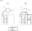
- FIG. 2(A) shows a charging apparatus 10' including one charging connector compliant with the first charging standard A and one charging connector compliant with the second charging standard B.
- Fig. 2 (B) shows the charging apparatus 10 including two charging connectors compliant with the first charging standard A and one charging connector compliant with the second charging standard B. Since the charging apparatus 10' shown in Fig. 2 (A) includes only one charging connector compliant with the first charging standard A, when there are two electric vehicles compliant with the first charging standard A, one electric vehicle cannot be charged even through there is free space for charging. By contrast, since the charging apparatus 10 shown in Fig.
- the charging apparatus 10 shown in Fig. 2(B) includes two charging connectors 13-1 and 13-2 compliant with the first charging standard A, when there is free charging space, the two electric vehicles compliant with the first charging standard A can be both charged.
- the charging apparatus 10 shown in Fig. 2(B) has an increased operating rate.
- the charging apparatus 10 when selecting the charging connector 13-1 or 13-2, the user is allowed to have a wider range of selection such as selection of a connector closer to a parking position, for example.
- the lighting means 15-1 to 15-3 continuously or intermittently light under the control of the control unit 12 for allowing a user to visually identify which of the charging connectors 13-1 to 13-3 is unlocked.
- the lighting means 15-1 and 15-2 light, while the lighting means 15-3 does not light.
- the lighting means 15-1 to 15-3 each include, for example, an LED which emits a visible light.
- the lighting means 15-1 to 15-3 are preferably provided in the vicinity of the corresponding charging connectors 13-1 to 13-3, a position for disposition can be appropriately changed as long as a user can identify an unlocked connector.
- the input receiving means 16 which has a display screen, receives an input of the identification information and the vehicle information from a user on the display screen and outputs the input identification information and vehicle information to the control unit 12. Specifically, when the user holds an authentication card over the input receiving means 16, the input receiving means 16 reads a user ID of the authentication card from the authentication card and outputs the read user ID to the control unit 12.
- the input receiving means 16 includes a liquid crystal touch panel, for example.
- the control unit 12 communicates with the data base 20 via the Internet (e.g. Ethernet (registered trademark)). Additionally, the control unit 12 communicates with each unit of the charging apparatus 10 via, for example, a CAN communication line.
- the Internet e.g. Ethernet (registered trademark)
- the control unit 12 communicates with each unit of the charging apparatus 10 via, for example, a CAN communication line.
- control unit 12 executes:
- the control unit 12 may execute second determination processing of receiving an input of vehicle information from a user and on the basis of the input vehicle information, determining a charging standard, and in the unlocking/notification processing, may unlock usable charging connector(s) 13-1 to 13-3, which is/are the charging connector(s) 13-1 to 13-3 compliant with the charging standard determined by the first determination processing or by the second determination processing among the charging connectors 13-1 to 13-3 and notify of unlocking by the lighting means 15-1 to 15-3 so that a user can identify the unlocked charging connector(s) 13-1 to 13-3.
- control unit 12 executes:
- the charging system 1 eliminates such inconvenience as a failure of charging because of user's erroneous selection of a charging standard because the control unit 12 determines a charging standard on the basis of the vehicle information. Additionally, because the control unit 12 notifies of unlocking by the lighting means 15-1 to 15-3 so that a user can identify the unlocked charging connector(s) 13-1 to 13-3, the charging system 1 according to the present embodiment eliminates such inconvenience as prevents the user from finding which of the charging connectors 13-1 to 13-3 is unlocked, thereby preventing excessive pull-out of the charging connectors 13-1 to 13-3 which is a cause of a failure.
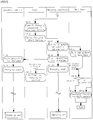
- Fig. 3 to Fig. 5 show flow charts of a charging start control method according to one embodiment of the present invention.
- the charging start control method according to the present embodiment is executed by the charging system 1.
- the control unit 12 causes the input receiving means 16 to display an input screen for identification information, thereby notifying the user of identification information input guidance (S3-1). Specifically, the control unit 12 causes the input receiving means 16 to display a read screen for an authentication card (e.g. an authentication card using RFIC) and an input screen for a one-time password.
- an authentication card e.g. an authentication card using RFIC
- the input receiving means 16 When the user inputs the identification information in the input receiving means 16 (S2-2), the input receiving means 16 outputs the input identification information to the control unit 12.
- the input receiving means 16 In a case where the user's electric vehicle is compliant with the first charging standard A and the user has an authentication card, when the user holds the authentication card over the input receiving means 16, the input receiving means 16 reads a user ID of the authentication card to output the read user ID to the control unit 12.
- the input receiving means 16 In a case where the user's electric vehicle is compliant with the second charging standard B and the user is notified of a one-time password in advance, when the user inputs the one-time password, the input receiving means 16 outputs the input one-time password to the control unit 12.
- the processing from the above S 3-1 to the processing in which the identification information is input to the control unit 12 corresponds to the reception processing and corresponds to the reception step of the charging start control method.
- the control unit 12 may notify of payment of a charging fee together with a notification of identification information input guidance, and in such a case, the user will input the identification information, as well as paying a charging fee.
- the control unit 12 having received the input of the identification information outputs the input identification information to the data base 20, as well as requesting the data base 20 to collate the identification information (S3-2). In other words, the control unit 12 starts authentication of the input identification information.
- the data base 20 having received the collation request starts collation of the identification information (S4-1) and responds to the control unit 12 with a collation result (S4-2). Specifically, when identification information coincident with the input identification information (a user ID or a one-time password) is stored, the data base 20 outputs vehicle information associated with the identification information to the control unit 12. By contrast, when no identification information coincident with the input identification information is stored, the data base 20 outputs, to the control unit 12, a signal indicating that no identification information is coincident with the input identification information. The control unit 12 receives the collation result from the data base 20 (S3-3).
- the control unit 12 having received the collation result determines whether the input identification information is "new” or “existing” on the basis of the collation result (S3-4).
- the control unit 12 determines that the identification information is "new” (new at S3-4), and when vehicle information is input from the data base 20, determines that the identification information is "existing” (existing at S3-4). Determination of "new” by the control unit 12 corresponds to a failure of authentication, and determination of "existing" by the control unit 12 corresponds to a success of authentication.
- the processing of the above S3-2 to S3-4 corresponds to the authentication processing and corresponds to the authentication step of the charging start control method.
- the control unit 12 having made a determination of "new" tries to communicate with a user's electric vehicle by wireless in order to acquire vehicle information.
- the control unit 12 which cannot acquire vehicle information from the electric vehicle, causes the input receiving means 16 to display a vehicle information selection screen (e.g. a catalog of electric vehicles) to notify the user of vehicle information of each of a plurality of electric vehicles (S3-5).
- a vehicle information selection screen e.g. a catalog of electric vehicles
- the control unit 12 determines a charging standard of the charging connector(s) 13-1 to 13-3 to be unlocked on the basis of the input vehicle information (S3-6).
- the control unit 12 sets the charging standard as a charging standard of the charging connector(s) 13-1 to 13-3 to be unlocked.
- the control unit 12 is allowed to determine a charging standard of the charging connector(s) 13-1 to 13-3 to be unlocked. For example, even if vehicle information related to a manufacturer and a type of car is input, when a manufacturer and a type of car are stored in the control unit 12 so as to be associated with a charging standard, the control unit 12 is allowed to determine a charging standard.
- the electric vehicle when an electric vehicle has the function of communicating with the control unit 12 by wireless (communication enabled at S1-1), the electric vehicle outputs vehicle information to the control unit 12 (S1-2).
- the control unit 12 determines a charging standard of the charging connector(s) 13-1 to 13-3 to be unlocked on the basis of the input vehicle information (S3-6).
- the processing from determination of "new" at S3-4 to determination of a charging standard at S3-6 corresponds to the second determination processing and corresponds to the second determination step of the charging start control method.
- control unit 12 having made a determination of "existing" at S3-4 determines a charging standard of the charging connector(s) 13-1 to 13-3 to be unlocked on the basis of the vehicle information acquired from the data base 20 (S3-6).
- This processing corresponds to the first determination processing and corresponds to the first determination step of the charging start control method.
- the control unit 12 having made a determination of the charging standard causes the input receiving means 16 to display a screen for selecting whether change of the vehicle information is needed or not (selection processing).
- selection processing When the user selects "change needed" in the input receiving means 16 (change needed at S2-4), the control unit 12 executes the second determination processing.
- the control unit 12 is allowed to acquire vehicle information related to the user's current electric vehicle to make proper determination of a charging standard.
- the charging connector(s) 13-1 to 13-3 compliant with the determined charging standard is/are unlocked, and for allowing the user to identify the unlocked charging connector(s) 13-1 to 13-3, the lighting means 15-1 to 15-3 give a notification of unlocking (S3-7).
- the determined charging standard is the first charging standard A
- the charging connectors 13-1 and 13-2 are unlocked and the lighting means 15-1 and 15-2 light.
- the lighting means 15-2 does not light and only the lighting means 15-1 lights.
- the control unit 12 may set a charging pattern together with the unlocking/notification processing and cause the input receiving means 16 to display information related to the charging pattern (e.g. a charging time, a condition of power use etc.).
- the user is allowed to connect the electric vehicle to the unlocked charging connector(s) 13-1 to 13-3 (S2 -5).
- the charging connectors 13-1 and 13-2 can be connected to the electric vehicle
- the charging connector 13-3 can be connected to the electric vehicle.
- the user connects the charging connector 13-1 compliant with the first charging standard A to the electric vehicle.
- the control unit 12 When a charging start button provided in the charging apparatus 10 is pressed by the user (S2-6), the control unit 12 causes the lighting means 15-1 and 15-2 compliant with the first charging standard A to light-off, while notifying the data base 20 of an update of the vehicle information (S3-8).
- a notification of an update of vehicle information includes a notification to an effect that the vehicle information is to be updated or newly stored when the second determination processing is executed, or a notification to an effect that no vehicle information is to be updated when the second determination processing is not executed.
- the data base 20 having received the vehicle information update notification enters an update waiting state (S4-3).
- the control unit 12 having made a vehicle information update notification starts preparing for charging (S3-9, SI-3).
- Preparation for charging includes confirmation that communication between the charging apparatus 10 and the electric vehicle is normally conducted, confirmation that the charging connector 13-1 is locked in the electric vehicle, insulation check of the charging connector 13-1, and the like.
- the control unit 12 causes the power supply unit 11 to start charging operation, as well as notifying the input receiving means 16 and the data base 20 of the charging start (S3-10, S1-4).
- the input receiving means 16 having received the charging start notification displays a screen indicating that charging is started. This enables the user to confirm that charging is started (S2-7).
- the data base 20 determines whether the charging start notification has been received or not (S4-4). When having received the charging start notification within the predetermined time, the data base 20 determines that a "notification" has been received to finalize the update of the vehicle information (S4-5). Specifically, when receiving a notification to an effect that vehicle information is to be updated or newly stored as an update notification, the data base 20 updates or newly stores the vehicle information and when receiving a notification to an effect that no vehicle information is to be updated, fails to update the vehicle information. By contrast, when receiving no charging start notification within the predetermined time, the data base 20 determines that "no notification" is received to cancel the update of the vehicle information (S4-6).
- Reasons why a charging start notification has not been received within the predetermined time include, for example, abnormality of a charging function itself and temporary abnormality, cut-off or the like of a communication path.
- abnormality of a charging function itself In the former case, no charging is started and an update of the vehicle information remains cancelled.
- the charging function itself since charging is started after preparing for the charging, the charging function itself has no abnormality, so that charging is continued to update the cancelled vehicle information after completion of the charging.
- vehicle information can be updated early without waiting for completion of charging.
- the charging start control method ends.
- the processing of S4-5 or the processing of S4-6 is preferably conducted after the charging start, it may be conducted before the charging start.
- the charging start control method eliminates such inconvenience as a failure of charging because of user's erroneous selection of a charging standard because the charging apparatus 10 determines a charging standard on the basis of the vehicle information. Additionally, because the charging apparatus 10 gives a notification of unlocking by the lighting means 15-1 to 15-3 to allow a user to identify which of the charging connectors 13-1 to 13-3 is unlocked, the charging start control method according to the present embodiment eliminates such inconvenience as prevents the user from finding which of the charging connectors 13-1 to 13-3 is unlocked and further prevents excessive pull-out of the charging connectors 13-1 to 13-3 which is a cause of a failure.
- the charging apparatus 10 includes two charging connectors 13-1 and 13-2 compliant with the first charging standard A and one charging connector 13-3 compliant with the second charging standard B, the apparatus can be made to comply with three or more charging standards. Additionally, although the number of charging connectors compliant with each charging standard is at least one, providing a plurality of charging connectors enables an operating rate of the charging apparatus to be increased.
- the data base 20 is configured to enable vehicle information to be sequentially updated or newly stored sequentially (see S4-5 in Fig. 5 ), an update or new storage of vehicle information may be inhibited to allow only a user corresponding to identification information stored in advance (only a user registered in a white list of the data base 20) to conduct charging, or charging by a user corresponding to specific identification information stored in advance (a user registered in a black list of the data base 20) may be inhibited.
- the input receiving means 16 may make a notification of unlocking by characters and/or voice. In this case, for example, a position or a number of the unlocked charging connector(s) 13-1 to 13-3 may be notified.
- the charging system 1 may include a portable information terminal (e.g. a smart phone) that a user carries.
- the control unit 12 can be configured to receive an input of identification information and/or vehicle information from the portable information terminal and notify the portable information terminal of unlocking.
- the notification of unlocking is made by characters and/or voice.
- the portable information terminal replaces the input receiving means 16 and the lighting means 15-1 to 15-3.
- the charging system 1 may include a vehicle-mounted information terminal having a radio communication function (e.g. a car navigation system) mounted on a user's electric vehicle.
- the control unit 12 can be configured to receive an input of identification information and/or vehicle information from the vehicle-mounted information terminal and notify the vehicle-mounted information terminal of unlocking.
- the notification of unlocking is made by characters and/or voice.
- the vehicle-mounted information terminal replaces the input receiving means 16 and the lighting means 15-1 to 15-3.
Landscapes
- Engineering & Computer Science (AREA)
- Power Engineering (AREA)
- Transportation (AREA)
- Mechanical Engineering (AREA)
- General Engineering & Computer Science (AREA)
- Physics & Mathematics (AREA)
- General Physics & Mathematics (AREA)
- Automation & Control Theory (AREA)
- Charge And Discharge Circuits For Batteries Or The Like (AREA)
- Electric Propulsion And Braking For Vehicles (AREA)
- Life Sciences & Earth Sciences (AREA)
- Sustainable Development (AREA)
- Sustainable Energy (AREA)
Description
- The present invention relates to a charging system capable of charging a plurality of electric vehicles of different charging standards, and a charging start control method of the charging system.
- Conventionally known charging apparatus is recited in, for example,
JP-A-2014-183739 Patent Document 1 includes a charging connector compliant with the SAE standard, a charging connector compliant with the CHAdeMO standard, and a selection switch for a user to select one of the SAE standard and the CHAdeMO standard and unlock the charging connector compliant with the selected charging standard. Accordingly, this charging apparatus enables a CHAdeMO standard-compliant electric vehicle and a SAE standard-compliant electric vehicle to be charged by one apparatus.
US 2014/266042 A1 discloses a charging unit for an electric vehicle which includes a charging circuit which is constructed and arranged for delivering on a selectable basis one of two Level 3 charges, the selection being made by the user by way of a selection switch. The selection switch is integrated with the corresponding circuitry for selecting either a SAE protocol for charging the electric vehicle or a CHAdeMO protocol for charging the electric vehicle. This document further discloses a user-selected charging protocol and means for alerting the user in case the selected charging cable and the selected charging standard do not coincide. -
JP 2010 028913 A - However, the above conventional charging apparatus requires a user to select a charging standard each time to not only make operation complicated but also possibly invite erroneous selection of a charging standard, and in such a case, no charging is allowed to make the user feel inconvenience.
- Additionally, with the above conventional charging apparatus, a user cannot find which charging connector is unlocked in some cases, and in such a case, the user may feel inconvenience. In this case, a charging connector might be damaged when the user forcedly pulls out a locked charging connector.
- The present invention has been made in view of the above circumstances and aims to provide a charging system with improved convenience and a charging start control method of the charging system.
- In order to solve the problems, a charging system according to the present invention is a charging system including a charging apparatus which charges a plurality of electric vehicles compliant with different charging standards, and a data base in which identification information for identifying a user of the charging apparatus and vehicle information related to the user's electric vehicle are stored so as to be associated with each other, in which the charging apparatus includes a charging apparatus main body including a power supply unit and a control unit, the power supply unit conducting charging operation under the control of the control unit; and a plurality of charging connectors compliant with different charging standards which is switched between a state of being locked in the charging apparatus main body and an unlocked state under the control of the control unit, the control unit executing reception processing of receiving an input of the identification information from a user; authentication processing of communicating with the data base to conduct authentication of the identification information input in the reception processing; first determination processing of determining a charging standard on the basis of the vehicle information associated with the identification information when the authentication succeeds; and unlocking/notification processing of unlocking a charging connector compliant with a charging standard determined by the first determination processing among the plurality of charging connectors and notifying the user of unlocking so as to allow the user to identify the unlocked charging connector.
- According to this configuration, since the control unit of the charging apparatus determines a charging standard on the basis of the vehicle information, such inconvenience can be eliminated as a failure of charging because of user's erroneous selection of a charging standard. Additionally, according to this configuration, since the control unit notifies the user of unlocking so as to allow the user to identify an unlocked charging connector, such inconvenience can be eliminated as prevents the user from finding which of the charging connectors is unlocked.
- In the charging system, the control unit executes second determination processing of receiving an input of the vehicle information from a user and determining a charging standard on the basis of the input vehicle information when the authentication fails in the authentication processing, and in the unlocking/notification processing, unlocks a charging connector compliant with a charging standard determined by the first determination processing or by the second determination processing among the plurality of charging connectors, and notifies of unlocking so as to allow the user to identify the unlocked charging connector.
- According to this configuration, since execution of the second determination processing by the control unit eliminates a need for a user to select a charging standard even when authentication fails, such inconvenience can be eliminated as a failure of charging because of user's erroneous selection of a charging standard.
- In the charging system, the control unit can be configured to acquire, in the second determination processing, the vehicle information by communication with a user's electric vehicle or acquire the vehicle information by notifying the user of the vehicle information of each of the plurality of electric vehicles to cause the user to select one from the vehicle information.
- According to this configuration, when vehicle information is acquired by communication with an electric vehicle, a user's effort to input the vehicle information can be completely saved, and even when the vehicle information is acquired by selection by a user, notifying the user of vehicle information of each of a plurality of electric vehicles saves a user's effort.
- In the charging system, the control unit can be configured to execute selection processing of causing a user to select a need of change/no need of change of the vehicle information acquired in the first determination processing or in the second determination processing, and when the user selects no need of change, notify the data base of an update of the vehicle information and when the user selects a need of change, execute the second determination processing.
- According to this configuration, even when vehicle information stored in the data base and vehicle information related to a user's current electric vehicle are different from each other, such as a case where the user changes vehicles, a charging standard can be properly determined.
- In the charging system, the control unit can be configured to notify the data base of a charging start when causing the power supply unit to start the charging operation, and the data base can be configured to, when receiving the update notification and the charging start notification from the control unit, update the vehicle information associated with the identification information or store the notified vehicle information so as to be associated with the identification information.
- According to this configuration, an update or storage of unnecessary information such as vehicle information related to an electric vehicle whose charging cannot be started can be prevented.
- In the charging system, the charging apparatus can be configured to include input receiving means which receives an input of the identification information and the vehicle information from a user and outputs the input identification information and the input vehicle information to the control unit; and lighting means which lights under the control of the control unit for allowing the user to visually identify the unlocked charging connector.
- The charging system can be configured to include a portable information terminal which a user carries, in which the control unit receives an input of the identification information and/or the vehicle information from the portable information terminal to notify the portable information terminal of the unlocking.
- According to this configuration, a user is allowed to input identification information and/or vehicle information and to receive a notification of unlocking while sitting in an electric vehicle.
- The charging system can be configured to include a vehicle-mounted information terminal mounted on a user's electric vehicle, in which the control unit receives an input of the identification information and/or the vehicle information from the vehicle-mounted information terminal to notify the vehicle-mounted information terminal of the unlocking.
- According to this configuration, a user is allowed to input identification information and/or vehicle information and to receive a notification of unlocking while sitting in an electric vehicle.
- In the charging system, the plurality of charging connectors can be configured to include a plurality of charging connectors for one charging standard, and the control unit can be configured, to, in the unlocking/notification processing, unlock the plurality of charging connectors compliant with a charging standard determined by the first determination processing or by the second determination processing.
- According to this configuration, since a plurality of charging connectors is included for one charging standard, an operating rate of the charging apparatus can be increased. Additionally, according to this configuration, since a plurality of charging connectors is unlocked, a user, when selecting a charging connector, is allowed to have a wider range of selection including, for example, selection of a charging connector located closest to a parking position.
- In order to solve the problems, the charging start control method according to the present invention is a charging start control method of a charging system including a charging apparatus having a plurality of charging connectors compliant with different charging standards to charge a plurality of electric vehicles compliant with different charging standards, and a data base in which identification information for identifying a user of the charging apparatus and vehicle information related to the user's electric vehicle are stored so as to be associated with each other, the method including steps, which are conducted by the charging apparatus, of a reception step of receiving an input of the identification information from a user; an authentication step of communicating with the data base to conduct authentication of the identification information input in the reception step; a first determination step of determining a charging standard on the basis of the vehicle information associated with the identification information when the authentication succeeds; and an unlocking/notification step of switching a charging connector compliant with a charging standard determined by the first determination step among the plurality of charging connectors from a locked state to an unlocked state and notifying the user of unlocking so as to allow the user to identify the unlocked charging connector.
- According to this configuration, since the charging apparatus determines a charging standard on the basis of the vehicle information, such inconvenience can be eliminated as a failure of charging because of user's erroneous selection of a charging standard. Additionally, according to this configuration, since the charging apparatus notifies the user of unlocking so as to allow the user to identify an unlocked charging connector, such inconvenience can be eliminated as prevents the user from finding which of the charging connectors is unlocked.
- The charging start control method preferably further includes a second determination step, which is conducted by the charging apparatus, of receiving an input of the vehicle information from a user and determining a charging standard on the basis of the input vehicle information when the authentication fails in the authentication step, in which in the unlocking/notification step, the charging apparatus switches a charging connector compliant with a charging standard determined by the first determination step or by the second determination step among the plurality of charging connectors from the locked state to the unlocked state and notifies of unlocking so as to allow the user to identify the unlocked charging connector.
- According to this configuration, since further including the second determination step eliminates a need for a user to select a charging standard even when authentication fails, such inconvenience can be eliminated as a failure of charging because of user's erroneous selection of a charging standard.
- According to the present invention, a charging system with improved convenience and a charging start control method of the charging system can be provided.
-
-
Fig. 1 is a block diagram showing a configuration of a charging system according to the present invention. -
Fig. 2 is a view for explaining usefulness of including a plurality of charging connectors for one charging standard. -
Fig. 3 is a flow chart of a charging start control method according to the present invention. -
Fig. 4 is a flow chart of the charging start control method according to the present invention subsequent to that ofFig. 3 . -
Fig. 5 is a flow chart of the charging start control method according to the present invention subsequent to that ofFig. 4 . - In the following, description will be made of an embodiment of a charging system and a charging start control method of the charging system according to the present invention. Embodiments described herein are merely exemplary in order to facilitate an understanding of the invention. The invention is defined in terms of the scope of the claims.
-
Fig. 1 shows acharging system 1 according to one embodiment of the present invention. Thecharging system 1 includes acharging apparatus 10 which conducts charging (quick charging) of a plurality of electric vehicles complaint with different charging standards, and a database (storage device) 20. - The
data base 20 stores identification information related to a user of thecharging apparatus 10 and vehicle information related to the user's electric vehicle so as to be associated with each other. The identification information includes information enabling identification of a user of thecharging apparatus 10, e.g. a user ID of a user's authentication card, a one-time password of which a user is notified in advance and the like. The vehicle information includes a charging standard of an electric vehicle and /or information enabling the charging standard to be identified, e.g. information about a manufacturer, a type of car, a storage capacity, charging pattern and the like. - Before starting using the
charging apparatus 10, e.g. when purchasing an electric vehicle, the user is allowed to store identification information and vehicle information in thedata base 20 via the Internet in advance. Additionally, though details will be described later, when the identification information and the vehicle information are stored in thedata base 20, thecharging apparatus 10 is allowed to update at least the vehicle information after the start of the charging. By contrast, when neither the identification information nor the vehicle information is stored in thedata base 20, thecharging apparatus 10 is allowed to store the identification information and the vehicle information so as to be associated with each other in thedata base 20 after the start of charging. In the present embodiment, although thedata base 20 is provided separately from thecharging apparatus 10, thedata base 20 may be provided inside thecharging apparatus 10. - The charging
apparatus 10 includes a charging apparatus main body including apower supply unit 11 and acontrol unit 12, three charging connectors (charging guns) 13-1 to 13-3 compliant with different charging standards, locking mechanisms 14-1 to 14-3 which lock the charging connectors 13-1 to 13-3 in a gun holder of the charging apparatus main body, lighting means 15-1 to 15-3 provided adjacent to the locking mechanisms 14-1 to 14-3, and input receiving means 16 which receives input information from a user. - The
power supply unit 11 generates DC power on the basis of AC power supplied from an alternatingcurrent source 2 and supplies the generated DC power to the charging connectors 13-1 to 13-3 via a power line. In other words, the three charging connectors 13-1 to 13-3 compliant with different charging standards receive a supply of DC power from the singlepower supply unit 11. Thepower supply unit 11 includes at least one charging unit. The charging unit includes, for example, an AC/DC converter, and a control circuit which controls the AC/ DC converter under the control of thecontrol unit 12. - On the power line which connects the
power supply unit 11 and the charging connector 13-1, a relay 17-1 is interposed. Additionally, on the power line which connects thepower supply unit 11 and the charging connector 13-2, a relay 17-2 is interposed, and on the power line which connects thepower supply unit 11 and the charging connector 13-3, a relay 17-3 is interposed. These relays 17-1 to 17-3 are independently switched between an on-state and an off-state under the control of thecontrol unit 12. For example, the relay 17-1 is turned off at a time of non-charging and is turned on at a time of charging (specifically, when locking by the locking mechanism 14-1 is released to be connected to an electric vehicle). This is also the case with the relays 17-2 and 17-3. - The charging connectors 13-1 to 13-3 are compliant with a plurality of charging standards. Specifically, the charging connectors 13-1 and 13-2 are compliant with a first charging standard A (e.g. the CHAdeMO standard) and the charging connector 13-3 is compliant with a second charging standard B (e.g. the SAE standard). Since the charging connectors 13-1 to 13-3 are locked in the charging apparatus main body by the locking mechanisms 14-1 to 14-3 at the time of not charging, the connectors cannot be connected to an electric vehicle. By contrast, when entering an unlocked state, the charging connectors 13-1 to 13-3 can be connected to the electric vehicle. For example, when the charging connectors 13-1 and 13-2 compliant with the first charging standard A enter the unlocked state, the user selects one of the charging connectors 13-1 and 13-2 to be connected to the electric vehicle.
- Here, with reference to
Figs. 2(A) and 2(B) , description will be made of usefulness of including a plurality of charging connectors for one charging standard.Fig. 2(A) shows a charging apparatus 10' including one charging connector compliant with the first charging standard A and one charging connector compliant with the second charging standard B.Fig. 2 (B) shows the chargingapparatus 10 including two charging connectors compliant with the first charging standard A and one charging connector compliant with the second charging standard B. Since the charging apparatus 10' shown inFig. 2 (A) includes only one charging connector compliant with the first charging standard A, when there are two electric vehicles compliant with the first charging standard A, one electric vehicle cannot be charged even through there is free space for charging. By contrast, since the chargingapparatus 10 shown inFig. 2 (B) includes two charging connectors 13-1 and 13-2 compliant with the first charging standard A, when there is free charging space, the two electric vehicles compliant with the first charging standard A can be both charged. In other words, as compared with the charging apparatus 10' shown inFig. 2 (A) , the chargingapparatus 10 shown inFig. 2(B) has an increased operating rate. Further, with the chargingapparatus 10, when selecting the charging connector 13-1 or 13-2, the user is allowed to have a wider range of selection such as selection of a connector closer to a parking position, for example. - Again, with reference to
Fig. 1 , the lighting means 15-1 to 15-3 continuously or intermittently light under the control of thecontrol unit 12 for allowing a user to visually identify which of the charging connectors 13-1 to 13-3 is unlocked. InFig. 1 , since the two charging connectors 13-1 and 13-2 compliant with the first charging standard A are unlocked and the charging connector 13-3 compliant with the second charging standard B is locked, the lighting means 15-1 and 15-2 light, while the lighting means 15-3 does not light. The lighting means 15-1 to 15-3 each include, for example, an LED which emits a visible light. Although the lighting means 15-1 to 15-3 are preferably provided in the vicinity of the corresponding charging connectors 13-1 to 13-3, a position for disposition can be appropriately changed as long as a user can identify an unlocked connector. - The input receiving means 16, which has a display screen, receives an input of the identification information and the vehicle information from a user on the display screen and outputs the input identification information and vehicle information to the
control unit 12. Specifically, when the user holds an authentication card over the input receiving means 16, the input receiving means 16 reads a user ID of the authentication card from the authentication card and outputs the read user ID to thecontrol unit 12. The input receiving means 16 includes a liquid crystal touch panel, for example. - The
control unit 12 communicates with thedata base 20 via the Internet (e.g. Ethernet (registered trademark)). Additionally, thecontrol unit 12 communicates with each unit of the chargingapparatus 10 via, for example, a CAN communication line. - Additionally, at a time of charging start control, the
control unit 12 executes: - (1) reception processing of receiving an input of identification information from the user via the input receiving means 16;
- (2) authentication processing of communicating with the
data base 20 to conduct authentication of the identification information input in the reception processing; - (3) first determination processing of determining a charging standard on the basis of vehicle information associated with the identification information when the authentication succeeds; and
- (4) unlocking/notification processing of unlocking usable charging connector(s) 13-1 to 13-3, which is/are the charging connector(s) 13-1 to 13-3 compliant with the charging standard determined by the first determination processing among the charging connectors 13-1 to 13-3 and notifying of unlocking by the lighting means 15-1 to 15-3 so that a user can identify the unlocked charging connector(s) 13-1 to 13-3.
- Here, when the authentication fails, although the charging
apparatus 10 needs not unlock the charging connectors 13-1 to 13-3, an input of vehicle information from a user may be allowed in consideration of user's convenience. Specifically, thecontrol unit 12 may execute second determination processing of receiving an input of vehicle information from a user and on the basis of the input vehicle information, determining a charging standard, and in the unlocking/notification processing, may unlock usable charging connector(s) 13-1 to 13-3, which is/are the charging connector(s) 13-1 to 13-3 compliant with the charging standard determined by the first determination processing or by the second determination processing among the charging connectors 13-1 to 13-3 and notify of unlocking by the lighting means 15-1 to 15-3 so that a user can identify the unlocked charging connector(s) 13-1 to 13-3. - Further, the
control unit 12 executes: - (5) selection processing of causing a user to select, by the input receiving means 16, whether to change or not the vehicle information acquired in the first determination processing or the second determination processing; and
- (6) updating processing of causing the
data base 20 to update or newly store vehicle information by notifying, when, in the selection processing, a user selects change unneeded, thedata base 20 of an update of the vehicle information and at the time of causing thepower supply unit 11 to start charging operation, notifying thedata base 20 of charging start. More detailed description of the processing will be made later. - The
charging system 1 according to the present embodiment eliminates such inconvenience as a failure of charging because of user's erroneous selection of a charging standard because thecontrol unit 12 determines a charging standard on the basis of the vehicle information. Additionally, because thecontrol unit 12 notifies of unlocking by the lighting means 15-1 to 15-3 so that a user can identify the unlocked charging connector(s) 13-1 to 13-3, thecharging system 1 according to the present embodiment eliminates such inconvenience as prevents the user from finding which of the charging connectors 13-1 to 13-3 is unlocked, thereby preventing excessive pull-out of the charging connectors 13-1 to 13-3 which is a cause of a failure. -
Fig. 3 to Fig. 5 show flow charts of a charging start control method according to one embodiment of the present invention. The charging start control method according to the present embodiment is executed by thecharging system 1. - As shown in
Fig. 3 , when a user start button provided in the chargingapparatus 10 is pressed by the user (S2-1), thecontrol unit 12 causes the input receiving means 16 to display an input screen for identification information, thereby notifying the user of identification information input guidance (S3-1). Specifically, thecontrol unit 12 causes the input receiving means 16 to display a read screen for an authentication card (e.g. an authentication card using RFIC) and an input screen for a one-time password. - When the user inputs the identification information in the input receiving means 16 (S2-2), the input receiving means 16 outputs the input identification information to the
control unit 12. In a case where the user's electric vehicle is compliant with the first charging standard A and the user has an authentication card, when the user holds the authentication card over the input receiving means 16, the input receiving means 16 reads a user ID of the authentication card to output the read user ID to thecontrol unit 12. On the other hand, in a case where the user's electric vehicle is compliant with the second charging standard B and the user is notified of a one-time password in advance, when the user inputs the one-time password, the input receiving means 16 outputs the input one-time password to thecontrol unit 12. The processing from the above S 3-1 to the processing in which the identification information is input to thecontrol unit 12 corresponds to the reception processing and corresponds to the reception step of the charging start control method. Thecontrol unit 12 may notify of payment of a charging fee together with a notification of identification information input guidance, and in such a case, the user will input the identification information, as well as paying a charging fee. - The
control unit 12 having received the input of the identification information outputs the input identification information to thedata base 20, as well as requesting thedata base 20 to collate the identification information (S3-2). In other words, thecontrol unit 12 starts authentication of the input identification information. - The
data base 20 having received the collation request starts collation of the identification information (S4-1) and responds to thecontrol unit 12 with a collation result (S4-2). Specifically, when identification information coincident with the input identification information (a user ID or a one-time password) is stored, thedata base 20 outputs vehicle information associated with the identification information to thecontrol unit 12. By contrast, when no identification information coincident with the input identification information is stored, thedata base 20 outputs, to thecontrol unit 12, a signal indicating that no identification information is coincident with the input identification information. Thecontrol unit 12 receives the collation result from the data base 20 (S3-3). - As shown in
Fig. 4 , thecontrol unit 12 having received the collation result determines whether the input identification information is "new" or "existing" on the basis of the collation result (S3-4). When no vehicle information is input from thedata base 20, thecontrol unit 12 determines that the identification information is "new" (new at S3-4), and when vehicle information is input from thedata base 20, determines that the identification information is "existing" (existing at S3-4). Determination of "new" by thecontrol unit 12 corresponds to a failure of authentication, and determination of "existing" by thecontrol unit 12 corresponds to a success of authentication. Additionally, the processing of the above S3-2 to S3-4 corresponds to the authentication processing and corresponds to the authentication step of the charging start control method. - The
control unit 12 having made a determination of "new" tries to communicate with a user's electric vehicle by wireless in order to acquire vehicle information. When the electric vehicle fails to have a function of communicating with thecontrol unit 12 by wireless (communication disabled at S1-1), thecontrol unit 12, which cannot acquire vehicle information from the electric vehicle, causes the input receiving means 16 to display a vehicle information selection screen (e.g. a catalog of electric vehicles) to notify the user of vehicle information of each of a plurality of electric vehicles (S3-5). - When vehicle information is selected by the user in the input receiving means 16 (S2-3) and the vehicle information is input from the input receiving means 16 to the
control unit 12, thecontrol unit 12 determines a charging standard of the charging connector(s) 13-1 to 13-3 to be unlocked on the basis of the input vehicle information (S3-6). When the vehicle information includes a charging standard, thecontrol unit 12 sets the charging standard as a charging standard of the charging connector(s) 13-1 to 13-3 to be unlocked. On the other hand, even if the vehicle information fails to include a charging standard, when vehicle information other than a charging standard is stored in thecontrol unit 12 so as to be associated with a charging standard, thecontrol unit 12 is allowed to determine a charging standard of the charging connector(s) 13-1 to 13-3 to be unlocked. For example, even if vehicle information related to a manufacturer and a type of car is input, when a manufacturer and a type of car are stored in thecontrol unit 12 so as to be associated with a charging standard, thecontrol unit 12 is allowed to determine a charging standard. - Additionally, when an electric vehicle has the function of communicating with the
control unit 12 by wireless (communication enabled at S1-1), the electric vehicle outputs vehicle information to the control unit 12 (S1-2). When the vehicle information is input from the electric vehicle to thecontrol unit 12, thecontrol unit 12 determines a charging standard of the charging connector(s) 13-1 to 13-3 to be unlocked on the basis of the input vehicle information (S3-6). The processing from determination of "new" at S3-4 to determination of a charging standard at S3-6 corresponds to the second determination processing and corresponds to the second determination step of the charging start control method. - Additionally, the
control unit 12 having made a determination of "existing" at S3-4 determines a charging standard of the charging connector(s) 13-1 to 13-3 to be unlocked on the basis of the vehicle information acquired from the data base 20 (S3-6). This processing corresponds to the first determination processing and corresponds to the first determination step of the charging start control method. - The
control unit 12 having made a determination of the charging standard causes the input receiving means 16 to display a screen for selecting whether change of the vehicle information is needed or not (selection processing). When the user selects "change needed" in the input receiving means 16 (change needed at S2-4), thecontrol unit 12 executes the second determination processing. As a result, even when vehicle information stored in thedata base 20 and vehicle information related to a user's current electric vehicle are different from each other, such as a case where even though a vehicle is changed, vehicle information stored in thedata base 20 is yet to be updated, thecontrol unit 12 is allowed to acquire vehicle information related to the user's current electric vehicle to make proper determination of a charging standard. - On the other hand, when the user selects "change unneeded" in the input receiving means 16 (change unneeded at S2-4), the charging connector(s) 13-1 to 13-3 compliant with the determined charging standard is/are unlocked, and for allowing the user to identify the unlocked charging connector(s) 13-1 to 13-3, the lighting means 15-1 to 15-3 give a notification of unlocking (S3-7). For example, when the determined charging standard is the first charging standard A, the charging connectors 13-1 and 13-2 are unlocked and the lighting means 15-1 and 15-2 light. However, when the charging connector 13-2 is in use (connected to another electric vehicle), since the charging connector 13-2 is not unlocked, the lighting means 15-2 does not light and only the lighting means 15-1 lights. On the other hand, when the determined charging standard is the second charging standard B, the charging connector 13-3 is unlocked and the lighting means 15-3 lights. The processing of S3-7 corresponds to the unlocking/notification processing and corresponds to the unlocking/notification step of the charging start control method. Additionally, the
control unit 12 may set a charging pattern together with the unlocking/notification processing and cause the input receiving means 16 to display information related to the charging pattern (e.g. a charging time, a condition of power use etc.). - When unlocking and an unlocking notification are made by the
control unit 12, as shown inFig. 5 , the user is allowed to connect the electric vehicle to the unlocked charging connector(s) 13-1 to 13-3 (S2 -5). Specifically, when the determined charging standard is the first charging standard A, the charging connectors 13-1 and 13-2 can be connected to the electric vehicle, while when the determined charging standard is the second charging standard B, the charging connector 13-3 can be connected to the electric vehicle. In the following, it is assumed that the user connects the charging connector 13-1 compliant with the first charging standard A to the electric vehicle. - When a charging start button provided in the charging
apparatus 10 is pressed by the user (S2-6), thecontrol unit 12 causes the lighting means 15-1 and 15-2 compliant with the first charging standard A to light-off, while notifying thedata base 20 of an update of the vehicle information (S3-8). A notification of an update of vehicle information includes a notification to an effect that the vehicle information is to be updated or newly stored when the second determination processing is executed, or a notification to an effect that no vehicle information is to be updated when the second determination processing is not executed. Thedata base 20 having received the vehicle information update notification enters an update waiting state (S4-3). - The
control unit 12 having made a vehicle information update notification starts preparing for charging (S3-9, SI-3). Preparation for charging includes confirmation that communication between the chargingapparatus 10 and the electric vehicle is normally conducted, confirmation that the charging connector 13-1 is locked in the electric vehicle, insulation check of the charging connector 13-1, and the like. - When the charging preparation is normally completed, the
control unit 12 causes thepower supply unit 11 to start charging operation, as well as notifying the input receiving means 16 and thedata base 20 of the charging start (S3-10, S1-4). The input receiving means 16 having received the charging start notification displays a screen indicating that charging is started. This enables the user to confirm that charging is started (S2-7). - After a lapse of a predetermined time after entering the update waiting state, the
data base 20 determines whether the charging start notification has been received or not (S4-4). When having received the charging start notification within the predetermined time, thedata base 20 determines that a "notification" has been received to finalize the update of the vehicle information (S4-5). Specifically, when receiving a notification to an effect that vehicle information is to be updated or newly stored as an update notification, thedata base 20 updates or newly stores the vehicle information and when receiving a notification to an effect that no vehicle information is to be updated, fails to update the vehicle information. By contrast, when receiving no charging start notification within the predetermined time, thedata base 20 determines that "no notification" is received to cancel the update of the vehicle information (S4-6). - Reasons why a charging start notification has not been received within the predetermined time include, for example, abnormality of a charging function itself and temporary abnormality, cut-off or the like of a communication path. In the former case, no charging is started and an update of the vehicle information remains cancelled. On the other hand, in the latter case, since charging is started after preparing for the charging, the charging function itself has no abnormality, so that charging is continued to update the cancelled vehicle information after completion of the charging. Thus, by finalizing an update according to whether a charging start notification is received or not after a lapse of a predetermined time after the
data base 20 receives an update notification (after entering the update waiting state), vehicle information can be updated early without waiting for completion of charging. - When the charging
apparatus 10 starts charging and thedata base 20 conducts the processing of S4-5 or the processing of S4-6, the charging start control method according to the present embodiment ends. Although the processing of S4-5 or the processing of S4-6 is preferably conducted after the charging start, it may be conducted before the charging start. - In conclusion, the charging start control method according to the present embodiment eliminates such inconvenience as a failure of charging because of user's erroneous selection of a charging standard because the charging
apparatus 10 determines a charging standard on the basis of the vehicle information. Additionally, because the chargingapparatus 10 gives a notification of unlocking by the lighting means 15-1 to 15-3 to allow a user to identify which of the charging connectors 13-1 to 13-3 is unlocked, the charging start control method according to the present embodiment eliminates such inconvenience as prevents the user from finding which of the charging connectors 13-1 to 13-3 is unlocked and further prevents excessive pull-out of the charging connectors 13-1 to 13-3 which is a cause of a failure. - Although in the foregoing, the description has been made of the embodiment of the charging system and the charging start control method of the charging system according to the present invention, the present invention is not limited to the above embodiment.
- For example, while the charging
apparatus 10 includes two charging connectors 13-1 and 13-2 compliant with the first charging standard A and one charging connector 13-3 compliant with the second charging standard B, the apparatus can be made to comply with three or more charging standards. Additionally, although the number of charging connectors compliant with each charging standard is at least one, providing a plurality of charging connectors enables an operating rate of the charging apparatus to be increased. - Although in the
charging system 1, thedata base 20 is configured to enable vehicle information to be sequentially updated or newly stored sequentially (see S4-5 inFig. 5 ), an update or new storage of vehicle information may be inhibited to allow only a user corresponding to identification information stored in advance (only a user registered in a white list of the data base 20) to conduct charging, or charging by a user corresponding to specific identification information stored in advance (a user registered in a black list of the data base 20) may be inhibited. - In the charging
apparatus 10, in place of an unlocking notification made by the lighting means 15-1 to 15-3, the input receiving means 16 may make a notification of unlocking by characters and/or voice. In this case, for example, a position or a number of the unlocked charging connector(s) 13-1 to 13-3 may be notified. - The
charging system 1 may include a portable information terminal (e.g. a smart phone) that a user carries. In this case, thecontrol unit 12 can be configured to receive an input of identification information and/or vehicle information from the portable information terminal and notify the portable information terminal of unlocking. The notification of unlocking is made by characters and/or voice. Specifically, in this case, the portable information terminal replaces the input receiving means 16 and the lighting means 15-1 to 15-3. - The
charging system 1 may include a vehicle-mounted information terminal having a radio communication function (e.g. a car navigation system) mounted on a user's electric vehicle. In this case, thecontrol unit 12 can be configured to receive an input of identification information and/or vehicle information from the vehicle-mounted information terminal and notify the vehicle-mounted information terminal of unlocking. The notification of unlocking is made by characters and/or voice. Specifically, in this case, the vehicle-mounted information terminal replaces the input receiving means 16 and the lighting means 15-1 to 15-3. -
- 1
- charging system
- 2
- alternating current source
- 10, 10'
- charging apparatus
- 11
- power supply unit
- 12
- control unit
- 13-1, 13-2
- charging connector compliant with first charging standard
- 13-3
- charging connector compliant with second charging standard
- 14-1 to 14-3
- locking mechanism
- 15-1 to 15-3
- lighting means
- 16
- input receiving means
- 17-1 to 17-3
- relay
- 20
- data base
Claims (10)
- A charging start control method of a charging system (1) including a charging apparatus (10,10') having a plurality of charging connectors (13-1, 13-2, 13-3) compliant with different charging standards to charge a plurality of electric vehicles compliant with different charging standards, and a data base (20) in which identification information for identifying a user of said charging apparatus (10,10') and vehicle information related to the user's electric vehicle are stored so as to be associated with each other, the method comprising steps, which are conducted by said charging apparatus (10,10'), of:a reception step of receiving an input of said identification information from a user;an authentication step of communicating with said data base (20) to conduct authentication of said identification information input in said reception step;a first determination step of determining a charging standard on the basis of said vehicle information associated with said identification information when said authentication succeeds; andan unlocking/notification step of switching a charging connector (13-1, 13-2, 13-3) compliant with a charging standard determined by said first determination step among said plurality of charging connectors (13-1, 13-2, 13-3) from a locked state to an unlocked state and notifying the user of unlocking so as to allow the user to identify the unlocked charging connector.
- The charging start control method according to claim 1, further comprising a second determination step, which is conducted by said charging apparatus (10, 10'), of receiving an input of said vehicle information from a user and determining a charging standard on the basis of said vehicle information input when said authentication fails in said authentication step,
wherein in said unlocking/notification step, said charging apparatus (10, 10') switches a charging connector (13-1, 13-2, 13-3) compliant with a charging standard determined by said first determination step or by said second determination step among said plurality of charging connectors (13-1, 13-2, 13-3) from the locked state to the unlocked state and notifies the user of unlocking so as to allow the user to identify the unlocked charging connector. - The charging start control method according to claim 2, wherein in said second determination step, a control unit (12) acquires said vehicle information by communication with a user's electric vehicle or acquires said vehicle information by notifying the user of the vehicle information of each of the plurality of electric vehicles to cause the user to select one from said vehicle information.
- The charging start control method according to claim 2 or 3, wherein said control unit (12)
executes a step of selection processing of causing a user to select a need of change/no need of change of said vehicle information acquired in said first determination step or in said second determination step, and
when the user selects no need of change, executes a step of notifying said data base (20) of an update of said vehicle information and when the user selects a need of change, executes said second determination step. - The charging start control method according to claim 4, wherein
when causing said power supply unit (11) to start said charging operation, said control unit (12) executes the step of notifying said data base (20) of a charging start, and
when receiving said update notification and said charging start notification from said control unit (12), said data base (20) executes a step of updating said vehicle information associated with said identification information or a step of storing said vehicle information notified so as to be associated with said identification information. - The charging start control method according to claim 2, wherein
an input receiving means (16) of said charging apparatus (10,10') executes a step of receiving an input of said identification information and said vehicle information from a user and outputs said input identification information and said input vehicle information to said control unit (12); and
a lighting means (15-1, 15-2, 15-3) of said charging apparatus (10,10') executes a step of lighting under the control of said control unit (12) for allowing the user to visually identify said charging connector unlocked. - The charging start control method according to claim 2, wherein said control unit (12) executes the step of receiving an input of said identification information and/or said vehicle information from a portable information terminal of the charging system which a user carries to notify said portable information terminal of said unlocking.
- The charging start control method according to claim 2, wherein said control unit (12) executes the step of receiving an input of said identification information and/or said vehicle information from a vehicle-mounted information terminal of the charging system mounted on a user's electric vehicle to notify said vehicle-mounted information terminal of said unlocking.
- The charging start control method according to claim 2, wherein
said plurality of charging connectors (13-1, 13-2, 13-3) includes a plurality of charging connectors for one charging standard, and
in said unlocking/notification step, said control unit (12) executes a step of unlocking the plurality of charging connectors (13-1, 13-2, 13-3) compliant with a charging standard determined by said first determination step or by said second determination step. - A charging system adapted to perform the method of any one of claims 1 to 9, comprising a charging apparatus (10,10') which charges a plurality of electric vehicles compliant with different charging standards, and a data base (20) in which identification information for identifying a user of said charging apparatus (10,10') and vehicle information related to the user's electric vehicle are stored so as to be associated with each other, wherein
said charging apparatus (10,10') comprises:a charging apparatus main body including a power supply unit (11) and a control unit (12), said power supply unit (11) conducting charging operation under the control of said control unit (12); anda plurality of charging connectors (13-1, 13-2, 13-3) compliant with different charging standards which is switched between a state of being locked in said charging apparatus (10,10') main body and an unlocked state under the control of said control unit (12).
Applications Claiming Priority (2)
| Application Number | Priority Date | Filing Date | Title |
|---|---|---|---|
| JP2015127865A JP6057394B1 (en) | 2015-06-25 | 2015-06-25 | Charging system and charging start control method |
| PCT/JP2016/068419 WO2016208589A1 (en) | 2015-06-25 | 2016-06-21 | Charging system and charging start control method |
Publications (3)
| Publication Number | Publication Date |
|---|---|
| EP3174177A1 EP3174177A1 (en) | 2017-05-31 |
| EP3174177A4 EP3174177A4 (en) | 2018-05-30 |
| EP3174177B1 true EP3174177B1 (en) | 2020-10-21 |
Family
ID=57584935
Family Applications (1)
| Application Number | Title | Priority Date | Filing Date |
|---|---|---|---|
| EP16814359.2A Active EP3174177B1 (en) | 2015-06-25 | 2016-06-21 | Charging system and charging start control method |
Country Status (5)
| Country | Link |
|---|---|
| US (1) | US10300802B2 (en) |
| EP (1) | EP3174177B1 (en) |
| JP (1) | JP6057394B1 (en) |
| CN (1) | CN106605350B (en) |
| WO (1) | WO2016208589A1 (en) |
Families Citing this family (25)
| Publication number | Priority date | Publication date | Assignee | Title |
|---|---|---|---|---|
| JP6601923B2 (en) * | 2015-08-31 | 2019-11-06 | ニチコン株式会社 | Power supply device |
| CN106696748B (en) * | 2017-01-25 | 2019-06-28 | 华为技术有限公司 | A kind of charging pile system |
| KR102001562B1 (en) * | 2017-04-28 | 2019-07-19 | 한국전력공사 | Apparatus and method for controling multi communication of electric vehicle charger |
| CN111032421B (en) * | 2017-06-28 | 2024-06-28 | 特洛伊能源有限公司 | Device and system for connecting electric vehicles to an electric power network and method of use |
| TWI644818B (en) * | 2017-07-13 | 2018-12-21 | Structure of charging station supporting multi-standard charging socket | |
| CN107719160A (en) * | 2017-09-24 | 2018-02-23 | 国网山东省电力公司菏泽市定陶区供电公司 | A kind of charging pile muzzle converting system |
| KR102545104B1 (en) * | 2018-09-17 | 2023-06-19 | 현대자동차주식회사 | Privacy protecting device for vehicle and method for protecting privacy thereof and vehicle including the same |
| JP6805214B2 (en) | 2018-09-21 | 2020-12-23 | 株式会社Subaru | Vehicle charging system |
| CN109263494A (en) * | 2018-10-30 | 2019-01-25 | 徐州晶迪电子有限公司 | A kind of electrical bicycle charging method |
| DE102019102282B4 (en) * | 2019-01-30 | 2025-02-06 | Dr. Ing. H.C. F. Porsche Aktiengesellschaft | Multi-charging station with at least two charging control modules for an electric vehicle |
| DE102019102281B4 (en) * | 2019-01-30 | 2024-12-24 | Dr. Ing. H.C. F. Porsche Aktiengesellschaft | Multi-charging station with at least two charging controls for an electric vehicle |
| CN110009927A (en) * | 2019-02-26 | 2019-07-12 | 恒大智慧充电科技有限公司 | Charging management method, computer equipment and storage medium |
| CN109774526A (en) * | 2019-03-28 | 2019-05-21 | 国网电动汽车(山西)服务有限公司 | It is a kind of have prevent counterfeit knee identification method for authenticating |
| CN113442759B (en) * | 2019-12-27 | 2022-07-12 | 重庆国翰能源发展有限公司 | Charging pile with switchable control guide circuit and charging method |
| CN111038310A (en) * | 2019-12-27 | 2020-04-21 | 重庆国翰能源发展有限公司 | Multi-interface charging pile and adaptation control method |
| JP7584076B2 (en) * | 2020-02-27 | 2024-11-15 | パナソニックIpマネジメント株式会社 | Charging control system, charging control method, and program |
| CN111806286A (en) * | 2020-07-07 | 2020-10-23 | 杭州超翔科技有限公司 | White list implementation method for automobile alternating-current charging pile |
| US11882446B1 (en) * | 2020-07-22 | 2024-01-23 | Motiv Power Systems, Inc. | Vehicle charge station network access credential updating system |
| SG10202009655TA (en) * | 2020-09-28 | 2021-12-30 | Mine Mobility Research Co Ltd | System and method for vehicle-side control of a multi-pile charging session |
| JP7509062B2 (en) * | 2021-03-11 | 2024-07-02 | トヨタ自動車株式会社 | VEHICLE CHARGING CONTROL METHOD AND CHARGING CONTROL DEVICE |
| JP7596955B2 (en) * | 2021-07-16 | 2024-12-10 | トヨタ自動車株式会社 | Control device, disaster support system and program |
| TWI790822B (en) * | 2021-11-18 | 2023-01-21 | 微星科技股份有限公司 | Electric vehicle charging system and method |
| KR102724751B1 (en) * | 2022-04-29 | 2024-11-04 | 주식회사 에버온 | charging system |
| CN115891729B (en) * | 2022-12-12 | 2023-10-31 | 深圳市赛特新能科技有限公司 | Guide circuit control method compatible with multiple charging standards |
| EP4711190A1 (en) * | 2024-08-28 | 2026-03-18 | TVS Motor Company Limited | A system and a method for charging a vehicle |
Citations (2)
| Publication number | Priority date | Publication date | Assignee | Title |
|---|---|---|---|---|
| EP2628630A2 (en) * | 2012-02-20 | 2013-08-21 | Eaton Corporation | Multi-standard compatible EV charger |
| US20140055091A1 (en) * | 2012-04-27 | 2014-02-27 | Nec Corporation | Charger and charging method |
Family Cites Families (18)
| Publication number | Priority date | Publication date | Assignee | Title |
|---|---|---|---|---|
| JP3442649B2 (en) * | 1998-03-16 | 2003-09-02 | パーク二四株式会社 | Electric vehicle charging device |
| JP2002190043A (en) * | 2000-12-07 | 2002-07-05 | Lg Electronics Inc | Parking fee accounting device using dsrc method and method thereof |
| JP2010028913A (en) * | 2008-07-16 | 2010-02-04 | Shikoku Electric Power Co Inc | Charging system for electric vehicle |
| JP2012019636A (en) * | 2010-07-08 | 2012-01-26 | Denso Corp | Charging device for vehicle |
| JP2012023825A (en) * | 2010-07-13 | 2012-02-02 | Toshiba Corp | Charger |
| JP2012055115A (en) * | 2010-09-02 | 2012-03-15 | Panasonic Electric Works Co Ltd | Charge controller and charge control system |
| WO2012034216A1 (en) * | 2010-09-13 | 2012-03-22 | Addenergie Technologies Inc. | Electric vehicle charging station and method for charging an electric vehicle |
| JP5646351B2 (en) | 2011-01-19 | 2014-12-24 | シャープ株式会社 | CHARGE CONTROL DEVICE, CHARGE CONTROL METHOD, CHARGE CONTROL SYSTEM, CONTROL PROGRAM, AND RECORDING MEDIUM |
| US20120239571A1 (en) * | 2011-03-15 | 2012-09-20 | John Christopher Boot | System and method for use in charging an electrically powered vehicle |
| KR101273030B1 (en) * | 2011-04-28 | 2013-06-10 | 주식회사 엘지화학 | Apparatus and method of charging battery |
| JP5901906B2 (en) | 2011-07-26 | 2016-04-13 | 三菱重工業株式会社 | Charging infrastructure management system, control method, and program |
| JP5737786B2 (en) * | 2011-10-11 | 2015-06-17 | ニチコン株式会社 | Stationary charging system |
| JP6135510B2 (en) * | 2011-11-24 | 2017-05-31 | トヨタ自動車株式会社 | Power transmission equipment |
| KR101800287B1 (en) * | 2013-01-21 | 2017-11-23 | 주식회사 케이티 | Method and system of management for checking out sharing-EV(electric vehicle) |
| US20140266042A1 (en) * | 2013-03-15 | 2014-09-18 | Contour Hardening, Inc. | Quick charge system for electric vehicles |
| JP6127842B2 (en) * | 2013-09-04 | 2017-05-17 | トヨタ自動車株式会社 | Charging system, in-vehicle device, and charging method |
| US20160075249A1 (en) * | 2014-09-17 | 2016-03-17 | Qualcomm Incorporated | Methods and apparatus for user authentication in electric vehicle wireless charging |
| KR101871272B1 (en) * | 2015-08-28 | 2018-06-27 | 엘지전자 주식회사 | Charging control apparatus and control method for the same |
-
2015
- 2015-06-25 JP JP2015127865A patent/JP6057394B1/en active Active
-
2016
- 2016-06-21 CN CN201680002366.XA patent/CN106605350B/en active Active
- 2016-06-21 EP EP16814359.2A patent/EP3174177B1/en active Active
- 2016-06-21 WO PCT/JP2016/068419 patent/WO2016208589A1/en not_active Ceased
- 2016-06-21 US US15/327,392 patent/US10300802B2/en active Active
Patent Citations (2)
| Publication number | Priority date | Publication date | Assignee | Title |
|---|---|---|---|---|
| EP2628630A2 (en) * | 2012-02-20 | 2013-08-21 | Eaton Corporation | Multi-standard compatible EV charger |
| US20140055091A1 (en) * | 2012-04-27 | 2014-02-27 | Nec Corporation | Charger and charging method |
Also Published As
| Publication number | Publication date |
|---|---|
| CN106605350A (en) | 2017-04-26 |
| CN106605350B (en) | 2019-09-24 |
| JP2017011955A (en) | 2017-01-12 |
| WO2016208589A1 (en) | 2016-12-29 |
| JP6057394B1 (en) | 2017-01-11 |
| US10300802B2 (en) | 2019-05-28 |
| EP3174177A1 (en) | 2017-05-31 |
| EP3174177A4 (en) | 2018-05-30 |
| US20170182902A1 (en) | 2017-06-29 |
Similar Documents
| Publication | Publication Date | Title |
|---|---|---|
| EP3174177A1 (en) | Charging system and charging start control method | |
| US10242516B2 (en) | Car sharing system and in-vehicle apparatus for car sharing system | |
| CN110014972B (en) | Method for automatically unlocking a charging device and motor vehicle | |
| CN109050316B (en) | Charging method and related equipment | |
| CN103066640B (en) | In-vehicle charge control system | |
| JP6662965B2 (en) | Car sharing system and vehicle lending return method | |
| US20190160957A1 (en) | System and method of authorizing off-line electric vehicle charging station | |
| US20200079236A1 (en) | Recharging system, recharging controller, battery charger, user terminal, recharging method, and storage medium | |
| JP2017068449A (en) | Car sharing system and vehicle lending and returning method | |
| KR20130047667A (en) | Systems and methods for use in communicating with a charging station | |
| KR20130133271A (en) | Charge service system, server, and charge service method | |
| US12265927B2 (en) | Charging authentication system, charging control device, and charging authentication method | |
| CN103634367A (en) | Control system during fuel supply to vehicle, and portable device | |
| CN114954052A (en) | Function expansion module for charging station | |
| TW201632381A (en) | Charging station system and electric vehicle charging method thereof | |
| KR101224340B1 (en) | Remote controlling wireless device and battery management device of monitoring status information of battery of electric car and method of monitoring status information of the battery of electric car | |
| CN113942417A (en) | AC/DC integrated charging system, method and storage medium | |
| JP2015109780A (en) | Vehicle power supply system | |
| KR101883390B1 (en) | Charge connector integrated control unit | |
| CN115003543B (en) | Use management device, use management system, program product and use management method of electric scooter | |
| JP2017051066A (en) | Charge control device | |
| RU149860U1 (en) | STATION FOR CHARGING ELECTRIC TRANSPORT | |
| US20220032810A1 (en) | Method of Operating a Charging Station System | |
| KR20190060648A (en) | Charge connector integrated control unit | |
| CN107862769B (en) | Information processing method, electronic device, and computer storage medium |
Legal Events
| Date | Code | Title | Description |
|---|---|---|---|
| STAA | Information on the status of an ep patent application or granted ep patent |
Free format text: STATUS: THE INTERNATIONAL PUBLICATION HAS BEEN MADE |
|
| PUAI | Public reference made under article 153(3) epc to a published international application that has entered the european phase |
Free format text: ORIGINAL CODE: 0009012 |
|
| STAA | Information on the status of an ep patent application or granted ep patent |
Free format text: STATUS: REQUEST FOR EXAMINATION WAS MADE |
|
| 17P | Request for examination filed |
Effective date: 20170110 |
|
| AK | Designated contracting states |
Kind code of ref document: A1 Designated state(s): AL AT BE BG CH CY CZ DE DK EE ES FI FR GB GR HR HU IE IS IT LI LT LU LV MC MK MT NL NO PL PT RO RS SE SI SK SM TR |
|
| AX | Request for extension of the european patent |
Extension state: BA ME |
|
| A4 | Supplementary search report drawn up and despatched |
Effective date: 20180426 |
|
| RIC1 | Information provided on ipc code assigned before grant |
Ipc: G05B 15/02 20060101ALI20180420BHEP Ipc: H02J 7/00 20060101AFI20180420BHEP Ipc: B60L 11/18 20060101ALI20180420BHEP |
|
| DAV | Request for validation of the european patent (deleted) | ||
| DAX | Request for extension of the european patent (deleted) | ||
| STAA | Information on the status of an ep patent application or granted ep patent |
Free format text: STATUS: EXAMINATION IS IN PROGRESS |
|
| 17Q | First examination report despatched |
Effective date: 20190409 |
|
| REG | Reference to a national code |
Ref country code: DE Ref legal event code: R079 Ref document number: 602016046367 Country of ref document: DE Free format text: PREVIOUS MAIN CLASS: H02J0007000000 Ipc: B60L0053140000 |
|
| GRAP | Despatch of communication of intention to grant a patent |
Free format text: ORIGINAL CODE: EPIDOSNIGR1 |
|
| STAA | Information on the status of an ep patent application or granted ep patent |
Free format text: STATUS: GRANT OF PATENT IS INTENDED |
|
| RIC1 | Information provided on ipc code assigned before grant |
Ipc: B60L 53/14 20190101AFI20200515BHEP |
|
| INTG | Intention to grant announced |
Effective date: 20200603 |
|
| GRAS | Grant fee paid |
Free format text: ORIGINAL CODE: EPIDOSNIGR3 |
|
| GRAA | (expected) grant |
Free format text: ORIGINAL CODE: 0009210 |
|
| STAA | Information on the status of an ep patent application or granted ep patent |
Free format text: STATUS: THE PATENT HAS BEEN GRANTED |
|
| AK | Designated contracting states |
Kind code of ref document: B1 Designated state(s): AL AT BE BG CH CY CZ DE DK EE ES FI FR GB GR HR HU IE IS IT LI LT LU LV MC MK MT NL NO PL PT RO RS SE SI SK SM TR |
|
| REG | Reference to a national code |
Ref country code: GB Ref legal event code: FG4D |
|
| REG | Reference to a national code |
Ref country code: CH Ref legal event code: EP |
|
| REG | Reference to a national code |
Ref country code: DE Ref legal event code: R096 Ref document number: 602016046367 Country of ref document: DE |
|
| REG | Reference to a national code |
Ref country code: IE Ref legal event code: FG4D |
|
| REG | Reference to a national code |
Ref country code: AT Ref legal event code: REF Ref document number: 1325500 Country of ref document: AT Kind code of ref document: T Effective date: 20201115 |
|
| REG | Reference to a national code |
Ref country code: AT Ref legal event code: MK05 Ref document number: 1325500 Country of ref document: AT Kind code of ref document: T Effective date: 20201021 |
|
| REG | Reference to a national code |
Ref country code: NL Ref legal event code: MP Effective date: 20201021 |
|
| PG25 | Lapsed in a contracting state [announced via postgrant information from national office to epo] |
Ref country code: NO Free format text: LAPSE BECAUSE OF FAILURE TO SUBMIT A TRANSLATION OF THE DESCRIPTION OR TO PAY THE FEE WITHIN THE PRESCRIBED TIME-LIMIT Effective date: 20210121 Ref country code: NL Free format text: LAPSE BECAUSE OF FAILURE TO SUBMIT A TRANSLATION OF THE DESCRIPTION OR TO PAY THE FEE WITHIN THE PRESCRIBED TIME-LIMIT Effective date: 20201021 Ref country code: PT Free format text: LAPSE BECAUSE OF FAILURE TO SUBMIT A TRANSLATION OF THE DESCRIPTION OR TO PAY THE FEE WITHIN THE PRESCRIBED TIME-LIMIT Effective date: 20210222 Ref country code: RS Free format text: LAPSE BECAUSE OF FAILURE TO SUBMIT A TRANSLATION OF THE DESCRIPTION OR TO PAY THE FEE WITHIN THE PRESCRIBED TIME-LIMIT Effective date: 20201021 Ref country code: GR Free format text: LAPSE BECAUSE OF FAILURE TO SUBMIT A TRANSLATION OF THE DESCRIPTION OR TO PAY THE FEE WITHIN THE PRESCRIBED TIME-LIMIT Effective date: 20210122 Ref country code: FI Free format text: LAPSE BECAUSE OF FAILURE TO SUBMIT A TRANSLATION OF THE DESCRIPTION OR TO PAY THE FEE WITHIN THE PRESCRIBED TIME-LIMIT Effective date: 20201021 |
|
| REG | Reference to a national code |
Ref country code: LT Ref legal event code: MG4D |
|
| PG25 | Lapsed in a contracting state [announced via postgrant information from national office to epo] |
Ref country code: SE Free format text: LAPSE BECAUSE OF FAILURE TO SUBMIT A TRANSLATION OF THE DESCRIPTION OR TO PAY THE FEE WITHIN THE PRESCRIBED TIME-LIMIT Effective date: 20201021 Ref country code: LV Free format text: LAPSE BECAUSE OF FAILURE TO SUBMIT A TRANSLATION OF THE DESCRIPTION OR TO PAY THE FEE WITHIN THE PRESCRIBED TIME-LIMIT Effective date: 20201021 Ref country code: IS Free format text: LAPSE BECAUSE OF FAILURE TO SUBMIT A TRANSLATION OF THE DESCRIPTION OR TO PAY THE FEE WITHIN THE PRESCRIBED TIME-LIMIT Effective date: 20210221 Ref country code: PL Free format text: LAPSE BECAUSE OF FAILURE TO SUBMIT A TRANSLATION OF THE DESCRIPTION OR TO PAY THE FEE WITHIN THE PRESCRIBED TIME-LIMIT Effective date: 20201021 Ref country code: BG Free format text: LAPSE BECAUSE OF FAILURE TO SUBMIT A TRANSLATION OF THE DESCRIPTION OR TO PAY THE FEE WITHIN THE PRESCRIBED TIME-LIMIT Effective date: 20210121 Ref country code: ES Free format text: LAPSE BECAUSE OF FAILURE TO SUBMIT A TRANSLATION OF THE DESCRIPTION OR TO PAY THE FEE WITHIN THE PRESCRIBED TIME-LIMIT Effective date: 20201021 Ref country code: AT Free format text: LAPSE BECAUSE OF FAILURE TO SUBMIT A TRANSLATION OF THE DESCRIPTION OR TO PAY THE FEE WITHIN THE PRESCRIBED TIME-LIMIT Effective date: 20201021 |
|
| PG25 | Lapsed in a contracting state [announced via postgrant information from national office to epo] |
Ref country code: HR Free format text: LAPSE BECAUSE OF FAILURE TO SUBMIT A TRANSLATION OF THE DESCRIPTION OR TO PAY THE FEE WITHIN THE PRESCRIBED TIME-LIMIT Effective date: 20201021 |
|
| REG | Reference to a national code |
Ref country code: DE Ref legal event code: R097 Ref document number: 602016046367 Country of ref document: DE |
|
| PG25 | Lapsed in a contracting state [announced via postgrant information from national office to epo] |
Ref country code: SK Free format text: LAPSE BECAUSE OF FAILURE TO SUBMIT A TRANSLATION OF THE DESCRIPTION OR TO PAY THE FEE WITHIN THE PRESCRIBED TIME-LIMIT Effective date: 20201021 Ref country code: RO Free format text: LAPSE BECAUSE OF FAILURE TO SUBMIT A TRANSLATION OF THE DESCRIPTION OR TO PAY THE FEE WITHIN THE PRESCRIBED TIME-LIMIT Effective date: 20201021 Ref country code: CZ Free format text: LAPSE BECAUSE OF FAILURE TO SUBMIT A TRANSLATION OF THE DESCRIPTION OR TO PAY THE FEE WITHIN THE PRESCRIBED TIME-LIMIT Effective date: 20201021 Ref country code: EE Free format text: LAPSE BECAUSE OF FAILURE TO SUBMIT A TRANSLATION OF THE DESCRIPTION OR TO PAY THE FEE WITHIN THE PRESCRIBED TIME-LIMIT Effective date: 20201021 Ref country code: SM Free format text: LAPSE BECAUSE OF FAILURE TO SUBMIT A TRANSLATION OF THE DESCRIPTION OR TO PAY THE FEE WITHIN THE PRESCRIBED TIME-LIMIT Effective date: 20201021 Ref country code: LT Free format text: LAPSE BECAUSE OF FAILURE TO SUBMIT A TRANSLATION OF THE DESCRIPTION OR TO PAY THE FEE WITHIN THE PRESCRIBED TIME-LIMIT Effective date: 20201021 |
|
| PLBE | No opposition filed within time limit |
Free format text: ORIGINAL CODE: 0009261 |
|
| STAA | Information on the status of an ep patent application or granted ep patent |
Free format text: STATUS: NO OPPOSITION FILED WITHIN TIME LIMIT |
|
| PG25 | Lapsed in a contracting state [announced via postgrant information from national office to epo] |
Ref country code: DK Free format text: LAPSE BECAUSE OF FAILURE TO SUBMIT A TRANSLATION OF THE DESCRIPTION OR TO PAY THE FEE WITHIN THE PRESCRIBED TIME-LIMIT Effective date: 20201021 |
|
| 26N | No opposition filed |
Effective date: 20210722 |
|
| PG25 | Lapsed in a contracting state [announced via postgrant information from national office to epo] |
Ref country code: AL Free format text: LAPSE BECAUSE OF FAILURE TO SUBMIT A TRANSLATION OF THE DESCRIPTION OR TO PAY THE FEE WITHIN THE PRESCRIBED TIME-LIMIT Effective date: 20201021 Ref country code: IT Free format text: LAPSE BECAUSE OF FAILURE TO SUBMIT A TRANSLATION OF THE DESCRIPTION OR TO PAY THE FEE WITHIN THE PRESCRIBED TIME-LIMIT Effective date: 20201021 |
|
| PG25 | Lapsed in a contracting state [announced via postgrant information from national office to epo] |
Ref country code: SI Free format text: LAPSE BECAUSE OF FAILURE TO SUBMIT A TRANSLATION OF THE DESCRIPTION OR TO PAY THE FEE WITHIN THE PRESCRIBED TIME-LIMIT Effective date: 20201021 |
|
| PG25 | Lapsed in a contracting state [announced via postgrant information from national office to epo] |
Ref country code: MC Free format text: LAPSE BECAUSE OF FAILURE TO SUBMIT A TRANSLATION OF THE DESCRIPTION OR TO PAY THE FEE WITHIN THE PRESCRIBED TIME-LIMIT Effective date: 20201021 |
|
| REG | Reference to a national code |
Ref country code: CH Ref legal event code: PL |
|
| REG | Reference to a national code |
Ref country code: BE Ref legal event code: MM Effective date: 20210630 |
|
| PG25 | Lapsed in a contracting state [announced via postgrant information from national office to epo] |
Ref country code: LU Free format text: LAPSE BECAUSE OF NON-PAYMENT OF DUE FEES Effective date: 20210621 |
|
| PG25 | Lapsed in a contracting state [announced via postgrant information from national office to epo] |
Ref country code: LI Free format text: LAPSE BECAUSE OF NON-PAYMENT OF DUE FEES Effective date: 20210630 Ref country code: IE Free format text: LAPSE BECAUSE OF NON-PAYMENT OF DUE FEES Effective date: 20210621 Ref country code: CH Free format text: LAPSE BECAUSE OF NON-PAYMENT OF DUE FEES Effective date: 20210630 |
|
| PG25 | Lapsed in a contracting state [announced via postgrant information from national office to epo] |
Ref country code: IS Free format text: LAPSE BECAUSE OF FAILURE TO SUBMIT A TRANSLATION OF THE DESCRIPTION OR TO PAY THE FEE WITHIN THE PRESCRIBED TIME-LIMIT Effective date: 20210221 |
|
| PG25 | Lapsed in a contracting state [announced via postgrant information from national office to epo] |
Ref country code: BE Free format text: LAPSE BECAUSE OF NON-PAYMENT OF DUE FEES Effective date: 20210630 |
|
| PG25 | Lapsed in a contracting state [announced via postgrant information from national office to epo] |
Ref country code: HU Free format text: LAPSE BECAUSE OF FAILURE TO SUBMIT A TRANSLATION OF THE DESCRIPTION OR TO PAY THE FEE WITHIN THE PRESCRIBED TIME-LIMIT; INVALID AB INITIO Effective date: 20160621 |
|
| PG25 | Lapsed in a contracting state [announced via postgrant information from national office to epo] |
Ref country code: CY Free format text: LAPSE BECAUSE OF FAILURE TO SUBMIT A TRANSLATION OF THE DESCRIPTION OR TO PAY THE FEE WITHIN THE PRESCRIBED TIME-LIMIT Effective date: 20201021 |
|
| PG25 | Lapsed in a contracting state [announced via postgrant information from national office to epo] |
Ref country code: MK Free format text: LAPSE BECAUSE OF FAILURE TO SUBMIT A TRANSLATION OF THE DESCRIPTION OR TO PAY THE FEE WITHIN THE PRESCRIBED TIME-LIMIT Effective date: 20201021 |
|
| PG25 | Lapsed in a contracting state [announced via postgrant information from national office to epo] |
Ref country code: TR Free format text: LAPSE BECAUSE OF FAILURE TO SUBMIT A TRANSLATION OF THE DESCRIPTION OR TO PAY THE FEE WITHIN THE PRESCRIBED TIME-LIMIT Effective date: 20201021 |
|
| PG25 | Lapsed in a contracting state [announced via postgrant information from national office to epo] |
Ref country code: MT Free format text: LAPSE BECAUSE OF FAILURE TO SUBMIT A TRANSLATION OF THE DESCRIPTION OR TO PAY THE FEE WITHIN THE PRESCRIBED TIME-LIMIT Effective date: 20201021 |
|
| PGFP | Annual fee paid to national office [announced via postgrant information from national office to epo] |
Ref country code: DE Payment date: 20250429 Year of fee payment: 10 |
|
| PGFP | Annual fee paid to national office [announced via postgrant information from national office to epo] |
Ref country code: GB Payment date: 20250501 Year of fee payment: 10 |
|
| PGFP | Annual fee paid to national office [announced via postgrant information from national office to epo] |
Ref country code: FR Payment date: 20250508 Year of fee payment: 10 |