EP3174152A1 - Elektrodenaggregat mit bi-zellen und brennstoffzelle sowie sekundärbatterie damit - Google Patents
Elektrodenaggregat mit bi-zellen und brennstoffzelle sowie sekundärbatterie damit Download PDFInfo
- Publication number
- EP3174152A1 EP3174152A1 EP15855712.4A EP15855712A EP3174152A1 EP 3174152 A1 EP3174152 A1 EP 3174152A1 EP 15855712 A EP15855712 A EP 15855712A EP 3174152 A1 EP3174152 A1 EP 3174152A1
- Authority
- EP
- European Patent Office
- Prior art keywords
- electrode
- cell
- electrode assembly
- positive electrode
- negative electrode
- Prior art date
- Legal status (The legal status is an assumption and is not a legal conclusion. Google has not performed a legal analysis and makes no representation as to the accuracy of the status listed.)
- Granted
Links
- 238000000926 separation method Methods 0.000 claims abstract description 41
- 239000000203 mixture Substances 0.000 claims abstract description 21
- 239000007772 electrode material Substances 0.000 claims abstract description 6
- 238000004804 winding Methods 0.000 claims description 16
- XAGFODPZIPBFFR-UHFFFAOYSA-N aluminium Chemical compound [Al] XAGFODPZIPBFFR-UHFFFAOYSA-N 0.000 claims 1
- 229910052782 aluminium Inorganic materials 0.000 claims 1
- 239000011149 active material Substances 0.000 description 6
- 238000004519 manufacturing process Methods 0.000 description 6
- 238000009782 nail-penetration test Methods 0.000 description 6
- 239000007773 negative electrode material Substances 0.000 description 5
- 239000007774 positive electrode material Substances 0.000 description 5
- HBBGRARXTFLTSG-UHFFFAOYSA-N Lithium ion Chemical compound [Li+] HBBGRARXTFLTSG-UHFFFAOYSA-N 0.000 description 4
- 229910001416 lithium ion Inorganic materials 0.000 description 4
- 229910052751 metal Inorganic materials 0.000 description 3
- 239000002184 metal Substances 0.000 description 3
- WHXSMMKQMYFTQS-UHFFFAOYSA-N Lithium Chemical compound [Li] WHXSMMKQMYFTQS-UHFFFAOYSA-N 0.000 description 2
- AZDRQVAHHNSJOQ-UHFFFAOYSA-N alumane Chemical class [AlH3] AZDRQVAHHNSJOQ-UHFFFAOYSA-N 0.000 description 2
- 230000008901 benefit Effects 0.000 description 2
- 239000004020 conductor Substances 0.000 description 2
- 238000010276 construction Methods 0.000 description 2
- 238000013461 design Methods 0.000 description 2
- 229910052744 lithium Inorganic materials 0.000 description 2
- 229920000642 polymer Polymers 0.000 description 2
- 238000011076 safety test Methods 0.000 description 2
- 230000001413 cellular effect Effects 0.000 description 1
- 238000002474 experimental method Methods 0.000 description 1
- 235000015110 jellies Nutrition 0.000 description 1
- 239000008274 jelly Substances 0.000 description 1
- 239000000463 material Substances 0.000 description 1
- 239000007769 metal material Substances 0.000 description 1
- 238000000034 method Methods 0.000 description 1
- 238000012986 modification Methods 0.000 description 1
- 230000004048 modification Effects 0.000 description 1
- 238000011160 research Methods 0.000 description 1
- 239000011347 resin Substances 0.000 description 1
- 229920005989 resin Polymers 0.000 description 1
Images


Classifications
-
- H—ELECTRICITY
- H01—ELECTRIC ELEMENTS
- H01M—PROCESSES OR MEANS, e.g. BATTERIES, FOR THE DIRECT CONVERSION OF CHEMICAL ENERGY INTO ELECTRICAL ENERGY
- H01M10/00—Secondary cells; Manufacture thereof
- H01M10/04—Construction or manufacture in general
- H01M10/0459—Cells or batteries with folded separator between plate-like electrodes
-
- H—ELECTRICITY
- H01—ELECTRIC ELEMENTS
- H01M—PROCESSES OR MEANS, e.g. BATTERIES, FOR THE DIRECT CONVERSION OF CHEMICAL ENERGY INTO ELECTRICAL ENERGY
- H01M10/00—Secondary cells; Manufacture thereof
- H01M10/04—Construction or manufacture in general
- H01M10/0404—Machines for assembling batteries
- H01M10/0409—Machines for assembling batteries for cells with wound electrodes
-
- H—ELECTRICITY
- H01—ELECTRIC ELEMENTS
- H01M—PROCESSES OR MEANS, e.g. BATTERIES, FOR THE DIRECT CONVERSION OF CHEMICAL ENERGY INTO ELECTRICAL ENERGY
- H01M10/00—Secondary cells; Manufacture thereof
- H01M10/04—Construction or manufacture in general
- H01M10/0413—Large-sized flat cells or batteries for motive or stationary systems with plate-like electrodes
- H01M10/0418—Large-sized flat cells or batteries for motive or stationary systems with plate-like electrodes with bipolar electrodes
-
- H—ELECTRICITY
- H01—ELECTRIC ELEMENTS
- H01M—PROCESSES OR MEANS, e.g. BATTERIES, FOR THE DIRECT CONVERSION OF CHEMICAL ENERGY INTO ELECTRICAL ENERGY
- H01M10/00—Secondary cells; Manufacture thereof
- H01M10/04—Construction or manufacture in general
- H01M10/0436—Small-sized flat cells or batteries for portable equipment
- H01M10/044—Small-sized flat cells or batteries for portable equipment with bipolar electrodes
-
- H—ELECTRICITY
- H01—ELECTRIC ELEMENTS
- H01M—PROCESSES OR MEANS, e.g. BATTERIES, FOR THE DIRECT CONVERSION OF CHEMICAL ENERGY INTO ELECTRICAL ENERGY
- H01M10/00—Secondary cells; Manufacture thereof
- H01M10/05—Accumulators with non-aqueous electrolyte
- H01M10/052—Li-accumulators
-
- H—ELECTRICITY
- H01—ELECTRIC ELEMENTS
- H01M—PROCESSES OR MEANS, e.g. BATTERIES, FOR THE DIRECT CONVERSION OF CHEMICAL ENERGY INTO ELECTRICAL ENERGY
- H01M10/00—Secondary cells; Manufacture thereof
- H01M10/05—Accumulators with non-aqueous electrolyte
- H01M10/058—Construction or manufacture
- H01M10/0583—Construction or manufacture of accumulators with folded construction elements except wound ones, i.e. folded positive or negative electrodes or separators, e.g. with "Z"-shaped electrodes or separators
-
- H—ELECTRICITY
- H01—ELECTRIC ELEMENTS
- H01M—PROCESSES OR MEANS, e.g. BATTERIES, FOR THE DIRECT CONVERSION OF CHEMICAL ENERGY INTO ELECTRICAL ENERGY
- H01M10/00—Secondary cells; Manufacture thereof
- H01M10/05—Accumulators with non-aqueous electrolyte
- H01M10/058—Construction or manufacture
- H01M10/0585—Construction or manufacture of accumulators having only flat construction elements, i.e. flat positive electrodes, flat negative electrodes and flat separators
-
- H—ELECTRICITY
- H01—ELECTRIC ELEMENTS
- H01M—PROCESSES OR MEANS, e.g. BATTERIES, FOR THE DIRECT CONVERSION OF CHEMICAL ENERGY INTO ELECTRICAL ENERGY
- H01M10/00—Secondary cells; Manufacture thereof
- H01M10/06—Lead-acid accumulators
- H01M10/12—Construction or manufacture
-
- H—ELECTRICITY
- H01—ELECTRIC ELEMENTS
- H01M—PROCESSES OR MEANS, e.g. BATTERIES, FOR THE DIRECT CONVERSION OF CHEMICAL ENERGY INTO ELECTRICAL ENERGY
- H01M10/00—Secondary cells; Manufacture thereof
- H01M10/24—Alkaline accumulators
- H01M10/28—Construction or manufacture
-
- H—ELECTRICITY
- H01—ELECTRIC ELEMENTS
- H01M—PROCESSES OR MEANS, e.g. BATTERIES, FOR THE DIRECT CONVERSION OF CHEMICAL ENERGY INTO ELECTRICAL ENERGY
- H01M10/00—Secondary cells; Manufacture thereof
- H01M10/36—Accumulators not provided for in groups H01M10/05-H01M10/34
- H01M10/38—Construction or manufacture
-
- H—ELECTRICITY
- H01—ELECTRIC ELEMENTS
- H01M—PROCESSES OR MEANS, e.g. BATTERIES, FOR THE DIRECT CONVERSION OF CHEMICAL ENERGY INTO ELECTRICAL ENERGY
- H01M50/00—Constructional details or processes of manufacture of the non-active parts of electrochemical cells other than fuel cells, e.g. hybrid cells
- H01M50/10—Primary casings, jackets or wrappings of a single cell or a single battery
- H01M50/116—Primary casings, jackets or wrappings of a single cell or a single battery characterised by the material
- H01M50/124—Primary casings, jackets or wrappings of a single cell or a single battery characterised by the material having a layered structure
-
- H—ELECTRICITY
- H01—ELECTRIC ELEMENTS
- H01M—PROCESSES OR MEANS, e.g. BATTERIES, FOR THE DIRECT CONVERSION OF CHEMICAL ENERGY INTO ELECTRICAL ENERGY
- H01M50/00—Constructional details or processes of manufacture of the non-active parts of electrochemical cells other than fuel cells, e.g. hybrid cells
- H01M50/20—Mountings; Secondary casings or frames; Racks, modules or packs; Suspension devices; Shock absorbers; Transport or carrying devices; Holders
-
- H—ELECTRICITY
- H01—ELECTRIC ELEMENTS
- H01M—PROCESSES OR MEANS, e.g. BATTERIES, FOR THE DIRECT CONVERSION OF CHEMICAL ENERGY INTO ELECTRICAL ENERGY
- H01M50/00—Constructional details or processes of manufacture of the non-active parts of electrochemical cells other than fuel cells, e.g. hybrid cells
- H01M50/40—Separators; Membranes; Diaphragms; Spacing elements inside cells
-
- H—ELECTRICITY
- H01—ELECTRIC ELEMENTS
- H01M—PROCESSES OR MEANS, e.g. BATTERIES, FOR THE DIRECT CONVERSION OF CHEMICAL ENERGY INTO ELECTRICAL ENERGY
- H01M10/00—Secondary cells; Manufacture thereof
- H01M10/05—Accumulators with non-aqueous electrolyte
- H01M10/052—Li-accumulators
- H01M10/0525—Rocking-chair batteries, i.e. batteries with lithium insertion or intercalation in both electrodes; Lithium-ion batteries
-
- H—ELECTRICITY
- H01—ELECTRIC ELEMENTS
- H01M—PROCESSES OR MEANS, e.g. BATTERIES, FOR THE DIRECT CONVERSION OF CHEMICAL ENERGY INTO ELECTRICAL ENERGY
- H01M2220/00—Batteries for particular applications
- H01M2220/10—Batteries in stationary systems, e.g. emergency power source in plant
-
- H—ELECTRICITY
- H01—ELECTRIC ELEMENTS
- H01M—PROCESSES OR MEANS, e.g. BATTERIES, FOR THE DIRECT CONVERSION OF CHEMICAL ENERGY INTO ELECTRICAL ENERGY
- H01M2220/00—Batteries for particular applications
- H01M2220/20—Batteries in motive systems, e.g. vehicle, ship, plane
-
- H—ELECTRICITY
- H01—ELECTRIC ELEMENTS
- H01M—PROCESSES OR MEANS, e.g. BATTERIES, FOR THE DIRECT CONVERSION OF CHEMICAL ENERGY INTO ELECTRICAL ENERGY
- H01M2220/00—Batteries for particular applications
- H01M2220/30—Batteries in portable systems, e.g. mobile phone, laptop
-
- H—ELECTRICITY
- H01—ELECTRIC ELEMENTS
- H01M—PROCESSES OR MEANS, e.g. BATTERIES, FOR THE DIRECT CONVERSION OF CHEMICAL ENERGY INTO ELECTRICAL ENERGY
- H01M50/00—Constructional details or processes of manufacture of the non-active parts of electrochemical cells other than fuel cells, e.g. hybrid cells
- H01M50/10—Primary casings, jackets or wrappings of a single cell or a single battery
- H01M50/102—Primary casings, jackets or wrappings of a single cell or a single battery characterised by their shape or physical structure
- H01M50/103—Primary casings, jackets or wrappings of a single cell or a single battery characterised by their shape or physical structure prismatic or rectangular
-
- H—ELECTRICITY
- H01—ELECTRIC ELEMENTS
- H01M—PROCESSES OR MEANS, e.g. BATTERIES, FOR THE DIRECT CONVERSION OF CHEMICAL ENERGY INTO ELECTRICAL ENERGY
- H01M50/00—Constructional details or processes of manufacture of the non-active parts of electrochemical cells other than fuel cells, e.g. hybrid cells
- H01M50/10—Primary casings, jackets or wrappings of a single cell or a single battery
- H01M50/102—Primary casings, jackets or wrappings of a single cell or a single battery characterised by their shape or physical structure
- H01M50/107—Primary casings, jackets or wrappings of a single cell or a single battery characterised by their shape or physical structure having curved cross-section, e.g. round or elliptic
-
- Y—GENERAL TAGGING OF NEW TECHNOLOGICAL DEVELOPMENTS; GENERAL TAGGING OF CROSS-SECTIONAL TECHNOLOGIES SPANNING OVER SEVERAL SECTIONS OF THE IPC; TECHNICAL SUBJECTS COVERED BY FORMER USPC CROSS-REFERENCE ART COLLECTIONS [XRACs] AND DIGESTS
- Y02—TECHNOLOGIES OR APPLICATIONS FOR MITIGATION OR ADAPTATION AGAINST CLIMATE CHANGE
- Y02E—REDUCTION OF GREENHOUSE GAS [GHG] EMISSIONS, RELATED TO ENERGY GENERATION, TRANSMISSION OR DISTRIBUTION
- Y02E60/00—Enabling technologies; Technologies with a potential or indirect contribution to GHG emissions mitigation
- Y02E60/10—Energy storage using batteries
-
- Y—GENERAL TAGGING OF NEW TECHNOLOGICAL DEVELOPMENTS; GENERAL TAGGING OF CROSS-SECTIONAL TECHNOLOGIES SPANNING OVER SEVERAL SECTIONS OF THE IPC; TECHNICAL SUBJECTS COVERED BY FORMER USPC CROSS-REFERENCE ART COLLECTIONS [XRACs] AND DIGESTS
- Y02—TECHNOLOGIES OR APPLICATIONS FOR MITIGATION OR ADAPTATION AGAINST CLIMATE CHANGE
- Y02P—CLIMATE CHANGE MITIGATION TECHNOLOGIES IN THE PRODUCTION OR PROCESSING OF GOODS
- Y02P70/00—Climate change mitigation technologies in the production process for final industrial or consumer products
- Y02P70/50—Manufacturing or production processes characterised by the final manufactured product
Definitions
- the present invention relates to an electrode assembly including a bi-cell and a full- cell and a secondary battery including the same.
- secondary batteries may be classified based on the shape of a battery case of each of the secondary batteries into a cylindrical battery, configured to have a structure in which an electrode assembly is mounted in a cylindrical metal container, a prismatic battery, configured to have a structure in which an electrode assembly is mounted in a prismatic metal container, and a pouch-shaped battery, configured to have a structure in which an electrode assembly is mounted in a pouch-shaped case made of a laminated aluminum sheet.
- a pouch-shaped battery configured to have a structure in which a stacked or stacked/folded type electrode assembly is mounted in a pouch-shaped battery case made of a laminated aluminum sheet because of low manufacturing costs, light weight, easy modification of the shape thereof, etc.
- the use of such a pouch-shaped battery has gradually increased.
- secondary batteries may be classified based on the structure of an electrode assembly, which has a structure in which a positive electrode and a negative electrode are stacked in the state in which a separator is interposed between the positive electrode and the negative electrode.
- the electrode assembly may be configured to have a jelly-roll (wound) type structure in which a long sheet type positive electrode and a long sheet type negative electrode are wound in the state in which a separator is disposed between the positive electrode and the negative electrode or a stacked type structure in which a plurality of positive electrodes and a plurality of negative electrodes, each of which has a predetermined size, are sequentially stacked in the state in which a plurality of separators is disposed respectively between the positive electrodes and the negative electrodes.
- a stacked/folded type electrode assembly which is a combination of the jelly roll type electrode assembly and the stacked type electrode assembly, having an improved structure in which a predetermined number of positive electrodes and a predetermined number of negative electrodes are sequentially stacked in the state in which a predetermined number of separators are disposed respectively between the positive electrodes and the negative electrodes to constitute a unit cell, after which a plurality of unit cells is sequentially folded in the state of being placed on a separation film.
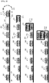
- FIG. 1 is a view schematically showing a general structure of a conventional representative stacked/folded type electrode assembly.
- an electrode assembly 100 includes a combination of unit cells 110, 130, 150, and 170, each of which is configured to have a structure in which a negative electrode 101, a separator 103, a positive electrode 102, another separator 103, and another negative electrode 101 are sequentially stacked, and unit cells 120, 140, 160, and 180, each of which is configured to have a structure in which a positive electrode 102, a separator 103, a negative electrode 101, another separator 103, and another positive electrode 102 are sequentially stacked.
- a separation film 190 which is interposed between the unit cells 110, 120, 130, 140, 150, 160, 170, and 180 of the electrode assembly 100, surrounds side surfaces of the unit cells 110, 120, 130, 140, 150, 160, 170, and 180 at which no electrode terminals are formed.
- the electrode assembly 100 is manufactured by winding the separation film 190 in the state in which the unit cells 110, 120, 130, 140, 150, 160, 170, and 180 are arranged on the separation film 190. Consequently, the electrode assembly 100 includes a total of 12 negative electrodes 101, a total of 12 positive electrodes 102, a total of 16 separators 103, and one separation film 190.
- the electrode assembly has a vertically asymmetrical structure, since electrodes having different polarities are located at opposite ends of the electrode assembly, i.e. the outermost electrodes of the electrode assembly are constituted by a positive electrode and a negative electrode.
- the electrode assembly has a vertically asymmetrical structure, the results of nail penetration tests at the opposite ends of the electrode assembly are different from each other, with the result that the safety of a battery cell including the electrode assembly may be reduced.
- active materials are applied to opposite surfaces of a current collector that constitutes each of the outermost electrodes of the electrode assembly.
- a conductive material such as a metallic material
- the active materials come into direct contact with the conductive material, with the result that a short circuit may occur in the battery cell, whereby the battery cell may catch fire or explode.
- a battery cell configured to have a structure in which the outermost electrodes of an electrode assembly are constituted by electrodes having the same polarity in the case in which an even number of unit cells are used, with the result that the electrode assembly can be inserted into a battery case irrespective of the direction in which the electrode assembly is inserted into a battery case, the external appearance of the electrode assembly is symmetrical, and the results of nail penetration tests at the opposite ends of the electrode assembly are the same.
- the present invention has been made to solve the above problems and other technical problems that have yet to be resolved.
- an electrode assembly including 2n unit cells e.g. four or more even-numbered unit cells
- an electrode assembly including 2n unit cells e.g. four or more even-numbered unit cells
- the outermost electrodes of the electrode assembly have the same polarity, with the result that it is not necessary to modify the structure of a battery case, into which the electrode assembly is inserted, depending on the direction in which the electrode assembly is inserted into the battery case, and the results of safety tests, such as nail penetration tests, at the opposite ends of the electrode assembly are the same, whereby it is possible to solve problems with the conventional art.
- the outermost electrodes of the electrode assembly are configured as single-sided electrodes, in each of which no electrode mixture is applied to the outer surface of a current collector facing the outside of the electrode assembly, with the result that it is possible to prevent the occurrence of a short circuit in the battery cell, thereby preventing spike current from flowing in the battery cell and preventing the battery cell from catching fire or exploding when external impact is applied to the battery cell, whereby it is possible to improve the safety of the battery cell.
- a stacked/folded type electrode assembly configured to have a structure in which a plurality of unit cells, each of which includes a positive electrode having an electrode mixture including an electrode active material applied to a current collector, a negative electrode having an electrode mixture including an electrode active material applied to a current collector, and a separator disposed between the positive electrode and the negative electrode, is wound in the state of being arranged on a sheet type separation film, wherein the unit cells include one full cell and three or more bi-cells, the outermost unit cells of the electrode assembly are each configured such that an electrode forming the outside of the electrode assembly is configured as a single-sided electrode, in which no electrode mixture is applied to the surface of the current collector facing the outside of the electrode assembly, and the single-sided electrodes are electrodes having the same polarity.
- the electrode assembly according to the present invention may include an even number of unit cells.
- a 2n-th unit cell or a (2n-1)-th unit cell located at a winding end point of the separation film, among the unit cells is configured as a full cell and the other unit cells are configured as A-type bi-cells and C-type bi-cells
- the electrode assembly completed by winding the separation film may be configured such that the outermost electrodes of the electrode assembly have the same polarity.
- a conventional electrode assembly which is configured to have an asymmetric structure in which the outermost electrodes of the electrode assembly have different polarities, i.e. the outermost electrodes of the electrode assembly are constituted by a positive electrode and a negative electrode, in that the results of nail penetration tests at the opposite ends of the electrode assembly are different from each other and in that design of the battery cell is difficult during the manufacture of the battery cell.
- the electrode assembly may include four or more even-numbered unit cells.
- the unit cells may be sequentially arranged on the separation film in a plane.
- the electrode assembly may include a total of 2n unit cells from a unit cell that is located at a winding start point of the separation film (i.e. a first unit cell) to a unit cell that is located at a winding end point of the separation film (i.e. a 2n-th unit cell (where n is an integer that satisfies 2 ⁇ n ⁇ 20)).
- the electrode assembly according to the present invention may include one full cell and three or more bi-cells as unit cells.
- the full cell is configured to have a structure in which electrodes having different polarities are located at opposite ends of the unit cell.
- the full cell may be a first full cell, which is configured to have a structure in which a first positive electrode, configured as a single-sided positive electrode, a separator, and a negative electrode are sequentially stacked, or a second full cell, which is configured to have a structure in which a first negative electrode, configured as a single-sided negative electrode, a separator, and a positive electrode are sequentially stacked.
- the first positive electrode or the first negative electrode may face the separation film.
- each of the bi-cells is configured to have a structure in which electrodes having the same polarity are located at opposite ends of the unit cell.
- Each of the bi-cells may be an A-type bi-cell, which is configured to have a structure in which a positive electrode, a negative electrode, and another positive electrode are sequentially stacked in the state in which separators are disposed therebetween, or a C-type bi-cell, which is configured to have a structure in which a negative electrode, a positive electrode, and another negative electrode are sequentially stacked in the state in which separators are disposed therebetween.
- the outermost electrodes constituting the unit cells located at the opposite ends of the electrode assembly, i.e. the outermost unit cells, among the bi-cells, i.e. the electrodes which form the outer surface of the electrode assembly, may be configured as single-sided electrodes, in each of which no electrode mixture is applied to the surface of a current collector facing the outside of the electrode assembly.
- the A-type bi-cell may include a 1A-type bi-cell, which is configured to have a structure in which a first positive electrode, configured as a single-sided positive electrode, a negative electrode, and a positive electrode are sequentially stacked in the state in which separators are disposed therebetween, or a 2A-type bi-cell, which is configured to have a structure in which a positive electrode, a negative electrode, and another positive electrode are sequentially stacked in the state in which separators are disposed therebetween.
- the C-type bi-cell may include a 1C-type bi-cell, which is configured to have a structure in which a first negative electrode, configured as a single-sided negative electrode, a positive electrode, and a negative electrode are sequentially stacked in the state in which separators are disposed therebetween, or a 2C-type bi-cell, which is configured to have a structure in which a negative electrode, a positive electrode, and another negative electrode are sequentially stacked in the state in which separators are disposed therebetween.
- a 1C-type bi-cell which is configured to have a structure in which a first negative electrode, configured as a single-sided negative electrode, a positive electrode, and a negative electrode are sequentially stacked in the state in which separators are disposed therebetween
- 2C-type bi-cell which is configured to have a structure in which a negative electrode, a positive electrode, and another negative electrode are sequentially stacked in the state in which separators are disposed therebetween.
- the first unit cell which is located at the winding start point of the separation film, may be configured as any one selected from between an A-type bi-cell and a C-type bi-cell.
- one of the outermost unit cells of the electrode assembly may be a full cell and the other of the outermost unit cells of the electrode assembly may be a bi-cell such that the electrode assembly is configured to have a symmetric structure in which the outermost electrodes have the same polarity.
- the 2n-th unit cell which is one of the outermost unit cells of the electrode assembly, is a bi-cell and the (2n-1)-th unit cell, which is the other of the outermost unit cells of the electrode assembly, is a full cell
- the 2n-th unit cell may be configured as a 1A-type bi-cell
- the (2n-1)-th unit cell may be configured as a first full cell
- the 2n-th unit cell may be configured as a 1C-type bi-cell
- the (2n-1)-th unit cell may be configured as a second full cell.
- the 2n-th unit cell which is one of the outermost unit cells of the electrode assembly, is a full cell and the (2n-1)-th unit cell, which is the other of the outermost unit cells of the electrode assembly, is a bi-cell
- the 2n-th unit cell may be configured as a first full cell
- the (2n-1)-th unit cell may be configured as a 1A-type bi-cell
- the 2n-th unit cell may be configured as a second full cell
- the (2n-1)-th unit cell may be configured as a 1C-type bi-cell.
- the outermost electrodes may have the same polarity.
- the outermost electrodes may be configured as single-sided electrodes, in each of which no electrode mixture is applied to the outer surface of a current collector facing the outside of the electrode assembly.
- Each of the outermost electrodes of the outermost unit cells may be configured as a first positive electrode or a first negative electrode.
- a battery cell according to the present invention may be manufactured by placing the electrode assembly with the above-stated construction in a battery case.
- the battery case may be configured to have a structure including a cylindrical or prismatic container and a cap mounted to the open upper end of the container.
- the present invention is not limited thereto.
- the battery case may be a pouch-shaped case made of a laminate sheet including a resin layer and a metal layer.
- the kind of battery cell according to the present invention is not particularly restricted.
- the battery cell according to the present invention may be a lithium secondary battery, such as a lithium ion battery or a lithium ion polymer battery, which exhibits high energy density, discharge voltage, and output stability.
- a battery pack including the secondary battery according to the present invention as a unit cell.
- the battery pack may be constituted by a battery cell used as a power source for a small-sized device.
- the battery pack may be constituted by a middle or large-sized battery module including a plurality of battery cells used as a power source for a middle or large-sized device requiring the ability to withstand high temperature, a long cycle, high rate characteristics, etc.
- the device may be any one selected from among a mobile electronic device, a power tool driven by a battery-powered motor, an electric automobile, such as such as an electric vehicle (EV), a hybrid electric vehicle (HEV), or a plug-in hybrid electric vehicle (PHEV), an electric two-wheeled vehicle, such as an electric bicycle (E-bike) or an electric scooter (E-scooter), an electric golf cart, and a power storage system.
- a mobile electronic device such as such as an electric vehicle (EV), a hybrid electric vehicle (HEV), or a plug-in hybrid electric vehicle (PHEV), an electric two-wheeled vehicle, such as an electric bicycle (E-bike) or an electric scooter (E-scooter), an electric golf cart, and a power storage system.
- a mobile electronic device such as such as an electric vehicle (EV), a hybrid electric vehicle (HEV), or a plug-in hybrid electric vehicle (PHEV), an electric two-wheeled vehicle, such as an electric bicycle (E-bike) or an electric scooter (E-scoo
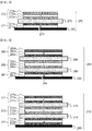
- FIG. 2 is a view schematically showing the structure of an electrode assembly according to an embodiment of the present invention
- FIG. 3 is a view schematically showing the state in which four kinds of unit cells are placed on a separation film in order to manufacture the electrode assembly of FIG. 2 .
- an electrode assembly 200 is manufactured by arranging unit cells 210, 220, 230, 240, 250, 260, and 280, the outermost electrodes of each of which have the same polarity, and a unit cell 270, the outermost electrodes of which have different polarities, on a separation film 290 such that different electrodes are adjacent to each other in the state in which the separation film 290 is wound and then winding the separation film 290.
- the unit cells 210, 220, 230, 240, 250, 260, 270, and 280 are sequentially arranged in the same plane from the first unit cell 210, which is located at the winding start point of the separation film 290, to the eighth unit cell 280, which is located at the winding end point of the separation film 290.
- the seventh unit cell 270 which is a full cell, faces the separation film 290 in the state in which a positive electrode 271 of the seventh unit cell 270 is located under the separation film 290.
- the positive electrode 271 of the seventh unit cell 270 which constitutes one of the outermost electrodes of the electrode assembly 200, is a single-sided positive electrode configured such that an active material layer is applied only to one major surface of a positive electrode current collector facing a separator 275 and such that no active material layer is applied to the other major surface of the positive electrode current collector facing the separation film 290.
- a positive electrode 281 of the eighth unit cell 280 which constitutes the other of the outermost electrodes of the electrode assembly 200, is a single-sided positive electrode, configured such that an active material layer is applied only to one major surface of a positive electrode current collector facing a separator 285 and such that no active material layer is applied to the other major surface of the positive electrode current collector facing the separation film 290.
- the electrode assembly 200 is manufactured by winding the separation film 290 from the first unit cell 210 to the eighth unit cell 280 in the counterclockwise direction 292 such that the first unit cell 210 is located in the middle portion of the electrode assembly 200.
- the first unit cell 210 is placed in a region 291 defined between the first unit cell 210 and the second unit cell 220 in the state of being turned upside down. Subsequently, the separation film 290 is wound such that a positive electrode 211 of the first unit cell 210, which has been first located at the lower side of the first unit cell 210, faces a negative electrode 222 of the second unit cell 220, which is located at the upper side of the second unit cell 220, in the state in which the separation film 290 is disposed between the first unit cell 210 and the second unit cell 220.
- first unit cell 210 and the second unit cell 220 which face each other in the state in which the separation film 290 is disposed between the first unit cell 210 and the second unit cell 220, are simultaneously wound in the state of being arranged on the separation film 290.
- a positive electrode 213 of the first unit cell 210 which has been located at the upper side of the first unit cell 210, faces a negative electrode 232 of the third unit cell 230, which is located at the upper side of the third unit cell 230, in the state in which the separation film 290 is disposed between the first unit cell 210 and the third unit cell 230.
- the electrode assembly 200 is completed such that the electrode assembly 200 is configured to have a structure in which the first unit cell 210 is located in the middle portion of the electrode assembly 200 and in which the seventh unit cell 270 and the eighth unit cell 280 are located at the opposite ends of the electrode assembly 200.
- FIGS. 4 to 6 are views schematically showing the structures of unit cells that constitute the electrode assembly according to the embodiment of the present invention.
- FIG. 4 is a view schematically showing a full cell that constitutes the electrode assembly according to the present invention.
- the unit cell 270 which is one of the outermost unit cells of the electrode assembly, is a full cell, which is configured to have a structure in which electrodes having different polarities are located at opposite ends of the unit cell.
- the full cell 270 is a first full cell, configured to have a structure in which a first positive electrode 271, which is a single-sided positive electrode, a separator 275, and a negative electrode 272 are sequentially stacked.
- the first positive electrode 271 faces the separation film 290.
- the first positive electrode 271 is a single-sided positive electrode configured such that a positive electrode mixture 271b is applied to one major surface of a positive electrode current collector 271a that faces the separator 275 and such that the positive electrode mixture 271b is not applied to the other major surface 274 of the positive electrode current collector 271a that faces the outside of the electrode assembly.
- the negative electrode 272 is a double-sided negative electrode configured such that negative electrode active materials 272b and 272c are applied to opposite major surfaces of a negative electrode current collector 272a.
- FIGS. 5 and 6 are views schematically showing bi-cells that constitute the electrode assembly according to the present invention.
- each of the bi-cells is configured to have a structure in which electrodes having the same polarity are located at opposite ends of the unit cell.
- the bi-cells shown in FIG. 5 are A-type bi-cells, each of which is configured to have a structure in which a positive electrode, a separator, a negative electrode, another separator, and another positive electrode are sequentially stacked
- the bi-cell shown in FIG. 6 is an C-type bi-cell, which configured to have a structure in which a negative electrode, a separator, a positive electrode, another separator, and another negative electrode are sequentially stacked.
- a 1A-type bi-cell 280 which is one of the A-type bi-cells shown in FIG. 5 , which is one of the outermost unit cells of the electrode assembly and has a single-sided electrode 281, is configured to have a structure in which a first positive electrode 281, which is a single-sided positive electrode, a negative electrode 282, and a positive electrode 283 are sequentially stacked in the state in which separators 285 are disposed therebetween.
- a 2A-type bi-cell 210 which is the other of the A-type bi-cells shown in FIG.
- the electrode 5 which is located in the middle portion of the electrode assembly, is configured to have a structure in which a positive electrode 211, a negative electrode 212, and another positive electrode 211 are sequentially stacked in the state in which separators 215 are disposed therebetween.
- the first positive electrode 281 is a single-sided positive electrode configured such that a positive electrode mixture 281b is applied to one major surface of a positive electrode current collector 281a that faces the separator 285 and such that the positive electrode mixture 281b is not applied to the other major surface 284 of the positive electrode current collector 281a that faces the outside of the electrode assembly.
- the positive electrode 211 is a double-sided positive electrode configured such that positive electrode active materials 211b are 211c are applied to opposite major surfaces of a positive electrode current collector 211a
- the positive electrode 283 is a double-sided positive electrode configured such that positive electrode active materials 283b and 283c are applied to opposite major surfaces of a positive electrode current collector 283a.
- the negative electrode 212 is a double-sided negative electrode, configured such that negative electrode active materials 212b are 212c are applied to opposite major surfaces of a negative electrode current collector 212a
- the negative electrode 282 is a double-sided negative electrode, configured such that negative electrode active materials 282b and 282c are applied to opposite major surfaces of a negative electrode current collector 282a.
- the C-type bi-cell shown in FIG. 6 which is referred to as a 2C-type bi-cell 220, is configured to have a structure in which a negative electrode 222, a positive electrode 221, and another negative electrode 222 are sequentially stacked in the state in which separators 225 are disposed therebetween.
- the positive electrode 221 is a double-sided positive electrode configured such that positive electrode active materials 221b are 221c are applied to opposite major surfaces of a positive electrode current collector 221a
- the negative electrode 222 is a double-sided negative electrode configured such that negative electrode active materials 222b are 222c are applied to opposite major surfaces of a negative electrode current collector 222a.
- one selected from between the seventh unit cell 270 and the eighth unit cell 280 is configured as a pull-cell and the other selected from between the seventh unit cell 270 and the eighth unit cell 280 is configured as a bi-cell such that the outermost electrodes of the electrode assembly have the same polarity in the state in which the electrode assembly is wound.
- the first unit cell 210 may be configured as a bi-cell
- the seventh unit cell 270 may be configured as a pull-cell.
- the seventh unit cell 270 is configured as a first pull-cell when the eighth unit cell 280 is configured as a 1A-type bi-cell, and the seventh unit cell 270 is configured as a second pull-cell when the eighth unit cell 280 is configured as a 1C-type bi-cell.
- each of the outermost electrodes 271 and 281 of the electrode assembly 200 is constituted by a first positive electrode, which is configured as a single-sided electrode, or a second negative electrode, which is configured as a single-sided electrode. Consequently, the outermost electrodes of the electrode assembly have the same polarity.
- FIG. 7 is a view schematically showing the structure of an electrode assembly manufactured in the state of being arranged in order that is different from the order shown in FIG. 5 .
- a first unit cell 410 is configured as a bi-cell and an eighth unit cell 480 is configured as a full cell.
- the eighth unit cell 480 is configured as a second full cell
- a seventh unit cell 470 is configured as a 1C-type bi-cell. Consequently, the outermost electrodes, i.e. electrodes 471 and 482, of the electrode assembly have the same polarity.
- FIG. 8 is a view schematically showing a full cell that constitutes the electrode assembly of FIG. 7 .
- the unit cell 480 which is one of the outermost electrodes of the electrode assembly, is a full cell configured to have a structure in which electrodes having different polarities are located at opposite ends of the unit cell.
- the full cell 480 is a second full cell, which is configured to have a structure in which a first negative electrode 482, which is a single-sided negative electrode, a separator 485, and a positive electrode 481 are sequentially stacked.
- the first negative electrode 482 faces the separation film 290.
- the first negative electrode 482 is a single-sided negative electrode configured such that a negative electrode mixture 482b is applied to one major surface of a negative electrode current collector 482a that faces the separator 485 and such that the negative electrode mixture 482b is not applied to the other major surface 484 of the negative electrode current collector 482a that faces the outside of the electrode assembly.
- the positive electrode 481 is a double-sided positive electrode configured such that positive electrode active materials 481b are 481c are applied to opposite major surfaces of a positive electrode current collector 481a.
- FIG. 9 is a view schematically showing a bi-cell that constitutes the electrode assembly of FIG. 7 .
- the bi-cell is configured to have a structure in which electrodes having the same polarity are located at opposite ends of the unit cell.
- the bi-cell shown in FIG. 9 is a C-type bi-cell, configured such that a negative electrode, a separator, a positive electrode, another separator, and another negative electrode are sequentially stacked.
- the C-type bi-cell shown in FIG. 9 which is referred to as a 1C-type bi-cell 470, which is one of the outermost unit cells of the electrode assembly and has a single-sided electrode 472, is configured to have a structure in which a first negative electrode 472, which is a single-sided negative electrode, a positive electrode 471, and a negative electrode 476 are sequentially stacked in the state in which separators 475 are disposed therebetween.
- the first negative electrode 472 is a single-sided negative electrode configured such that a negative electrode mixture 472b is applied to one major surface of a negative electrode current collector 472a that faces the separator 475 and such that the negative electrode mixture 472b is not applied to the other major surface 474 of the negative electrode current collector 472a that faces the outside of the electrode assembly.
- the positive electrode 471 is a double-sided positive electrode configured such that positive electrode active materials 471b are 471c are applied to opposite major surfaces of a positive electrode current collector 471a.
- the negative electrode 476 is a double-sided negative electrode configured such that negative electrode active materials 476b and 476c are applied to opposite major surfaces of a negative electrode current collector 476a.
- the first unit cell 410 is configured as a bi-cell and the eighth unit cell 480 is configured as a full cell such that the outermost electrodes of the electrode assembly have the same polarity in the state in which the electrode assembly is wound.
- the eighth unit cell 480 is configured as a first full cell
- the seventh unit cell 470 is configured as a 1A-type bi-cell.
- the seventh unit cell 470 is configured as a 1C-type bi-cell.
- each of the outermost electrodes 471 and 472 of the electrode assembly 400 is constituted by a first negative electrode, which is configured as a single-sided electrode, or a second positive electrode, which is configured as a single-sided electrode. Consequently, the outermost electrodes of the electrode assembly have the same polarity.
- the electrode assembly is configured to have a symmetrical structure, as described above, it is not necessary to modify the structure of the battery case, into which the electrode assembly is inserted, depending on the direction in which the electrode assembly is inserted into the battery case.
- the outermost electrodes of the electrode assembly are configured as single-sided electrodes. Consequently, it is possible to prevent the occurrence of a short circuit in the battery cell, thereby preventing spike current from flowing in the battery cell and preventing the battery cell from catching fire when external impact is applied to the battery cell, whereby it is possible to improve the safety of the battery cell.
- a battery cell according to the present invention includes an electrode assembly including 2n unit cells, e.g. four or more even-numbered unit cells, wherein a 2n-th unit cell or a (2n-1)-th unit cell located at a winding end point of a separation film is configured as a full cell, whereby the outermost electrodes of the electrode assembly have the same polarity. Consequently, it is not necessary to modify the structure of a battery case, into which the electrode assembly is inserted, depending on the direction in which the electrode assembly is inserted into the battery case. In addition, the results of safety tests, such as nail penetration tests, at the opposite ends of the electrode assembly are the same. Consequently, it is possible to solve difficulty in the design of the battery cell, which is caused during the manufacture of the battery cell.
- the outermost electrodes of the electrode assembly are configured as single-sided electrodes, in each of which no electrode mixture is applied to the outer surface of a current collector facing the outside of the electrode assembly. Consequently, it is possible to prevent the occurrence of a short circuit in the battery cell, thereby preventing spike current from flowing in the battery cell and preventing the battery cell from catching fire or exploding when external impact is applied to the battery cell, for example at the time of nail penetration tests, whereby it is possible to improve the safety of the battery cell.
Applications Claiming Priority (2)
| Application Number | Priority Date | Filing Date | Title |
|---|---|---|---|
| KR1020140150096A KR101791674B1 (ko) | 2014-10-31 | 2014-10-31 | 바이셀과 풀셀을 포함하는 전극조립체 및 이를 포함하는 이차전지 |
| PCT/KR2015/011188 WO2016068544A1 (ko) | 2014-10-31 | 2015-10-22 | 바이셀과 풀셀을 포함하는 전극조립체 및 이를 포함하는 이차전지 |
Publications (3)
| Publication Number | Publication Date |
|---|---|
| EP3174152A1 true EP3174152A1 (de) | 2017-05-31 |
| EP3174152A4 EP3174152A4 (de) | 2017-06-28 |
| EP3174152B1 EP3174152B1 (de) | 2018-08-29 |
Family
ID=55857806
Family Applications (1)
| Application Number | Title | Priority Date | Filing Date |
|---|---|---|---|
| EP15855712.4A Active EP3174152B1 (de) | 2014-10-31 | 2015-10-22 | Elektrodenaggregat mit bi-zellen und brennstoffzelle sowie sekundärbatterie damit |
Country Status (5)
| Country | Link |
|---|---|
| US (1) | US10454132B2 (de) |
| EP (1) | EP3174152B1 (de) |
| KR (1) | KR101791674B1 (de) |
| CN (1) | CN107004889B (de) |
| WO (1) | WO2016068544A1 (de) |
Families Citing this family (4)
| Publication number | Priority date | Publication date | Assignee | Title |
|---|---|---|---|---|
| KR102197360B1 (ko) * | 2017-01-04 | 2020-12-31 | 주식회사 엘지화학 | 향상된 기계적 강도의 단면 전극을 포함하고 있는 전극조립체 |
| KR102217447B1 (ko) * | 2017-07-06 | 2021-02-22 | 주식회사 엘지화학 | 이차전지 |
| CN107181005B (zh) * | 2017-07-11 | 2018-10-12 | 力信(江苏)能源科技有限责任公司 | 一种卷绕-卷叠式电池 |
| KR102311950B1 (ko) * | 2018-11-19 | 2021-10-14 | 주식회사 엘지에너지솔루션 | 전극조립체 |
Family Cites Families (7)
| Publication number | Priority date | Publication date | Assignee | Title |
|---|---|---|---|---|
| KR100497147B1 (ko) | 2000-02-08 | 2005-06-29 | 주식회사 엘지화학 | 다중 중첩 전기화학 셀 및 그의 제조방법 |
| KR100987300B1 (ko) | 2007-07-04 | 2010-10-12 | 주식회사 엘지화학 | 스택-폴딩형 전극조립체 및 그것의 제조방법 |
| KR101014817B1 (ko) * | 2007-12-14 | 2011-02-14 | 주식회사 엘지화학 | 안전 부재를 포함하고 있는 스택/폴딩형 전극조립체 및그것의 제조방법 |
| US20100304198A1 (en) | 2009-05-28 | 2010-12-02 | Samsung Sdi Co., Ltd. | Electrode assembly for secondary battery and method of manufacturing the same |
| KR101345349B1 (ko) | 2010-08-25 | 2013-12-27 | 주식회사 엘지화학 | 신규한 구조의 전극조립체 |
| KR101553542B1 (ko) | 2012-09-14 | 2015-09-16 | 에스케이이노베이션 주식회사 | 2차 전지 내부 셀 스택 방법 및 이를 이용하여 제조되는 셀 스택 |
| KR101567629B1 (ko) * | 2012-11-12 | 2015-11-10 | 주식회사 엘지화학 | 상하 대칭 구조를 갖는 전극 조립체, 상기 전극 조립체를 포함하는 이차 전지, 전지팩 및 디바이스 |
-
2014
- 2014-10-31 KR KR1020140150096A patent/KR101791674B1/ko active IP Right Grant
-
2015
- 2015-10-22 WO PCT/KR2015/011188 patent/WO2016068544A1/ko active Application Filing
- 2015-10-22 CN CN201580044912.1A patent/CN107004889B/zh active Active
- 2015-10-22 US US15/505,512 patent/US10454132B2/en active Active
- 2015-10-22 EP EP15855712.4A patent/EP3174152B1/de active Active
Also Published As
| Publication number | Publication date |
|---|---|
| EP3174152A4 (de) | 2017-06-28 |
| CN107004889A (zh) | 2017-08-01 |
| CN107004889B (zh) | 2020-07-31 |
| US10454132B2 (en) | 2019-10-22 |
| KR20160050920A (ko) | 2016-05-11 |
| KR101791674B1 (ko) | 2017-10-30 |
| WO2016068544A1 (ko) | 2016-05-06 |
| EP3174152B1 (de) | 2018-08-29 |
| US20170207481A1 (en) | 2017-07-20 |
Similar Documents
| Publication | Publication Date | Title |
|---|---|---|
| JP6453515B1 (ja) | 積層式二次電池の製造方法 | |
| US10115996B2 (en) | Stepped electrode assembly, secondary battery including the electrode assembly, and method of manufacturing the electrode assembly | |
| EP2802034A1 (de) | Elektrodenanordnung mit stufenförmiger struktur und zusammengesetzte elektrodenanordnung | |
| US9871241B2 (en) | Electrode assembly having excellent degree of freedom in shape thereof in thickness direction, secondary cell battery, battery pack, and device including electrode assembly | |
| EP3174152B1 (de) | Elektrodenaggregat mit bi-zellen und brennstoffzelle sowie sekundärbatterie damit | |
| EP2919312B1 (de) | Batteriezelle mit einer elektrodenanordnung mit wechselnder ausrichtungsstruktur | |
| US9325032B2 (en) | Electrode assembly, battery and device including the same | |
| US9935329B2 (en) | Stepped electrode group stack | |
| US20140186685A1 (en) | Electrode assembly of stair-like structure | |
| EP2940776A1 (de) | Elektrodenanordnung mit stufenförmiger struktur | |
| EP3168918B1 (de) | In beide richtungen gewundene elektrodenanordnung und lithiumsekundärbatterie damit | |
| KR20160007109A (ko) | 전극 조립체의 복수개의 전극 탭과 전극 리드의 연결부의 포밍 방법 및 이를 이용하여 제조된 이차 전지 | |
| KR101888207B1 (ko) | 전지 셀 적층 지그 | |
| EP2933865B1 (de) | Laminat aus elektrodengruppen mit stufenförmiger struktur | |
| KR102630997B1 (ko) | 이차전지 | |
| KR102057114B1 (ko) | 예비 절단선이 형성된 파우치형 이차전지 | |
| EP3159959B1 (de) | Batteriezelle mit batteriegehäuse mit geformtem projektionsteil darauf entsprechend einer stufenartig strukturierten elektrodenanordnung | |
| KR102108208B1 (ko) | 원형 전극을 포함하는 원통형 이차전지 | |
| KR102072970B1 (ko) | 지그재그 형태의 전극조립체를 포함하는 전지셀 | |
| KR101684359B1 (ko) | 수직 적층 구조의 전지셀 | |
| US11189884B2 (en) | Cell and battery | |
| KR200262458Y1 (ko) | 이차전지 전극구조물 | |
| US20140255756A1 (en) | Stepped Electrode Group Stack | |
| KR102069513B1 (ko) | 파열 예정부를 포함하는 이차전지 및 이의 제조 방법 |
Legal Events
| Date | Code | Title | Description |
|---|---|---|---|
| PUAI | Public reference made under article 153(3) epc to a published international application that has entered the european phase |
Free format text: ORIGINAL CODE: 0009012 |
|
| 17P | Request for examination filed |
Effective date: 20170221 |
|
| AK | Designated contracting states |
Kind code of ref document: A1 Designated state(s): AL AT BE BG CH CY CZ DE DK EE ES FI FR GB GR HR HU IE IS IT LI LT LU LV MC MK MT NL NO PL PT RO RS SE SI SK SM TR |
|
| AX | Request for extension of the european patent |
Extension state: BA ME |
|
| RIC1 | Information provided on ipc code assigned before grant |
Ipc: H01M 10/04 20060101AFI20170518BHEP Ipc: H01M 10/0585 20100101ALN20170518BHEP Ipc: H01M 10/058 20100101ALI20170518BHEP |
|
| A4 | Supplementary search report drawn up and despatched |
Effective date: 20170529 |
|
| DAV | Request for validation of the european patent (deleted) | ||
| DAX | Request for extension of the european patent (deleted) | ||
| RIC1 | Information provided on ipc code assigned before grant |
Ipc: H01M 10/058 20100101ALI20180328BHEP Ipc: H01M 10/0525 20100101ALN20180328BHEP Ipc: H01M 10/04 20060101AFI20180328BHEP Ipc: H01M 10/0585 20100101ALN20180328BHEP |
|
| GRAP | Despatch of communication of intention to grant a patent |
Free format text: ORIGINAL CODE: EPIDOSNIGR1 |
|
| INTG | Intention to grant announced |
Effective date: 20180515 |
|
| GRAS | Grant fee paid |
Free format text: ORIGINAL CODE: EPIDOSNIGR3 |
|
| GRAJ | Information related to disapproval of communication of intention to grant by the applicant or resumption of examination proceedings by the epo deleted |
Free format text: ORIGINAL CODE: EPIDOSDIGR1 |
|
| GRAL | Information related to payment of fee for publishing/printing deleted |
Free format text: ORIGINAL CODE: EPIDOSDIGR3 |
|
| GRAR | Information related to intention to grant a patent recorded |
Free format text: ORIGINAL CODE: EPIDOSNIGR71 |
|
| GRAA | (expected) grant |
Free format text: ORIGINAL CODE: 0009210 |
|
| INTC | Intention to grant announced (deleted) | ||
| RIC1 | Information provided on ipc code assigned before grant |
Ipc: H01M 10/04 20060101AFI20180703BHEP Ipc: H01M 10/058 20100101ALI20180703BHEP Ipc: H01M 10/0525 20100101ALN20180703BHEP Ipc: H01M 10/0585 20100101ALN20180703BHEP |
|
| INTG | Intention to grant announced |
Effective date: 20180717 |
|
| AK | Designated contracting states |
Kind code of ref document: B1 Designated state(s): AL AT BE BG CH CY CZ DE DK EE ES FI FR GB GR HR HU IE IS IT LI LT LU LV MC MK MT NL NO PL PT RO RS SE SI SK SM TR |
|
| REG | Reference to a national code |
Ref country code: GB Ref legal event code: FG4D |
|
| REG | Reference to a national code |
Ref country code: CH Ref legal event code: EP |
|
| REG | Reference to a national code |
Ref country code: AT Ref legal event code: REF Ref document number: 1036226 Country of ref document: AT Kind code of ref document: T Effective date: 20180915 |
|
| REG | Reference to a national code |
Ref country code: IE Ref legal event code: FG4D |
|
| REG | Reference to a national code |
Ref country code: DE Ref legal event code: R096 Ref document number: 602015015790 Country of ref document: DE |
|
| REG | Reference to a national code |
Ref country code: FR Ref legal event code: PLFP Year of fee payment: 4 |
|
| REG | Reference to a national code |
Ref country code: NL Ref legal event code: MP Effective date: 20180829 |
|
| REG | Reference to a national code |
Ref country code: LT Ref legal event code: MG4D |
|
| PG25 | Lapsed in a contracting state [announced via postgrant information from national office to epo] |
Ref country code: BG Free format text: LAPSE BECAUSE OF FAILURE TO SUBMIT A TRANSLATION OF THE DESCRIPTION OR TO PAY THE FEE WITHIN THE PRESCRIBED TIME-LIMIT Effective date: 20181129 Ref country code: SE Free format text: LAPSE BECAUSE OF FAILURE TO SUBMIT A TRANSLATION OF THE DESCRIPTION OR TO PAY THE FEE WITHIN THE PRESCRIBED TIME-LIMIT Effective date: 20180829 Ref country code: GR Free format text: LAPSE BECAUSE OF FAILURE TO SUBMIT A TRANSLATION OF THE DESCRIPTION OR TO PAY THE FEE WITHIN THE PRESCRIBED TIME-LIMIT Effective date: 20181130 Ref country code: FI Free format text: LAPSE BECAUSE OF FAILURE TO SUBMIT A TRANSLATION OF THE DESCRIPTION OR TO PAY THE FEE WITHIN THE PRESCRIBED TIME-LIMIT Effective date: 20180829 Ref country code: LT Free format text: LAPSE BECAUSE OF FAILURE TO SUBMIT A TRANSLATION OF THE DESCRIPTION OR TO PAY THE FEE WITHIN THE PRESCRIBED TIME-LIMIT Effective date: 20180829 Ref country code: NL Free format text: LAPSE BECAUSE OF FAILURE TO SUBMIT A TRANSLATION OF THE DESCRIPTION OR TO PAY THE FEE WITHIN THE PRESCRIBED TIME-LIMIT Effective date: 20180829 Ref country code: RS Free format text: LAPSE BECAUSE OF FAILURE TO SUBMIT A TRANSLATION OF THE DESCRIPTION OR TO PAY THE FEE WITHIN THE PRESCRIBED TIME-LIMIT Effective date: 20180829 Ref country code: NO Free format text: LAPSE BECAUSE OF FAILURE TO SUBMIT A TRANSLATION OF THE DESCRIPTION OR TO PAY THE FEE WITHIN THE PRESCRIBED TIME-LIMIT Effective date: 20181129 Ref country code: IS Free format text: LAPSE BECAUSE OF FAILURE TO SUBMIT A TRANSLATION OF THE DESCRIPTION OR TO PAY THE FEE WITHIN THE PRESCRIBED TIME-LIMIT Effective date: 20181229 |
|
| REG | Reference to a national code |
Ref country code: AT Ref legal event code: MK05 Ref document number: 1036226 Country of ref document: AT Kind code of ref document: T Effective date: 20180829 |
|
| PG25 | Lapsed in a contracting state [announced via postgrant information from national office to epo] |
Ref country code: AL Free format text: LAPSE BECAUSE OF FAILURE TO SUBMIT A TRANSLATION OF THE DESCRIPTION OR TO PAY THE FEE WITHIN THE PRESCRIBED TIME-LIMIT Effective date: 20180829 Ref country code: HR Free format text: LAPSE BECAUSE OF FAILURE TO SUBMIT A TRANSLATION OF THE DESCRIPTION OR TO PAY THE FEE WITHIN THE PRESCRIBED TIME-LIMIT Effective date: 20180829 Ref country code: LV Free format text: LAPSE BECAUSE OF FAILURE TO SUBMIT A TRANSLATION OF THE DESCRIPTION OR TO PAY THE FEE WITHIN THE PRESCRIBED TIME-LIMIT Effective date: 20180829 |
|
| PG25 | Lapsed in a contracting state [announced via postgrant information from national office to epo] |
Ref country code: PL Free format text: LAPSE BECAUSE OF FAILURE TO SUBMIT A TRANSLATION OF THE DESCRIPTION OR TO PAY THE FEE WITHIN THE PRESCRIBED TIME-LIMIT Effective date: 20180829 Ref country code: EE Free format text: LAPSE BECAUSE OF FAILURE TO SUBMIT A TRANSLATION OF THE DESCRIPTION OR TO PAY THE FEE WITHIN THE PRESCRIBED TIME-LIMIT Effective date: 20180829 Ref country code: IT Free format text: LAPSE BECAUSE OF FAILURE TO SUBMIT A TRANSLATION OF THE DESCRIPTION OR TO PAY THE FEE WITHIN THE PRESCRIBED TIME-LIMIT Effective date: 20180829 Ref country code: RO Free format text: LAPSE BECAUSE OF FAILURE TO SUBMIT A TRANSLATION OF THE DESCRIPTION OR TO PAY THE FEE WITHIN THE PRESCRIBED TIME-LIMIT Effective date: 20180829 Ref country code: AT Free format text: LAPSE BECAUSE OF FAILURE TO SUBMIT A TRANSLATION OF THE DESCRIPTION OR TO PAY THE FEE WITHIN THE PRESCRIBED TIME-LIMIT Effective date: 20180829 Ref country code: CZ Free format text: LAPSE BECAUSE OF FAILURE TO SUBMIT A TRANSLATION OF THE DESCRIPTION OR TO PAY THE FEE WITHIN THE PRESCRIBED TIME-LIMIT Effective date: 20180829 Ref country code: ES Free format text: LAPSE BECAUSE OF FAILURE TO SUBMIT A TRANSLATION OF THE DESCRIPTION OR TO PAY THE FEE WITHIN THE PRESCRIBED TIME-LIMIT Effective date: 20180829 |
|
| PG25 | Lapsed in a contracting state [announced via postgrant information from national office to epo] |
Ref country code: SK Free format text: LAPSE BECAUSE OF FAILURE TO SUBMIT A TRANSLATION OF THE DESCRIPTION OR TO PAY THE FEE WITHIN THE PRESCRIBED TIME-LIMIT Effective date: 20180829 Ref country code: DK Free format text: LAPSE BECAUSE OF FAILURE TO SUBMIT A TRANSLATION OF THE DESCRIPTION OR TO PAY THE FEE WITHIN THE PRESCRIBED TIME-LIMIT Effective date: 20180829 Ref country code: SM Free format text: LAPSE BECAUSE OF FAILURE TO SUBMIT A TRANSLATION OF THE DESCRIPTION OR TO PAY THE FEE WITHIN THE PRESCRIBED TIME-LIMIT Effective date: 20180829 |
|
| REG | Reference to a national code |
Ref country code: CH Ref legal event code: PL Ref country code: DE Ref legal event code: R097 Ref document number: 602015015790 Country of ref document: DE |
|
| REG | Reference to a national code |
Ref country code: BE Ref legal event code: MM Effective date: 20181031 |
|
| PG25 | Lapsed in a contracting state [announced via postgrant information from national office to epo] |
Ref country code: MC Free format text: LAPSE BECAUSE OF FAILURE TO SUBMIT A TRANSLATION OF THE DESCRIPTION OR TO PAY THE FEE WITHIN THE PRESCRIBED TIME-LIMIT Effective date: 20180829 Ref country code: LU Free format text: LAPSE BECAUSE OF NON-PAYMENT OF DUE FEES Effective date: 20181022 |
|
| PLBE | No opposition filed within time limit |
Free format text: ORIGINAL CODE: 0009261 |
|
| STAA | Information on the status of an ep patent application or granted ep patent |
Free format text: STATUS: NO OPPOSITION FILED WITHIN TIME LIMIT |
|
| REG | Reference to a national code |
Ref country code: IE Ref legal event code: MM4A |
|
| 26N | No opposition filed |
Effective date: 20190531 |
|
| PG25 | Lapsed in a contracting state [announced via postgrant information from national office to epo] |
Ref country code: SI Free format text: LAPSE BECAUSE OF FAILURE TO SUBMIT A TRANSLATION OF THE DESCRIPTION OR TO PAY THE FEE WITHIN THE PRESCRIBED TIME-LIMIT Effective date: 20180829 Ref country code: BE Free format text: LAPSE BECAUSE OF NON-PAYMENT OF DUE FEES Effective date: 20181031 Ref country code: CH Free format text: LAPSE BECAUSE OF NON-PAYMENT OF DUE FEES Effective date: 20181031 Ref country code: LI Free format text: LAPSE BECAUSE OF NON-PAYMENT OF DUE FEES Effective date: 20181031 |
|
| PG25 | Lapsed in a contracting state [announced via postgrant information from national office to epo] |
Ref country code: IE Free format text: LAPSE BECAUSE OF NON-PAYMENT OF DUE FEES Effective date: 20181022 |
|
| PG25 | Lapsed in a contracting state [announced via postgrant information from national office to epo] |
Ref country code: MT Free format text: LAPSE BECAUSE OF NON-PAYMENT OF DUE FEES Effective date: 20181022 |
|
| PG25 | Lapsed in a contracting state [announced via postgrant information from national office to epo] |
Ref country code: TR Free format text: LAPSE BECAUSE OF FAILURE TO SUBMIT A TRANSLATION OF THE DESCRIPTION OR TO PAY THE FEE WITHIN THE PRESCRIBED TIME-LIMIT Effective date: 20180829 |
|
| PG25 | Lapsed in a contracting state [announced via postgrant information from national office to epo] |
Ref country code: PT Free format text: LAPSE BECAUSE OF FAILURE TO SUBMIT A TRANSLATION OF THE DESCRIPTION OR TO PAY THE FEE WITHIN THE PRESCRIBED TIME-LIMIT Effective date: 20180829 |
|
| PG25 | Lapsed in a contracting state [announced via postgrant information from national office to epo] |
Ref country code: HU Free format text: LAPSE BECAUSE OF FAILURE TO SUBMIT A TRANSLATION OF THE DESCRIPTION OR TO PAY THE FEE WITHIN THE PRESCRIBED TIME-LIMIT; INVALID AB INITIO Effective date: 20151022 Ref country code: MK Free format text: LAPSE BECAUSE OF NON-PAYMENT OF DUE FEES Effective date: 20180829 Ref country code: CY Free format text: LAPSE BECAUSE OF FAILURE TO SUBMIT A TRANSLATION OF THE DESCRIPTION OR TO PAY THE FEE WITHIN THE PRESCRIBED TIME-LIMIT Effective date: 20180829 |
|
| P01 | Opt-out of the competence of the unified patent court (upc) registered |
Effective date: 20230512 |
|
| REG | Reference to a national code |
Ref country code: DE Ref legal event code: R081 Ref document number: 602015015790 Country of ref document: DE Owner name: LG ENERGY SOLUTION, LTD., KR Free format text: FORMER OWNER: LG CHEM, LTD., SEOUL, KR |
|
| REG | Reference to a national code |
Ref country code: GB Ref legal event code: 732E Free format text: REGISTERED BETWEEN 20230824 AND 20230831 |
|
| PGFP | Annual fee paid to national office [announced via postgrant information from national office to epo] |
Ref country code: GB Payment date: 20230920 Year of fee payment: 9 |
|
| PGFP | Annual fee paid to national office [announced via postgrant information from national office to epo] |
Ref country code: FR Payment date: 20230922 Year of fee payment: 9 |
|
| PGFP | Annual fee paid to national office [announced via postgrant information from national office to epo] |
Ref country code: DE Payment date: 20230920 Year of fee payment: 9 |