EP3174129A1 - Biomedizinische energiebeaufschlagungselemente mit polymerelektrolyten und hohlraumstrukturen - Google Patents
Biomedizinische energiebeaufschlagungselemente mit polymerelektrolyten und hohlraumstrukturen Download PDFInfo
- Publication number
- EP3174129A1 EP3174129A1 EP16200268.7A EP16200268A EP3174129A1 EP 3174129 A1 EP3174129 A1 EP 3174129A1 EP 16200268 A EP16200268 A EP 16200268A EP 3174129 A1 EP3174129 A1 EP 3174129A1
- Authority
- EP
- European Patent Office
- Prior art keywords
- battery
- cathode
- laminate layer
- cavity
- layer
- Prior art date
- Legal status (The legal status is an assumption and is not a legal conclusion. Google has not performed a legal analysis and makes no representation as to the accuracy of the status listed.)
- Granted
Links
- 239000005518 polymer electrolyte Substances 0.000 title claims abstract description 97
- 238000000034 method Methods 0.000 claims abstract description 64
- 239000010410 layer Substances 0.000 claims description 156
- 239000000203 mixture Substances 0.000 claims description 76
- 239000003792 electrolyte Substances 0.000 claims description 65
- HCHKCACWOHOZIP-UHFFFAOYSA-N Zinc Chemical compound [Zn] HCHKCACWOHOZIP-UHFFFAOYSA-N 0.000 claims description 64
- NUJOXMJBOLGQSY-UHFFFAOYSA-N manganese dioxide Chemical compound O=[Mn]=O NUJOXMJBOLGQSY-UHFFFAOYSA-N 0.000 claims description 58
- 229910052725 zinc Inorganic materials 0.000 claims description 58
- 239000011701 zinc Substances 0.000 claims description 58
- OKTJSMMVPCPJKN-UHFFFAOYSA-N Carbon Chemical compound [C] OKTJSMMVPCPJKN-UHFFFAOYSA-N 0.000 claims description 40
- 238000000576 coating method Methods 0.000 claims description 39
- 239000011888 foil Substances 0.000 claims description 39
- 239000000463 material Substances 0.000 claims description 37
- 229910052799 carbon Inorganic materials 0.000 claims description 34
- 239000011248 coating agent Substances 0.000 claims description 33
- 229910052751 metal Inorganic materials 0.000 claims description 29
- 239000002184 metal Substances 0.000 claims description 29
- 239000004820 Pressure-sensitive adhesive Substances 0.000 claims description 23
- 238000005520 cutting process Methods 0.000 claims description 15
- 238000004519 manufacturing process Methods 0.000 claims description 15
- RTAQQCXQSZGOHL-UHFFFAOYSA-N Titanium Chemical compound [Ti] RTAQQCXQSZGOHL-UHFFFAOYSA-N 0.000 claims description 12
- 229910000314 transition metal oxide Inorganic materials 0.000 claims description 11
- 238000000151 deposition Methods 0.000 claims description 10
- 229920002981 polyvinylidene fluoride Polymers 0.000 claims description 10
- 238000001035 drying Methods 0.000 claims description 9
- 239000002002 slurry Substances 0.000 claims description 9
- 239000010936 titanium Substances 0.000 claims description 8
- 239000006229 carbon black Substances 0.000 claims description 7
- 229910052719 titanium Inorganic materials 0.000 claims description 7
- 239000000470 constituent Substances 0.000 claims description 6
- 230000002093 peripheral effect Effects 0.000 claims description 5
- 238000010902 jet-milling Methods 0.000 claims description 4
- 238000010030 laminating Methods 0.000 claims description 3
- PTFCDOFLOPIGGS-UHFFFAOYSA-N Zinc dication Chemical compound [Zn+2] PTFCDOFLOPIGGS-UHFFFAOYSA-N 0.000 claims description 2
- 239000002356 single layer Substances 0.000 claims description 2
- PWHULOQIROXLJO-UHFFFAOYSA-N Manganese Chemical compound [Mn] PWHULOQIROXLJO-UHFFFAOYSA-N 0.000 claims 2
- 229910052748 manganese Inorganic materials 0.000 claims 2
- 239000011572 manganese Substances 0.000 claims 2
- KRHYYFGTRYWZRS-UHFFFAOYSA-M Fluoride anion Chemical compound [F-] KRHYYFGTRYWZRS-UHFFFAOYSA-M 0.000 claims 1
- 238000013461 design Methods 0.000 abstract description 36
- -1 poly(vinylidene fluoride) Polymers 0.000 description 42
- 229920000642 polymer Polymers 0.000 description 41
- 238000012545 processing Methods 0.000 description 30
- 239000002245 particle Substances 0.000 description 26
- 230000008569 process Effects 0.000 description 26
- 230000006870 function Effects 0.000 description 25
- 238000004806 packaging method and process Methods 0.000 description 25
- 239000002904 solvent Substances 0.000 description 23
- 229920001296 polysiloxane Polymers 0.000 description 20
- 239000011230 binding agent Substances 0.000 description 18
- 238000009472 formulation Methods 0.000 description 18
- 229910052738 indium Inorganic materials 0.000 description 16
- APFVFJFRJDLVQX-UHFFFAOYSA-N indium atom Chemical compound [In] APFVFJFRJDLVQX-UHFFFAOYSA-N 0.000 description 16
- 125000004432 carbon atom Chemical group C* 0.000 description 15
- 238000005538 encapsulation Methods 0.000 description 15
- RTZKZFJDLAIYFH-UHFFFAOYSA-N Diethyl ether Chemical compound CCOCC RTZKZFJDLAIYFH-UHFFFAOYSA-N 0.000 description 13
- 125000000217 alkyl group Chemical group 0.000 description 13
- 238000007789 sealing Methods 0.000 description 13
- 230000004888 barrier function Effects 0.000 description 12
- 239000000976 ink Substances 0.000 description 12
- 230000000670 limiting effect Effects 0.000 description 12
- XLYOFNOQVPJJNP-UHFFFAOYSA-N water Substances O XLYOFNOQVPJJNP-UHFFFAOYSA-N 0.000 description 12
- 230000008901 benefit Effects 0.000 description 11
- 239000000017 hydrogel Substances 0.000 description 11
- 238000007747 plating Methods 0.000 description 11
- 239000000243 solution Substances 0.000 description 11
- 230000003746 surface roughness Effects 0.000 description 11
- 238000003801 milling Methods 0.000 description 10
- 239000000126 substance Substances 0.000 description 10
- 239000000758 substrate Substances 0.000 description 10
- BQCIDUSAKPWEOX-UHFFFAOYSA-N 1,1-Difluoroethene Chemical compound FC(F)=C BQCIDUSAKPWEOX-UHFFFAOYSA-N 0.000 description 9
- PEDCQBHIVMGVHV-UHFFFAOYSA-N Glycerine Chemical compound OCC(O)CO PEDCQBHIVMGVHV-UHFFFAOYSA-N 0.000 description 9
- 239000000853 adhesive Substances 0.000 description 9
- 230000001070 adhesive effect Effects 0.000 description 9
- 238000009826 distribution Methods 0.000 description 9
- RYGMFSIKBFXOCR-UHFFFAOYSA-N Copper Chemical compound [Cu] RYGMFSIKBFXOCR-UHFFFAOYSA-N 0.000 description 8
- 229910052802 copper Inorganic materials 0.000 description 8
- 239000010949 copper Substances 0.000 description 8
- 239000000499 gel Substances 0.000 description 8
- 229920002367 Polyisobutene Polymers 0.000 description 7
- 238000003475 lamination Methods 0.000 description 7
- 150000003254 radicals Chemical class 0.000 description 7
- 239000000565 sealant Substances 0.000 description 7
- SECXISVLQFMRJM-UHFFFAOYSA-N N-Methylpyrrolidone Chemical compound CN1CCCC1=O SECXISVLQFMRJM-UHFFFAOYSA-N 0.000 description 6
- 238000010276 construction Methods 0.000 description 6
- 239000007787 solid Substances 0.000 description 6
- 229910001369 Brass Inorganic materials 0.000 description 5
- ZOIORXHNWRGPMV-UHFFFAOYSA-N acetic acid;zinc Chemical compound [Zn].CC(O)=O.CC(O)=O ZOIORXHNWRGPMV-UHFFFAOYSA-N 0.000 description 5
- 239000010951 brass Substances 0.000 description 5
- 239000004020 conductor Substances 0.000 description 5
- 238000005260 corrosion Methods 0.000 description 5
- 230000007423 decrease Effects 0.000 description 5
- 238000009792 diffusion process Methods 0.000 description 5
- 230000000694 effects Effects 0.000 description 5
- 238000005516 engineering process Methods 0.000 description 5
- 239000010931 gold Substances 0.000 description 5
- 239000011159 matrix material Substances 0.000 description 5
- 239000000178 monomer Substances 0.000 description 5
- 230000035699 permeability Effects 0.000 description 5
- 239000004014 plasticizer Substances 0.000 description 5
- 229920000435 poly(dimethylsiloxane) Polymers 0.000 description 5
- 229920003229 poly(methyl methacrylate) Polymers 0.000 description 5
- 229920006254 polymer film Polymers 0.000 description 5
- 239000004810 polytetrafluoroethylene Substances 0.000 description 5
- 229920001343 polytetrafluoroethylene Polymers 0.000 description 5
- RUOJZAUFBMNUDX-UHFFFAOYSA-N propylene carbonate Chemical compound CC1COC(=O)O1 RUOJZAUFBMNUDX-UHFFFAOYSA-N 0.000 description 5
- 238000000518 rheometry Methods 0.000 description 5
- 229910000679 solder Inorganic materials 0.000 description 5
- 238000012360 testing method Methods 0.000 description 5
- 239000004246 zinc acetate Substances 0.000 description 5
- 239000004593 Epoxy Substances 0.000 description 4
- XUIMIQQOPSSXEZ-UHFFFAOYSA-N Silicon Chemical compound [Si] XUIMIQQOPSSXEZ-UHFFFAOYSA-N 0.000 description 4
- 238000013459 approach Methods 0.000 description 4
- 125000003118 aryl group Chemical group 0.000 description 4
- QVGXLLKOCUKJST-UHFFFAOYSA-N atomic oxygen Chemical compound [O] QVGXLLKOCUKJST-UHFFFAOYSA-N 0.000 description 4
- 230000015572 biosynthetic process Effects 0.000 description 4
- 229910021387 carbon allotrope Inorganic materials 0.000 description 4
- 238000005266 casting Methods 0.000 description 4
- 230000007797 corrosion Effects 0.000 description 4
- 238000009713 electroplating Methods 0.000 description 4
- 238000011049 filling Methods 0.000 description 4
- 238000001914 filtration Methods 0.000 description 4
- 239000007789 gas Substances 0.000 description 4
- 229910052737 gold Inorganic materials 0.000 description 4
- 229910002804 graphite Inorganic materials 0.000 description 4
- 239000010439 graphite Substances 0.000 description 4
- 230000001965 increasing effect Effects 0.000 description 4
- 230000001939 inductive effect Effects 0.000 description 4
- 239000004615 ingredient Substances 0.000 description 4
- 150000002500 ions Chemical class 0.000 description 4
- 238000001465 metallisation Methods 0.000 description 4
- 150000002739 metals Chemical class 0.000 description 4
- 229920003052 natural elastomer Polymers 0.000 description 4
- 229920001194 natural rubber Polymers 0.000 description 4
- 239000001301 oxygen Substances 0.000 description 4
- 229910052760 oxygen Inorganic materials 0.000 description 4
- 229920002120 photoresistant polymer Polymers 0.000 description 4
- 239000006187 pill Substances 0.000 description 4
- 229920003023 plastic Polymers 0.000 description 4
- 239000004033 plastic Substances 0.000 description 4
- 229920000139 polyethylene terephthalate Polymers 0.000 description 4
- 239000005020 polyethylene terephthalate Substances 0.000 description 4
- 239000000843 powder Substances 0.000 description 4
- 239000010703 silicon Substances 0.000 description 4
- 229910052710 silicon Inorganic materials 0.000 description 4
- 241000894007 species Species 0.000 description 4
- 229920003051 synthetic elastomer Polymers 0.000 description 4
- 239000005061 synthetic rubber Substances 0.000 description 4
- 229920002799 BoPET Polymers 0.000 description 3
- KXDHJXZQYSOELW-UHFFFAOYSA-M Carbamate Chemical compound NC([O-])=O KXDHJXZQYSOELW-UHFFFAOYSA-M 0.000 description 3
- IAZDPXIOMUYVGZ-UHFFFAOYSA-N Dimethylsulphoxide Chemical compound CS(C)=O IAZDPXIOMUYVGZ-UHFFFAOYSA-N 0.000 description 3
- 229920006370 Kynar Polymers 0.000 description 3
- 229920003171 Poly (ethylene oxide) Polymers 0.000 description 3
- 239000004743 Polypropylene Substances 0.000 description 3
- KWYUFKZDYYNOTN-UHFFFAOYSA-M Potassium hydroxide Chemical compound [OH-].[K+] KWYUFKZDYYNOTN-UHFFFAOYSA-M 0.000 description 3
- YXFVVABEGXRONW-UHFFFAOYSA-N Toluene Chemical compound CC1=CC=CC=C1 YXFVVABEGXRONW-UHFFFAOYSA-N 0.000 description 3
- 239000000654 additive Substances 0.000 description 3
- 230000009286 beneficial effect Effects 0.000 description 3
- 239000006257 cathode slurry Substances 0.000 description 3
- 238000012512 characterization method Methods 0.000 description 3
- 235000013870 dimethyl polysiloxane Nutrition 0.000 description 3
- 125000003700 epoxy group Chemical group 0.000 description 3
- 239000000945 filler Substances 0.000 description 3
- 239000011245 gel electrolyte Substances 0.000 description 3
- 239000011521 glass Substances 0.000 description 3
- 239000003292 glue Substances 0.000 description 3
- PCHJSUWPFVWCPO-UHFFFAOYSA-N gold Chemical compound [Au] PCHJSUWPFVWCPO-UHFFFAOYSA-N 0.000 description 3
- 229910052736 halogen Inorganic materials 0.000 description 3
- 150000002367 halogens Chemical class 0.000 description 3
- 239000001257 hydrogen Substances 0.000 description 3
- 229910052739 hydrogen Inorganic materials 0.000 description 3
- 239000005001 laminate film Substances 0.000 description 3
- 125000002496 methyl group Chemical group [H]C([H])([H])* 0.000 description 3
- 238000012986 modification Methods 0.000 description 3
- 230000004048 modification Effects 0.000 description 3
- 230000007772 nodular growth Effects 0.000 description 3
- 229920006280 packaging film Polymers 0.000 description 3
- 239000012785 packaging film Substances 0.000 description 3
- 238000000059 patterning Methods 0.000 description 3
- 238000005240 physical vapour deposition Methods 0.000 description 3
- 229920005569 poly(vinylidene fluoride-co-hexafluoropropylene) Polymers 0.000 description 3
- 239000004926 polymethyl methacrylate Substances 0.000 description 3
- 229920001155 polypropylene Polymers 0.000 description 3
- 229920000036 polyvinylpyrrolidone Polymers 0.000 description 3
- 239000001267 polyvinylpyrrolidone Substances 0.000 description 3
- 235000013855 polyvinylpyrrolidone Nutrition 0.000 description 3
- 238000007639 printing Methods 0.000 description 3
- 230000009467 reduction Effects 0.000 description 3
- 230000002829 reductive effect Effects 0.000 description 3
- 230000004044 response Effects 0.000 description 3
- 150000003839 salts Chemical class 0.000 description 3
- 239000004065 semiconductor Substances 0.000 description 3
- 239000011343 solid material Substances 0.000 description 3
- 238000004381 surface treatment Methods 0.000 description 3
- 239000004094 surface-active agent Substances 0.000 description 3
- 229920002554 vinyl polymer Chemical group 0.000 description 3
- 238000009736 wetting Methods 0.000 description 3
- 125000004169 (C1-C6) alkyl group Chemical group 0.000 description 2
- VAYTZRYEBVHVLE-UHFFFAOYSA-N 1,3-dioxol-2-one Chemical compound O=C1OC=CO1 VAYTZRYEBVHVLE-UHFFFAOYSA-N 0.000 description 2
- CSCPPACGZOOCGX-UHFFFAOYSA-N Acetone Chemical compound CC(C)=O CSCPPACGZOOCGX-UHFFFAOYSA-N 0.000 description 2
- HRPVXLWXLXDGHG-UHFFFAOYSA-N Acrylamide Chemical group NC(=O)C=C HRPVXLWXLXDGHG-UHFFFAOYSA-N 0.000 description 2
- NLXLAEXVIDQMFP-UHFFFAOYSA-N Ammonia chloride Chemical compound [NH4+].[Cl-] NLXLAEXVIDQMFP-UHFFFAOYSA-N 0.000 description 2
- OYPRJOBELJOOCE-UHFFFAOYSA-N Calcium Chemical compound [Ca] OYPRJOBELJOOCE-UHFFFAOYSA-N 0.000 description 2
- KMTRUDSVKNLOMY-UHFFFAOYSA-N Ethylene carbonate Chemical compound O=C1OCCO1 KMTRUDSVKNLOMY-UHFFFAOYSA-N 0.000 description 2
- 244000043261 Hevea brasiliensis Species 0.000 description 2
- UFHFLCQGNIYNRP-UHFFFAOYSA-N Hydrogen Chemical compound [H][H] UFHFLCQGNIYNRP-UHFFFAOYSA-N 0.000 description 2
- XEEYBQQBJWHFJM-UHFFFAOYSA-N Iron Chemical compound [Fe] XEEYBQQBJWHFJM-UHFFFAOYSA-N 0.000 description 2
- 239000005058 Isophorone diisocyanate Substances 0.000 description 2
- FYYHWMGAXLPEAU-UHFFFAOYSA-N Magnesium Chemical compound [Mg] FYYHWMGAXLPEAU-UHFFFAOYSA-N 0.000 description 2
- FXHOOIRPVKKKFG-UHFFFAOYSA-N N,N-Dimethylacetamide Chemical compound CN(C)C(C)=O FXHOOIRPVKKKFG-UHFFFAOYSA-N 0.000 description 2
- PXHVJJICTQNCMI-UHFFFAOYSA-N Nickel Chemical compound [Ni] PXHVJJICTQNCMI-UHFFFAOYSA-N 0.000 description 2
- ZUMMKALUNVXLCS-UHFFFAOYSA-N O=[Ag]=O Chemical compound O=[Ag]=O ZUMMKALUNVXLCS-UHFFFAOYSA-N 0.000 description 2
- BQCADISMDOOEFD-UHFFFAOYSA-N Silver Chemical compound [Ag] BQCADISMDOOEFD-UHFFFAOYSA-N 0.000 description 2
- PPBRXRYQALVLMV-UHFFFAOYSA-N Styrene Chemical compound C=CC1=CC=CC=C1 PPBRXRYQALVLMV-UHFFFAOYSA-N 0.000 description 2
- QYKIQEUNHZKYBP-UHFFFAOYSA-N Vinyl ether Chemical class C=COC=C QYKIQEUNHZKYBP-UHFFFAOYSA-N 0.000 description 2
- BPKGOZPBGXJDEP-UHFFFAOYSA-N [C].[Zn] Chemical compound [C].[Zn] BPKGOZPBGXJDEP-UHFFFAOYSA-N 0.000 description 2
- 150000003926 acrylamides Chemical class 0.000 description 2
- NIXOWILDQLNWCW-UHFFFAOYSA-M acrylate group Chemical group C(C=C)(=O)[O-] NIXOWILDQLNWCW-UHFFFAOYSA-M 0.000 description 2
- 150000001252 acrylic acid derivatives Chemical class 0.000 description 2
- 229920006397 acrylic thermoplastic Polymers 0.000 description 2
- 238000005054 agglomeration Methods 0.000 description 2
- 230000002776 aggregation Effects 0.000 description 2
- 238000013019 agitation Methods 0.000 description 2
- 125000003545 alkoxy group Chemical group 0.000 description 2
- 125000002877 alkyl aryl group Chemical group 0.000 description 2
- 125000005157 alkyl carboxy group Chemical group 0.000 description 2
- 125000005119 alkyl cycloalkyl group Chemical group 0.000 description 2
- 238000005275 alloying Methods 0.000 description 2
- 229910052782 aluminium Inorganic materials 0.000 description 2
- XAGFODPZIPBFFR-UHFFFAOYSA-N aluminium Chemical compound [Al] XAGFODPZIPBFFR-UHFFFAOYSA-N 0.000 description 2
- 125000003368 amide group Chemical group 0.000 description 2
- 239000010405 anode material Substances 0.000 description 2
- 230000008827 biological function Effects 0.000 description 2
- 229910052791 calcium Inorganic materials 0.000 description 2
- 239000011575 calcium Substances 0.000 description 2
- 125000003178 carboxy group Chemical group [H]OC(*)=O 0.000 description 2
- 239000008199 coating composition Substances 0.000 description 2
- 150000001875 compounds Chemical class 0.000 description 2
- 239000002482 conductive additive Substances 0.000 description 2
- 238000011109 contamination Methods 0.000 description 2
- 229920001577 copolymer Polymers 0.000 description 2
- 239000007799 cork Substances 0.000 description 2
- 125000000753 cycloalkyl group Chemical group 0.000 description 2
- 230000008021 deposition Effects 0.000 description 2
- 125000005442 diisocyanate group Chemical group 0.000 description 2
- 239000004205 dimethyl polysiloxane Substances 0.000 description 2
- 229940113088 dimethylacetamide Drugs 0.000 description 2
- 238000004090 dissolution Methods 0.000 description 2
- 239000007772 electrode material Substances 0.000 description 2
- UYMKPFRHYYNDTL-UHFFFAOYSA-N ethenamine Chemical group NC=C UYMKPFRHYYNDTL-UHFFFAOYSA-N 0.000 description 2
- 125000000524 functional group Chemical group 0.000 description 2
- 229910021397 glassy carbon Inorganic materials 0.000 description 2
- 238000000227 grinding Methods 0.000 description 2
- 125000004435 hydrogen atom Chemical group [H]* 0.000 description 2
- PSCMQHVBLHHWTO-UHFFFAOYSA-K indium(iii) chloride Chemical compound Cl[In](Cl)Cl PSCMQHVBLHHWTO-UHFFFAOYSA-K 0.000 description 2
- 239000003112 inhibitor Substances 0.000 description 2
- 229910052500 inorganic mineral Inorganic materials 0.000 description 2
- 238000003780 insertion Methods 0.000 description 2
- 230000037431 insertion Effects 0.000 description 2
- NIMLQBUJDJZYEJ-UHFFFAOYSA-N isophorone diisocyanate Chemical compound CC1(C)CC(N=C=O)CC(C)(CN=C=O)C1 NIMLQBUJDJZYEJ-UHFFFAOYSA-N 0.000 description 2
- 238000003698 laser cutting Methods 0.000 description 2
- 239000007788 liquid Substances 0.000 description 2
- 229910052749 magnesium Inorganic materials 0.000 description 2
- 239000011777 magnesium Substances 0.000 description 2
- 230000005291 magnetic effect Effects 0.000 description 2
- 230000007246 mechanism Effects 0.000 description 2
- 239000012528 membrane Substances 0.000 description 2
- 238000005459 micromachining Methods 0.000 description 2
- 239000011707 mineral Substances 0.000 description 2
- 235000010755 mineral Nutrition 0.000 description 2
- 238000012544 monitoring process Methods 0.000 description 2
- 230000003287 optical effect Effects 0.000 description 2
- 239000005022 packaging material Substances 0.000 description 2
- 229920002239 polyacrylonitrile Polymers 0.000 description 2
- 229920000647 polyepoxide Polymers 0.000 description 2
- 229920002635 polyurethane Polymers 0.000 description 2
- 239000004814 polyurethane Substances 0.000 description 2
- 239000011148 porous material Substances 0.000 description 2
- 230000001681 protective effect Effects 0.000 description 2
- 238000004080 punching Methods 0.000 description 2
- 239000003566 sealing material Substances 0.000 description 2
- 229910052709 silver Inorganic materials 0.000 description 2
- 239000004332 silver Substances 0.000 description 2
- 239000011877 solvent mixture Substances 0.000 description 2
- 125000006850 spacer group Chemical group 0.000 description 2
- 238000005507 spraying Methods 0.000 description 2
- 238000003860 storage Methods 0.000 description 2
- 125000005504 styryl group Chemical group 0.000 description 2
- ISXSCDLOGDJUNJ-UHFFFAOYSA-N tert-butyl prop-2-enoate Chemical compound CC(C)(C)OC(=O)C=C ISXSCDLOGDJUNJ-UHFFFAOYSA-N 0.000 description 2
- 238000007669 thermal treatment Methods 0.000 description 2
- 125000000391 vinyl group Chemical group [H]C([*])=C([H])[H] 0.000 description 2
- 238000003466 welding Methods 0.000 description 2
- JIAARYAFYJHUJI-UHFFFAOYSA-L zinc dichloride Chemical compound [Cl-].[Cl-].[Zn+2] JIAARYAFYJHUJI-UHFFFAOYSA-L 0.000 description 2
- NWBTXZPDTSKZJU-UHFFFAOYSA-N 3-[dimethyl(trimethylsilyloxy)silyl]propyl 2-methylprop-2-enoate Chemical compound CC(=C)C(=O)OCCC[Si](C)(C)O[Si](C)(C)C NWBTXZPDTSKZJU-UHFFFAOYSA-N 0.000 description 1
- HBOYQHJSMXAOKY-UHFFFAOYSA-N 3-[methyl-bis(trimethylsilyloxy)silyl]propyl 2-methylprop-2-enoate Chemical compound CC(=C)C(=O)OCCC[Si](C)(O[Si](C)(C)C)O[Si](C)(C)C HBOYQHJSMXAOKY-UHFFFAOYSA-N 0.000 description 1
- BESKSSIEODQWBP-UHFFFAOYSA-N 3-tris(trimethylsilyloxy)silylpropyl 2-methylprop-2-enoate Chemical compound CC(=C)C(=O)OCCC[Si](O[Si](C)(C)C)(O[Si](C)(C)C)O[Si](C)(C)C BESKSSIEODQWBP-UHFFFAOYSA-N 0.000 description 1
- KLNBFEHQGRIYGL-UHFFFAOYSA-N 4-[[4-ethenoxycarbonyloxybutyl(dimethyl)silyl]oxy-dimethylsilyl]butyl ethenyl carbonate Chemical compound C=COC(=O)OCCCC[Si](C)(C)O[Si](C)(C)CCCCOC(=O)OC=C KLNBFEHQGRIYGL-UHFFFAOYSA-N 0.000 description 1
- 206010000591 Acrochordon Diseases 0.000 description 1
- 125000005915 C6-C14 aryl group Chemical group 0.000 description 1
- 239000004966 Carbon aerogel Substances 0.000 description 1
- 239000004215 Carbon black (E152) Substances 0.000 description 1
- BVKZGUZCCUSVTD-UHFFFAOYSA-L Carbonate Chemical compound [O-]C([O-])=O BVKZGUZCCUSVTD-UHFFFAOYSA-L 0.000 description 1
- 229920002134 Carboxymethyl cellulose Polymers 0.000 description 1
- VYZAMTAEIAYCRO-UHFFFAOYSA-N Chromium Chemical compound [Cr] VYZAMTAEIAYCRO-UHFFFAOYSA-N 0.000 description 1
- 239000002000 Electrolyte additive Substances 0.000 description 1
- JOYRKODLDBILNP-UHFFFAOYSA-N Ethyl urethane Chemical compound CCOC(N)=O JOYRKODLDBILNP-UHFFFAOYSA-N 0.000 description 1
- 229920000663 Hydroxyethyl cellulose Polymers 0.000 description 1
- 239000004354 Hydroxyethyl cellulose Substances 0.000 description 1
- 229920002633 Kraton (polymer) Polymers 0.000 description 1
- 241001124569 Lycaenidae Species 0.000 description 1
- CERQOIWHTDAKMF-UHFFFAOYSA-M Methacrylate Chemical group CC(=C)C([O-])=O CERQOIWHTDAKMF-UHFFFAOYSA-M 0.000 description 1
- 229920005987 OPPANOL® Polymers 0.000 description 1
- 229920001774 Perfluoroether Polymers 0.000 description 1
- 239000004698 Polyethylene Substances 0.000 description 1
- 239000004721 Polyphenylene oxide Substances 0.000 description 1
- 239000011398 Portland cement Substances 0.000 description 1
- QOSMNYMQXIVWKY-UHFFFAOYSA-N Propyl levulinate Chemical compound CCCOC(=O)CCC(C)=O QOSMNYMQXIVWKY-UHFFFAOYSA-N 0.000 description 1
- 229910018557 Si O Inorganic materials 0.000 description 1
- 229920002125 Sokalan® Polymers 0.000 description 1
- 239000002174 Styrene-butadiene Substances 0.000 description 1
- ATJFFYVFTNAWJD-UHFFFAOYSA-N Tin Chemical compound [Sn] ATJFFYVFTNAWJD-UHFFFAOYSA-N 0.000 description 1
- 239000007983 Tris buffer Substances 0.000 description 1
- PKDAKIZIHVXQTQ-UHFFFAOYSA-N [2-hydroxy-3-[3-tris(trimethylsilyloxy)silylpropoxy]propyl] 2-methylprop-2-enoate Chemical compound CC(=C)C(=O)OCC(O)COCCC[Si](O[Si](C)(C)C)(O[Si](C)(C)C)O[Si](C)(C)C PKDAKIZIHVXQTQ-UHFFFAOYSA-N 0.000 description 1
- NLALDIQYFVAZBM-UHFFFAOYSA-N [2-hydroxy-6-[5-hydroxy-6-(2-methylprop-2-enoyloxy)hexoxy]hexyl] 2-methylprop-2-enoate Chemical compound CC(=C)C(=O)OCC(O)CCCCOCCCCC(O)COC(=O)C(C)=C NLALDIQYFVAZBM-UHFFFAOYSA-N 0.000 description 1
- OSOVKCSKTAIGGF-UHFFFAOYSA-N [Ni].OOO Chemical compound [Ni].OOO OSOVKCSKTAIGGF-UHFFFAOYSA-N 0.000 description 1
- 238000002835 absorbance Methods 0.000 description 1
- 239000002253 acid Substances 0.000 description 1
- 230000009471 action Effects 0.000 description 1
- 230000004913 activation Effects 0.000 description 1
- 230000000996 additive effect Effects 0.000 description 1
- 230000001464 adherent effect Effects 0.000 description 1
- 239000012790 adhesive layer Substances 0.000 description 1
- 229910045601 alloy Inorganic materials 0.000 description 1
- 239000000956 alloy Substances 0.000 description 1
- 230000004075 alteration Effects 0.000 description 1
- 150000001412 amines Chemical class 0.000 description 1
- 235000019270 ammonium chloride Nutrition 0.000 description 1
- 229910003481 amorphous carbon Inorganic materials 0.000 description 1
- 239000012298 atmosphere Substances 0.000 description 1
- 229960000892 attapulgite Drugs 0.000 description 1
- 229910052788 barium Inorganic materials 0.000 description 1
- DSAJWYNOEDNPEQ-UHFFFAOYSA-N barium atom Chemical compound [Ba] DSAJWYNOEDNPEQ-UHFFFAOYSA-N 0.000 description 1
- 239000011324 bead Substances 0.000 description 1
- 229920000249 biocompatible polymer Polymers 0.000 description 1
- 230000005540 biological transmission Effects 0.000 description 1
- 229920001400 block copolymer Polymers 0.000 description 1
- 239000013590 bulk material Substances 0.000 description 1
- MTAZNLWOLGHBHU-UHFFFAOYSA-N butadiene-styrene rubber Chemical compound C=CC=C.C=CC1=CC=CC=C1 MTAZNLWOLGHBHU-UHFFFAOYSA-N 0.000 description 1
- 125000000484 butyl group Chemical group [H]C([*])([H])C([H])([H])C([H])([H])C([H])([H])[H] 0.000 description 1
- 239000000378 calcium silicate Substances 0.000 description 1
- 229910052918 calcium silicate Inorganic materials 0.000 description 1
- OYACROKNLOSFPA-UHFFFAOYSA-N calcium;dioxido(oxo)silane Chemical compound [Ca+2].[O-][Si]([O-])=O OYACROKNLOSFPA-UHFFFAOYSA-N 0.000 description 1
- 238000003490 calendering Methods 0.000 description 1
- 125000001951 carbamoylamino group Chemical group C(N)(=O)N* 0.000 description 1
- 150000004649 carbonic acid derivatives Chemical class 0.000 description 1
- 239000001768 carboxy methyl cellulose Substances 0.000 description 1
- 235000010948 carboxy methyl cellulose Nutrition 0.000 description 1
- 239000008112 carboxymethyl-cellulose Substances 0.000 description 1
- 230000015556 catabolic process Effects 0.000 description 1
- 239000010406 cathode material Substances 0.000 description 1
- 125000002091 cationic group Chemical group 0.000 description 1
- 238000010538 cationic polymerization reaction Methods 0.000 description 1
- 238000002144 chemical decomposition reaction Methods 0.000 description 1
- 238000006243 chemical reaction Methods 0.000 description 1
- 239000003795 chemical substances by application Substances 0.000 description 1
- 238000004587 chromatography analysis Methods 0.000 description 1
- 229910052804 chromium Inorganic materials 0.000 description 1
- 239000011651 chromium Substances 0.000 description 1
- 238000004140 cleaning Methods 0.000 description 1
- 239000002817 coal dust Substances 0.000 description 1
- 229920000891 common polymer Polymers 0.000 description 1
- 239000012141 concentrate Substances 0.000 description 1
- 229920001940 conductive polymer Polymers 0.000 description 1
- 239000000356 contaminant Substances 0.000 description 1
- 238000001816 cooling Methods 0.000 description 1
- 238000007334 copolymerization reaction Methods 0.000 description 1
- 238000005336 cracking Methods 0.000 description 1
- 230000003247 decreasing effect Effects 0.000 description 1
- 230000006735 deficit Effects 0.000 description 1
- 238000007872 degassing Methods 0.000 description 1
- 238000006731 degradation reaction Methods 0.000 description 1
- 230000002939 deleterious effect Effects 0.000 description 1
- 239000004053 dental implant Substances 0.000 description 1
- 239000003599 detergent Substances 0.000 description 1
- 238000011161 development Methods 0.000 description 1
- 230000018109 developmental process Effects 0.000 description 1
- VBXWCGWXDOBUQZ-UHFFFAOYSA-K diacetyloxyindiganyl acetate Chemical compound [In+3].CC([O-])=O.CC([O-])=O.CC([O-])=O VBXWCGWXDOBUQZ-UHFFFAOYSA-K 0.000 description 1
- 229910003460 diamond Inorganic materials 0.000 description 1
- 239000010432 diamond Substances 0.000 description 1
- 238000007865 diluting Methods 0.000 description 1
- 230000003292 diminished effect Effects 0.000 description 1
- 238000003618 dip coating Methods 0.000 description 1
- 125000001303 disiloxanyl group Chemical group [H][Si]([*])([H])O[Si]([H])([H])[H] 0.000 description 1
- 238000010494 dissociation reaction Methods 0.000 description 1
- 230000005593 dissociations Effects 0.000 description 1
- 238000011143 downstream manufacturing Methods 0.000 description 1
- 230000009977 dual effect Effects 0.000 description 1
- 230000005611 electricity Effects 0.000 description 1
- 239000011263 electroactive material Substances 0.000 description 1
- 239000002001 electrolyte material Substances 0.000 description 1
- 238000004049 embossing Methods 0.000 description 1
- 230000007613 environmental effect Effects 0.000 description 1
- KZJNAICCMJTRKF-UHFFFAOYSA-N ethenyl 2-trimethylsilylethyl carbonate Chemical compound C[Si](C)(C)CCOC(=O)OC=C KZJNAICCMJTRKF-UHFFFAOYSA-N 0.000 description 1
- BHBDVHVTNOYHLK-UHFFFAOYSA-N ethenyl 3-tris(trimethylsilyloxy)silylpropylsulfanylformate Chemical compound C[Si](C)(C)O[Si](O[Si](C)(C)C)(O[Si](C)(C)C)CCCSC(=O)OC=C BHBDVHVTNOYHLK-UHFFFAOYSA-N 0.000 description 1
- ILHMPZFVDISGNP-UHFFFAOYSA-N ethenyl n-[3-tris(trimethylsilyloxy)silylpropyl]carbamate Chemical compound C[Si](C)(C)O[Si](O[Si](C)(C)C)(O[Si](C)(C)C)CCCNC(=O)OC=C ILHMPZFVDISGNP-UHFFFAOYSA-N 0.000 description 1
- KRAZQXAPJAYYJI-UHFFFAOYSA-N ethenyl trimethylsilylmethyl carbonate Chemical compound C[Si](C)(C)COC(=O)OC=C KRAZQXAPJAYYJI-UHFFFAOYSA-N 0.000 description 1
- 150000002170 ethers Chemical class 0.000 description 1
- 125000001495 ethyl group Chemical group [H]C([H])([H])C([H])([H])* 0.000 description 1
- 230000001747 exhibiting effect Effects 0.000 description 1
- 230000002349 favourable effect Effects 0.000 description 1
- 239000000835 fiber Substances 0.000 description 1
- 230000005669 field effect Effects 0.000 description 1
- 238000005429 filling process Methods 0.000 description 1
- 239000012530 fluid Substances 0.000 description 1
- NBVXSUQYWXRMNV-UHFFFAOYSA-N fluoromethane Chemical compound FC NBVXSUQYWXRMNV-UHFFFAOYSA-N 0.000 description 1
- 230000004907 flux Effects 0.000 description 1
- 238000011990 functional testing Methods 0.000 description 1
- 150000004676 glycans Polymers 0.000 description 1
- 229910021389 graphene Inorganic materials 0.000 description 1
- 230000012010 growth Effects 0.000 description 1
- 229910000856 hastalloy Inorganic materials 0.000 description 1
- 230000036541 health Effects 0.000 description 1
- 239000001307 helium Substances 0.000 description 1
- 229910052734 helium Inorganic materials 0.000 description 1
- SWQJXJOGLNCZEY-UHFFFAOYSA-N helium atom Chemical compound [He] SWQJXJOGLNCZEY-UHFFFAOYSA-N 0.000 description 1
- 229930195733 hydrocarbon Natural products 0.000 description 1
- 150000002430 hydrocarbons Chemical class 0.000 description 1
- 150000002431 hydrogen Chemical group 0.000 description 1
- 230000002209 hydrophobic effect Effects 0.000 description 1
- 150000004679 hydroxides Chemical class 0.000 description 1
- 235000019447 hydroxyethyl cellulose Nutrition 0.000 description 1
- 230000003116 impacting effect Effects 0.000 description 1
- 239000007943 implant Substances 0.000 description 1
- 238000002513 implantation Methods 0.000 description 1
- 230000006872 improvement Effects 0.000 description 1
- 238000011065 in-situ storage Methods 0.000 description 1
- 238000010348 incorporation Methods 0.000 description 1
- 238000001802 infusion Methods 0.000 description 1
- 230000000266 injurious effect Effects 0.000 description 1
- 239000002198 insoluble material Substances 0.000 description 1
- 239000012212 insulator Substances 0.000 description 1
- 230000003993 interaction Effects 0.000 description 1
- 238000005305 interferometry Methods 0.000 description 1
- 229910052742 iron Inorganic materials 0.000 description 1
- IQPQWNKOIGAROB-UHFFFAOYSA-N isocyanate group Chemical group [N-]=C=O IQPQWNKOIGAROB-UHFFFAOYSA-N 0.000 description 1
- CYPPCCJJKNISFK-UHFFFAOYSA-J kaolinite Chemical compound [OH-].[OH-].[OH-].[OH-].[Al+3].[Al+3].[O-][Si](=O)O[Si]([O-])=O CYPPCCJJKNISFK-UHFFFAOYSA-J 0.000 description 1
- 229910052622 kaolinite Inorganic materials 0.000 description 1
- 239000004816 latex Substances 0.000 description 1
- 229920000126 latex Polymers 0.000 description 1
- 239000011244 liquid electrolyte Substances 0.000 description 1
- 238000001459 lithography Methods 0.000 description 1
- 230000007774 longterm Effects 0.000 description 1
- 238000003754 machining Methods 0.000 description 1
- 230000000873 masking effect Effects 0.000 description 1
- 238000005259 measurement Methods 0.000 description 1
- 238000000691 measurement method Methods 0.000 description 1
- 229910000000 metal hydroxide Inorganic materials 0.000 description 1
- 239000007769 metal material Substances 0.000 description 1
- 229910044991 metal oxide Inorganic materials 0.000 description 1
- 150000004706 metal oxides Chemical class 0.000 description 1
- 229910052914 metal silicate Inorganic materials 0.000 description 1
- FQPSGWSUVKBHSU-UHFFFAOYSA-N methacrylamide Chemical group CC(=C)C(N)=O FQPSGWSUVKBHSU-UHFFFAOYSA-N 0.000 description 1
- RBQRWNWVPQDTJJ-UHFFFAOYSA-N methacryloyloxyethyl isocyanate Chemical compound CC(=C)C(=O)OCCN=C=O RBQRWNWVPQDTJJ-UHFFFAOYSA-N 0.000 description 1
- 239000010445 mica Substances 0.000 description 1
- 229910052618 mica group Inorganic materials 0.000 description 1
- 238000001471 micro-filtration Methods 0.000 description 1
- 239000012982 microporous membrane Substances 0.000 description 1
- 239000004005 microsphere Substances 0.000 description 1
- 239000011268 mixed slurry Substances 0.000 description 1
- 238000002156 mixing Methods 0.000 description 1
- 238000012806 monitoring device Methods 0.000 description 1
- 239000004570 mortar (masonry) Substances 0.000 description 1
- 238000000465 moulding Methods 0.000 description 1
- 229910052759 nickel Inorganic materials 0.000 description 1
- 229910000483 nickel oxide hydroxide Inorganic materials 0.000 description 1
- 238000005457 optimization Methods 0.000 description 1
- 230000003647 oxidation Effects 0.000 description 1
- 238000007254 oxidation reaction Methods 0.000 description 1
- 229910052625 palygorskite Inorganic materials 0.000 description 1
- 230000036961 partial effect Effects 0.000 description 1
- 239000006072 paste Substances 0.000 description 1
- 230000037361 pathway Effects 0.000 description 1
- 230000000704 physical effect Effects 0.000 description 1
- 239000004584 polyacrylic acid Substances 0.000 description 1
- 229920001281 polyalkylene Polymers 0.000 description 1
- 229920000570 polyether Polymers 0.000 description 1
- 229920000573 polyethylene Polymers 0.000 description 1
- 238000006116 polymerization reaction Methods 0.000 description 1
- 150000004804 polysaccharides Polymers 0.000 description 1
- 229920000915 polyvinyl chloride Polymers 0.000 description 1
- 239000004800 polyvinyl chloride Substances 0.000 description 1
- 238000012805 post-processing Methods 0.000 description 1
- 238000002360 preparation method Methods 0.000 description 1
- 238000001314 profilometry Methods 0.000 description 1
- 125000002572 propoxy group Chemical group [*]OC([H])([H])C(C([H])([H])[H])([H])[H] 0.000 description 1
- 125000006233 propoxy propyl group Chemical group [H]C([H])([H])C([H])([H])C([H])([H])OC([H])([H])C([H])([H])C([H])([H])* 0.000 description 1
- 125000001436 propyl group Chemical group [H]C([*])([H])C([H])([H])C([H])([H])[H] 0.000 description 1
- 238000010526 radical polymerization reaction Methods 0.000 description 1
- 239000000376 reactant Substances 0.000 description 1
- 239000006254 rheological additive Substances 0.000 description 1
- 238000005096 rolling process Methods 0.000 description 1
- 238000007650 screen-printing Methods 0.000 description 1
- 238000012216 screening Methods 0.000 description 1
- 238000009517 secondary packaging Methods 0.000 description 1
- 230000035945 sensitivity Effects 0.000 description 1
- 238000000926 separation method Methods 0.000 description 1
- LIVNPJMFVYWSIS-UHFFFAOYSA-N silicon monoxide Inorganic materials [Si-]#[O+] LIVNPJMFVYWSIS-UHFFFAOYSA-N 0.000 description 1
- 125000005373 siloxane group Chemical group [SiH2](O*)* 0.000 description 1
- 125000005401 siloxanyl group Chemical group 0.000 description 1
- NLAIHECABDOZBR-UHFFFAOYSA-M sodium 2,2-bis(2-methylprop-2-enoyloxymethyl)butyl 2-methylprop-2-enoate 2-hydroxyethyl 2-methylprop-2-enoate 2-methylprop-2-enoate Chemical compound [Na+].CC(=C)C([O-])=O.CC(=C)C(=O)OCCO.CCC(COC(=O)C(C)=C)(COC(=O)C(C)=C)COC(=O)C(C)=C NLAIHECABDOZBR-UHFFFAOYSA-M 0.000 description 1
- 238000004528 spin coating Methods 0.000 description 1
- 239000010935 stainless steel Substances 0.000 description 1
- 229910001220 stainless steel Inorganic materials 0.000 description 1
- 238000003756 stirring Methods 0.000 description 1
- 239000011115 styrene butadiene Substances 0.000 description 1
- 229920003048 styrene butadiene rubber Polymers 0.000 description 1
- 125000000446 sulfanediyl group Chemical group *S* 0.000 description 1
- 239000002344 surface layer Substances 0.000 description 1
- 239000000725 suspension Substances 0.000 description 1
- 230000008961 swelling Effects 0.000 description 1
- 239000000454 talc Substances 0.000 description 1
- 229910052623 talc Inorganic materials 0.000 description 1
- GUVRBAGPIYLISA-UHFFFAOYSA-N tantalum atom Chemical compound [Ta] GUVRBAGPIYLISA-UHFFFAOYSA-N 0.000 description 1
- 238000010998 test method Methods 0.000 description 1
- 229910052718 tin Inorganic materials 0.000 description 1
- 239000011135 tin Substances 0.000 description 1
- MAKDTFFYCIMFQP-UHFFFAOYSA-N titanium tungsten Chemical compound [Ti].[W] MAKDTFFYCIMFQP-UHFFFAOYSA-N 0.000 description 1
- 231100000331 toxic Toxicity 0.000 description 1
- 230000002588 toxic effect Effects 0.000 description 1
- 238000012546 transfer Methods 0.000 description 1
- 229920000428 triblock copolymer Polymers 0.000 description 1
- 125000000026 trimethylsilyl group Chemical group [H]C([H])([H])[Si]([*])(C([H])([H])[H])C([H])([H])[H] 0.000 description 1
- 229910052721 tungsten Inorganic materials 0.000 description 1
- 238000009827 uniform distribution Methods 0.000 description 1
- 238000003828 vacuum filtration Methods 0.000 description 1
- LVLANIHJQRZTPY-UHFFFAOYSA-N vinyl carbamate Chemical compound NC(=O)OC=C LVLANIHJQRZTPY-UHFFFAOYSA-N 0.000 description 1
- 229920003169 water-soluble polymer Polymers 0.000 description 1
- 239000010457 zeolite Substances 0.000 description 1
- 150000003751 zinc Chemical class 0.000 description 1
- 239000011592 zinc chloride Substances 0.000 description 1
- 235000005074 zinc chloride Nutrition 0.000 description 1
Images


Classifications
-
- H—ELECTRICITY
- H01—ELECTRIC ELEMENTS
- H01M—PROCESSES OR MEANS, e.g. BATTERIES, FOR THE DIRECT CONVERSION OF CHEMICAL ENERGY INTO ELECTRICAL ENERGY
- H01M10/00—Secondary cells; Manufacture thereof
- H01M10/24—Alkaline accumulators
- H01M10/26—Selection of materials as electrolytes
-
- H—ELECTRICITY
- H01—ELECTRIC ELEMENTS
- H01M—PROCESSES OR MEANS, e.g. BATTERIES, FOR THE DIRECT CONVERSION OF CHEMICAL ENERGY INTO ELECTRICAL ENERGY
- H01M10/00—Secondary cells; Manufacture thereof
- H01M10/05—Accumulators with non-aqueous electrolyte
- H01M10/056—Accumulators with non-aqueous electrolyte characterised by the materials used as electrolytes, e.g. mixed inorganic/organic electrolytes
- H01M10/0564—Accumulators with non-aqueous electrolyte characterised by the materials used as electrolytes, e.g. mixed inorganic/organic electrolytes the electrolyte being constituted of organic materials only
- H01M10/0565—Polymeric materials, e.g. gel-type or solid-type
-
- H—ELECTRICITY
- H01—ELECTRIC ELEMENTS
- H01M—PROCESSES OR MEANS, e.g. BATTERIES, FOR THE DIRECT CONVERSION OF CHEMICAL ENERGY INTO ELECTRICAL ENERGY
- H01M50/00—Constructional details or processes of manufacture of the non-active parts of electrochemical cells other than fuel cells, e.g. hybrid cells
- H01M50/10—Primary casings; Jackets or wrappings
- H01M50/183—Sealing members
- H01M50/186—Sealing members characterised by the disposition of the sealing members
-
- H—ELECTRICITY
- H01—ELECTRIC ELEMENTS
- H01M—PROCESSES OR MEANS, e.g. BATTERIES, FOR THE DIRECT CONVERSION OF CHEMICAL ENERGY INTO ELECTRICAL ENERGY
- H01M10/00—Secondary cells; Manufacture thereof
- H01M10/04—Construction or manufacture in general
- H01M10/0436—Small-sized flat cells or batteries for portable equipment
-
- H—ELECTRICITY
- H01—ELECTRIC ELEMENTS
- H01M—PROCESSES OR MEANS, e.g. BATTERIES, FOR THE DIRECT CONVERSION OF CHEMICAL ENERGY INTO ELECTRICAL ENERGY
- H01M10/00—Secondary cells; Manufacture thereof
- H01M10/05—Accumulators with non-aqueous electrolyte
- H01M10/056—Accumulators with non-aqueous electrolyte characterised by the materials used as electrolytes, e.g. mixed inorganic/organic electrolytes
-
- H—ELECTRICITY
- H01—ELECTRIC ELEMENTS
- H01M—PROCESSES OR MEANS, e.g. BATTERIES, FOR THE DIRECT CONVERSION OF CHEMICAL ENERGY INTO ELECTRICAL ENERGY
- H01M10/00—Secondary cells; Manufacture thereof
- H01M10/05—Accumulators with non-aqueous electrolyte
- H01M10/058—Construction or manufacture
-
- H—ELECTRICITY
- H01—ELECTRIC ELEMENTS
- H01M—PROCESSES OR MEANS, e.g. BATTERIES, FOR THE DIRECT CONVERSION OF CHEMICAL ENERGY INTO ELECTRICAL ENERGY
- H01M10/00—Secondary cells; Manufacture thereof
- H01M10/24—Alkaline accumulators
- H01M10/28—Construction or manufacture
- H01M10/287—Small-sized flat cells or batteries for portable equipment
-
- H—ELECTRICITY
- H01—ELECTRIC ELEMENTS
- H01M—PROCESSES OR MEANS, e.g. BATTERIES, FOR THE DIRECT CONVERSION OF CHEMICAL ENERGY INTO ELECTRICAL ENERGY
- H01M4/00—Electrodes
- H01M4/02—Electrodes composed of, or comprising, active material
- H01M4/04—Processes of manufacture in general
- H01M4/0402—Methods of deposition of the material
- H01M4/0404—Methods of deposition of the material by coating on electrode collectors
-
- H—ELECTRICITY
- H01—ELECTRIC ELEMENTS
- H01M—PROCESSES OR MEANS, e.g. BATTERIES, FOR THE DIRECT CONVERSION OF CHEMICAL ENERGY INTO ELECTRICAL ENERGY
- H01M4/00—Electrodes
- H01M4/02—Electrodes composed of, or comprising, active material
- H01M4/13—Electrodes for accumulators with non-aqueous electrolyte, e.g. for lithium-accumulators; Processes of manufacture thereof
- H01M4/134—Electrodes based on metals, Si or alloys
-
- H—ELECTRICITY
- H01—ELECTRIC ELEMENTS
- H01M—PROCESSES OR MEANS, e.g. BATTERIES, FOR THE DIRECT CONVERSION OF CHEMICAL ENERGY INTO ELECTRICAL ENERGY
- H01M4/00—Electrodes
- H01M4/02—Electrodes composed of, or comprising, active material
- H01M4/36—Selection of substances as active materials, active masses, active liquids
- H01M4/362—Composites
- H01M4/366—Composites as layered products
-
- H—ELECTRICITY
- H01—ELECTRIC ELEMENTS
- H01M—PROCESSES OR MEANS, e.g. BATTERIES, FOR THE DIRECT CONVERSION OF CHEMICAL ENERGY INTO ELECTRICAL ENERGY
- H01M4/00—Electrodes
- H01M4/02—Electrodes composed of, or comprising, active material
- H01M4/36—Selection of substances as active materials, active masses, active liquids
- H01M4/38—Selection of substances as active materials, active masses, active liquids of elements or alloys
- H01M4/42—Alloys based on zinc
-
- H—ELECTRICITY
- H01—ELECTRIC ELEMENTS
- H01M—PROCESSES OR MEANS, e.g. BATTERIES, FOR THE DIRECT CONVERSION OF CHEMICAL ENERGY INTO ELECTRICAL ENERGY
- H01M4/00—Electrodes
- H01M4/02—Electrodes composed of, or comprising, active material
- H01M4/36—Selection of substances as active materials, active masses, active liquids
- H01M4/48—Selection of substances as active materials, active masses, active liquids of inorganic oxides or hydroxides
- H01M4/50—Selection of substances as active materials, active masses, active liquids of inorganic oxides or hydroxides of manganese
- H01M4/502—Selection of substances as active materials, active masses, active liquids of inorganic oxides or hydroxides of manganese for non-aqueous cells
-
- H—ELECTRICITY
- H01—ELECTRIC ELEMENTS
- H01M—PROCESSES OR MEANS, e.g. BATTERIES, FOR THE DIRECT CONVERSION OF CHEMICAL ENERGY INTO ELECTRICAL ENERGY
- H01M4/00—Electrodes
- H01M4/02—Electrodes composed of, or comprising, active material
- H01M4/62—Selection of inactive substances as ingredients for active masses, e.g. binders, fillers
- H01M4/621—Binders
- H01M4/622—Binders being polymers
- H01M4/623—Binders being polymers fluorinated polymers
-
- H—ELECTRICITY
- H01—ELECTRIC ELEMENTS
- H01M—PROCESSES OR MEANS, e.g. BATTERIES, FOR THE DIRECT CONVERSION OF CHEMICAL ENERGY INTO ELECTRICAL ENERGY
- H01M4/00—Electrodes
- H01M4/02—Electrodes composed of, or comprising, active material
- H01M4/64—Carriers or collectors
- H01M4/66—Selection of materials
-
- H—ELECTRICITY
- H01—ELECTRIC ELEMENTS
- H01M—PROCESSES OR MEANS, e.g. BATTERIES, FOR THE DIRECT CONVERSION OF CHEMICAL ENERGY INTO ELECTRICAL ENERGY
- H01M50/00—Constructional details or processes of manufacture of the non-active parts of electrochemical cells other than fuel cells, e.g. hybrid cells
- H01M50/10—Primary casings; Jackets or wrappings
- H01M50/102—Primary casings; Jackets or wrappings characterised by their shape or physical structure
- H01M50/105—Pouches or flexible bags
-
- H—ELECTRICITY
- H01—ELECTRIC ELEMENTS
- H01M—PROCESSES OR MEANS, e.g. BATTERIES, FOR THE DIRECT CONVERSION OF CHEMICAL ENERGY INTO ELECTRICAL ENERGY
- H01M50/00—Constructional details or processes of manufacture of the non-active parts of electrochemical cells other than fuel cells, e.g. hybrid cells
- H01M50/10—Primary casings; Jackets or wrappings
- H01M50/183—Sealing members
- H01M50/19—Sealing members characterised by the material
- H01M50/193—Organic material
-
- H—ELECTRICITY
- H01—ELECTRIC ELEMENTS
- H01M—PROCESSES OR MEANS, e.g. BATTERIES, FOR THE DIRECT CONVERSION OF CHEMICAL ENERGY INTO ELECTRICAL ENERGY
- H01M6/00—Primary cells; Manufacture thereof
- H01M6/14—Cells with non-aqueous electrolyte
- H01M6/18—Cells with non-aqueous electrolyte with solid electrolyte
- H01M6/181—Cells with non-aqueous electrolyte with solid electrolyte with polymeric electrolytes
-
- H—ELECTRICITY
- H01—ELECTRIC ELEMENTS
- H01M—PROCESSES OR MEANS, e.g. BATTERIES, FOR THE DIRECT CONVERSION OF CHEMICAL ENERGY INTO ELECTRICAL ENERGY
- H01M6/00—Primary cells; Manufacture thereof
- H01M6/40—Printed batteries, e.g. thin film batteries
-
- H—ELECTRICITY
- H01—ELECTRIC ELEMENTS
- H01M—PROCESSES OR MEANS, e.g. BATTERIES, FOR THE DIRECT CONVERSION OF CHEMICAL ENERGY INTO ELECTRICAL ENERGY
- H01M2220/00—Batteries for particular applications
- H01M2220/30—Batteries in portable systems, e.g. mobile phone, laptop
-
- H—ELECTRICITY
- H01—ELECTRIC ELEMENTS
- H01M—PROCESSES OR MEANS, e.g. BATTERIES, FOR THE DIRECT CONVERSION OF CHEMICAL ENERGY INTO ELECTRICAL ENERGY
- H01M2300/00—Electrolytes
- H01M2300/0017—Non-aqueous electrolytes
- H01M2300/0065—Solid electrolytes
- H01M2300/0082—Organic polymers
-
- Y—GENERAL TAGGING OF NEW TECHNOLOGICAL DEVELOPMENTS; GENERAL TAGGING OF CROSS-SECTIONAL TECHNOLOGIES SPANNING OVER SEVERAL SECTIONS OF THE IPC; TECHNICAL SUBJECTS COVERED BY FORMER USPC CROSS-REFERENCE ART COLLECTIONS [XRACs] AND DIGESTS
- Y02—TECHNOLOGIES OR APPLICATIONS FOR MITIGATION OR ADAPTATION AGAINST CLIMATE CHANGE
- Y02E—REDUCTION OF GREENHOUSE GAS [GHG] EMISSIONS, RELATED TO ENERGY GENERATION, TRANSMISSION OR DISTRIBUTION
- Y02E60/00—Enabling technologies; Technologies with a potential or indirect contribution to GHG emissions mitigation
- Y02E60/10—Energy storage using batteries
-
- Y—GENERAL TAGGING OF NEW TECHNOLOGICAL DEVELOPMENTS; GENERAL TAGGING OF CROSS-SECTIONAL TECHNOLOGIES SPANNING OVER SEVERAL SECTIONS OF THE IPC; TECHNICAL SUBJECTS COVERED BY FORMER USPC CROSS-REFERENCE ART COLLECTIONS [XRACs] AND DIGESTS
- Y02—TECHNOLOGIES OR APPLICATIONS FOR MITIGATION OR ADAPTATION AGAINST CLIMATE CHANGE
- Y02P—CLIMATE CHANGE MITIGATION TECHNOLOGIES IN THE PRODUCTION OR PROCESSING OF GOODS
- Y02P70/00—Climate change mitigation technologies in the production process for final industrial or consumer products
- Y02P70/50—Manufacturing or production processes characterised by the final manufactured product
Definitions
- electrolytes are provided in a polymer form and a laminate structure with cavities is used.
- These medical devices may include, for example, implantable pacemakers, electronic pills for monitoring and/or testing a biological function, surgical devices with active components, contact lenses, infusion pumps, and neurostimulators.
- Added functionality and an increase in performance to many of the aforementioned medical devices have been theorized and developed.
- many of these devices now require self-contained energization means that are compatible with the size and shape requirements of these devices, as well as the energy requirements of the new energized components.
- Some medical devices may include electrical components such as semiconductor devices that perform a variety of functions and may be incorporated into many biocompatible and/or implantable devices.
- electrical components such as semiconductor devices that perform a variety of functions and may be incorporated into many biocompatible and/or implantable devices.
- semiconductor components require energy and thus, energization elements should preferably also be included in such biocompatible devices.
- the topology and relatively small size of the biocompatible devices may create challenging environments for the definition of various functionalities. In many examples, it may be important to provide safe, reliable, compact and cost-effective means to energize the semiconductor components within the biocompatible devices. Therefore, a need exists for biocompatible energization elements formed for implantation within or upon biocompatible devices where the structure of the millimeter- or smaller-sized energization elements provides enhanced function for the energization element while maintaining biocompatibility.
- One such energization element used to power a device may be a battery.
- a battery When using a battery in biomedical type applications, it may be important that the battery structure and design inherently provide resistance to incursions and excursions of materials.
- a polymer electrolyte battery design may afford such resistance. Therefore a need exists for novel examples of polymer electrolyte batteries that are biocompatible for use as biocompatible energization elements.
- the battery may include a polymer electrolyte, where the polymer electrolyte includes an ionic species.
- the battery also includes a manganese dioxide cathode.
- the battery also includes a first laminate layer including a first cavity, where the first cavity contains an amount of the polymer electrolyte.
- the battery also includes a second laminate layer including a second cavity where the second cavity contains an amount of the manganese dioxide cathode.
- the biomedical device also includes a first encapsulating layer, where the first encapsulating layer encapsulates at least the electroactive component and the battery.
- the biomedical device where the battery further includes: an anode current collector; a cathode current collector; and an anode; where the anode includes zinc, and where the anode and the anode current collector are a single layer.
- the biomedical device may also include a polymer electrolyte, where the electrolyte includes poly (vinylidene fluoride).
- the polymer electrolyte includes zinc ion.
- the battery may include manganese dioxide, and in some examples, the manganese dioxide cathode includes jet milled electrolytic manganese dioxide.
- the battery may be formed from a cathode slurry made from the manganese dioxide with polymeric binders and fillers such as poly(vinylidene fluoride) and carbon black.
- the battery may have an anode formed from zinc, where the zinc may be in a foil form in some examples.
- the battery may include a seal in encapsulating films that enclose more than 90 percent of the battery portions not used for making external contacts.
- a laminated structure may be formed with hermetically sealed encapsulating such that thickness of the battery is less than 1 mm.
- the battery is less than 500 microns thick.
- the battery in some further examples may have a thickness less than 250 microns.
- Batteries may be formed in sheets and individual batteries may be cut out or singulated from the sheets.
- the shape of the cut out batteries may be curvilinear
- One general aspect includes a method for forming a battery which involves obtaining a cathode collector film, where the cathode contact film includes titanium.
- the method also includes coating the cathode collector film with a carbon coating.
- the method also includes obtaining a first laminate layer, where the first laminate layer includes a first body and at least a first release layer and pressure sensitive adhesive upon surfaces of the body.
- the method also includes cutting a hole in the first laminate layer.
- the method also includes adhering the cathode collector film with the carbon coating to the first laminate layer, where the hole in the first laminate layer and the cathode collector film with carbon coating create a first cavity.
- the method also includes depositing a manganese dioxide slurry into the first cavity and upon the carbon coating.
- the method also includes drying the manganese dioxide deposit.
- the method also includes obtaining a second laminate layer, where the second laminate layer includes a second body and at least a second release layer and pressure sensitive adhesive upon surfaces of the second body.
- the method also includes cutting a hole in the second laminate layer.
- the method also includes adhering a zinc foil to the second laminate layer, where the hole in the second laminate layer and the zinc foil create a second cavity.
- the method also includes depositing a polymer electrolyte including ionic constituents into the second cavity.
- the method also includes drying the polymer electrolyte.
- the method also includes laminating the first laminate layer to the second laminate layer, where the first cavity and the second cavity align at least in a respective portion and the polymer electrolyte and the manganese dioxide deposit are laminated together.
- the method also includes cutting material from the laminate layers in a region peripheral to the first cavity and the second cavity.
- the method also includes encapsulating the zinc foil, polymer, manganese dioxide deposit, cathode collector, first laminate layer and second laminate layer in a biocompatible encapsulating film.
- the method of also includes the method further including singulating a battery element.
- the polymer electrolyte is a key component that creates a battery with improved ability to contain battery chemistry within encapsulation and to lower the forces upon internal battery components contained within packaging or encapsulation.
- the anode formulations, and the structures that they are formed into may be designed for use in biocompatible batteries. In some examples, these biocompatible batteries may be designed for use in, or proximate to, the body of a living organism.
- a battery with a polymer electrolyte which results in batteries that are relatively insensitive to their environment may have numerous benefits above and beyond the basic need for such an insensitive battery.
- such a polymer electrolyte may have significantly improved biocompatibility since the electrolyte cannot leak out as easily.
- the resulting electrolyte and in some examples the separator that it forms may be more resilient to downstream processing steps which may be necessary in the processing of a biomedical device, for example, high temperature and low vacuum necessary for over molding.
- Binder refers to a polymer that is capable of exhibiting elastic responses to mechanical deformations and that is chemically compatible with other energization element components.
- binders may include electroactive materials, electrolytes, polymers, etc.
- Biocompatible refers to a material or device that performs with an appropriate host response in a specific application.
- a biocompatible device does not have toxic or injurious effects on biological systems.
- Cathode refers to an electrode through which electric current flows out of a polarized electrical device.
- the direction of electric current is typically opposite to the direction of electron flow. Therefore, the electrons flow into the cathode of the polarized electrical device, and out of, for example, the connected electrical circuit.
- Coating refers to a deposit of material in thin forms. In some uses, the term will refer to a thin deposit that substantially covers the surface of a substrate it is formed upon. In other more specialized uses, the term may be used to describe small thin deposits in smaller regions of the surface.
- Electrode as used herein may refer to an active mass in the energy source.
- it may include one or both of the anode and cathode.
- Energized refers to the state of being able to supply electrical current or to have electrical energy stored within.
- Energy refers to the capacity of a physical system to do work. Many uses of the energization elements may relate to the capacity of being able to perform electrical actions.
- Energy Source or "Energization Element” or “Energization Device” as used herein refers to any device or layer which is capable of supplying energy or placing a logical or electrical device in an energized state.
- the energization elements may include batteries.
- the batteries may be formed from alkaline type cell chemistry and may be solid-state batteries or wet cell batteries.
- Fillers refer to one or more energization element separators that do not react with either acid or alkaline electrolytes.
- fillers may include substantially water insoluble materials such as carbon black; coal dust; graphite; metal oxides and hydroxides such as those of silicon, aluminum, calcium, magnesium, barium, titanium, iron, zinc, and tin; metal carbonates such as those of calcium and magnesium; minerals such as mica, montmorollonite, kaolinite, attapulgite, and talc; synthetic and natural zeolites such as Portland cement; precipitated metal silicates such as calcium silicate; hollow or solid polymer or glass microspheres, flakes and fibers; etc.
- Frctionalized refers to making a layer or device able to perform a function including, for example, energization, activation, and/or control.
- Mold refers to a rigid or semi-rigid object that may be used to form three-dimensional objects from uncured formulations. Some exemplary molds include two mold parts that, when opposed to one another, define the structure of a three-dimensional object.
- Power refers to work done or energy transferred per unit of time.
- Rechargeable or “Re-energizable” as used herein refer to a capability of being restored to a state with higher capacity to do work. Many uses may relate to the capability of being restored with the ability to flow electrical current at a certain rate for certain, reestablished time periods.
- Reenergize or “Recharge” as used herein refer to restoring to a state with higher capacity to do work. Many uses may relate to restoring a device to the capability to flow electrical current at a certain rate for a certain reestablished time period.
- Released as used herein and sometimes referred to as "released from a mold” means that a three-dimensional object is either completely separated from the mold, or is only loosely attached to the mold, so that it may be removed with mild agitation.
- “Stacked” as used herein means to place at least two component layers in proximity to each other such that at least a portion of one surface of one of the layers contacts a first surface of a second layer.
- a coating may reside between the two layers that are in contact with each other through said coating.
- Traces refer to energization element components capable of connecting together the circuit components.
- circuit traces may include copper or gold when the substrate is a printed circuit board and may typically be copper, gold or printed film in a flexible circuit.
- a special type of “Trace” is the current collector.
- Current collectors are traces with electrochemical compatibility that make the current collectors suitable for use in conducting electrons to and from an anode or cathode in the presence of electrolyte.
- a particular class of energization elements may be batteries that are fabricated in layers. The layers may also be classified as laminate layers. A battery formed in this manner may be classified as a laminar battery.
- FIG. 1A An example of a biomedical device that may incorporate the energization elements, batteries, of the present invention may be an electroactive focal-adjusting contact lens.
- a contact lens insert may be depicted as contact lens insert 100.
- an electroactive element 120 that may accommodate focal characteristic changes in response to controlling voltages.
- a circuit 105 to provide those controlling voltage signals as well as to provide other functions such as controlling sensing of the environment for external control signals, may be powered by a biocompatible battery element 110.
- the battery element 110 may be found as multiple major pieces, in this case three pieces, and may include the various configurations of battery chemistry elements as has been discussed.
- the battery elements 110 may have various interconnect features to join together pieces as may be depicted underlying the region of interconnect 114.
- the battery elements 110 may be connected to a circuit element that may have its own substrate 111 upon which interconnect features 125 may be located.
- the circuit 105 which may be in the form of an integrated circuit, may be electrically and physically connected to the substrate 111 and its interconnect features 125.
- a cross sectional relief of a contact lens 150 may comprise contact lens insert 100 and its discussed constituents.
- the contact lens insert 100 may be encapsulated into a skirt of contact lens hydrogel 155 which may encapsulate the contact lens insert 100 and provide a comfortable interface of the contact lens 150 to a user's eye.
- the battery elements may be formed in a two-dimensional form as depicted in Fig. 1C .
- the battery elements which are depicted in flat form in Fig. 1C , may connect to a circuit element 163, which in the example of Fig. 1C may comprise two major circuit areas 167.
- the circuit element 163 may connect to the battery element at an electrical contact 161 and a physical contact 162.
- the flat structure may be folded into a three-dimensional conical structure as has been described with respect to the present invention.
- a second electrical contact 166 and a second physical contact 164 may be used to connect and physically stabilize the three-dimensional structure.
- a representation of this three-dimensional conical structure 180 may be found.
- the physical and electrical contact points 181 may also be found and the illustration may be viewed as a three-dimensional view of the resulting structure.
- This structure may include the modular electrical and battery component that will be incorporated with a lens insert into a biocompatible device.
- the example of a contact lens demonstrates how a biocompatible battery may be used in a biomedical device, but the example is not limiting as numerous other biomedical devices such as electronically active pills, stents, implants, skin tags and bandages, dental implants, wearable electronic devices and electronically active apparel and shoes may be non-limiting examples of biomedical devices where biocompatible polymer electrolytes batteries of the present disclosure may be utilized.
- FIG. 2 an example of a planar polymer electrolyte battery is depicted in cross section.
- the battery may have cathode regions, anode regions, separator and electrolyte regions and encapsulation.
- a cathode current collector 220 may form a base of the device.
- the cathode current collector 220 may be a conductive metal piece formed from materials such as titanium, brass, stainless steel and the like.
- the cathode current collector 220 may be coated with various coatings to enhance surface binding and lower the resistance; a carbon coating is commonly used.
- a portion of the cathode current collector 220 may be exposed from encapsulation 280 and form a cathode collector contact 210.
- Surface coatings used inside the cell may either not be deposited in this region or alternatively may be removed to allow for effective external connection. Surface coatings may also be applied to the cathode collector contact 210 outside the cell to improve connections, for example silver epoxy, solder, or flux.
- the cathode 230 may be formed upon the cathode collector 220.
- the cathode 230 may comprise numerous components including the electroactive cathode chemistry such as MnO 2 in a non-limiting sense as well as binders, electrolytes, and other additives.
- a polymer electrolyte 240 may be formed upon the cathode.
- the electrolyte may be coated on top of the cathode or the anode.
- the electrolyte may be applied by screen printing methods or dip coating methods. There may be numerous manners to apply the polymer electrolyte 240.
- the polymer electrolyte 240 may also function as a separator of the battery device.
- the anode 250 may be a deposited film, a paste, a foil or solid film adhered to the polymer electrolyte 240.
- the anode 250 may be connected to the anode collector 260.
- a portion of the anode collector 260 may extend past the encapsulation 280 to create the anode collector contact 270.
- some elements may optionally be removed; such as, the anode collector 260 may be the same layer as the anode 250 in some examples.
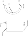
- the batteries may be formed as flat elements.
- a rectangular outline 310 of the battery element may be depicted with an anode connection 311 and a cathode connection 312.
- a circular outline 330 of a battery element may be depicted with an anode connection 331 and a cathode connection 332.
- the outlines of the battery form may be dimensionally and geometrically configured to fit in custom products.
- custom "free-form” or “free shape” outlines may be formed which may allow the battery configuration to be optimized to fit within a given product.
- a "free-form" example of a flat outline may be arcuate in form.
- the free form may be of such geometry that when formed to a three-dimensional shape, it may take the form of a conical, annular skirt that fits within the constraining confines of a contact lens. It may be clear that similar beneficial geometries may be formed where medical devices have restrictive 2D or 3D shape requirements.
- Another area for design considerations may relate to electrical requirements of the device, which may be provided by the battery.
- an appropriate battery may need to meet the full electrical requirements of the system when operating in a non-connected or non-externally powered mode.
- An emerging field of non-connected or non-externally powered biomedical devices may include, for example, vision-correcting contact lenses, health monitoring devices, pill cameras, and novelty devices.
- Recent developments in integrated circuit (IC) technology may permit meaningful electrical operation at very low current levels, for example, Pico amps of standby current and micro amps of operating current. IC's may also permit very small devices.
- Microbatteries for biomedical applications may be required to meet many simultaneous, challenging requirements.
- the microbattery may be required to have the capability to deliver a suitable operating voltage to an incorporated electrical circuit.
- This operating voltage may be influenced by several factors including the IC process "node,” the output voltage from the circuit to another device, and a particular current consumption target which may also relate to a desired device lifetime.
- nodes may typically be differentiated by the minimum feature size of a transistor, such as its "so-called" transistor channel.
- This physical feature along with other parameters of the IC fabrication, such as gate oxide thickness, may be associated with a resulting rating standard for "turn-on” or “threshold” voltages of field-effect transistors (FET's) fabricated in the given process node.
- FET's field-effect transistors
- it may be common to find FET's with turn-on voltages of 5.0V.
- the FET's may turn-on at 1.2, 1.8, and 2.5V.
- the IC foundry may supply standard cells of digital blocks, for example, inverters and flip-flops that have been characterized and are rated for use over certain voltage ranges.
- Designers chose an IC process node based on several factors including density of digital devices, analog/digital mixed signal devices, leakage current, wiring layers, and availability of specialty devices such as high-voltage FET's. Given these parametric aspects of the electrical components, which may draw power from a microbattery, it may be important for the microbattery power source to be matched to the requirements of the chosen process node and IC design, especially in terms of available voltage and current.
- an electrical circuit powered by a microbattery may connect to another device.
- the microbattery-powered electrical circuit may connect to an actuator or a transducer.
- these may include a light-emitting diode (LED), a sensor, a microelectromechanical system (MEMS) pump, or numerous other such devices.
- LED light-emitting diode
- MEMS microelectromechanical system
- such connected devices may require higher operating voltage conditions than common IC process nodes. For example, a variable-focus lens may require 35V to activate. The operating voltage provided by the battery may therefore be a critical consideration when designing such a system.
- the efficiency of a lens driver to produce 35V from a 1V battery may be significantly less than it might be when operating from a 2V battery. Further requirements, such as die size, may be dramatically different considering the operating parameters of the microbattery as well.
- the open-circuit voltage is the potential produced by the battery cell with infinite load resistance.
- the loaded voltage is the potential produced by the cell with an appropriate, and typically also specified, load impedance placed across the cell terminals.
- the cutoff voltage is typically a voltage at which most of the battery has been discharged.
- the cutoff voltage may represent a voltage, or degree of discharge, below which the battery should not be discharged to avoid deleterious effects such as excessive gassing.
- the cutoff voltage may typically be influenced by the circuit to which the battery is connected, not just the battery itself, for example, the minimum operating voltage of the electronic circuit.
- an alkaline cell may have an open-circuit voltage of 1.6V, a loaded voltage in the range 1.0 to 1.5V, and a cutoff voltage of 1.0V.
- the voltage of a given microbattery cell design may depend upon other factors of the cell chemistry employed. And, different cell chemistry may therefore have different cell voltages.
- Cells may be connected in series to increase voltage; however, this combination may come with tradeoffs to size, internal resistance, and battery complexity. Cells may also be combined in parallel configurations to decrease resistance and increase capacity; however, such a combination may tradeoff size and shelf life.
- Battery capacity may be the ability of a battery to deliver current, or do work, for a period of time. Battery capacity may typically be specified in units such as micro amp-hours. A battery that may deliver 1 micro amp of current for 1 hour has 1 micro amp-hour of capacity. Capacity may typically be increased by increasing the mass (and hence volume) of reactants within a battery device; however, it may be appreciated that biomedical devices may be significantly constrained on available volume. Battery capacity may also be influenced by electrode and electrolyte material.
- a battery may be required to source current over a range of values.
- a leakage current on the order of Pico amps to nano amps may flow through circuits, interconnects, and insulators.
- circuitry may consume quiescent current to sample sensors, run timers, and perform such low power consumption functions.
- Quiescent current consumption may be on the order of nano amps to milliamps.
- Circuitry may also have even higher peak current demands, for example, when writing flash memory or communicating over radio frequency (RF). This peak current may extend to tens of milliamps or more.
- RF radio frequency
- Shelf life typically refers to the period of time which a battery may survive in storage and still maintain useful operating parameters. Shelf life may be particularly important for biomedical devices for several reasons. Electronic devices may displace non-powered devices, as for example may be the case for the introduction of an electronic contact lens. Products in these existing market spaces may have established shelf life requirements, for example, three years, due to customer, supply chain, and other requirements. It may typically be desired that such specifications not be altered for new products. Shelf life requirements may also be set by the distribution, inventory, and use methods of a device including a microbattery. Accordingly, microbatteries for biomedical devices may have specific shelf life requirements, which may be, for example, measured in the number of years.
- three-dimensional biocompatible energization elements may be rechargeable.
- an inductive coil may also be fabricated on the three-dimensional surface. The inductive coil could then be energized with a radio-frequency ("RF") fob.
- the inductive coil may be connected to the three-dimensional biocompatible energization element to recharge the energization element when RF is applied to the inductive coil.
- photovoltaics may also be fabricated on the three-dimensional surface and connected to the three-dimensional biocompatible energization element. When exposed to light or photons, the photovoltaics will produce electrons to recharge the energization element.
- a battery may function to provide the electrical energy for an electrical system.
- the battery may be electrically connected to the circuit of the electrical system.
- the connections between a circuit and a battery may be classified as interconnects. These interconnects may become increasingly challenging for biomedical microbatteries due to several factors.
- powered biomedical devices may be very small thus allowing little area and volume for the interconnects. The restrictions of size and area may impact the electrical resistance and reliability of the interconnections.
- a battery may contain a liquid electrolyte which could boil at high temperature. This restriction may directly compete with the desire to use a solder interconnect which may, for example, require relatively high temperatures such as 250 degrees Celsius to melt.
- the battery chemistry, including the electrolyte, and the heat source used to form solder based interconnects may be isolated spatially from each other. In the cases of emerging biomedical devices, the small size may preclude the separation of electrolyte and solder joints by sufficient distance to reduce heat conduction.
- Interconnects may allow current to flow to and from the battery in connection with an external circuit. Such interconnects may interface with the environments inside and outside the battery, and may cross the boundary or seal between those environments. These interconnects may be considered as traces, making connections to an external circuit, passing through the battery seal, and then connecting to the current collectors inside the battery. As such, these interconnects may have several requirements. Outside the battery, the interconnects may resemble typical printed circuit traces. They may be soldered to, or otherwise connect to, other traces. In an example, where the battery is a separate physical element from a circuit board comprising an integrated circuit, the battery interconnect may allow for connection to the external circuit. This connection may be formed with solder, conductive tape, conductive ink or epoxy, or other means. The interconnect traces may need to survive in the environment outside the battery, for example, not corroding in the presence of oxygen.
- Adhesion may be required between the seal and interconnect in addition to the adhesion which may be required between the seal and battery package.
- Seal integrity may need to be maintained in the presence of electrolyte and other materials inside the battery.
- Interconnects which may typically be metallic, may be known as points of failure in battery packaging. The electrical potential and/or flow of current may increase the tendency for electrolyte to "creep" along the interconnect. Accordingly, an interconnect may need to be engineered to maintain seal integrity.
- the interconnects may interface with the current collectors or may actually form the current collectors.
- the interconnect may need to meet the requirements of the current collectors as described herein, or may need to form an electrical connection to such current collectors.
- metal foils are available in thickness of 25 microns or less, which make them suitable for very thin batteries. Such foil may also be sourced with low surface roughness and contamination, two factors which may be critical for battery performance.
- the foils may include zinc, nickel, brass, copper, titanium, other metals, and various alloys.
- a modular battery component may be formed according to some aspects and examples of the present invention.
- the modular battery assembly may be a separate component from other parts of the biomedical device.
- such a design may include a modular battery that is separate from the rest of a media insert.
- a modular battery component may be formed in a separate, non-integrated process which may alleviate the need to handle rigid, three-dimensionally formed optical plastic components.
- the sources of manufacturing may be more flexible and may operate in a more parallel mode to the manufacturing of the other components in the biomedical device.
- the fabrication of the modular battery components may be decoupled from the characteristics of three-dimensional (3D) shaped devices.
- 3D three-dimensional
- a modular battery system may be fabricated in a flat or roughly two-dimensional (2D) perspective and then shaped to the appropriate three-dimensional shape.
- a modular battery component may be tested independently of the rest of the biomedical device and yield loss due to battery components may be sorted before assembly.
- the resulting modular battery component may be utilized in various media insert constructs that do not have an appropriate rigid region upon which the battery components may be formed; and, in a still further example, the use of modular battery components may facilitate the use of different options for fabrication technologies than might otherwise be utilized, such as, web-based technology (roll to roll), sheet-based technology (sheet-to-sheet), printing, lithography, and "squeegee" processing.
- the discrete containment aspect of such a device may result in additional material being added to the overall biomedical device construct. Such effects may set a constraint for the use of modular battery solutions when the available space parameters require minimized thickness or volume of solutions.
- Battery shape requirements may be driven at least in part by the application for which the battery is to be used.
- Traditional battery form factors may be cylindrical forms or rectangular prisms, made of metal, and may be geared toward products which require large amounts of power for long durations. These applications may be large enough that they may comprise large form factor batteries.
- planar (2D) solid-state batteries are thin rectangular prisms, typically formed upon inflexible silicon or glass. These planar solid-state batteries may be formed in some examples using silicon wafer-processing technologies.
- low power, flexible batteries may be formed in a pouch construct, using thin foils or plastic to contain the battery chemistry. These batteries may be made flat (2D), and may be designed to function when bowed to a modest out-of-plane (3D) curvature.
- the form factor may require a three-dimensional curvature of the battery component where a radius of that curvature may be on the order of approximately 8.4 mm.
- the nature of such a curvature may be considered to be relatively steep and for reference may approximate the type of curvature found on a human fingertip.
- the nature of a relative steep curvature creates challenging aspects for manufacture.
- a modular battery component may be designed such that it may be fabricated in a flat, two-dimensional manner and then formed into a three-dimensional form of relative high curvature.
- the thickness of the battery component may be an important and limiting parameter.
- battery thickness may be determined by the combined thicknesses of top and bottom sheets, spacer sheets, and adhesive layer thicknesses. Practical manufacturing aspects may drive certain parameters of film thickness to standard values in available sheet stock.
- the films may have minimum thickness values to which they may be specified base upon technical considerations relating to chemical compatibility, moisture/gas impermeability, surface finish, and compatibility with coatings that may be deposited upon the film layers.
- a desired or goal thickness of a finished battery component may be a component thickness that is less than 220 ⁇ m.
- this desired thickness may be driven by the three-dimensional geometry of an exemplary ophthalmic lens device where the battery component may need to be fit inside the available volume defined by a hydrogel lens shape given end user comfort, biocompatibility, and acceptance constraints.
- This volume and its effect on the needs of battery component thickness may be a function of total device thickness specification as well as device specification relating to its width, cone angle, and inner diameter.
- Another important design consideration for the resulting battery component design may relate to the volume available for active battery chemicals and materials in a given battery component design with respect to the resulting chemical energy that may result from that design. This resulting chemical energy may then be balanced for the electrical requirements of a functional biomedical device for its targeted life and operating conditions
- a flexible battery module may facilitate the previously mentioned ability to fabricate the battery form in a two-dimensional (2D) flat form.
- the flexibility of the form may allow the two-dimensional battery to then be formed into an appropriate 3D shape to fit into a biomedical device such as a contact lens.
- a contact lens form of a biomedical device may have advantages for insertion/removal of the media insert based contact lens that may be closer to the insertion/removal of a standard, non-filled hydrogel contact lens.
- the number of flexures may be important to the engineering of the battery. For example, a battery which may only flex one time from a planar form into a shape suitable for a contact lens may have significantly different design from a battery capable of multiple flexures.
- the flexure of the battery may also extend beyond the ability to mechanically survive the flexure event.
- an electrode may be physically capable of flexing without breaking, but the mechanical and electrochemical properties of the electrode may be altered by flexure. Flex-induced changes may appear instantly, for example, as changes to impedance, or flexure may introduce changes which are only apparent in long-term shelf life testing.
- the battery width requirement may be largely a function of the application in which it is applied.
- a contact lens battery system may have constrained needs for the specification on the width of a modular battery component.
- the variable optic portion of the device may occupy a central spherical region of about 7.0 mm in diameter.
- the exemplary battery elements may be considered as a three-dimensional object, which fits as an annular, conical skirt around the central optic and formed into a truncated conical ring.
- the required maximum diameter of the rigid insert is a diameter of 8.50 mm, and tangency to a certain diameter sphere may be targeted (as for example in a roughly 8.40 mm diameter), then geometry may dictate what the allowable battery width may be.
- geometric models that may be useful for calculating desirable specifications for the resulting geometry which in some examples may be termed a conical frustum flattened into a sector of an annulus.
- Flattened battery width may be driven by two features of the battery element, the active battery components and seal width.
- a target thickness may be between 0.100 mm and 0.500 mm per side, and the active battery components may be targeted at approximately 0.800 mm wide.
- Other biomedical devices may have differing design constraints but the principles for flexible flat battery elements may apply in similar fashion.
- Moisture barriers may be designed to keep the internal moisture level at a designed level, within some tolerance.
- a moisture barrier may be divided into two sections or components; namely, the package and the seal.
- Polymer electrolytes may have an inherent advantage in that any leaking of moisture into the polymer electrolyte from external regions may have minimal impact, and may even improve battery performance in some examples. Thus, the importance of packaging requirements may be inherently reduced for polymer electrolyte batteries.
- the package may refer to the main material of the enclosure.
- the package may comprise a bulk material.
- the Water Vapor Transmission Rate (WVTR) may be an indicator of performance, with ISO, ASTM standards controlling the test procedure, including the environmental conditions operant during the testing.
- WVTR for a good battery package may be "zero."
- Exemplary materials with a near-zero WVTR may be glass and metal foils.
- Plastics, on the other hand may be inherently porous to moisture, and may vary significantly for different types of plastic. Engineered materials, laminates, or co-extrudes may usually be hybrids of the common package materials.
- the seal may be the interface between two of the package surfaces.
- the connecting of seal surfaces finishes the enclosure along with the package.
- the nature of seal designs may make them difficult to characterize for the seal's WVTR due to difficulty in performing measurements using an ISO or ASTM standard, as the sample size or surface area may not be compatible with those procedures.
- a practical manner to testing seal integrity may be a functional test of the actual seal design, for some defined conditions.
- Seal performance may be a function of the seal material, the seal thickness, the seal length, the seal width, and the seal adhesion or intimacy to package substrates.
- seals may be formed by a welding process that may involve thermal, laser, solvent, friction, ultrasonic, or arc processing.
- seals may be formed through the use of adhesive sealants such as glues, epoxies, acrylics, natural rubber, and synthetic rubber.
- adhesive sealants such as glues, epoxies, acrylics, natural rubber, and synthetic rubber.
- gasket type material may be formed from cork, natural and synthetic rubber, polytetrafluoroethylene (PTFE), polypropylene, and silicones to mention a few non-limiting examples.
- the batteries according to the present invention may be designed to have a specified operating life.
- the operating life may be estimated by determining a practical amount of moisture permeability that may be obtained using a particular battery system and then estimating when such a moisture leakage may result in an end of life condition for the battery.
- the packaging may desirably be predominantly foil and/or film based where these packaging layers may be as thin as possible, for example, 10 to 50 microns.
- the packaging may provide a sufficient diffusion barrier to moisture gain or loss during the shelf life.
- the packaging may provide a sufficient diffusion barrier to oxygen ingress to limit degradation of zinc anodes by direct oxidation.
- the packaging may provide a finite permeation pathway to hydrogen gas that may evolve due to direct reduction of water by zinc. And, the packaging may desirably sufficiently contain and may isolate the contents of the battery such that potential exposure to a user may be minimized.
- packaging constructs may include the following types of functional components: top and bottom packaging layers, pressure sensitive adhesive (PSA) layers, spacer layers, interconnect zones, filling ports, and secondary packaging.
- PSA pressure sensitive adhesive
- top and bottom packaging layers may comprise metallic foils or polymer films.
- Top and bottom packaging layers may comprise multi-layer film constructs containing a plurality of polymer and/or barrier layers. Such film constructs may be referred to as coextruded barrier laminate films.
- An example of a commercial coextruded barrier laminate film of particular utility in the present invention may be 3M ® Scotchpak 1109 backing which consists of a polyethylene terephthalate (PET) carrier web, a vapor-deposited aluminum barrier layer, and a polyethylene layer including a total average film thickness of 33 microns. Numerous other similar multilayer barrier films may be available and may be used in alternate examples of the present invention.
- packaging layer surface roughness may be of particular importance because the PSA may also need to seal opposing packaging layer faces.
- Surface roughness may result from manufacturing processes used in foil and film production, for example, processes employing rolling, extruding, embossing and/or calendaring, among others. If the surface is too rough, PSA may be not able to be applied in a uniform thickness when the desired PSA thickness may be on the order of the surface roughness Ra (the arithmetic average of the roughness profile). Furthermore, PSA's may not adequately seal against an opposing face if the opposing face has roughness that may be on the order of the PSA layer thickness.
- packaging materials having a surface roughness, Ra, less than 10 microns may be acceptable examples.
- surface roughness values may be 5 microns or less.
- the surface roughness may be 1 micron or less.
- Surface roughness values may be measured by a variety of methods including but not limited to measurement techniques such as white light interferometry, stylus profilometry, and the like. There may be many examples in the art of surface metrology that surface roughness may be described by a number of alternative parameters and that the average surface roughness, Ra, values discussed herein may be meant to be representative of the types of features inherent in the aforementioned manufacturing processes.
- the cathode current collector may be a sintered carbon rod.
- This type of material may face technical hurdles for thin electrochemical cells of the present invention.
- printed carbon inks may be used in thin electrochemical cells to replace a sintered carbon rod for the cathode current collector, and in these examples, the resulting device may be formed without significant impairment to the resulting electrochemical cell.
- said carbon inks may be applied directly to packaging materials which may comprise polymer films, or in some cases metal foils. In the examples where the packaging film may be a metal foil, the carbon ink may need to protect the underlying metal foil from chemical degradation and/or corrosion by the electrolyte.
- the carbon ink current collector may need to provide electrical conductivity from the inside of the electrochemical cell to the outside of the electrochemical cell, implying sealing around or through the carbon ink. Due to the porous nature of carbon inks, this may be not easily accomplished without significant challenges. Carbon inks also may be applied in layers that have finite and relatively small thickness, for example, 10 to 20 microns. In a thin electrochemical cell design in which the total internal package thickness may only be about 100 to 150 microns, the thickness of a carbon ink layer may take up a significant fraction of the total internal volume of the electrochemical cell, thereby negatively impacting electrical performance of the cell.
- the thin nature of the overall battery and the current collector in particular may imply a small cross-sectional area for the current collector.
- the bulk resistivity of carbon ink may be insufficient to meet the resistance requirement of thin batteries.
- Inks filled with silver or other conductive metals may also be considered to decrease resistance and/or thickness, but they may introduce new challenges such as incompatibility with novel electrolytes.
- Such metal foils may have significantly lower resistivity, thereby allowing them to meet electrical resistance requirements with much less thickness than printed carbon inks.
- one or more of the top and/or bottom packaging layers may serve as a substrate for a sputtered current collector metal or metal stack.
- 3M ® Scotchpak 1109 backing may be metallized using physical vapor deposition (PVD) of one or more metallic layers useful as a current collector for a cathode.
- PVD physical vapor deposition
- Exemplary metal stacks useful as cathode current collectors may be Ti-W (titanium-tungsten) adhesion layers and Ti (titanium) conductor layers.
- Exemplary metal stacks useful as anode current collectors may be Ti-W adhesion layers, Au (gold) conductor layers, and In (indium) deposition layers.
- the thickness of the PVD layers may be less than 500 nm in total.
- the electrochemical and barrier properties may need to be compatible with the battery.
- copper may be electroplated on top of a seed layer to grow a thick layer of conductor. Additional layers may be plated upon the copper.
- copper may be electrochemically incompatible with certain electrolytes especially in the presence of zinc. Accordingly, if copper is used as a layer in the battery, it may need to be sufficiently isolated from the battery electrolyte. Alternatively, copper may be excluded or another metal substituted.
- top and/or bottom packaging foils may also function as current collectors.
- a 25 micron brass foil may be useful as an anode current collector for a zinc anode.
- the brass foil may be optionally electroplated with indium prior to electroplating with zinc.
- cathode current collector packaging foils may comprise titanium foil, Hastelloy C-276 foil, chromium foil, and/or tantalum foil.
- one or more packaging foils may be fine blanked, embossed, etched, textured, laser machined, or otherwise processed to provide desirable form, surface roughness, and/or geometry to the final cell packaging.
- a cathode mixture which may be a term for a chemical formulation used to form a battery's cathode, may be applied as a paste, gel, suspension, or slurry, and may comprise a transition metal oxide such as manganese dioxide, some form of conductive additive which, for example, may be a form of conductive powder such as carbon black or graphite, and a water-soluble polymer such as polyvinylpyrrolidone (PVP) or some other binder additive.
- PVP polyvinylpyrrolidone
- the cathode mixture may have a desirable rheology that allows it to either be dispensed onto desired portions of the separator and/or cathode current collector, or squeegeed through a screen or stencil in a similar manner.
- the cathode mixture may be dried before being used in later cell assembly steps, while in other examples, the cathode may contain some or all of the electrolyte components, and may only be partially dried to a selected moisture content.
- the transition metal oxide may, for example, be manganese dioxide.
- the manganese dioxide which may be used in the cathode mixture may be, for example, electrolytic manganese dioxide (EMD) due to the beneficial additional specific energy that this type of manganese dioxide provides relative to other forms, such as natural manganese dioxide (NMD) or chemical manganese dioxide (CMD).
- EMD electrolytic manganese dioxide
- NMD natural manganese dioxide
- CMD chemical manganese dioxide
- the EMD useful in batteries of the present invention may need to have a particle size and particle size distribution that may be conducive to the formation of depositable or printable cathode mixture pastes/slurries.
- the EMD may be processed to remove significant large particulate components that may be considered large relative to other features such as battery internal dimensions, separator thicknesses, dispense tip diameters, stencil opening sizes, or screen mesh sizes. Particle size optimization may also be used to improve performance of the battery, for example, internal impedance and discharge capacity.
- Milling is the reduction of solid materials from one average particle size to a smaller average particle size, by crushing, grinding, cutting, vibrating, or other processes. Milling may also be used to free useful materials from matrix materials in which they may be embedded, and to concentrate minerals.
- a mill is a device that breaks solid materials into smaller pieces by grinding, crushing, or cutting. There may be several means for milling and many types of materials processed in them. Such means of milling may include: ball mill, bead mill, mortar and pestle, roller press, and jet mill among other milling alternatives. One example of milling may be jet milling. After the milling, the state of the solid is changed, for example, the particle size, the particle size disposition and the particle shape.
- Aggregate milling processes may also be used to remove or separate contamination or moisture from aggregate to produce "dry fills" prior to transport or structural filling.
- Some equipment may combine various techniques to sort a solid material into a mixture of particles whose size is bounded by both a minimum and maximum particle size. Such processing may be referred to as “classifiers” or “classification.”
- Milling may be one aspect of cathode mixture production for uniform particle size distribution of the cathode mixture ingredients. Uniform particle size in a cathode mixture may assist in viscosity, rheology, electroconductivity, and other properties of a cathode. Milling may assist these properties by controlling agglomeration, or a mass collection, of the cathode mixture ingredients. Agglomeration - the clustering of disparate elements, which in the case of the cathode mixture, may be carbon allotropes and transition metal oxides - may negatively affect the filling process by leaving voids.
- filtration may be another important step for the removal of agglomerated or unwanted particles.
- Unwanted particles may include over-sized particles, contaminates, or other particles not explicitly accounted for in the preparation process.
- Filtration may be accomplished by means such as filter-paper filtration, vacuum filtration, chromatography, microfiltration, and other means of filtration.
- EMD may have an average particle size of 7 microns with a large particle content that may contain particulates up to about 70 microns.
- the EMD may be sieved, further milled, or otherwise separated or processed to limit large particulate content to below a certain threshold, for example, 25 microns or smaller.
- the cathode may also comprise silver dioxide or nickel oxyhydroxide. Such materials may offer increased capacity and less decrease in loaded voltage during discharge relative to manganese dioxide, both desirable properties in a battery. Batteries based on these cathodes may have current examples present in industry and literature.
- a novel microbattery utilizing a silver dioxide cathode may include a biocompatible electrolyte, for example, one comprising zinc chloride and/or ammonium chloride instead of potassium hydroxide.
- the cathode mixture may include a polymeric binder.
- the binder may serve a number of functions in the cathode mixture.
- the primary function of the binder may be to create a sufficient inter-particle electrical network between EMD particles and carbon particles.
- a secondary function of the binder may be to facilitate mechanical adhesion and electrical contact to the cathode current collector.
- a third function of the binder may be to influence the rheological properties of the cathode mixture for advantageous dispensing and/or stenciling/screening.
- a fourth function of the binder may be to enhance the electrolyte uptake and distribution within the cathode.
- the choice of the binder polymer as well as the amount to be used may be beneficial to the function of the cathode in the electrochemical cell of the present invention. If the binder polymer is too soluble in the electrolyte to be used, then the primary function of the binder - electrical continuity - may be drastically impacted to the point of cell non-functionality. On the contrary, if the binder polymer is insoluble in the electrolyte to be used, portions of EMD may be ionically insulated from the electrolyte, resulting in diminished cell performance such as reduced capacity, lower open circuit voltage, and/or increased internal resistance.
- the binder may be hydrophobic; it may also be hydrophilic.
- binder polymers useful for the present invention comprise PVP, polyisobutylene (PIB), rubbery triblock copolymers comprising styrene end blocks such as those manufactured by Kraton Polymers, styrene-butadiene latex block copolymers, polyacrylic acid, hydroxyethylcellulose, carboxymethylcellulose, fluorocarbon solids such as polytetrafluoroethylene, among others.
- a solvent may be one component of the cathode mixture.
- a solvent may be useful in wetting the cathode mixture, which may assist in the particle distribution of the mixture.
- a solvent may be toluene.
- a surfactant may be useful in wetting, and thus distribution, of the cathode mixture.
- a surfactant may be a detergent, such as TritonTM QS-44. TritonTM QS-44 may assist in the dissociation of aggregated ingredients in the cathode mixture, allowing for a more uniform distribution of the cathode mixture ingredients.
- a conductive carbon may typically be used in the production of a cathode. Carbon is capable of forming many allotropes, or different structural modifications. Different carbon allotropes have different physical properties allowing for variation in electroconductivity. For example, the "springiness" of carbon black may help with adherence of a cathode mixture to a current collector. However, in energization elements requiring relatively low amounts of energy, these variations in electroconductivity may be less important than other favorable properties such as density, particle size, heat conductivity, and relative uniformity, among other properties.
- carbon allotropes examples include: diamond, graphite, graphene, amorphous carbon (informally called carbon black), buckminsterfullerenes, glassy carbon (also called vitreous carbon), carbon aerogels, and other possible forms of carbon capable of conducting electricity.
- a carbon allotrope may be graphite.
- the mixture may be dispensed, applied, and/or stored onto a surface such as the hydrogel separator, or the cathode current collector, or into a volume such as the cavity in the laminar structure. Filing onto a surface may result in a volume being filled over time.
- a certain rheology may be desired to optimize the dispensing, applying, and/or storing process. For example, a less viscous rheology may allow for better filling of the cavity while at the same time possibly sacrificing particle distribution. A more viscous rheology may allow for optimized particle distribution, while possibly decreasing the ability to fill the cavity and possibly losing electroconductivity.
- the anode for the laminar battery of the present invention may, for example, comprise zinc.
- a zinc anode may take the physical form of a can in which the contents of the electrochemical cell may be contained.
- a zinc can may be an example but there may be other physical forms of zinc that may prove desirable to realize ultra-small battery designs.
- Electroplating of zinc is a process type in numerous industrial uses, for example, for the protective or aesthetic coating of metal parts.
- electroplated zinc may be used to form thin and conformal anodes useful for batteries of the present invention.
- the electroplated zinc may be patterned in many different configurations, depending on the design intent.
- a facile means for patterning electroplated zinc may be processing with the use of a photomask or a physical mask.
- a photoresist may be applied to a conductive substrate, the substrate on which zinc may subsequently be plated.
- the desired plating pattern may be then projected to the photoresist by means of a photomask, thereby causing curing of selected areas of photoresist.
- the uncured photoresist may then be removed with appropriate solvent and cleaning techniques.
- the result may be a patterned area of conductive material that may receive an electroplated zinc treatment. While this method may provide benefit to the shape or design of the zinc to be plated, the approach may require use of available photopatternable materials, which may have constrained properties to the overall cell package construction. Consequently, new and novel methods for patterning zinc may be required to realize some designs of thin microbatteries of the present invention.
- An alternative means of patterning zinc anodes may be by means of a physical mask application.
- a physical mask may be made by cutting desirable apertures in a film having desirable barrier and/or packaging properties.
- the film may have pressure-sensitive adhesive applied to one or both sides.
- the film may have protective release liners applied to one or both adhesives. The release liner may serve the dual purpose of protecting the adhesive during aperture cutting and protecting the adhesive during specific processing steps of assembling the electrochemical cell, specifically the cathode filling step.
- a zinc mask may comprise a PET film of approximately 100 microns thickness to which a pressure-sensitive adhesive may be applied to both sides in a layer thickness of approximately 10-20 microns.
- Both PSA layers may be covered by a PET release film which may have a low surface energy surface treatment, and may have an approximate thickness of 50 microns.
- the multi-layer zinc mask may comprise PSA and PET film.
- PET films and PET/PSA zinc mask constructs as described herein may be desirably processed with precision nanosecond laser micromachining equipment, such as, Oxford Lasers E-Series laser micromachining workstation, to create ultra-precise apertures in the mask to facilitate later plating.
- nanosecond laser micromachining equipment such as, Oxford Lasers E-Series laser micromachining workstation
- the zinc mask may be placed and then electroplating of one or more metallic materials may be performed.
- zinc may be electroplated directly onto an electrochemically compatible anode current collector foil such as brass.
- anode side packaging comprises a polymer film or multi-layer polymer film upon which seed metallization has been applied
- zinc, and/or the plating solutions used for depositing zinc may not be chemically compatible with the underlying seed metallization. Manifestations of lack of compatibility may include film cracking, corrosion, and/or exacerbated H 2 evolution upon contact with cell electrolyte. In such a case, additional metals may be applied to the seed metal to affect better overall chemical compatibility in the system.
- One metal that may find particular utility in electrochemical cell constructions may be indium.
- Indium may be widely used as an alloying agent in battery grade zinc with its primary function being to provide an anti-corrosion property to the zinc in the presence of electrolyte.
- indium may be successfully deposited on various seed metallizations such as Ti-W and Au. Resulting films of 1-3 microns of indium on said seed metallization layers may be low-stress and adherent. In this manner, the anode-side packaging film and attached current collector having an indium top layer may be conformable and durable.
- nodules of zinc may be observed to form on the underlying smooth indium deposit.
- the vertical space allowance for the zinc anode layer may be up to about 5-10 microns thick, but in some examples, lower current densities may be used for zinc plating, and the resulting nodular growths may grow taller than the desired maximum anode vertical thickness. It may be that the nodular zinc growth stems from a combination of the high overpotential of indium and the presence of an oxide layer of indium.
- higher current density DC plating may overcome the relatively large nodular growth patterns of zinc on indium surfaces.
- 100 ASF plating conditions may result in nodular zinc, but the size of the zinc nodules may be drastically reduced compared to 20 ASF plating conditions.
- the number of nodules may be vastly greater under 100 ASF plating conditions.
- the resulting zinc film may ultimately coalesce to a more or less uniform layer with only some residual feature of nodular growth while meeting the vertical space allowance of about 5-10 microns.
- An added benefit of indium in the electrochemical cell may be reduction of H 2 formation, which may be a slow process that occurs in aqueous electrochemical cells containing zinc.
- the indium may be beneficially applied to one or more of the anode current collector, the anode itself as a co-plated alloying component, or as a surface coating on the electroplated zinc.
- indium surface coatings may be desirably applied in-situ by way of an electrolyte additive such as indium trichloride or indium acetate. When such additives may be added to the electrolyte in small concentrations, indium may spontaneously plate on exposed zinc surfaces as well as portions of exposed anode current collector.
- Zinc and similar anodes commonly used in commercial primary batteries may typically be found in sheet, rod, and paste forms.
- the anode of a miniature, biocompatible battery may be of similar form, e.g. thin foil, or may be plated as previously mentioned.
- the properties of this anode may differ significantly from those in existing batteries, for example, because of differences in contaminants or surface finish attributed to machining and plating processes. Accordingly, the electrodes and electrolyte may require special engineering to meet capacity, impedance, and shelf life requirements. For example, special plating process parameters, plating bath composition, surface treatment, and electrolyte composition may be needed to optimize electrode performance.
- the electrolyte may be called a polymer electrolyte.
- the polymer electrolyte systems the polymer backbone has regions that become involved in the conduction mechanisms of the ions. As well, these regions of the polymer backbone also facilitate the dissolution of the salt ions into the electrolyte bulk. In general, higher levels of dissolved ions in an electrolyte bulk may result in better battery performance characteristics.
- polyethylene oxide (PEO) may be a common polymer constituent.
- the ionic conductivity of the system may improve at higher operating temperature conditions, but may be relatively poor at room temperature operating conditions.
- a sheet form of a polymer electrolyte may be formed including the presence of ionic species.
- the sheet form may be applied to an electrode with high temperature lamination processing.
- the electrolyte formulation may be coated upon an electrode surface.
- plasticized polymer electrolytes may be utilized in polymer electrolyte battery systems.
- polymer systems that may be useful to form plasticized polymer electrolytes including as non-limiting examples PEO, poly(methyl methacrylate) (PMMA) and poly(vinyl chloride) amongst other polymer systems.
- PEO poly(methyl methacrylate)
- PMMA poly(methyl methacrylate)
- PMMA poly(methyl methacrylate)
- VVC poly(vinyl chloride) amongst other polymer systems.
- the selected polymer backbone creates a two-dimensional or three-dimensional matrix into which a solvent and ionic solute system may be incorporated.
- the incorporation of the solvent system with dissolved ionic species "plasticizes" the polymer electrolyte.
- the backbone of a plasticized polymer electrolyte system may not participate in the ionic transport across the electrolyte.
- the presence of the solvent is another difference from the first class of polymer electrolyte systems and does act to facilitate ionic transfer.
- the ionic transport and related ionic conductivities of the battery structure may be higher in a plasticized polymer electrolyte system for these reasons.
- the matrix of the plasticized polymer electrolyte system may improve characteristics related to the interfaces that are formed between the electrolyte and its neighboring layers.
- the plasticized polymer electrolyte system may be laminated under high temperature conditions to improve adherence to the electrodes.
- a plasticizer for use with poly (vinylidenefluoride) (PVDF) polymer or poly(vinylidene fluoride-hexafluoropropylene) (PVDF-HFP) copolymer electrode member compositions is propylene carbonate (PC).
- the effective proportion of this plasticizer may depend not only on characteristics of a desired matrix polymer itself. The effective proportion may also be heavily influenced by the amounts and properties of other components of the composition, such as the volume and particle size of the active electrode material.
- an effective amount of PC in a positive electrode formulation with PVDF-HFP may vary from about 60 percent to 300 percent by weight of the electrode matrix polymer component.
- the amount of plasticizer in any formulation may be determined empirically in the rather broad range of effective amounts and may depend upon use conditions or on tested electrical results.
- gel electrolyte systems may be another type of electrolyte system used in polymer electrolyte batteries.
- a gel is a type of polymerization product that has different properties than a solidified polymer network. Gels consist of a solid three-dimensional network. The network typically may be formed by a copolymerization of branched monomers. The three dimensional network spans a volume of a liquid and binds it in place through surface tension effects.
- There may be numerous polymer systems that may form a gel electrolyte system such as PMMA, polyacrylonitrile (PAN), poly (vinylidene fluoride-hexafluoropropylene) (PVDF-HFP) and numerous other examples.
- the gel electrolytes may typically exhibit high ionic conductivity.
- High temperature lamination may be used to affix the gel polymer electrolyte to electrode surfaces with good adhesion characteristics.
- an electrolyte composition may be added to the attached gel polymer background much as a sponge absorbs a liquid composition.
- the various classes of polymer electrolyte layers may be used in examples of polymer electrolyte batteries.
- ions consistent with transport of the anode material away from the anode may be included in the electrolyte as it is formed or in some examples, such as with the gel polymer electrolyte system, added later.
- the polymer network of each of the classes creates a layer that may act as a separator for the batteries as well.
- a polymer electrolyte/separator film may be prepared by casting a portion of a coating composition onto a polished silicon wafer using a common spin-coating apparatus operated at a desired speed, such as 600 rpm, for a desired time, such as for 2 sec, to obtain a film of a desired thickness and uniformity.
- the film may be dried at room temperature for an appropriate time, such as for about 10 minutes within the confines of the coating apparatus.
- the coating composition may be prepared by suspending about 1.5 g of an 88:12 VDF:HFP copolymer of about 380x103 MW Kynar FLEX 2801 in about 9 g of anhydrous tetrohydrofuran (THF) and adding to this mixture about 1.5 g of a 1M solution of zinc acetate, or other appropriate electrolyte salts, in a 1:1 mixture by weight of ethylene carbonate (EC):propylene carbonate (PC).
- THF anhydrous tetrohydrofuran
- EC ethylene carbonate
- PC propylene carbonate
- the completed mixture may be warmed to an elevated temperature, such as about 60 degrees C for a period of time, such as 30 minutes, to facilitate dissolution. Occasional agitation of the solution may help to maintain the solution's fluidity.
- the resulting film may be used as a polymer electrolyte film according to the various examples to form battery cells presented in this discussion.
- a casting solution may be formed by mixing a roughly two-to-one ratio of poly(vinylidene fluoride) (PVDF) and poly(dimethylsiloxane) (PDMS) into a solvent mixture comprising N-N Dimethyl Acetamide (DMAc) and glycerol.
- PVDF poly(vinylidene fluoride)
- PDMS poly(dimethylsiloxane)
- the ratio of the DMAc to glycerol may be varied and may affect characteristics such as the porosity of the resulting separator layer.
- An excess of the solvent mixture may be used to allow for the shrinkage of the resulting layer in the cavity to form a thin separator layer.
- the resulting solution may be cast upon an electrolyte, rolled into a sheet, or extruded into a shape in some examples. Other manners of dispensing the casting solution may be consistent with the processes described herein.
- the structure may be immersed into a room temperature water bath for 20-40 hours to allow for the glycerol to dissolve out of the separator layer and result in a layer with a desired porosity.
- the polymer electrolyte layer may then be impregnated with a solution containing an appropriate solvent such as water and an electrolyte such as a zinc based salt.
- Electrodes may be laminated to the polymer electrolyte with a heated double-roll laminator device at about 110 degrees C and about 10 kg/cm roll pressure. After cooling, the laminate cell structure may be immersed in an appropriate solvent to extract electrode related plasticizer.
- the solvent may include acetone, diethyl ether or NMP.
- the resulting structure may then be air dried until the surface solvent evaporates and thereafter may be placed in a circulating air oven at elevated temperature such as about 70 degrees C for an hour or so to continue the removal of solvent, moisture and residual plasticizer.
- the processing may result in a well bonded work piece which may then be packaged in an hermetically sealed multilayer foil/polymer envelope in a helium atmosphere along with a measure of electrolyte such as a zinc salt dissolved in an appropriate solvent.
- the solvent and electrolyte may diffuse into the microporous membrane and impregnate it with electrically conductive electrolyte.
- a laminated electrochemical battery cell may be prepared by assembling the electrodes including the cathode and the anode respectively along with a Celgard 2300 microporous separator which may contain the electrolyte.
- the electrodes may be laminated to the separator with a heated double-roll laminator device at about 110 degrees C and about 10 kg/cm roll pressure.
- a demonstration of processing of a polymer electrolyte battery comprising a type of polymer electrolyte may be found.
- the various layers to be formed may be processed in various fashions and orders, but as an example, a process may start at Fig. 4A with obtaining a cathode collector 410.
- a thin foil or film of zinc metal may be used for the cathode collector.
- a surface treatment may be made to add a coating 415 to a surface of the titanium foil.
- the treatment may be a carbon coating such as offered by Lamart Corporation, Clifton, NJ, USA.
- a region of the titanium foil may be left untreated to form a cathode contact 416.
- the entire foil may be treated to add a coating, and the coating may be removed in a later step to expose the cathode contact 416.
- a cathode mixture may be added upon the coating to form a cathode 420.
- There may be numerous means to add the coating including spraying, printing, and depositing with a squeegee or knife edge type layering process.
- an amount of the cathode mixture may be deposited behind a knife edge while the knife edge is drawn along the cathode layer to result in a controlled layer with uniform thickness.
- a cathode may be formed by electrodepositing the cathode material upon a current conductor.
- a cathode powder blend composed of 88 percent Erachem MnO 2 powder, jet-milled by Hosikowa, may be combined with Super P Li carbon black, to a 5 percent composition and with Kynar 2801 PVDF to a 7 percent composition.
- An amount of zinc acetate may be dissolved in NMP such that when mixed with the cathode powder blend, the amount of zinc acetate is in a ratio of 1:10 for the zinc acetate mass to PVDF mass.
- the resulting slurry may be suspended in the NMP and this amount of NMP creates a formulation with 27 percent solids.
- the resulting slurry may be mixed with a magnetic stir bar for 10 to 20 hours at a rate such as at roughly 400 rpm.
- the mixed slurry may be degassed. Degassing may be processed with a Thinky ARE-250 planetary centrifugal mixer at 2000 rpm for about 2 minutes.
- the slurry may next be applied with a doctor blade to a thickness of about 30-80 microns.
- the slurry deposit may be made upon a sheet of 12.5 micron thick grade I titanium foil such as that available from Arnold Magnetics, which may be coated with a 1-3 micron thick layer of carbon.
- the cathode coating on the titanium foil may be dried in a heated laboratory oven for numerous hours, such as for a period of 18-24 hours where the temperature may In an example, be 50 degrees C.
- the polymer electrolyte 430 may be added to the growing structure.
- the gel polymer may be composed of Kynar 2801 with 30 weight percent zinc acetate. This mixture may be carried in a solvent blend including 36 percent DMSO and 64 percent NMP. This solution may then be applied to the cathode using a doctor blade.
- the resulting coating may be dried in a high temperature environment. In an example, the drying may be performed at around 50 degrees C in laboratory oven for a number of hours, such as 3-6 hours. In some examples, a further drying step at an even higher temperature such as 100 degrees C may be performed for some time, such as for 1 hour. This coating process may be repeated multiple times to achieve a targeted thickness.
- the polymer electrolyte layer may be applied in numerous manners such as by spray coating, printing, or squeegee or knife edge layering
- the deposited layer may be dried to remove an amount of the solvent.
- a zinc anode 440 may be applied to the polymer electrolyte layer. Further enablement for the formulations and processing of anodes in biomedical devices may be found as set forth in United States Patent Application No. 14/819,634 filed August 6, 2015 , which is incorporated herein by reference.
- the surface layer of the polymer electrolyte may have an additional amount of solvent or polymer electrolyte reapplied to aid in bonding between the polymer electrolyte and the anode layer.
- the bonding process may proceed with no solvent or polymer electrolyte reapplication.
- the lamination process will apply heat and pressure while evacuating the gas phase around the region being applied. Lamination of electrodes with coated polymer electrolytes may be carried out between heated pressure rollers at a temperature and pressure level which does not significantly affect the polymer structure.
- lamination may be carried out between 70 degrees C and 130 degrees C, preferably between 100 degrees C and 125 degrees C, and more preferably at about 110 degrees C.
- the pressure in some examples, may be a linear pressure load between about 20 and 180 kilograms per centimeter (kg/cm), preferably between about 55 and 125 kg/cm. It may be apparent that the optimum temperature and pressure conditions will depend on the particular laminator construction and mode of its use.
- rolls of material may be processed in the manners described in Figs. 4A - 4C and then come together in the hot vacuum lamination process related to Fig. 4D .
- This processing may be referred to as a roll to roll manufacturing process.
- the resulting polymer electrolyte battery device may be annealed in a thermal treatment 450 that will dry the structure.
- the thermal treatment may also improve characteristics at the newly formed interfaces between the collectors, cathode, electrolyte and anode.
- the function of the formed battery as well as its biocompatibility may depend strongly on encapsulating the polymer electrolyte battery structure in manners that isolate the battery structure from its environment while allowing battery contacts to be made to devices outside the encapsulation.
- the various means of encapsulation as have been discussed in sections on sealing and packaging heretofore may be used to perform the encapsulating step 460 illustrated in Fig. 4F .
- a pair of encapsulating films may be used to surround the battery element.
- the films may be precut in various locations to expose the regions where collector contacts are located. Thereafter, the two films may be brought around the battery element and joined together is a seal.
- the seal may be formed by thermally treating the sealing layers to flow into each other and form a seal.
- a laser may be used to form a seal.
- a subsequent process may singulate or cut out the battery elements from the resulting sheet that is formed.
- a laser may be used to cut out the batteries.
- a die may be used to punch out the battery elements with a specifically shaped cutting surface.
- some singulated battery designs may be rectilinear whereas other designs may be curvilinear, matching a curve of a contact lens insert piece for example.
- Exemplary samples of polymer electrolyte batteries have been formed utilizing the processing example referred to in relation to Figs. 4A- 4F .
- FIG 5A-D characterization results from the exemplary samples are found. Samples were formed with an overall form factor of 5 mm by 1 mm and a thickness of approximately 135 microns. For characterization data, the effective anode area for the battery samples was roughly 3x10 -3 cm 2 .
- the discharge characteristics of an exemplary battery cell may be found. A steady performance with a cell voltage of approximately 1.3V may be observed indicating good energy capacity and cell life performance.
- Fig. 5A the discharge characteristics of an exemplary battery cell may be found. A steady performance with a cell voltage of approximately 1.3V may be observed indicating good energy capacity and cell life performance.
- a cavity based laminate approach may provide means to manufacture polymer batteries of the type presented herein, an approach which may be particularly useful for batteries of curvilinear shape.
- the cavity may allow for features that provide registration marks for the alignment of the various processing steps. Additionally, for processing involving knife edge layer deposition, the presence of an aligned cavity may facilitate efficient utilization of chemicals and foils.
- the laminate structure may also support the contact films regardless of the thickness of such films for a particular battery design.
- the laminate layers used to form a cavity may also be subjected to punch type singulation in multiple steps.
- the desired boundary region around a battery element may be cut out with a punch where the collector and anode contacts are not singulated.
- the batteries may be encapsulated in sheet form. This may be of particular value for curvilinear shaped battery elements.
- FIGs. 6A-6C an example of a modified cavity based battery cell is depicted with exemplary sealing / diffusion aspects. Note that the battery shape depicted is rectilinear; however, it may be understood that curvilinear shapes follow much the same processing. Exemplary details for the processing steps, such as formulations of the cathode slurry and the electrolyte casting mixture may be similar or identical to the examples described earlier in this description; thus, summary description is provided for those steps in the following example.
- FIG. 6A a top-down view of an exemplary biocompatible energization element with polymer electrolytes and without encapsulation is illustrated.
- the peripheral region 601 may be isolated to allow for films from the top and bottom to encapsulate the energization element.
- the battery device may contain at least an anode current collector 602 with anode, and internal adhesives/sealants to connect the current collector to the laminate piece .
- the envelope capable of sealing the peripheral region 601 may comprise polymer film laminate pieces 609 capable of sealing, such as polypropylene as described in greater detail below.
- the internal adhesives/sealants may comprise pressure sensitive adhesives (PSA) such as polyisobutylene.
- PSA pressure sensitive adhesives
- Polyisobutylene may be a commercially-available material that may be formulated into PSA compositions meeting many if not all requirements. Furthermore, PIB may be an excellent barrier sealant with very low water absorbance and low oxygen permeability. An example of PIB useful in the examples of the present invention may be Oppanol® B15 by BASF Corporation.
- Fig. 6B illustrates an exemplary bottom-up view of the battery element without encapsulation.
- the periphery 601 of the device may be cut out from its surrounding layers and allow for encapsulation of the device in subsequent steps.
- seals may be formed by a welding process that may involve thermal, laser, solvent, friction, ultrasonic, or arc processing.
- seals may be formed through the use of adhesive sealants such as glues, epoxies, acrylics, natural rubber, and synthetic rubber.
- Other examples may derive from the utilization of gasket type material that may be formed from cork, natural and synthetic rubber, polytetrafluoroethylene (PTFE), polypropylene, and silicones to mention a few non-limiting examples.
- PTFE polytetrafluoroethylene
- Fig. 6C illustrates an exemplary long-edge cross sectional view of a polymer battery without encapsulation containing an anode current collector 602 where the anode current collector is the anode as well, a cathode current collector 604 with cathode 612, and a polymer electrolyte 610 which also functions as a separator, and adhesive/sealant 608 to seal the laminate pieces 609 to the associated collector layers and to each other.
- the periphery 601 of the device may be enveloped with sealing layers.
- the layers may enclose the components of the biocompatible energization element from the top and the bottom; the anode and cathode collector contacts are not sealed at the ends so that external contact may be made.
- FIG. 7A shows a cathode contact 710 with a carbon coating 715.
- the carbon coating may coat both sides of the cathode contact, a portion may be shielded or removed to expose a contact connection.
- the processing may continue to Fig. 7B , a laminate layer 720 with a release layer 721 may have a preformed cavity 722.
- the laminate layer 720 may be adhered to the cathode contact 710 upon the carbon coating 715.
- Fig. 7C a cathode slurry, as discussed in reference to Fig.
- the release layer may be removed, and the cathode layer may be dried by the various means as have been previously discussed. This forms the cathode pieces that may be joined to anode and electrolyte pieces. Exemplary processing steps to form the anode and electrolyte pieces follow in the next steps.
- an anode contact 750 which may be a zinc film as discussed in previous sections, or may be an anode film of various types may have a second laminate film 751 with a second cavity 753 placed thereon.
- the second cavity 753 may align with the first cavity 722 when the two pieces are ultimately brought together.
- the laminate piece may have a release layer 752.
- the second cavity may be filled with a polymer electrolyte formulation as described previously in this description to form the polymer electrolyte 760.
- the release layer 752 may be removed and the polymer electrolyte may be dried by various means.
- the two pieces, the laminate filled cathode and the laminate filed polymer electrolyte may be brought together as depicted in Fig. 7H .
- a vacuum laminator 770 may heat the two pieces and press them together to form the laminated piece as depicted at Fig. 7I .
- the laminate structure may have numerous alignment marks printed into the laminate body that may be used for alignment of the various processing and may align target regions around the battery body to be cut out by punching or laser cutting or by other means. The cutting may be used to cut out material around the battery.
- a top down view is shown with a battery body 780 that has had material from the laminate structure cut or punched out to form the gap 781.
- a subsequent sealing process with a foil above and below the battery layer may now create a seal fully around the battery body.
- the sealing foils above and below the battery body may have holes in them that align to desired contact points on the current collectors.
- tabs 782 to hold the battery bodies may be left connected to the battery.
- the sealant layers may not cover an end region of the batteries when these tabs 782 are subsequently cut to singulate the battery elements.
- the singulation means including laser cutting or heated die punching may create a seal in these layers as it cuts.
- a linear battery body is depicted, but curvilinear shapes may be processed in a similar manner using the steps as have been depicted.
- Well-designed sealing structures and the associated sealing materials may improve biocompatibility of the energization device as materials may be maintained in zones that have no interaction with biologically contacting surfaces.
- well-formed seals may improve the ability of the battery to receive forces of various kinds and not rupture exposing the contents of the cavity or cavities of a battery.
- the polymer electrolyte composition inherently improves biocompatibility of the energization element as well as its resiliency to effect from external diffusion into the battery.
- polymer electrolyte primary battery devices which have been formed according to the various manners described in the present invention.
- these battery devices may be incorporated into biomedical devices such as ophthalmic lenses as discussed in reference to Fig 1B .
- the battery device may be connected to an electroactive element where the battery resides within an insert with the electroactive element or outside the insert.
- the insert, the electroactive element and the battery as a whole may be encapsulated with appropriate hydrogel formulations to afford biocompatibility of the biomedical device.
- the hydrogel may contain formulations that retain the wetting aspects of the encapsulating hydrogel.
- the battery and the insert may interact with wet environments, and therefore the strategies for biocompatibility of the battery alone are very relevant to the overall biomedical device.
- seals prevent ingress and egress of materials into the insert and into the battery device.
- the design of the hydrogel encapsulating layer may be altered to allow wettability and permeability around the insert and the battery device, for example.
- gas evolution may allow some gas species to pass through battery devices, through hydrogel encapsulation and into the biomedical device environment.
- the portions of a biomedical device whether for an ophthalmic device or for other devices, that contact fluids and cell layers of a user may be designed for matching of the interface layers of the biomedical device to the biologic environment that the biomedical device will reside in or on.
- a preferred encapsulating material that may form an encapsulating layer in a biomedical device may include a silicone containing component.
- this encapsulating layer may form a lens skirt of a contact lens.
- a "silicone-containing component" is one that contains at least one [-Si-O-] unit in a monomer, macromer or prepolymer.
- the total Si and attached O are present in the silicone-containing component in an amount greater than about 20 weight percent, and more preferably greater than 30 weight percent of the total molecular weight of the silicone-containing component.
- Useful silicone-containing components preferably comprise polymerizable functional groups such as acrylate, methacrylate, acrylamide, methacrylamide, vinyl, N-vinyl lactam, N-vinylamide, and styryl functional groups.
- the ophthalmic lens skirt also called an insert-encapsulating layer, that surrounds the insert may be comprised of standard hydrogel ophthalmic lens formulations.
- Exemplary materials with characteristics that may provide an acceptable match to numerous insert materials may include, the Narafilcon family (including Narafilcon A and Narafilcon B), and the Etafilcon family (including Etafilcon A).
- Narafilcon family including Narafilcon A and Narafilcon B
- Etafilcon family including Etafilcon A
- Suitable silicone containing components include compounds of Formula I where
- “monovalent reactive groups” are groups that may undergo free radical and/or cationic polymerization.
- free radical reactive groups include (meth)acrylates, styryls, vinyls, vinyl ethers, C1-6alkyl(meth)acrylates, (meth)acrylamides, C1-6alkyl(meth)acrylamides, N-vinyllactams, N-vinylamides, C2-5alkenyls, C2-5alkenylphenyls, C2-5alkenylnaphthyls, C2-6alkenylphenylC1-6alkyls, O-vinylcarbamates and O-vinylcarbonates.
- Non-limiting examples of cationic reactive groups include vinyl ethers or epoxide groups and mixtures thereof.
- the free radical reactive groups comprises (meth)acrylate, acryloxy, (meth)acrylamide, and mixtures thereof.
- Suitable monovalent alkyl and aryl groups include unsubstituted monovalent C1 to C16alkyl groups, C6-C14 aryl groups, such as substituted and unsubstituted methyl, ethyl, propyl, butyl, 2-hydroxypropyl, propoxypropyl, polyethyleneoxypropyl, combinations thereof and the like.
- b is zero, one R1 is a monovalent reactive group, and at least 3 R1 are selected from monovalent alkyl groups having one to 16 carbon atoms, and in another example from monovalent alkyl groups having one to 6 carbon atoms.
- Non-limiting examples of silicone components of this embodiment include 2-methyl-,2-hydroxy-3-[3-[1,3,3,3-tetramethyl-1-[(trimethylsilyl)oxy]disiloxanyl]propoxy]propyl ester ("SiGMA”), 2-hydroxy-3-methacryloxypropyloxypropyl-tris (trimethylsiloxy)silane, 3-methacryloxypropyltris(trimethylsiloxy)silane (“TRIS”), 3-methacryloxypropylbis(trimethylsiloxy)methylsilane and 3-methacryloxypropylpentamethyl disiloxane.
- SiGMA 2-methyl-,2-hydroxy-3-[3-[1,3,3,3-tetramethyl-1-[(trimethylsilyl)oxy]disiloxanyl]propoxy]propyl ester
- TMS 3-methacryloxypropyltris(trimethylsiloxy)silane
- TMS 3-methacryloxypropylbis(trimethylsil
- b is 2 to 20, 3 to 15 or in some examples 3 to 10; at least one terminal R1 comprises a monovalent reactive group and the remaining R1 are selected from monovalent alkyl groups having 1 to 16 carbon atoms, and in another embodiment from monovalent alkyl groups having 1 to 6 carbon atoms.
- b is 3 to 15, one terminal R1 comprises a monovalent reactive group, the other terminal R1 comprises a monovalent alkyl group having 1 to 6 carbon atoms and the remaining R1 comprise monovalent alkyl group having 1 to 3 carbon atoms.
- Non-limiting examples of silicone components of this embodiment include (mono-(2-hydroxy-3-methacryloxypropyl)-propyl ether terminated polydimethylsiloxane (400-1000 MW)) (“OH-mPDMS”), monomethacryloxypropyl terminated mono-n-butyl terminated polydimethylsiloxanes (800-1000 MW), (“mPDMS”).
- both terminal R1 comprise monovalent reactive groups and the remaining R1 are independently selected from monovalent alkyl groups having 1 to 18 carbon atoms, which may have ether linkages between carbon atoms and may further comprise halogen.
- the lens of the present invention will be made from a reactive mixture comprising at least about 20 and preferably between about 20 and 70%wt silicone containing components based on total weight of reactive monomer components from which the polymer is made.
- one to four R1 comprises a vinyl carbonate or carbamate of the formula: wherein: Y denotes O-, S- or NH-; R denotes, hydrogen or methyl; d is 1, 2, 3 3 or 4; and q is 0 or 1.
- the silicone-containing vinyl carbonate or vinyl carbamate monomers specifically include: 1,3-bis[4-(vinyloxycarbonyloxy)but-1-yl]tetramethyl-disiloxane; 3-(vinyloxycarbonylthio) propyl-[tris (trimethylsiloxy)silane]; 3-[tris(trimethylsiloxy)silyl] propyl allyl carbamate; 3-[tris(trimethylsiloxy)silyl] propyl vinyl carbamate; trimethylsilylethyl vinyl carbonate; trimethylsilylmethyl vinyl carbonate, and
- R1 shall comprise a monovalent reactive group and no more than two of the remaining R1 groups will comprise monovalent siloxane groups.
- silicone-containing components includes polyurethane macromers of the following formulae:
- A denotes a divalent polymeric radical of formula:
- R11 independently denotes an alkyl or fluoro-substituted alkyl group having 1 to10 carbon atoms, which may contain ether linkages between carbon atoms; y is at least 1; and p provides a moiety weight of 400 to 10,000; each of E and E1 independently denotes a polymerizable unsaturated organic radical represented by formula: wherein: R5 is hydrogen or methyl; R13 is hydrogen, an alkyl radical having 1 to 6 carbon atoms, or a -CO-Y-R15 radical wherein Y is -O-,Y-S- or -NH-; R14 is a divalent radical having 1 to 5 carbon atoms; X denotes -CO- or -OCO-; Z denotes -O-or -NH-; Ar denotes an aromatic radical having 6 to 30 carbon atoms; w is 0 to 6; x is 0 or 1; y is 0 or 1; and z is 0 or 1.
- a preferred silicone-containing component is a polyurethane macromer represented by the following formula: wherein R16 is a diradical of a diisocyanate after removal of the isocyanate group, such as the diradical of isophorone diisocyanate.
- Another suitable silicone containing macromer is compound of formula X (in which x + y is a number in the range of 10 to 30) formed by the reaction of fluoroether, hydroxy-terminated polydimethylsiloxane, isophorone diisocyanate and isocyanatoethylmethacrylate.
- silicone containing components suitable for use in this invention include macromers containing polysiloxane, polyalkylene ether, diisocyanate, polyfluorinated hydrocarbon, polyfluorinated ether and polysaccharide groups; polysiloxanes with a polar fluorinated graft or side group having a hydrogen atom attached to a terminal difluoro-substituted carbon atom; hydrophilic siloxanyl methacrylates containing ether and siloxanyl linkanges and crosslinkable monomers containing polyether and polysiloxanyl groups.
- the polymer backbone may have zwitterions incorporated into it.
- zwitterions may exhibit charges of both polarity along the polymer chain when the material is in the presence of a solvent.
- the presence of the zwitterions may improve wettability of the polymerized material.
- any of the foregoing polysiloxanes may also be used as an encapsulating layer in the present invention.
- the biocompatible batteries may be used in biocompatible devices such as, for example, implantable electronic devices, such as pacemakers and micro-energy harvesters, electronic pills for monitoring and/or testing a biological function, surgical devices with active components, ophthalmic devices, microsized pumps, defibrillators, stents, and the like.
- implantable electronic devices such as pacemakers and micro-energy harvesters
- electronic pills for monitoring and/or testing a biological function
- surgical devices with active components such as, ophthalmic devices, microsized pumps, defibrillators, stents, and the like.
Landscapes
- Chemical & Material Sciences (AREA)
- Chemical Kinetics & Catalysis (AREA)
- Electrochemistry (AREA)
- General Chemical & Material Sciences (AREA)
- Engineering & Computer Science (AREA)
- Manufacturing & Machinery (AREA)
- Inorganic Chemistry (AREA)
- Composite Materials (AREA)
- Dispersion Chemistry (AREA)
- General Physics & Mathematics (AREA)
- Condensed Matter Physics & Semiconductors (AREA)
- Physics & Mathematics (AREA)
- Materials Engineering (AREA)
- Primary Cells (AREA)
- Battery Mounting, Suspending (AREA)
- Eyeglasses (AREA)
- Battery Electrode And Active Subsutance (AREA)
- Cell Electrode Carriers And Collectors (AREA)
- Connection Of Batteries Or Terminals (AREA)
Applications Claiming Priority (1)
| Application Number | Priority Date | Filing Date | Title |
|---|---|---|---|
| US14/949,963 US9941547B2 (en) | 2014-08-21 | 2015-11-24 | Biomedical energization elements with polymer electrolytes and cavity structures |
Publications (2)
| Publication Number | Publication Date |
|---|---|
| EP3174129A1 true EP3174129A1 (de) | 2017-05-31 |
| EP3174129B1 EP3174129B1 (de) | 2019-04-03 |
Family
ID=57391888
Family Applications (1)
| Application Number | Title | Priority Date | Filing Date |
|---|---|---|---|
| EP16200268.7A Not-in-force EP3174129B1 (de) | 2015-11-24 | 2016-11-23 | Biomedizinische energiebeaufschlagungselemente mit polymerelektrolyten und hohlraumstrukturen |
Country Status (12)
| Country | Link |
|---|---|
| EP (1) | EP3174129B1 (de) |
| JP (1) | JP2017103222A (de) |
| KR (1) | KR20170060593A (de) |
| CN (1) | CN106972196A (de) |
| AU (1) | AU2016256757A1 (de) |
| BR (1) | BR102016027523A2 (de) |
| CA (1) | CA2949114A1 (de) |
| ES (1) | ES2727441T3 (de) |
| IL (1) | IL248860A0 (de) |
| RU (1) | RU2016145583A (de) |
| SG (1) | SG10201609680XA (de) |
| TW (1) | TW201731667A (de) |
Citations (3)
| Publication number | Priority date | Publication date | Assignee | Title |
|---|---|---|---|---|
| US20130089769A1 (en) * | 2010-04-28 | 2013-04-11 | Flexel, Llc | Thin flexible electrochemical energy cell |
| US20140121557A1 (en) * | 2012-11-01 | 2014-05-01 | Blue Spark Technologies, Inc. | Body temperature logging patch |
| US20140147742A1 (en) * | 2012-11-27 | 2014-05-29 | Apple Inc. | Battery with Increased Energy Density and Method of Manufacturing the Same |
Family Cites Families (8)
| Publication number | Priority date | Publication date | Assignee | Title |
|---|---|---|---|---|
| FR2508710B1 (fr) * | 1981-06-26 | 1985-12-27 | Wonder | Perfectionnement aux melanges cathodiques de piles seches au bioxyde de manganese-zinc a electrolyte salin |
| JP3634075B2 (ja) * | 1996-07-25 | 2005-03-30 | 富士通株式会社 | 固体電解質電池 |
| JPH1050345A (ja) * | 1996-07-31 | 1998-02-20 | Matsushita Electric Ind Co Ltd | ポリマ電解質およびそれを用いたリチウム・ポリマ電池 |
| KR100980355B1 (ko) * | 2002-02-12 | 2010-09-06 | 에버레디 배터리 컴퍼니, 인크. | 가요성의 얇은 인쇄 전지 및 장치와 그것의 제조 방법 |
| US7396880B2 (en) * | 2005-05-24 | 2008-07-08 | Arkema Inc. | Blend of ionic (co)polymer resins and matrix (co)polymers |
| JP6228009B2 (ja) * | 2010-09-13 | 2017-11-08 | ザ、リージェンツ、オブ、ザ、ユニバーシティ、オブ、カリフォルニアThe Regents Of The University Of California | イオン性ゲル電解質、エネルギー貯蔵デバイス、およびそれらの製造方法 |
| US10451897B2 (en) * | 2011-03-18 | 2019-10-22 | Johnson & Johnson Vision Care, Inc. | Components with multiple energization elements for biomedical devices |
| US10096802B2 (en) * | 2014-04-08 | 2018-10-09 | International Business Machines Corporation | Homogeneous solid metallic anode for thin film microbattery |
-
2016
- 2016-11-09 IL IL248860A patent/IL248860A0/en unknown
- 2016-11-10 AU AU2016256757A patent/AU2016256757A1/en not_active Abandoned
- 2016-11-18 SG SG10201609680XA patent/SG10201609680XA/en unknown
- 2016-11-21 CA CA2949114A patent/CA2949114A1/en not_active Abandoned
- 2016-11-22 RU RU2016145583A patent/RU2016145583A/ru not_active Application Discontinuation
- 2016-11-22 TW TW105138188A patent/TW201731667A/zh unknown
- 2016-11-22 JP JP2016226660A patent/JP2017103222A/ja active Pending
- 2016-11-23 ES ES16200268T patent/ES2727441T3/es active Active
- 2016-11-23 KR KR1020160156744A patent/KR20170060593A/ko unknown
- 2016-11-23 EP EP16200268.7A patent/EP3174129B1/de not_active Not-in-force
- 2016-11-23 BR BR102016027523A patent/BR102016027523A2/pt not_active Application Discontinuation
- 2016-11-24 CN CN201611051617.1A patent/CN106972196A/zh active Pending
Patent Citations (3)
| Publication number | Priority date | Publication date | Assignee | Title |
|---|---|---|---|---|
| US20130089769A1 (en) * | 2010-04-28 | 2013-04-11 | Flexel, Llc | Thin flexible electrochemical energy cell |
| US20140121557A1 (en) * | 2012-11-01 | 2014-05-01 | Blue Spark Technologies, Inc. | Body temperature logging patch |
| US20140147742A1 (en) * | 2012-11-27 | 2014-05-29 | Apple Inc. | Battery with Increased Energy Density and Method of Manufacturing the Same |
Also Published As
| Publication number | Publication date |
|---|---|
| RU2016145583A (ru) | 2018-05-22 |
| BR102016027523A2 (pt) | 2017-05-30 |
| CN106972196A (zh) | 2017-07-21 |
| JP2017103222A (ja) | 2017-06-08 |
| EP3174129B1 (de) | 2019-04-03 |
| TW201731667A (zh) | 2017-09-16 |
| AU2016256757A1 (en) | 2017-06-08 |
| KR20170060593A (ko) | 2017-06-01 |
| CA2949114A1 (en) | 2017-05-24 |
| ES2727441T3 (es) | 2019-10-16 |
| IL248860A0 (en) | 2017-03-30 |
| SG10201609680XA (en) | 2017-06-29 |
Similar Documents
| Publication | Publication Date | Title |
|---|---|---|
| US10367233B2 (en) | Biomedical energization elements with polymer electrolytes and cavity structures | |
| US9923177B2 (en) | Biocompatibility of biomedical energization elements | |
| EP2996187B1 (de) | Kathodenmischung zur verwendung in einer biokompatiblen batterie | |
| EP2996182B1 (de) | Elektrolytformulierungen zur verwendung in biokompatiblen bestromungselementen | |
| EP3312911A1 (de) | Biomedizinische energiebeaufschlagungselemente mit polymerelektrolyten | |
| EP2988357B1 (de) | Pelletförmige kathode zur verwendung in einer biokompatiblen batterie | |
| US10361405B2 (en) | Biomedical energization elements with polymer electrolytes | |
| EP3173852B1 (de) | Biomedizinische energiebeaufschlagungselemente mit polymerelektrolyt | |
| EP3174129B1 (de) | Biomedizinische energiebeaufschlagungselemente mit polymerelektrolyten und hohlraumstrukturen |
Legal Events
| Date | Code | Title | Description |
|---|---|---|---|
| PUAI | Public reference made under article 153(3) epc to a published international application that has entered the european phase |
Free format text: ORIGINAL CODE: 0009012 |
|
| STAA | Information on the status of an ep patent application or granted ep patent |
Free format text: STATUS: THE APPLICATION HAS BEEN PUBLISHED |
|
| AK | Designated contracting states |
Kind code of ref document: A1 Designated state(s): AL AT BE BG CH CY CZ DE DK EE ES FI FR GB GR HR HU IE IS IT LI LT LU LV MC MK MT NL NO PL PT RO RS SE SI SK SM TR |
|
| AX | Request for extension of the european patent |
Extension state: BA ME |
|
| STAA | Information on the status of an ep patent application or granted ep patent |
Free format text: STATUS: REQUEST FOR EXAMINATION WAS MADE |
|
| 17P | Request for examination filed |
Effective date: 20171130 |
|
| RBV | Designated contracting states (corrected) |
Designated state(s): AL AT BE BG CH CY CZ DE DK EE ES FI FR GB GR HR HU IE IS IT LI LT LU LV MC MK MT NL NO PL PT RO RS SE SI SK SM TR |
|
| REG | Reference to a national code |
Ref country code: HK Ref legal event code: DE Ref document number: 1236679 Country of ref document: HK |
|
| STAA | Information on the status of an ep patent application or granted ep patent |
Free format text: STATUS: EXAMINATION IS IN PROGRESS |
|
| 17Q | First examination report despatched |
Effective date: 20180531 |
|
| GRAP | Despatch of communication of intention to grant a patent |
Free format text: ORIGINAL CODE: EPIDOSNIGR1 |
|
| STAA | Information on the status of an ep patent application or granted ep patent |
Free format text: STATUS: GRANT OF PATENT IS INTENDED |
|
| INTG | Intention to grant announced |
Effective date: 20181011 |
|
| GRAS | Grant fee paid |
Free format text: ORIGINAL CODE: EPIDOSNIGR3 |
|
| GRAA | (expected) grant |
Free format text: ORIGINAL CODE: 0009210 |
|
| STAA | Information on the status of an ep patent application or granted ep patent |
Free format text: STATUS: THE PATENT HAS BEEN GRANTED |
|
| AK | Designated contracting states |
Kind code of ref document: B1 Designated state(s): AL AT BE BG CH CY CZ DE DK EE ES FI FR GB GR HR HU IE IS IT LI LT LU LV MC MK MT NL NO PL PT RO RS SE SI SK SM TR |
|
| REG | Reference to a national code |
Ref country code: GB Ref legal event code: FG4D |
|
| REG | Reference to a national code |
Ref country code: CH Ref legal event code: EP Ref country code: AT Ref legal event code: REF Ref document number: 1116832 Country of ref document: AT Kind code of ref document: T Effective date: 20190415 |
|
| REG | Reference to a national code |
Ref country code: DE Ref legal event code: R096 Ref document number: 602016011825 Country of ref document: DE |
|
| REG | Reference to a national code |
Ref country code: IE Ref legal event code: FG4D |
|
| REG | Reference to a national code |
Ref country code: NL Ref legal event code: FP |
|
| REG | Reference to a national code |
Ref country code: SE Ref legal event code: TRGR |
|
| REG | Reference to a national code |
Ref country code: LT Ref legal event code: MG4D |
|
| REG | Reference to a national code |
Ref country code: AT Ref legal event code: MK05 Ref document number: 1116832 Country of ref document: AT Kind code of ref document: T Effective date: 20190403 |
|
| REG | Reference to a national code |
Ref country code: ES Ref legal event code: FG2A Ref document number: 2727441 Country of ref document: ES Kind code of ref document: T3 Effective date: 20191016 |
|
| PG25 | Lapsed in a contracting state [announced via postgrant information from national office to epo] |
Ref country code: NO Free format text: LAPSE BECAUSE OF FAILURE TO SUBMIT A TRANSLATION OF THE DESCRIPTION OR TO PAY THE FEE WITHIN THE PRESCRIBED TIME-LIMIT Effective date: 20190703 Ref country code: FI Free format text: LAPSE BECAUSE OF FAILURE TO SUBMIT A TRANSLATION OF THE DESCRIPTION OR TO PAY THE FEE WITHIN THE PRESCRIBED TIME-LIMIT Effective date: 20190403 Ref country code: HR Free format text: LAPSE BECAUSE OF FAILURE TO SUBMIT A TRANSLATION OF THE DESCRIPTION OR TO PAY THE FEE WITHIN THE PRESCRIBED TIME-LIMIT Effective date: 20190403 Ref country code: CZ Free format text: LAPSE BECAUSE OF FAILURE TO SUBMIT A TRANSLATION OF THE DESCRIPTION OR TO PAY THE FEE WITHIN THE PRESCRIBED TIME-LIMIT Effective date: 20190403 Ref country code: LT Free format text: LAPSE BECAUSE OF FAILURE TO SUBMIT A TRANSLATION OF THE DESCRIPTION OR TO PAY THE FEE WITHIN THE PRESCRIBED TIME-LIMIT Effective date: 20190403 Ref country code: PT Free format text: LAPSE BECAUSE OF FAILURE TO SUBMIT A TRANSLATION OF THE DESCRIPTION OR TO PAY THE FEE WITHIN THE PRESCRIBED TIME-LIMIT Effective date: 20190803 Ref country code: AL Free format text: LAPSE BECAUSE OF FAILURE TO SUBMIT A TRANSLATION OF THE DESCRIPTION OR TO PAY THE FEE WITHIN THE PRESCRIBED TIME-LIMIT Effective date: 20190403 |
|
| PG25 | Lapsed in a contracting state [announced via postgrant information from national office to epo] |
Ref country code: GR Free format text: LAPSE BECAUSE OF FAILURE TO SUBMIT A TRANSLATION OF THE DESCRIPTION OR TO PAY THE FEE WITHIN THE PRESCRIBED TIME-LIMIT Effective date: 20190704 Ref country code: RS Free format text: LAPSE BECAUSE OF FAILURE TO SUBMIT A TRANSLATION OF THE DESCRIPTION OR TO PAY THE FEE WITHIN THE PRESCRIBED TIME-LIMIT Effective date: 20190403 Ref country code: LV Free format text: LAPSE BECAUSE OF FAILURE TO SUBMIT A TRANSLATION OF THE DESCRIPTION OR TO PAY THE FEE WITHIN THE PRESCRIBED TIME-LIMIT Effective date: 20190403 Ref country code: BG Free format text: LAPSE BECAUSE OF FAILURE TO SUBMIT A TRANSLATION OF THE DESCRIPTION OR TO PAY THE FEE WITHIN THE PRESCRIBED TIME-LIMIT Effective date: 20190703 |
|
| PG25 | Lapsed in a contracting state [announced via postgrant information from national office to epo] |
Ref country code: AT Free format text: LAPSE BECAUSE OF FAILURE TO SUBMIT A TRANSLATION OF THE DESCRIPTION OR TO PAY THE FEE WITHIN THE PRESCRIBED TIME-LIMIT Effective date: 20190403 Ref country code: IS Free format text: LAPSE BECAUSE OF FAILURE TO SUBMIT A TRANSLATION OF THE DESCRIPTION OR TO PAY THE FEE WITHIN THE PRESCRIBED TIME-LIMIT Effective date: 20190803 |
|
| REG | Reference to a national code |
Ref country code: DE Ref legal event code: R097 Ref document number: 602016011825 Country of ref document: DE |
|
| PG25 | Lapsed in a contracting state [announced via postgrant information from national office to epo] |
Ref country code: RO Free format text: LAPSE BECAUSE OF FAILURE TO SUBMIT A TRANSLATION OF THE DESCRIPTION OR TO PAY THE FEE WITHIN THE PRESCRIBED TIME-LIMIT Effective date: 20190403 Ref country code: SK Free format text: LAPSE BECAUSE OF FAILURE TO SUBMIT A TRANSLATION OF THE DESCRIPTION OR TO PAY THE FEE WITHIN THE PRESCRIBED TIME-LIMIT Effective date: 20190403 Ref country code: EE Free format text: LAPSE BECAUSE OF FAILURE TO SUBMIT A TRANSLATION OF THE DESCRIPTION OR TO PAY THE FEE WITHIN THE PRESCRIBED TIME-LIMIT Effective date: 20190403 Ref country code: DK Free format text: LAPSE BECAUSE OF FAILURE TO SUBMIT A TRANSLATION OF THE DESCRIPTION OR TO PAY THE FEE WITHIN THE PRESCRIBED TIME-LIMIT Effective date: 20190403 |
|
| PGFP | Annual fee paid to national office [announced via postgrant information from national office to epo] |
Ref country code: DE Payment date: 20191112 Year of fee payment: 4 Ref country code: IE Payment date: 20191111 Year of fee payment: 4 Ref country code: NL Payment date: 20191114 Year of fee payment: 4 Ref country code: SE Payment date: 20191111 Year of fee payment: 4 |
|
| PLBE | No opposition filed within time limit |
Free format text: ORIGINAL CODE: 0009261 |
|
| STAA | Information on the status of an ep patent application or granted ep patent |
Free format text: STATUS: NO OPPOSITION FILED WITHIN TIME LIMIT |
|
| PG25 | Lapsed in a contracting state [announced via postgrant information from national office to epo] |
Ref country code: SM Free format text: LAPSE BECAUSE OF FAILURE TO SUBMIT A TRANSLATION OF THE DESCRIPTION OR TO PAY THE FEE WITHIN THE PRESCRIBED TIME-LIMIT Effective date: 20190403 |
|
| PGFP | Annual fee paid to national office [announced via postgrant information from national office to epo] |
Ref country code: FR Payment date: 20191014 Year of fee payment: 4 Ref country code: ES Payment date: 20191202 Year of fee payment: 4 Ref country code: IT Payment date: 20191130 Year of fee payment: 4 |
|
| 26N | No opposition filed |
Effective date: 20200106 |
|
| PG25 | Lapsed in a contracting state [announced via postgrant information from national office to epo] |
Ref country code: TR Free format text: LAPSE BECAUSE OF FAILURE TO SUBMIT A TRANSLATION OF THE DESCRIPTION OR TO PAY THE FEE WITHIN THE PRESCRIBED TIME-LIMIT Effective date: 20190403 |
|
| PGFP | Annual fee paid to national office [announced via postgrant information from national office to epo] |
Ref country code: CH Payment date: 20191116 Year of fee payment: 4 |
|
| PG25 | Lapsed in a contracting state [announced via postgrant information from national office to epo] |
Ref country code: SI Free format text: LAPSE BECAUSE OF FAILURE TO SUBMIT A TRANSLATION OF THE DESCRIPTION OR TO PAY THE FEE WITHIN THE PRESCRIBED TIME-LIMIT Effective date: 20190403 |
|
| PG25 | Lapsed in a contracting state [announced via postgrant information from national office to epo] |
Ref country code: MC Free format text: LAPSE BECAUSE OF FAILURE TO SUBMIT A TRANSLATION OF THE DESCRIPTION OR TO PAY THE FEE WITHIN THE PRESCRIBED TIME-LIMIT Effective date: 20190403 Ref country code: LU Free format text: LAPSE BECAUSE OF NON-PAYMENT OF DUE FEES Effective date: 20191123 |
|
| REG | Reference to a national code |
Ref country code: BE Ref legal event code: MM Effective date: 20191130 |
|
| REG | Reference to a national code |
Ref country code: DE Ref legal event code: R079 Ref document number: 602016011825 Country of ref document: DE Free format text: PREVIOUS MAIN CLASS: H01M0002020000 Ipc: H01M0050100000 |
|
| PG25 | Lapsed in a contracting state [announced via postgrant information from national office to epo] |
Ref country code: BE Free format text: LAPSE BECAUSE OF NON-PAYMENT OF DUE FEES Effective date: 20191130 |
|
| PG25 | Lapsed in a contracting state [announced via postgrant information from national office to epo] |
Ref country code: CY Free format text: LAPSE BECAUSE OF FAILURE TO SUBMIT A TRANSLATION OF THE DESCRIPTION OR TO PAY THE FEE WITHIN THE PRESCRIBED TIME-LIMIT Effective date: 20190403 |
|
| REG | Reference to a national code |
Ref country code: DE Ref legal event code: R119 Ref document number: 602016011825 Country of ref document: DE |
|
| REG | Reference to a national code |
Ref country code: SE Ref legal event code: EUG |
|
| REG | Reference to a national code |
Ref country code: CH Ref legal event code: PL |
|
| REG | Reference to a national code |
Ref country code: NL Ref legal event code: MM Effective date: 20201201 |
|
| GBPC | Gb: european patent ceased through non-payment of renewal fee |
Effective date: 20201123 |
|
| PG25 | Lapsed in a contracting state [announced via postgrant information from national office to epo] |
Ref country code: HU Free format text: LAPSE BECAUSE OF FAILURE TO SUBMIT A TRANSLATION OF THE DESCRIPTION OR TO PAY THE FEE WITHIN THE PRESCRIBED TIME-LIMIT; INVALID AB INITIO Effective date: 20161123 Ref country code: MT Free format text: LAPSE BECAUSE OF FAILURE TO SUBMIT A TRANSLATION OF THE DESCRIPTION OR TO PAY THE FEE WITHIN THE PRESCRIBED TIME-LIMIT Effective date: 20190403 |
|
| PG25 | Lapsed in a contracting state [announced via postgrant information from national office to epo] |
Ref country code: CH Free format text: LAPSE BECAUSE OF NON-PAYMENT OF DUE FEES Effective date: 20201130 Ref country code: NL Free format text: LAPSE BECAUSE OF NON-PAYMENT OF DUE FEES Effective date: 20201201 Ref country code: PL Free format text: LAPSE BECAUSE OF FAILURE TO SUBMIT A TRANSLATION OF THE DESCRIPTION OR TO PAY THE FEE WITHIN THE PRESCRIBED TIME-LIMIT Effective date: 20190403 Ref country code: SE Free format text: LAPSE BECAUSE OF NON-PAYMENT OF DUE FEES Effective date: 20201124 Ref country code: LI Free format text: LAPSE BECAUSE OF NON-PAYMENT OF DUE FEES Effective date: 20201130 |
|
| PG25 | Lapsed in a contracting state [announced via postgrant information from national office to epo] |
Ref country code: IE Free format text: LAPSE BECAUSE OF NON-PAYMENT OF DUE FEES Effective date: 20201123 Ref country code: IT Free format text: LAPSE BECAUSE OF NON-PAYMENT OF DUE FEES Effective date: 20201123 Ref country code: FR Free format text: LAPSE BECAUSE OF NON-PAYMENT OF DUE FEES Effective date: 20201130 |
|
| PG25 | Lapsed in a contracting state [announced via postgrant information from national office to epo] |
Ref country code: DE Free format text: LAPSE BECAUSE OF NON-PAYMENT OF DUE FEES Effective date: 20210601 Ref country code: GB Free format text: LAPSE BECAUSE OF NON-PAYMENT OF DUE FEES Effective date: 20201123 |
|
| REG | Reference to a national code |
Ref country code: ES Ref legal event code: FD2A Effective date: 20220201 |
|
| PG25 | Lapsed in a contracting state [announced via postgrant information from national office to epo] |
Ref country code: ES Free format text: LAPSE BECAUSE OF NON-PAYMENT OF DUE FEES Effective date: 20201124 |
|
| PG25 | Lapsed in a contracting state [announced via postgrant information from national office to epo] |
Ref country code: MK Free format text: LAPSE BECAUSE OF FAILURE TO SUBMIT A TRANSLATION OF THE DESCRIPTION OR TO PAY THE FEE WITHIN THE PRESCRIBED TIME-LIMIT Effective date: 20190403 |