EP3173291A1 - Tolerance gap flag - Google Patents
Tolerance gap flag Download PDFInfo
- Publication number
- EP3173291A1 EP3173291A1 EP15196468.1A EP15196468A EP3173291A1 EP 3173291 A1 EP3173291 A1 EP 3173291A1 EP 15196468 A EP15196468 A EP 15196468A EP 3173291 A1 EP3173291 A1 EP 3173291A1
- Authority
- EP
- European Patent Office
- Prior art keywords
- end portion
- decorative
- design
- arrangement
- decorative arrangement
- Prior art date
- Legal status (The legal status is an assumption and is not a legal conclusion. Google has not performed a legal analysis and makes no representation as to the accuracy of the status listed.)
- Granted
Links
Images


Classifications
-
- B—PERFORMING OPERATIONS; TRANSPORTING
- B60—VEHICLES IN GENERAL
- B60R—VEHICLES, VEHICLE FITTINGS, OR VEHICLE PARTS, NOT OTHERWISE PROVIDED FOR
- B60R13/00—Elements for body-finishing, identifying, or decorating; Arrangements or adaptations for advertising purposes
- B60R13/005—Manufacturers' emblems, name plates, bonnet ornaments, mascots or the like; Mounting means therefor
-
- B—PERFORMING OPERATIONS; TRANSPORTING
- B60—VEHICLES IN GENERAL
- B60R—VEHICLES, VEHICLE FITTINGS, OR VEHICLE PARTS, NOT OTHERWISE PROVIDED FOR
- B60R13/00—Elements for body-finishing, identifying, or decorating; Arrangements or adaptations for advertising purposes
- B60R13/02—Internal Trim mouldings ; Internal Ledges; Wall liners for passenger compartments; Roof liners
- B60R2013/0293—Connection or positioning of adjacent panels
Definitions
- the invention relates to a decorative arrangement for mounting on a support and comprising a first element and a second element configured for being arranged next to each other so as to define a visual symbol, pattern or design.
- the invention can be used for different types of decorative purposes in the automotive industry, for example in interior or exterior arrangements of decorative strips and similar elements in vehicles.
- the invention is not limited to the field of vehicles, but can be applied in various fields of technology where a decorative arrangement comprising at least two different elements are mounted next to each other.
- an arrangement of decorative strips or linings which are used in a vehicle may be manufactured and then mounted in the form of two or more separate pieces.
- a split or slight gap between the two elements.
- this split or gap may be of different magnitude.
- an observer may obviously get an impression that the decorative arrangement is of low quality.
- Such an impression may influence a user, or potential buyer of the vehicle, in a negative direction.
- the above-mentioned situation is based on the visual perception that an observer gets from variations in geometry and measurements of a decorative arrangement.
- the subjective appearance of certain visible parts, such as decorative parts is crucial in order for a user and a potential vehicle buyer to get an overall impression of quality and precision.
- the visual impression that a user gets is relevant for example in a situation where two components are situated next to each other, i.e. where a gap or split is created as explained above.
- the patent document DE 10025360 teaches a decorative strip for interior use in a vehicle.
- the decorative strip comprises an upper strip with a decorative outer surface and which fits into a recess in a lower strip. Consequently, it is previously known to mount a an upper vehicle decorative strip into a lower decorative strip of different material, in a recess, so as to provide a flat transition between the two parts.
- an object of the invention is to provide an improved decorative arrangement which solves the above-mentioned problems associated with previous solutions and which offers a cost-effective and accurate decorative arrangement forming a visual design or pattern and giving the viewer an impression of high quality and precision.
- a decorative arrangement for mounting on a support and comprising a first element and a second element configured for being arranged next to each other so as to define a visual symbol, pattern or design.
- the first element comprises a first end portion having a first thickness which is less than a second thickness of a proximate part of the first element; and the second element comprises a second end portion having a third thickness which is less than a fourth thickness of a proximate part of the second element; said second end portion being partly covered by said first end portion when the decorative arrangement is mounted on said support; wherein the first end portion and the second end portion are arranged to define, when combined together, said visual symbol, pattern or design.
- the invention provides certain advantages over previously known technology, primarily due to the fact that it allows deviations in measurements and shape of the first and second element to be absorbed by the shape of said visual symbol, pattern or design without the decorative arrangement being perceived as being of inferior quality or low precision by an observer. Also, the first and second elements can be manufactured within certain tolerances without any risk for an inacceptable visual appearance when mounted. The arrangement according to the invention is consequently not "visually sensitive", i.e. it will not create a visual appearance leading to a perceived low quality.
- the first end portion and said second end portion of the decorative arrangement are shaped so as to define the design of a cross when mounted. Due to the fact that a cross is part of the flags or certain countries, this means that the arrangement can be used for example for promoting goods being associated with countries having certain national flags.
- a distance is defined between the respective ends of the first end portion and the proximate part of the second element. This distance is defined by a displacement of the first element and the second element in their longitudinal direction, and furthermore defines a space forming part of said visual symbol, pattern or design. This allows a high degree of flexibility in forming a suitable visual symbol, pattern or design.
- each of the first element and the second element is formed with a groove extending across said first element. These grooves delimite the visual symbol, pattern or design, thereby making it appear visually more clearly and distinctly.
- the first end portion and second end portion at least partly have a surface structure which differs from that of the remaining first and second elements. This makes the visual symbol, pattern or design appear visually more clearly against the remaining parts of the arrangement.
- the invention can be applied in different types of vehicles, such as cars, trucks, and buses. Although the invention will be described with respect to an application in the form of a conventional car, the invention is not restricted to this particular vehicle only. Generally, the invention can also be used in other applications than vehicles.
- FIG. 1 a perspective view of a front part of a compartment 1 of a vehicle, for example in the form of a conventional car.
- the vehicle compartment 1 comprises a dashboard 2 which is arranged in a generally conventional manner.
- the dashboard 2 comprises a support surface 3 which supports a decorative arrangement 4 which extends along generally the entire dashboard 2, i.e. transverse to the longitudinal extension of the vehicle in question.
- the decorative arrangement 4 is constituted by an set of relatively thin decorative strips being manufactured from a suitable plastic material such as polyvinyl chloride (PVC) having a chrome surface finish.
- PVC polyvinyl chloride
- the decorative strips can be manufactured for example by means of an extrusion molding arrangement. Such a manufacturing process is previously known as such, and for this reason it is not described in detail here. Strips and linings of various types and of such material and surface finish as mentioned above are previously known and are often used in the automotive industry. The actual surface finish, colour, material and design of the decorative arrangement 4 can be varied within the scope of the invention.
- the decorative arrangement 4 is constituted by a first decorative element 5 and a second decorative element 6 which are configured so as to be arranged next to each other when the complete arrangement 4 is mounted on the support surface 3. More precisely, the second decorative element 6 is arranged as an extension of the first decorative element 5 in its longitudinal direction.
- the decorative arrangement 4 is split into the two decorative elements 5, 6.
- the manufacturing process for the decorative strips may result in variations in length of said strips.
- the length of the decorative strips may vary depending on the temperature, in particular when they are mounted on the support surface 3.
- the decorative arrangement 4 as shown in Fig. 1 is divided into two elements, allowing variations in length to be absorbed by mounting the elements 5, 6 next to each other.
- the first element 5 is positioned in the left part in the drawing and the second element 6 is positioned in the right part of the drawing, so that the end portions of the elements 5, 6 meet in a particular section of the decorative arrangement 4 which corresponds to a visual symbol, pattern or design 7.
- this visual symbol is in the form of a cross, which can be used as a part of a symbol for a flag. Consequently, this symbol 7 is formed as a result of the first element 5 and the second element 6 being combined together by being positioned next to each other.
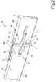
- Fig. 2 is an enlarged view of an end section 5a of the first element 5 and an end section 6a of the second element 6.
- Fig. 2 shows a decorative arrangement 4 according to an embodiment and in an assembled condition, i.e. in a condition in which it is mounted on the support 3 (wherein the support 3 is however not shown in Fig. 2 ).
- the first element 5 has a first end portion 5a and the second element 6 has a second end portion 6a.
- the end portions 5a, 6a are arranged adjacent to each other so that a visual design or symbol 7 - in this case a cross indicating the shap of a flag - is defined when the elements 5, 6 are combined as shown.
- the first end portion 5a has a first thickness t 1 which is less than a second thickness t 2 of a proximate part 5b of the first element 5.
- the first end portion 5a is thinner than the part 5b which is immediately adjacent to said first end portion 5a.
- the second end portion 6a has a third thickness t 3 which is less than a fourth thickness t 4 of a proximate part 6b of the second element 6. Consequently, the second end portion 6a is thinner than the part 6b of the second element 6 which is immediately adjacent to said second end portion 6a.
- the first element 5 and the second element 6 are positioned in relative positions next to each other in a manner so that the second end portion 6a is partly covered by said first end portion 5a when the decorative arrangement 4 is mounted on the support 3.
- the second end portion 6a is positioned behind the first end portion 5a when viewed by an observer.
- first element 5 and the second element 6 are arranged next to each other in a manner so that they define a visual symbol, pattern or design 7 when they are combined together and mounted on the support 3.
- the embodiment shown in Fig. 2 is configured so that the first element 5 and the second element 6 together define a symbol 7 in the shape of a cross, such as a cross which can be part of a design of a flag. This is shown clearly in Fig. 2 .
- a cross is included in the national flags of certain countries (for example Sweden, Denmark and Finland). Designs involving such a flag can for this reason be used in decorative arrangements in order to promote goods being associated with such countries, or trademarks which are related to such countries.
- the shape of the cross, and the entire flag is partly determined by the distance which is created as a result of the first end portion 5a being divided, by means of a gap or recess 8, into a first protrusion 9 and a second protrusion 10.
- the second end portion 5a is formed with a gap 11, or recess, which defines a third protrusion 12 and a fourth protrusion 13 of the second end portion 5a.
- first end section 5a and the second end section 6a can be formed in a suitable manner.
- Such designs include logotypes, letters, numbers, names of companies and persons, trademarks and similar.
- the particular shape of such designs depend on the geometry of the first end portion 5a and the second end portion 6a, and also on the distance between these end portions 5a, 6a when the decorative arrangement 4 is mounted, i.e. the distance indicated as t 5 in Fig. 2 .
- This distance t 5 is defined as a vertically extending space or slot between the edge of the first end portion 5a and the edge of the proximate part 6b of the second element 6.
- This space forms a shape of a cross together with the gaps 8, 11, as shown in Fig. 2 .
- the vertical space defined by the distance t 5 does not necessarily have to be vertical.
- this space may extend in an inclined way, or may be curved or of any other suitable form in order to form part of a desired visual pattern.
- first end portion 5a and the second end portion 6a are not positioned immediately next to each other.
- the distance t 5 absorbs small differences in dimensions of the first and second elements 5, 6 while contributing to the shape of the actual design 7.
- first and second elements 5, 6 have deviations in their dimensions since small variations, approximately 1-2 millimetres, will not be perceived as being unnatural or incorrect when regarding the shape of the cross as shown in Fig. 2 .
- the vertical part of the cross has a width t 5 which may vary depending on the measurements of the first and second elements 5, 6 and also on how much of the tolerances that need to be absorbed. For an observer, there will still be an acceptable visual appearance which gives an impression of quality and precision.
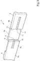
- Fig. 3 corresponds generally to Fig. 2 but shows the first element 5 and the second element 6 in a condition in which they are moved apart, i.e. where they are displaced a certain distance away from each other in their longitudinal direction. Consequently, this corresponds to a non-mounted condition in which the elements 5, 6 are not attached to the support 3.
- the elements 5, 6 may form different types of visual designs depending on the distance between them when they are mounted and also depending on the actual design, dimensions and shape of the first end section 5a and the second end section 6a.
- Fig. 2 also shows that the second end portion 6a will be partly covered by the first end portion 5a when the decorative arrangement 4 is mounted on the support 3 (see Fig. 1 ). In such a mounted condition, the first end portion 5a and the second end portion 6a will be combined together so as to define the visual symbol, pattern or design 7 as described above.
- FIG. 4 An alternative embodiment is shown in Fig. 4 .
- the purpose of this embodiment is to obtain a more clear and distinct representation of the visual design 7, i.e. in this case a flag.
- the first element 5 is provided with a groove 14 which extends across the first element 5 and which consequently defines the shape and design of the first and second protrusions 9, 10 in a more clear and distinct manner.
- the second element 6 is provided with a further groove 15 which defines the shape and design of the third and fourth protrusions 12, 13 in a more clear and distinct manner.
- the surface structure of each rectangle 16, 17, 18, 19 can be formed in a manner which is different from the surface of the remaining parts of the first and second elements 5, 6.
- the surface structure of the rectangles 16, 17, 18, 19 could be manufactured with a particular texture, graining or coating which gives the rectangles 16, 17, 18, 19 a different appearance or structure than the remaining parts of the first and second elements 5, 6.
- Such a texture could be obtained by etching or other methods associated with injection molding of plastic components.
- the rectangles 16, 17, 18, 19 could be covered by a coating in the form of a color, a thin film or a surface structure which renders the surface of the rectangles 16, 17, 18, 19 different from the remaining parts of the first and second elements 5, 6.
- the inventive concept is not limited to use in vehicles such as a car, but can be implemented in other types of vehicles too, for example trucks and buses.
- vehicles can be used in both exterior and interior decorative arrangements, i.e. running boards and strips mounted on exterior and interior supports on a vehicle.
Landscapes
- Engineering & Computer Science (AREA)
- Mechanical Engineering (AREA)
- Vehicle Interior And Exterior Ornaments, Soundproofing, And Insulation (AREA)
Abstract
Description
- The invention relates to a decorative arrangement for mounting on a support and comprising a first element and a second element configured for being arranged next to each other so as to define a visual symbol, pattern or design.
- The invention can be used for different types of decorative purposes in the automotive industry, for example in interior or exterior arrangements of decorative strips and similar elements in vehicles. The invention is not limited to the field of vehicles, but can be applied in various fields of technology where a decorative arrangement comprising at least two different elements are mounted next to each other.
- In various fields of industry, for example in the field of vehicles, there is a general need to provide decorative parts so as to be mounted on various types of support elements. It is of high importance that such decorative parts have accurate measurements and shape in order to give an impression of precision, fit and quality when these parts are mounted on their support elements.
- With regard to decorative arrangements such as strips, linings and panels which are mounted on vehicles, i.e. either on interior or exterior parts of vehicles, it is of particular importance that such arrangements are manufactured with a high level of accuracy, fit and precision. For example, it is important that the measurements of the element in question does not deviate from pre-set, nominal measurements, including certain tolerances.
- However, even if the manufacturing of such parts as mentioned above is carried out with a high level of accuracy and within acceptable tolerances, there are always some slight variations in measurements and fit between each individual element. This is due to imperfections during various manufacturing processes, deviations in materials, temperature variations during manufacturing and many other reasons.
- As an example, an arrangement of decorative strips or linings which are used in a vehicle may be manufactured and then mounted in the form of two or more separate pieces. When mounting such a decorative arrangement, for example with two separate strip elements next to each other, there will be a split or slight gap between the two elements. Even though it can be expected that the elements have been manufactured with accurate measurements and within certain tolerances, such a gap can in most practical cases not be zero. This means that there will be a narrow, but still visible, gap between the two elements. Such a visible gap may give an observer or user an impression of low precision and inferior quality of the decorative arrangement.
- Also, due to the above-mentioned slight variations in measurement and shape, this split or gap may be of different magnitude. In the unlucky event that the gap is relatively large, an observer may obviously get an impression that the decorative arrangement is of low quality. Such an impression may influence a user, or potential buyer of the vehicle, in a negative direction.
- In summary, it is known that the perceived appearance of a decorative arrangement by an observer - and as a result the perceived quality of the entire interior of the vehicle - can be affected in a negative way due to deviations of such arrangements from their nominal, expected measurements and shapes. As a result, the user may get an impression of low quality and poor precision, which obviously is a problem.
- The above-mentioned situation is based on the visual perception that an observer gets from variations in geometry and measurements of a decorative arrangement. In the automotive industry, for example, the subjective appearance of certain visible parts, such as decorative parts, is crucial in order for a user and a potential vehicle buyer to get an overall impression of quality and precision. This means that such parts must be manufactured and mounted in a manner wherein the risk for being visually perceived as being of low quality is minimized. The visual impression that a user gets is relevant for example in a situation where two components are situated next to each other, i.e. where a gap or split is created as explained above.
- The patent document
DE 10025360 teaches a decorative strip for interior use in a vehicle. The decorative strip comprises an upper strip with a decorative outer surface and which fits into a recess in a lower strip. Consequently, it is previously known to mount a an upper vehicle decorative strip into a lower decorative strip of different material, in a recess, so as to provide a flat transition between the two parts. - Even though there exist solutions to the problem of minimizing gaps and dividing lines between two adjacent elements, there is still need for improved devices and methods for providing decorative arrangements which may combine two different decorative elements in a flawless manner. In particular, there is a need to obtain decorative arrangements giving a visual impression of precision and high quality for an observer.
- Consequently, an object of the invention is to provide an improved decorative arrangement which solves the above-mentioned problems associated with previous solutions and which offers a cost-effective and accurate decorative arrangement forming a visual design or pattern and giving the viewer an impression of high quality and precision.
- The above-mentioned object is achieved by a decorative arrangement for mounting on a support and comprising a first element and a second element configured for being arranged next to each other so as to define a visual symbol, pattern or design. Furthermore, the first element comprises a first end portion having a first thickness which is less than a second thickness of a proximate part of the first element; and the second element comprises a second end portion having a third thickness which is less than a fourth thickness of a proximate part of the second element; said second end portion being partly covered by said first end portion when the decorative arrangement is mounted on said support; wherein the first end portion and the second end portion are arranged to define, when combined together, said visual symbol, pattern or design.
- The invention provides certain advantages over previously known technology, primarily due to the fact that it allows deviations in measurements and shape of the first and second element to be absorbed by the shape of said visual symbol, pattern or design without the decorative arrangement being perceived as being of inferior quality or low precision by an observer. Also, the first and second elements can be manufactured within certain tolerances without any risk for an inacceptable visual appearance when mounted. The arrangement according to the invention is consequently not "visually sensitive", i.e. it will not create a visual appearance leading to a perceived low quality.
- According to an embodiment, the first end portion and said second end portion of the decorative arrangement are shaped so as to define the design of a cross when mounted. Due to the fact that a cross is part of the flags or certain countries, this means that the arrangement can be used for example for promoting goods being associated with countries having certain national flags.
- According to an embodiment, a distance is defined between the respective ends of the first end portion and the proximate part of the second element. This distance is defined by a displacement of the first element and the second element in their longitudinal direction, and furthermore defines a space forming part of said visual symbol, pattern or design. This allows a high degree of flexibility in forming a suitable visual symbol, pattern or design.
- According to an embodiment, each of the first element and the second element is formed with a groove extending across said first element. These grooves delimite the visual symbol, pattern or design, thereby making it appear visually more clearly and distinctly.
- Also, according to an embodiment, the first end portion and second end portion at least partly have a surface structure which differs from that of the remaining first and second elements. This makes the visual symbol, pattern or design appear visually more clearly against the remaining parts of the arrangement.
- The invention can be applied in different types of vehicles, such as cars, trucks, and buses. Although the invention will be described with respect to an application in the form of a conventional car, the invention is not restricted to this particular vehicle only. Generally, the invention can also be used in other applications than vehicles.
- Further advantages and advantageous features of the invention are disclosed in the following description and in the dependent claims.
- Further objects, features, and advantages of the present disclosure will appear from the following detailed description, wherein certain aspects of the disclosure will be described in more detail with reference to the accompanying drawings, in which:
- Fig. 1
- shows a perspective view of an interior of a vehicle with a decorative arrangement comprising a first element and a second element, according to a first embodiment.
- Fig. 2
- is an enlarged view of a part of an embodiment of the decorative arrangement, in a condition in which it is mounted on a support.
- Fig. 3
- is an enlarged view corresponding to
Fig. 2 but when shows the decorative arrangement in a condition in which the first element and the second element are separated. - Fig. 4
- is a view corresponding to
Fig. 2 but showing an alternative embodiment. - Different embodiments of the present invention will now be described with reference to the accompanying drawings. The arrangements described below and defined in the appended claims can be realized in different forms and should not be construed as being limited to the embodiments described below.
- With initial reference to
Fig. 1 , there is shown a perspective view of a front part of acompartment 1 of a vehicle, for example in the form of a conventional car. Thevehicle compartment 1 comprises adashboard 2 which is arranged in a generally conventional manner. Thedashboard 2 comprises asupport surface 3 which supports adecorative arrangement 4 which extends along generally theentire dashboard 2, i.e. transverse to the longitudinal extension of the vehicle in question. - According to an embodiment, the
decorative arrangement 4 is constituted by an set of relatively thin decorative strips being manufactured from a suitable plastic material such as polyvinyl chloride (PVC) having a chrome surface finish. The decorative strips can be manufactured for example by means of an extrusion molding arrangement. Such a manufacturing process is previously known as such, and for this reason it is not described in detail here. Strips and linings of various types and of such material and surface finish as mentioned above are previously known and are often used in the automotive industry. The actual surface finish, colour, material and design of thedecorative arrangement 4 can be varied within the scope of the invention. - According to the embodiment shown in
Fig. 1 , thedecorative arrangement 4 is constituted by a firstdecorative element 5 and a seconddecorative element 6 which are configured so as to be arranged next to each other when thecomplete arrangement 4 is mounted on thesupport surface 3. More precisely, the seconddecorative element 6 is arranged as an extension of the firstdecorative element 5 in its longitudinal direction. - According to the embodiment, the
decorative arrangement 4 is split into the twodecorative elements decorative arrangement 4 into two or more strips instead of using one single element. For example, the manufacturing process for the decorative strips may result in variations in length of said strips. Also, the length of the decorative strips may vary depending on the temperature, in particular when they are mounted on thesupport surface 3. For these reasons, thedecorative arrangement 4 as shown inFig. 1 is divided into two elements, allowing variations in length to be absorbed by mounting theelements first element 5 is positioned in the left part in the drawing and thesecond element 6 is positioned in the right part of the drawing, so that the end portions of theelements decorative arrangement 4 which corresponds to a visual symbol, pattern ordesign 7. InFig. 1 , this visual symbol is in the form of a cross, which can be used as a part of a symbol for a flag. Consequently, thissymbol 7 is formed as a result of thefirst element 5 and thesecond element 6 being combined together by being positioned next to each other. This is shown in greater detail inFig. 2 , which is an enlarged view of anend section 5a of thefirst element 5 and anend section 6a of thesecond element 6. -
Fig. 2 shows adecorative arrangement 4 according to an embodiment and in an assembled condition, i.e. in a condition in which it is mounted on the support 3 (wherein thesupport 3 is however not shown inFig. 2 ). According to the embodiment, thefirst element 5 has afirst end portion 5a and thesecond element 6 has asecond end portion 6a. Theend portions elements first end portion 5a has a first thickness t1 which is less than a second thickness t2 of aproximate part 5b of thefirst element 5. In other words, thefirst end portion 5a is thinner than thepart 5b which is immediately adjacent to saidfirst end portion 5a. - Also, in a corresponding manner, the
second end portion 6a has a third thickness t3 which is less than a fourth thickness t4 of aproximate part 6b of thesecond element 6. Consequently, thesecond end portion 6a is thinner than thepart 6b of thesecond element 6 which is immediately adjacent to saidsecond end portion 6a. - Furthermore, and as shown in
Fig. 2 , thefirst element 5 and thesecond element 6 are positioned in relative positions next to each other in a manner so that thesecond end portion 6a is partly covered by saidfirst end portion 5a when thedecorative arrangement 4 is mounted on thesupport 3. In other words, thesecond end portion 6a is positioned behind thefirst end portion 5a when viewed by an observer. - As mentioned above, the
first element 5 and thesecond element 6 are arranged next to each other in a manner so that they define a visual symbol, pattern ordesign 7 when they are combined together and mounted on thesupport 3. The embodiment shown inFig. 2 is configured so that thefirst element 5 and thesecond element 6 together define asymbol 7 in the shape of a cross, such as a cross which can be part of a design of a flag. This is shown clearly inFig. 2 . Such a cross is included in the national flags of certain countries (for example Sweden, Denmark and Finland). Designs involving such a flag can for this reason be used in decorative arrangements in order to promote goods being associated with such countries, or trademarks which are related to such countries. - It should be noted that the shape of the cross, and the entire flag, is partly determined by the distance which is created as a result of the
first end portion 5a being divided, by means of a gap orrecess 8, into afirst protrusion 9 and asecond protrusion 10. In a corresponding manner, thesecond end portion 5a is formed with agap 11, or recess, which defines athird protrusion 12 and afourth protrusion 13 of thesecond end portion 5a. - According to alternative embodiments, other forms of visual patterns and designs can be provided by forming the
first end section 5a and thesecond end section 6a in a suitable manner. Such designs include logotypes, letters, numbers, names of companies and persons, trademarks and similar. The particular shape of such designs depend on the geometry of thefirst end portion 5a and thesecond end portion 6a, and also on the distance between theseend portions decorative arrangement 4 is mounted, i.e. the distance indicated as t5 inFig. 2 . This distance t5 is defined as a vertically extending space or slot between the edge of thefirst end portion 5a and the edge of theproximate part 6b of thesecond element 6. This space forms a shape of a cross together with thegaps Fig. 2 . - According to further embodiments, the vertical space defined by the distance t5 does not necessarily have to be vertical. In fact, this space may extend in an inclined way, or may be curved or of any other suitable form in order to form part of a desired visual pattern.
- An important feature of the invention is that the
first end portion 5a and thesecond end portion 6a are not positioned immediately next to each other. In fact, the distance t5 absorbs small differences in dimensions of the first andsecond elements actual design 7. For an observer, it will not be apparent if the first andsecond elements Fig. 2 . - Consequently, the vertical part of the cross has a width t5 which may vary depending on the measurements of the first and
second elements -
Fig. 3 corresponds generally toFig. 2 but shows thefirst element 5 and thesecond element 6 in a condition in which they are moved apart, i.e. where they are displaced a certain distance away from each other in their longitudinal direction. Consequently, this corresponds to a non-mounted condition in which theelements support 3. It is apparent fromFig. 3 that theelements first end section 5a and thesecond end section 6a.Fig. 2 also shows that thesecond end portion 6a will be partly covered by thefirst end portion 5a when thedecorative arrangement 4 is mounted on the support 3 (seeFig. 1 ). In such a mounted condition, thefirst end portion 5a and thesecond end portion 6a will be combined together so as to define the visual symbol, pattern ordesign 7 as described above. - An alternative embodiment is shown in
Fig. 4 . The purpose of this embodiment is to obtain a more clear and distinct representation of thevisual design 7, i.e. in this case a flag. To this end, thefirst element 5 is provided with agroove 14 which extends across thefirst element 5 and which consequently defines the shape and design of the first andsecond protrusions second element 6 is provided with afurther groove 15 which defines the shape and design of the third andfourth protrusions - This means that a visual design of a flag will be more clear and accurate by using the
grooves first element 5 andsecond element 6, respectively. The actual positions of thegrooves recesses decorative arrangement 4. More precisely, the fourprotrusions first end element 5a and thesecond end element 6a will define (together with thegrooves 14, 15) fourrectangles - According to an embodiment, the surface structure of each
rectangle second elements rectangles rectangles second elements rectangles rectangles second elements - In summary, by providing a surface structure of the
rectangles decorative arrangement 4, the visual design in question will appear more clearly and distinct to an observer. - It is to be understood that the present invention is not limited to the embodiments described above and illustrated in the drawings. The skilled person will recognize that changes and modifications may be made within the scope of the appended claims.
- For example, the inventive concept is not limited to use in vehicles such as a car, but can be implemented in other types of vehicles too, for example trucks and buses. In case it is implemented in vehicles, it can be used in both exterior and interior decorative arrangements, i.e. running boards and strips mounted on exterior and interior supports on a vehicle.
Claims (7)
- Decorative arrangement (4) for mounting on a support (3) and comprising a first element (5) and a second element (6) configured for being arranged next to each other so as to define a visual symbol, pattern or design (7);
characterized in that- the first element (5) comprises a first end portion (5a) having a first thickness (t1) which is less than a second thickness (t2) of a proximate part (5b) of the first element (5); and- the second element (6) comprises a second end portion (6a) having a third thickness (t3) which is less than a fourth thickness (t4) of a proximate part (6b) of the second element (6);- said second end portion (6a) being partly covered by said first end portion (5a) when the decorative arrangement (4) is mounted on said support (3); wherein- the first end portion (5a) and the second end portion (6a) are arranged to define, when combined together, said visual symbol, pattern or design (7). - Decorative arrangement (4) according to claim 1, wherein said first end portion (5a) and said second end portion (5b) are shaped so as to define the design of a cross when mounted.
- Decorative arrangement (4) according to claim 1 or 2, wherein said first end portion (5a) has a recess (8) and the second end portion has a recess (11) which form part of said visual symbol, pattern or design (7).
- Decorative arrangement (4) according to any one of the preceding claims, wherein a distance (t5) between the respective ends of the first end portion (5a) and the proximate part (6b) of the second element (6), defined by a displacement of the first element (5) and the second element (6) in their longitudinal direction, defines a space forming part of said visual symbol, pattern or design (7).
- Decorative arrangement (4) according to any one of the preceding claims, wherein said first element (5) is formed with a groove (14) extending across the first element (5), and said second element (6) is formed with a further groove (15) extending across the second element (6), said grooves (14, 15) delimiting said visual symbol, pattern or design, thereby making it appear visually more clearly and distinctly.
- Decorative arrangement (4) according to any one of the preceding claims, wherein said first end portion (5a) and said second end portion (6a) at least partly have a surface structure which differs from that of the remaining first and second elements (5, 6).
- Decorative arrangement (4) according to claim 6, wherein said surface structure is formed by means of etching or by means of a surface coating.
Priority Applications (1)
| Application Number | Priority Date | Filing Date | Title |
|---|---|---|---|
| EP15196468.1A EP3173291B1 (en) | 2015-11-26 | 2015-11-26 | Tolerance gap flag |
Applications Claiming Priority (1)
| Application Number | Priority Date | Filing Date | Title |
|---|---|---|---|
| EP15196468.1A EP3173291B1 (en) | 2015-11-26 | 2015-11-26 | Tolerance gap flag |
Publications (2)
| Publication Number | Publication Date |
|---|---|
| EP3173291A1 true EP3173291A1 (en) | 2017-05-31 |
| EP3173291B1 EP3173291B1 (en) | 2018-06-20 |
Family
ID=54707599
Family Applications (1)
| Application Number | Title | Priority Date | Filing Date |
|---|---|---|---|
| EP15196468.1A Active EP3173291B1 (en) | 2015-11-26 | 2015-11-26 | Tolerance gap flag |
Country Status (1)
| Country | Link |
|---|---|
| EP (1) | EP3173291B1 (en) |
Cited By (2)
| Publication number | Priority date | Publication date | Assignee | Title |
|---|---|---|---|---|
| WO2022242937A1 (en) * | 2021-05-18 | 2022-11-24 | Psa Automobiles Sa | Trim device for a vehicle, and vehicle body of a vehicle |
| WO2022242938A1 (en) * | 2021-05-17 | 2022-11-24 | Psa Automobiles Sa | Motor vehicle component having a decorative element |
Citations (3)
| Publication number | Priority date | Publication date | Assignee | Title |
|---|---|---|---|---|
| DE10025360C1 (en) | 2000-05-23 | 2001-10-25 | Draexlmaier Lisa Gmbh | Decorative strip for internal use in cars comprises upper strip with decorative outer surface which fits into recess in lower strip, inside upwardly-sloping outer section with different decorative outer surface |
| WO2002031290A1 (en) * | 2000-10-12 | 2002-04-18 | Josef Hrovath | Tile |
| JP2007198098A (en) * | 2006-01-30 | 2007-08-09 | Kubota Matsushitadenko Exterior Works Ltd | Decorative panels for building |
-
2015
- 2015-11-26 EP EP15196468.1A patent/EP3173291B1/en active Active
Patent Citations (3)
| Publication number | Priority date | Publication date | Assignee | Title |
|---|---|---|---|---|
| DE10025360C1 (en) | 2000-05-23 | 2001-10-25 | Draexlmaier Lisa Gmbh | Decorative strip for internal use in cars comprises upper strip with decorative outer surface which fits into recess in lower strip, inside upwardly-sloping outer section with different decorative outer surface |
| WO2002031290A1 (en) * | 2000-10-12 | 2002-04-18 | Josef Hrovath | Tile |
| JP2007198098A (en) * | 2006-01-30 | 2007-08-09 | Kubota Matsushitadenko Exterior Works Ltd | Decorative panels for building |
Cited By (2)
| Publication number | Priority date | Publication date | Assignee | Title |
|---|---|---|---|---|
| WO2022242938A1 (en) * | 2021-05-17 | 2022-11-24 | Psa Automobiles Sa | Motor vehicle component having a decorative element |
| WO2022242937A1 (en) * | 2021-05-18 | 2022-11-24 | Psa Automobiles Sa | Trim device for a vehicle, and vehicle body of a vehicle |
Also Published As
| Publication number | Publication date |
|---|---|
| EP3173291B1 (en) | 2018-06-20 |
Similar Documents
| Publication | Publication Date | Title |
|---|---|---|
| JPWO2009154008A1 (en) | Pneumatic tire | |
| CN109416899B (en) | Display element with partially filmed and painted transition mask | |
| DE102007052849A1 (en) | Partially chrome-plated device and method for its production | |
| EP3173291B1 (en) | Tolerance gap flag | |
| WO2019162268A1 (en) | Shaped part and method for producing a shaped part | |
| DE102020005896A1 (en) | Process for producing a flat paneling element for a vehicle | |
| WO2005009795A2 (en) | Decorative trim part | |
| CN105083151A (en) | Rear Loaded Interior Badge | |
| DE112014005403T5 (en) | Scaling wheel with radial lines and motor vehicle display with scale disk with radial lines | |
| US6454422B1 (en) | Backlit indicia on a painted surface | |
| US9738157B1 (en) | Decorative part for vehicle display device and vehicle display device | |
| DE102017120152A1 (en) | Visible part in particular for an operating element in a motor vehicle | |
| DE102018005592A1 (en) | radome | |
| EP3245102B1 (en) | Decorative trim for a motor vehicle | |
| JP5103920B2 (en) | Method for manufacturing instrument display board | |
| US10576883B2 (en) | Dial gauge with chaplet tick mark illumination | |
| US20040055193A1 (en) | Backlit sign | |
| CN223290797U (en) | Decorative panels for vehicles | |
| JPH10323858A (en) | Method for producing plastic shell and bezel | |
| US11226216B2 (en) | Self adjusting retention feature for applique assembly | |
| JPS638022A (en) | Manufacturing method of automotive window molding | |
| US10836328B2 (en) | Vehicle upholstery member | |
| JP6160981B2 (en) | Instrument manufacturing method | |
| JP5441592B2 (en) | Metallic decorative parts for vehicles and manufacturing method thereof | |
| JP7142413B2 (en) | Resin panel part and its manufacturing method |
Legal Events
| Date | Code | Title | Description |
|---|---|---|---|
| PUAI | Public reference made under article 153(3) epc to a published international application that has entered the european phase |
Free format text: ORIGINAL CODE: 0009012 |
|
| AK | Designated contracting states |
Kind code of ref document: A1 Designated state(s): AL AT BE BG CH CY CZ DE DK EE ES FI FR GB GR HR HU IE IS IT LI LT LU LV MC MK MT NL NO PL PT RO RS SE SI SK SM TR |
|
| AX | Request for extension of the european patent |
Extension state: BA ME |
|
| 17P | Request for examination filed |
Effective date: 20171130 |
|
| RBV | Designated contracting states (corrected) |
Designated state(s): AL AT BE BG CH CY CZ DE DK EE ES FI FR GB GR HR HU IE IS IT LI LT LU LV MC MK MT NL NO PL PT RO RS SE SI SK SM TR |
|
| GRAP | Despatch of communication of intention to grant a patent |
Free format text: ORIGINAL CODE: EPIDOSNIGR1 |
|
| INTG | Intention to grant announced |
Effective date: 20180202 |
|
| GRAS | Grant fee paid |
Free format text: ORIGINAL CODE: EPIDOSNIGR3 |
|
| GRAA | (expected) grant |
Free format text: ORIGINAL CODE: 0009210 |
|
| AK | Designated contracting states |
Kind code of ref document: B1 Designated state(s): AL AT BE BG CH CY CZ DE DK EE ES FI FR GB GR HR HU IE IS IT LI LT LU LV MC MK MT NL NO PL PT RO RS SE SI SK SM TR |
|
| REG | Reference to a national code |
Ref country code: GB Ref legal event code: FG4D |
|
| REG | Reference to a national code |
Ref country code: IE Ref legal event code: FG4D |
|
| REG | Reference to a national code |
Ref country code: AT Ref legal event code: REF Ref document number: 1010350 Country of ref document: AT Kind code of ref document: T Effective date: 20180715 |
|
| REG | Reference to a national code |
Ref country code: DE Ref legal event code: R096 Ref document number: 602015012475 Country of ref document: DE |
|
| REG | Reference to a national code |
Ref country code: SE Ref legal event code: TRGR |
|
| REG | Reference to a national code |
Ref country code: NL Ref legal event code: MP Effective date: 20180620 |
|
| PG25 | Lapsed in a contracting state [announced via postgrant information from national office to epo] |
Ref country code: NO Free format text: LAPSE BECAUSE OF FAILURE TO SUBMIT A TRANSLATION OF THE DESCRIPTION OR TO PAY THE FEE WITHIN THE PRESCRIBED TIME-LIMIT Effective date: 20180920 Ref country code: FI Free format text: LAPSE BECAUSE OF FAILURE TO SUBMIT A TRANSLATION OF THE DESCRIPTION OR TO PAY THE FEE WITHIN THE PRESCRIBED TIME-LIMIT Effective date: 20180620 Ref country code: BG Free format text: LAPSE BECAUSE OF FAILURE TO SUBMIT A TRANSLATION OF THE DESCRIPTION OR TO PAY THE FEE WITHIN THE PRESCRIBED TIME-LIMIT Effective date: 20180920 Ref country code: LT Free format text: LAPSE BECAUSE OF FAILURE TO SUBMIT A TRANSLATION OF THE DESCRIPTION OR TO PAY THE FEE WITHIN THE PRESCRIBED TIME-LIMIT Effective date: 20180620 |
|
| REG | Reference to a national code |
Ref country code: LT Ref legal event code: MG4D |
|
| PG25 | Lapsed in a contracting state [announced via postgrant information from national office to epo] |
Ref country code: LV Free format text: LAPSE BECAUSE OF FAILURE TO SUBMIT A TRANSLATION OF THE DESCRIPTION OR TO PAY THE FEE WITHIN THE PRESCRIBED TIME-LIMIT Effective date: 20180620 Ref country code: HR Free format text: LAPSE BECAUSE OF FAILURE TO SUBMIT A TRANSLATION OF THE DESCRIPTION OR TO PAY THE FEE WITHIN THE PRESCRIBED TIME-LIMIT Effective date: 20180620 Ref country code: GR Free format text: LAPSE BECAUSE OF FAILURE TO SUBMIT A TRANSLATION OF THE DESCRIPTION OR TO PAY THE FEE WITHIN THE PRESCRIBED TIME-LIMIT Effective date: 20180921 Ref country code: RS Free format text: LAPSE BECAUSE OF FAILURE TO SUBMIT A TRANSLATION OF THE DESCRIPTION OR TO PAY THE FEE WITHIN THE PRESCRIBED TIME-LIMIT Effective date: 20180620 |
|
| REG | Reference to a national code |
Ref country code: AT Ref legal event code: MK05 Ref document number: 1010350 Country of ref document: AT Kind code of ref document: T Effective date: 20180620 |
|
| PG25 | Lapsed in a contracting state [announced via postgrant information from national office to epo] |
Ref country code: NL Free format text: LAPSE BECAUSE OF FAILURE TO SUBMIT A TRANSLATION OF THE DESCRIPTION OR TO PAY THE FEE WITHIN THE PRESCRIBED TIME-LIMIT Effective date: 20180620 |
|
| PG25 | Lapsed in a contracting state [announced via postgrant information from national office to epo] |
Ref country code: IS Free format text: LAPSE BECAUSE OF FAILURE TO SUBMIT A TRANSLATION OF THE DESCRIPTION OR TO PAY THE FEE WITHIN THE PRESCRIBED TIME-LIMIT Effective date: 20181020 Ref country code: AT Free format text: LAPSE BECAUSE OF FAILURE TO SUBMIT A TRANSLATION OF THE DESCRIPTION OR TO PAY THE FEE WITHIN THE PRESCRIBED TIME-LIMIT Effective date: 20180620 Ref country code: EE Free format text: LAPSE BECAUSE OF FAILURE TO SUBMIT A TRANSLATION OF THE DESCRIPTION OR TO PAY THE FEE WITHIN THE PRESCRIBED TIME-LIMIT Effective date: 20180620 Ref country code: PL Free format text: LAPSE BECAUSE OF FAILURE TO SUBMIT A TRANSLATION OF THE DESCRIPTION OR TO PAY THE FEE WITHIN THE PRESCRIBED TIME-LIMIT Effective date: 20180620 Ref country code: RO Free format text: LAPSE BECAUSE OF FAILURE TO SUBMIT A TRANSLATION OF THE DESCRIPTION OR TO PAY THE FEE WITHIN THE PRESCRIBED TIME-LIMIT Effective date: 20180620 Ref country code: CZ Free format text: LAPSE BECAUSE OF FAILURE TO SUBMIT A TRANSLATION OF THE DESCRIPTION OR TO PAY THE FEE WITHIN THE PRESCRIBED TIME-LIMIT Effective date: 20180620 Ref country code: SK Free format text: LAPSE BECAUSE OF FAILURE TO SUBMIT A TRANSLATION OF THE DESCRIPTION OR TO PAY THE FEE WITHIN THE PRESCRIBED TIME-LIMIT Effective date: 20180620 |
|
| PGFP | Annual fee paid to national office [announced via postgrant information from national office to epo] |
Ref country code: SE Payment date: 20181116 Year of fee payment: 4 |
|
| PG25 | Lapsed in a contracting state [announced via postgrant information from national office to epo] |
Ref country code: IT Free format text: LAPSE BECAUSE OF FAILURE TO SUBMIT A TRANSLATION OF THE DESCRIPTION OR TO PAY THE FEE WITHIN THE PRESCRIBED TIME-LIMIT Effective date: 20180620 Ref country code: SM Free format text: LAPSE BECAUSE OF FAILURE TO SUBMIT A TRANSLATION OF THE DESCRIPTION OR TO PAY THE FEE WITHIN THE PRESCRIBED TIME-LIMIT Effective date: 20180620 Ref country code: ES Free format text: LAPSE BECAUSE OF FAILURE TO SUBMIT A TRANSLATION OF THE DESCRIPTION OR TO PAY THE FEE WITHIN THE PRESCRIBED TIME-LIMIT Effective date: 20180620 |
|
| REG | Reference to a national code |
Ref country code: DE Ref legal event code: R097 Ref document number: 602015012475 Country of ref document: DE |
|
| PLBE | No opposition filed within time limit |
Free format text: ORIGINAL CODE: 0009261 |
|
| STAA | Information on the status of an ep patent application or granted ep patent |
Free format text: STATUS: NO OPPOSITION FILED WITHIN TIME LIMIT |
|
| 26N | No opposition filed |
Effective date: 20190321 |
|
| PG25 | Lapsed in a contracting state [announced via postgrant information from national office to epo] |
Ref country code: DK Free format text: LAPSE BECAUSE OF FAILURE TO SUBMIT A TRANSLATION OF THE DESCRIPTION OR TO PAY THE FEE WITHIN THE PRESCRIBED TIME-LIMIT Effective date: 20180620 |
|
| REG | Reference to a national code |
Ref country code: CH Ref legal event code: PL |
|
| PG25 | Lapsed in a contracting state [announced via postgrant information from national office to epo] |
Ref country code: LU Free format text: LAPSE BECAUSE OF NON-PAYMENT OF DUE FEES Effective date: 20181126 Ref country code: MC Free format text: LAPSE BECAUSE OF FAILURE TO SUBMIT A TRANSLATION OF THE DESCRIPTION OR TO PAY THE FEE WITHIN THE PRESCRIBED TIME-LIMIT Effective date: 20180620 |
|
| REG | Reference to a national code |
Ref country code: BE Ref legal event code: MM Effective date: 20181130 |
|
| REG | Reference to a national code |
Ref country code: IE Ref legal event code: MM4A |
|
| PG25 | Lapsed in a contracting state [announced via postgrant information from national office to epo] |
Ref country code: LI Free format text: LAPSE BECAUSE OF NON-PAYMENT OF DUE FEES Effective date: 20181130 Ref country code: CH Free format text: LAPSE BECAUSE OF NON-PAYMENT OF DUE FEES Effective date: 20181130 Ref country code: SI Free format text: LAPSE BECAUSE OF FAILURE TO SUBMIT A TRANSLATION OF THE DESCRIPTION OR TO PAY THE FEE WITHIN THE PRESCRIBED TIME-LIMIT Effective date: 20180620 |
|
| PG25 | Lapsed in a contracting state [announced via postgrant information from national office to epo] |
Ref country code: IE Free format text: LAPSE BECAUSE OF NON-PAYMENT OF DUE FEES Effective date: 20181126 Ref country code: FR Free format text: LAPSE BECAUSE OF NON-PAYMENT OF DUE FEES Effective date: 20181130 |
|
| PG25 | Lapsed in a contracting state [announced via postgrant information from national office to epo] |
Ref country code: AL Free format text: LAPSE BECAUSE OF FAILURE TO SUBMIT A TRANSLATION OF THE DESCRIPTION OR TO PAY THE FEE WITHIN THE PRESCRIBED TIME-LIMIT Effective date: 20180620 Ref country code: BE Free format text: LAPSE BECAUSE OF NON-PAYMENT OF DUE FEES Effective date: 20181130 |
|
| PG25 | Lapsed in a contracting state [announced via postgrant information from national office to epo] |
Ref country code: MT Free format text: LAPSE BECAUSE OF NON-PAYMENT OF DUE FEES Effective date: 20181126 |
|
| PG25 | Lapsed in a contracting state [announced via postgrant information from national office to epo] |
Ref country code: TR Free format text: LAPSE BECAUSE OF FAILURE TO SUBMIT A TRANSLATION OF THE DESCRIPTION OR TO PAY THE FEE WITHIN THE PRESCRIBED TIME-LIMIT Effective date: 20180620 |
|
| PG25 | Lapsed in a contracting state [announced via postgrant information from national office to epo] |
Ref country code: PT Free format text: LAPSE BECAUSE OF FAILURE TO SUBMIT A TRANSLATION OF THE DESCRIPTION OR TO PAY THE FEE WITHIN THE PRESCRIBED TIME-LIMIT Effective date: 20180620 |
|
| PG25 | Lapsed in a contracting state [announced via postgrant information from national office to epo] |
Ref country code: HU Free format text: LAPSE BECAUSE OF FAILURE TO SUBMIT A TRANSLATION OF THE DESCRIPTION OR TO PAY THE FEE WITHIN THE PRESCRIBED TIME-LIMIT; INVALID AB INITIO Effective date: 20151126 Ref country code: CY Free format text: LAPSE BECAUSE OF FAILURE TO SUBMIT A TRANSLATION OF THE DESCRIPTION OR TO PAY THE FEE WITHIN THE PRESCRIBED TIME-LIMIT Effective date: 20180620 Ref country code: MK Free format text: LAPSE BECAUSE OF NON-PAYMENT OF DUE FEES Effective date: 20180620 |
|
| REG | Reference to a national code |
Ref country code: SE Ref legal event code: EUG |
|
| PG25 | Lapsed in a contracting state [announced via postgrant information from national office to epo] |
Ref country code: SE Free format text: LAPSE BECAUSE OF NON-PAYMENT OF DUE FEES Effective date: 20191127 |
|
| GBPC | Gb: european patent ceased through non-payment of renewal fee |
Effective date: 20191126 |
|
| PG25 | Lapsed in a contracting state [announced via postgrant information from national office to epo] |
Ref country code: GB Free format text: LAPSE BECAUSE OF NON-PAYMENT OF DUE FEES Effective date: 20191126 |
|
| P01 | Opt-out of the competence of the unified patent court (upc) registered |
Effective date: 20231212 |
|
| PGFP | Annual fee paid to national office [announced via postgrant information from national office to epo] |
Ref country code: DE Payment date: 20251022 Year of fee payment: 11 |