EP3173207A1 - Injection unit and direction changeover valve - Google Patents
Injection unit and direction changeover valve Download PDFInfo
- Publication number
- EP3173207A1 EP3173207A1 EP16198332.5A EP16198332A EP3173207A1 EP 3173207 A1 EP3173207 A1 EP 3173207A1 EP 16198332 A EP16198332 A EP 16198332A EP 3173207 A1 EP3173207 A1 EP 3173207A1
- Authority
- EP
- European Patent Office
- Prior art keywords
- connection port
- cylinder
- valve body
- plug portion
- communicates
- Prior art date
- Legal status (The legal status is an assumption and is not a legal conclusion. Google has not performed a legal analysis and makes no representation as to the accuracy of the status listed.)
- Granted
Links
- 238000002347 injection Methods 0.000 title claims abstract description 24
- 239000007924 injection Substances 0.000 title claims abstract description 24
- 239000012778 molding material Substances 0.000 claims abstract description 39
- 238000005192 partition Methods 0.000 claims description 12
- 239000012530 fluid Substances 0.000 claims description 3
- 238000004891 communication Methods 0.000 description 9
- 238000000034 method Methods 0.000 description 9
- 238000005429 filling process Methods 0.000 description 6
- 230000003247 decreasing effect Effects 0.000 description 5
- 239000007788 liquid Substances 0.000 description 5
- 230000004048 modification Effects 0.000 description 5
- 238000012986 modification Methods 0.000 description 5
- 238000000465 moulding Methods 0.000 description 5
- 238000006243 chemical reaction Methods 0.000 description 4
- 238000001746 injection moulding Methods 0.000 description 3
- 239000007787 solid Substances 0.000 description 3
- 238000010438 heat treatment Methods 0.000 description 2
- 230000008021 deposition Effects 0.000 description 1
- 239000000155 melt Substances 0.000 description 1
- 239000011347 resin Substances 0.000 description 1
- 229920005989 resin Polymers 0.000 description 1
Images


Classifications
-
- B—PERFORMING OPERATIONS; TRANSPORTING
- B29—WORKING OF PLASTICS; WORKING OF SUBSTANCES IN A PLASTIC STATE IN GENERAL
- B29C—SHAPING OR JOINING OF PLASTICS; SHAPING OF MATERIAL IN A PLASTIC STATE, NOT OTHERWISE PROVIDED FOR; AFTER-TREATMENT OF THE SHAPED PRODUCTS, e.g. REPAIRING
- B29C45/00—Injection moulding, i.e. forcing the required volume of moulding material through a nozzle into a closed mould; Apparatus therefor
- B29C45/17—Component parts, details or accessories; Auxiliary operations
- B29C45/46—Means for plasticising or homogenising the moulding material or forcing it into the mould
- B29C45/53—Means for plasticising or homogenising the moulding material or forcing it into the mould using injection ram or piston
- B29C45/54—Means for plasticising or homogenising the moulding material or forcing it into the mould using injection ram or piston and plasticising screw
-
- B—PERFORMING OPERATIONS; TRANSPORTING
- B29—WORKING OF PLASTICS; WORKING OF SUBSTANCES IN A PLASTIC STATE IN GENERAL
- B29C—SHAPING OR JOINING OF PLASTICS; SHAPING OF MATERIAL IN A PLASTIC STATE, NOT OTHERWISE PROVIDED FOR; AFTER-TREATMENT OF THE SHAPED PRODUCTS, e.g. REPAIRING
- B29C45/00—Injection moulding, i.e. forcing the required volume of moulding material through a nozzle into a closed mould; Apparatus therefor
- B29C45/17—Component parts, details or accessories; Auxiliary operations
- B29C45/46—Means for plasticising or homogenising the moulding material or forcing it into the mould
- B29C45/58—Details
-
- B—PERFORMING OPERATIONS; TRANSPORTING
- B29—WORKING OF PLASTICS; WORKING OF SUBSTANCES IN A PLASTIC STATE IN GENERAL
- B29C—SHAPING OR JOINING OF PLASTICS; SHAPING OF MATERIAL IN A PLASTIC STATE, NOT OTHERWISE PROVIDED FOR; AFTER-TREATMENT OF THE SHAPED PRODUCTS, e.g. REPAIRING
- B29C45/00—Injection moulding, i.e. forcing the required volume of moulding material through a nozzle into a closed mould; Apparatus therefor
- B29C45/17—Component parts, details or accessories; Auxiliary operations
- B29C45/46—Means for plasticising or homogenising the moulding material or forcing it into the mould
- B29C45/58—Details
- B29C45/581—Devices for influencing the material flow, e.g. "torpedo constructions" or mixing devices
-
- B—PERFORMING OPERATIONS; TRANSPORTING
- B29—WORKING OF PLASTICS; WORKING OF SUBSTANCES IN A PLASTIC STATE IN GENERAL
- B29C—SHAPING OR JOINING OF PLASTICS; SHAPING OF MATERIAL IN A PLASTIC STATE, NOT OTHERWISE PROVIDED FOR; AFTER-TREATMENT OF THE SHAPED PRODUCTS, e.g. REPAIRING
- B29C45/00—Injection moulding, i.e. forcing the required volume of moulding material through a nozzle into a closed mould; Apparatus therefor
- B29C45/17—Component parts, details or accessories; Auxiliary operations
- B29C45/76—Measuring, controlling or regulating
Definitions
- Certain embodiment of the present invention relates to an injection unit and a direction changeover valve.
- a pre-plasticizing injection molding portion disclosed in Japanese Unexamined Patent Application Publication No. 7-117087 includes a three-way valve.
- the three-way valve is provided at an intersection point between a first communication hole which communicates with a screw tip chamber, a second communication hole which communicates with a plunger tip chamber, and a third communication hole which communicates with a cavity.
- the three-way valve includes a T-shaped flow path through which a molten resin flows. The three-way valve is rotated by 90°, and the three-way valve is switched to a state where the first communication hole and the second communication hole communicate with each other and the third communication hole is closed, and a state where the second communication hole and the third communication hole communicate with each other and the first communication hole is closed.
- the present invention is made in consideration of the above-described circumstances, and a main object thereof is to provide an injection unit in which a time required for switching a flow direction of a molding material can be shortened.
- an injection unit including: a first cylinder; a second cylinder; a nozzle; and a direction changeover valve which switches a flow direction of a molding material between the first cylinder, the second cylinder, and the nozzle
- the direction changeover valve includes a valve casing and a valve body which is rotatable inside the valve casing
- the valve casing includes a first cylinder connection port which communicates with the inside of the first cylinder, a second cylinder connection port which communicates with the inside of the second cylinder, and a nozzle connection port which communicates with the inside of the nozzle
- the valve body includes a first plug portion which blocks the nozzle connection port and communicates the first cylinder connection port and the second cylinder connection port with each other and a second plug portion which blocks the first cylinder connection port and communicates the second cylinder connection port and the nozzle connection port with each other, the first plug portion and the second plug portion have a gap therebetween
- an injection unit in which the time required for switching a flow direction of a molding material can be shortened is provided.
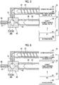
- Fig. 1 is a view showing an injection unit according to a first embodiment, and shows a first state of a valve body of a direction changeover valve.
- Fig. 2 is a view showing the injection unit according to the first embodiment, and shows a second state of the valve body of the direction changeover valve.
- Figs. 1 and 2 are sectional views perpendicular to a rotation center line of the valve body.
- an injection unit 10 includes a screw cylinder 20, a screw 22, a screw drive section 24, a plunger cylinder 30, a plunger 32, a plunger drive section 34, a nozzle 40, a direction changeover valve 50, and a controller 80.
- a solid molding material is supplied from the outside of the screw cylinder 20 to the inside thereof.
- the screw cylinder 20 heats and melts the solid molding material.
- a heating source such as a heater is provided on the outer periphery of the screw cylinder 20.
- the screw cylinder 20 corresponds to a first cylinder described in claims.
- the screw 22 is disposed inside the screw cylinder 20, and moves the molding material inside the screw cylinder 20.
- the screw 22 may be disposed to freely move forward and backward and to be rotatable inside the screw cylinder 20.
- the screw 22 may be disposed so as not to freely move forward and backward and so as to be rotatable inside the screw cylinder 20.
- the screw drive section 24 operates the screw 22.
- the screw drive section 24 includes a screw rotation motor 25 and a screw forward-backward movement motor 26.
- the screw rotation motor 25 rotates the screw 22.
- the screw forward-backward movement motor 26 moves the screw 22 forward and backward.
- a movement conversion mechanism which converts rotation motion of the screw forward-backward movement motor 26 into linear motion of the screw 22 is provided between the screw 22 and the screw forward-backward movement motor 26.
- the movement conversion mechanism is configured of a ball screw or the like.
- a molding material is supplied from the screw cylinder 20 to the inside of the plunger cylinder 30.
- a heating source such as a heater is provided on the outer periphery of the plunger cylinder 30.
- the plunger cylinder 30 corresponds to a second cylinder described in claims.
- the plunger 32 is disposed inside the plunger cylinder 30, and moves the molding material inside the plunger cylinder 30.
- the plunger 32 is disposed to freely move forward and backward inside the plunger cylinder 30.
- the plunger drive section 34 operates the plunger 32.
- the plunger drive section 34 includes a plunger forward-backward movement motor 36.
- the plunger forward-backward movement motor 36 moves the plunger 32 forward and backward.
- a movement conversion mechanism which converts rotation motion of the plunger forward-backward movement motor 36 into linear motion of the plunger 32 is provided between the plunger 32 and the plunger forward-backward movement motor 36.
- the movement conversion mechanism is configured of a ball screw or the like.
- the nozzle 40 injects a molding material which is supplied from the direction changeover valve 50 to a mold unit.
- a liquid molding material which fills the inside of the mold unit is solidified, and a molding product is molded.
- the direction changeover valve 50 switches a flow direction of the molding material between the screw cylinder 20, the plunger cylinder 30, and the nozzle 40.
- the direction changeover valve 50 includes a valve casing 60 and a valve body 70.
- the valve casing 60 includes a screw cylinder connection port 61, a plunger cylinder connection port 62, and a nozzle connection port 63.
- the screw cylinder connection port 61 communicates with the inside of the screw cylinder 20.
- the screw cylinder connection port 61 corresponds to a first cylinder connection port described in claims.
- the plunger cylinder connection port 62 communicates with the inside of the plunger cylinder30.
- the plunger cylinder connection port 62 corresponds to a second cylinder connection port described in claims.
- the nozzle connection port 63 communicates with the inside of the nozzle 40.
- the plunger cylinder connection port 62 and the nozzle connection port 63 are provided on sides opposite to each other in a state where the rotation center line of the valve body 70 is interposed therebetween.
- the screw cylinder connection port 61 is provided at a position of approximately the same distance along the outer periphery of the valve body 70 from both the plunger cylinder connection port 62 and the nozzle connection port 63. That is, the plunger cylinder connection port 62, the screw cylinder connection port 61, and the nozzle connection port 63 are disposed at a pitch of 90° in this order in a predetermined direction (counterclockwise direction in Figs. 1 and 2 ) with the rotation center line of the valve body 70 as a center.
- the valve body 70 rotates inside the valve casing 60, and is switched to a first state (refer to Fig. 1 ) and a second state (refer to Fig. 2 ).
- a first state (refer to Fig. 1 ) and a second state (refer to Fig. 2 ).
- the valve body 70 is in the first state, the screw cylinder connection port 61 and the plunger cylinder connection port 62 communicate with each other, and the nozzle connection port 63 is blocked.
- the valve body 70 is in the second state, the plunger cylinder connection port 62 and the nozzle connection port 63 communicate with each other, and the screw cylinder connection port 61 is blocked.
- the state of the valve body 70 is not limited to the first state shown in Fig. 1 and the second state shown in Fig. 2 .
- the valve body 70 may be in a state where the screw cylinder connection port 61, the plunger cylinder connection port 62, and the nozzle connection port 63 are simultaneously blocked.
- the valve body 70 may be in a state where the screw cylinder connection port 61 and the nozzle connection port 63 communicate with each other and the plunger cylinder connection port 62 is blocked.
- the controller 80 includes a Center Processing Unit (CPU) 81 and a recording medium 82 such as a memory.
- the controller 80 executes a program stored in the recording medium 82 by the CPU 81, and controls the screw drive section 24, the plunger drive section 34, the direction changeover valve 50, or the like.
- the controller 80 drives the screw rotation motor 25, rotates the screw 22 at a setting rotating speed, and feeds a molding material forward along spiral grooves of the screw 22. Accordingly, the molding material is gradually melted. A liquid molding material is fed to the front of the screw 22 and is accumulated in front of the screw cylinder 20, and the screw 22 is moved backward.
- the controller 80 may drive the screw forward-backward movement motor 26 to apply a setting backpressure to the screw 22. If the screw 22 moves backward to a predetermined position and a molding material having a predetermined amount is accumulated in front of the screw 22, the controller 80 stops the drive of the screw rotation motor 25.
- the controller 80 drives the screw forward-backward movement motor 26 to move the screw 22 forward. Accordingly, the molding material flows from the screw cylinder 20 into the plunger cylinder 30 via the valve body 70 in the first state. As a result, the molding material is accumulated in front of the plunger 32, and the plunger 32 is moved backward.
- the controller 80 may drive the plunger forward-backward movement motor 36 to apply a setting backpressure to the plunger 32. If the plunger 32 moves backward to a predetermined position and a molding material having a predetermined amount is accumulated in front of the plunger 32, the controller 80 stops the drive of the screw forward-backward movement motor 26 and stops the drive of the plunger forward-backward movement motor 36.
- the controller 80 of the present embodiment may move the screw 22 forward and backward but may not move the screw 22 forward and backward.
- the screw 22 does not move forward and backward and the screw 22 rotates. Accordingly, the molding material is fed forward along the spiral grooves of the screw 22, and the molding material flows from the screw cylinder 20 into the plunger cylinder 30.
- the controller 80 controls a filling process.
- the controller 80 rotates the valve body 70 of the direction changeover valve 50 between the plasticizing process and the filling process, and switches the state of the valve body 70 from the first state shown in Fig. 1 to the second state shown in Fig. 2 .
- the controller 80 drives the plunger forward-backward movement motor 36 and moves the plunger 32 forward. Accordingly, the molding material flows from the plunger cylinder 30 into the nozzle 40 via the valve body 70 in the second state, and the inside of the mold unit is filled with the liquid molding material from the nozzle 40. The filled molding material is solidified, and the molding product is molded.
- the controller 80 rotates the valve body 70 of the direction changeover valve 50 and returns the state of the valve body 70 from the second state shown in Fig. 2 to the first state shown in Fig. 1 .
- the rotation direction of the valve body 70 when the state of the valve body 70 is switched from the second state shown in Fig. 2 to the first state shown in Fig. 1 is opposite to the rotation direction of the valve body 70 when the state of the valve body 70 is switched from the first state shown in Fig. 1 to the second state shown in Fig. 2 .
- the controller 80 repeatedly performs the plasticizing processes, the filling processes, or the like, and repeatedly manufactures the molding products.
- the valve body 70 of the present embodiment includes a first plug portion 71 and a second plug portion 72 with a gap therebetween along the outer periphery of the valve body 70.
- the first plug portion 71 blocks the nozzle connection port 63 when the state of the valve body 70 becomes the first state shown in Fig. 1 .
- the second plug portion 72 blocks the screw cylinder connection port 61 when the state of the valve body 70 becomes the second state shown in Fig. 2 .
- the first plug portion 71 and the second plug portion 72 are connected to each other and integrally rotate with each other.
- the valve body 70 includes a flow path through which the molding material flows between the first plug portion 71 and the second plug portion 72.
- the valve body 70 includes a first flow path 73 and a second flow path 74 between the first plug portion 71 and the second plug portion 72.
- the first flow path 73 is used in the plasticizing process and communicates with the screw cylinder connection port 61 and the plunger cylinder connection port 62.
- the first flow path 73 is formed in a polygonal line shape in a sectional view.
- the second flow path 74 is used in the filling process and communicates with the plunger cylinder connection port 62 and the nozzle connection port 63.
- the second flow path 74 is formed in linear shape in a sectional view.
- the first flow path 73 and the second flow path 74 intersect each other midway in Figs. 1 and 2 , and are formed in an approximately K shape in a sectional view. In addition, the first flow path 73 and the second flow path 74 may not intersect each other midway.
- An inlet 73a of the first flow path 73 and an outlet 74b of the second flow path 74 are provided on one side of the first plug portion 71.
- the inlet 73a of the first flow path 73 and the outlet 74b of the second flow path 74 are partitioned by a first partition portion 75.
- the inlet 73a and the outlet 74b may not be partitioned and may be collectively formed in one portion.
- an outlet 73b of the first flow path 73 and an inlet 74a of the second flow path 74 are provided on the side opposite to the first plug portion 71.
- the outlet 73b of the first flow path 73 and the inlet 74a of the second flow path 74 are partitioned by a second partition portion 76.
- the outlet 73b and the inlet 74a may not be partitioned and may be collectively formed in one portion.
- the first plug portion 71 and the second plug portion 72 are provided with a gap therebetween along the outer periphery of the valve body 70.
- the plug portion which blocks the nozzle connection port 63 when the state of the valve body 70 becomes the first state is the same as the plug portion which blocks the screw cylinder connection port 61 when the state of the valve body 70 becomes the second state.
- the rotation angle of the valve body 70 required for switching the state to the first state and the second state can be decreased than that of the related art.
- the rotation angle of the valve body 70 required for switching the state to the first state and the second state can be decreased from 90° of the related art to 45° by half. Accordingly, time required for switching the flow direction of the molding material can be shortened, and molding cycle time can be shortened.
- the length of the cylinder can be decreased, and a volume of a tank which stores an operating liquid of the cylinder can be decreased.
- the rotation angle of the valve body 70 required for switching the state to the first state and the second state is not limited to 45°, and may be 45° or more or may be less than 45°.
- the rotation angle of the valve body 70 is not limited as long as the rotation angle of the valve body 70 required for switching the state to the first state and the second state can be decreased.
- the rotation angle of the valve body 70A required for switching the state to the first state and the second state is less than 45°.
- valve body 70 of the present embodiment includes the first partition portion 75 between the first plug portion 71 and the second plug portion 72, and the first partition portion 75 partitions the inlet 73a of the first flow path 73 and the outlet 74b of the second flow path 74. Accordingly, it is possible to decrease stagnation of the flow of the molding material.
- valve body 70 of the present embodiment includes the second partition portion 76 between the first plug portion 71 and the secondplugportion 72, and the second partition portion 76 partitions the outlet 73b of the first flow path 73 and the inlet 74a of the second flow path 74. Accordingly, it is possible to decrease stagnation of the flow of the molding material.
- the screw cylinder 20 of the embodiment is parallel to the plunger cylinder 30.
- the screw cylinder 20 may be perpendicular to the plunger cylinder 30 or may be inclined to the plunger cylinder 30.
- the plunger cylinder connection port 62, the screw cylinder connection port 61, and the nozzle connection port 63 are disposed at a pitch of 90° in this order around the rotation center line of the valve body 70.
- the present invention is not limited to this deposition.
- the screw cylinder connection port 61 may be disposed to be close to one of the plunger cylinder connection port 62 and the nozzle connection port 63 and to be away from the other thereof.
- the screw cylinder 20 to which a solid molding material is supplied from the outside is used as the first cylinder.
- the plunger cylinder to which a liquid molding material is supplied from the outside may be used as the first cylinder.
- the plunger may be disposed inside the first cylinder to freely move forward and backward.
- the direction changeover valve 50 of the above-described embodiment is used in the injection unit 10.
- the direction changeover valve 50 may be used in other devices (for example, a device which moves the injection unit or the like) included in an injection molding machine, or devices other than the injection molding machine.
- the screw cylinder 20, the plunger cylinder 30, and the nozzle 40 correspond to a first member, a second member, and a third member disclosed in claims.
- the molding material corresponds to a fluid disclosed in claims. The fluid is not limited to the molding material.
Landscapes
- Engineering & Computer Science (AREA)
- Manufacturing & Machinery (AREA)
- Mechanical Engineering (AREA)
- Injection Moulding Of Plastics Or The Like (AREA)
Abstract
Description
- Certain embodiment of the present invention relates to an injection unit and a direction changeover valve.
- Priority is claimed to Japanese Patent Application No.
2015-229728, filed November 25, 2015 - A pre-plasticizing injection molding portion disclosed in Japanese Unexamined Patent Application Publication No.
7-117087 - In the related art, switching of a flow direction of a molding material takes time, causing a molding cycle time to increase.
- The present invention is made in consideration of the above-described circumstances, and a main object thereof is to provide an injection unit in which a time required for switching a flow direction of a molding material can be shortened.
- In order to achieve the above-described object, according to an aspect of the present invention, there is provided an injection unit, including: a first cylinder; a second cylinder; a nozzle; and a direction changeover valve which switches a flow direction of a molding material between the first cylinder, the second cylinder, and the nozzle, in which the direction changeover valve includes a valve casing and a valve body which is rotatable inside the valve casing, the valve casing includes a first cylinder connection port which communicates with the inside of the first cylinder, a second cylinder connection port which communicates with the inside of the second cylinder, and a nozzle connection port which communicates with the inside of the nozzle, and the valve body includes a first plug portion which blocks the nozzle connection port and communicates the first cylinder connection port and the second cylinder connection port with each other and a second plug portion which blocks the first cylinder connection port and communicates the second cylinder connection port and the nozzle connection port with each other, the first plug portion and the second plug portion have a gap therebetween along an outer periphery of the valve body.
- According to the aspect of the present invention, an injection unit in which the time required for switching a flow direction of a molding material can be shortened is provided.
-
-
Fig. 1 is a view showing an injection unit according to an embodiment, and shows a first state of a valve body of a direction changeover valve. -
Fig. 2 is a view showing the injection unit according to the embodiment, and shows a second state of the valve body of the direction changeover valve. -
Fig. 3 is a view showing an injection unit according to a first modification example, and shows a first state of a valve body of a direction changeover valve. -
Fig. 4 is a view showing the injection unit according to the first modification example, and shows a second state of the valve body of the direction changeover valve. -
Fig. 5 is a view showing an injection unit according to a second modification example, and shows a first state of a valve body of a direction changeover valve. -
Fig. 6 is a view showing the injection unit according to the second modification example, and shows a second state of the valve body of the direction changeover valve. - Hereinafter, an embodiment of the present invention is described with reference to the drawings. Meanwhile, in each drawing, the same or corresponding reference numerals are assigned to the same or corresponding configurations, and descriptions thereof are omitted.
-
Fig. 1 is a view showing an injection unit according to a first embodiment, and shows a first state of a valve body of a direction changeover valve.Fig. 2 is a view showing the injection unit according to the first embodiment, and shows a second state of the valve body of the direction changeover valve.Figs. 1 and 2 are sectional views perpendicular to a rotation center line of the valve body. As shown inFigs. 1 and 2 , aninjection unit 10 includes ascrew cylinder 20, ascrew 22, ascrew drive section 24, aplunger cylinder 30, aplunger 32, aplunger drive section 34, anozzle 40, adirection changeover valve 50, and acontroller 80. - A solid molding material is supplied from the outside of the
screw cylinder 20 to the inside thereof. Thescrew cylinder 20 heats and melts the solid molding material. A heating source such as a heater is provided on the outer periphery of thescrew cylinder 20. Thescrew cylinder 20 corresponds to a first cylinder described in claims. - The
screw 22 is disposed inside thescrew cylinder 20, and moves the molding material inside thescrew cylinder 20. Thescrew 22 may be disposed to freely move forward and backward and to be rotatable inside thescrew cylinder 20. In addition, thescrew 22 may be disposed so as not to freely move forward and backward and so as to be rotatable inside thescrew cylinder 20. - The
screw drive section 24 operates thescrew 22. For example, thescrew drive section 24 includes ascrew rotation motor 25 and a screw forward-backward movement motor 26. Thescrew rotation motor 25 rotates thescrew 22. The screw forward-backwardmovement motor 26 moves thescrew 22 forward and backward. A movement conversion mechanism which converts rotation motion of the screw forward-backward movement motor 26 into linear motion of thescrew 22 is provided between thescrew 22 and the screw forward-backward movement motor 26. For example, the movement conversion mechanism is configured of a ball screw or the like. - A molding material is supplied from the
screw cylinder 20 to the inside of theplunger cylinder 30. A heating source such as a heater is provided on the outer periphery of theplunger cylinder 30. Theplunger cylinder 30 corresponds to a second cylinder described in claims. - The
plunger 32 is disposed inside theplunger cylinder 30, and moves the molding material inside theplunger cylinder 30. Theplunger 32 is disposed to freely move forward and backward inside theplunger cylinder 30. - The
plunger drive section 34 operates theplunger 32. For example, theplunger drive section 34 includes a plunger forward-backward movement motor 36. The plunger forward-backwardmovement motor 36 moves theplunger 32 forward and backward. A movement conversion mechanism which converts rotation motion of the plunger forward-backward movement motor 36 into linear motion of theplunger 32 is provided between theplunger 32 and the plunger forward-backward movement motor 36. For example, the movement conversion mechanism is configured of a ball screw or the like. - The
nozzle 40 injects a molding material which is supplied from thedirection changeover valve 50 to a mold unit. A liquid molding material which fills the inside of the mold unit is solidified, and a molding product is molded. - The
direction changeover valve 50 switches a flow direction of the molding material between thescrew cylinder 20, theplunger cylinder 30, and thenozzle 40. Thedirection changeover valve 50 includes avalve casing 60 and avalve body 70. - The
valve casing 60 includes a screwcylinder connection port 61, a plungercylinder connection port 62, and anozzle connection port 63. The screwcylinder connection port 61 communicates with the inside of thescrew cylinder 20. The screwcylinder connection port 61 corresponds to a first cylinder connection port described in claims. The plungercylinder connection port 62 communicates with the inside of the plunger cylinder30. The plungercylinder connection port 62 corresponds to a second cylinder connection port described in claims. Thenozzle connection port 63 communicates with the inside of thenozzle 40. - For example, the plunger
cylinder connection port 62 and thenozzle connection port 63 are provided on sides opposite to each other in a state where the rotation center line of thevalve body 70 is interposed therebetween. Meanwhile, for example, the screwcylinder connection port 61 is provided at a position of approximately the same distance along the outer periphery of thevalve body 70 from both the plungercylinder connection port 62 and thenozzle connection port 63. That is, the plungercylinder connection port 62, the screwcylinder connection port 61, and thenozzle connection port 63 are disposed at a pitch of 90° in this order in a predetermined direction (counterclockwise direction inFigs. 1 and 2 ) with the rotation center line of thevalve body 70 as a center. - The
valve body 70 rotates inside thevalve casing 60, and is switched to a first state (refer toFig. 1 ) and a second state (refer toFig. 2 ). When thevalve body 70 is in the first state, the screwcylinder connection port 61 and the plungercylinder connection port 62 communicate with each other, and thenozzle connection port 63 is blocked. Meanwhile, thevalve body 70 is in the second state, the plungercylinder connection port 62 and thenozzle connection port 63 communicate with each other, and the screwcylinder connection port 61 is blocked. - In addition, the state of the
valve body 70 is not limited to the first state shown inFig. 1 and the second state shown inFig. 2 . For example, thevalve body 70 may be in a state where the screwcylinder connection port 61, the plungercylinder connection port 62, and thenozzle connection port 63 are simultaneously blocked. In addition, thevalve body 70 may be in a state where the screwcylinder connection port 61 and thenozzle connection port 63 communicate with each other and the plungercylinder connection port 62 is blocked. - The
controller 80 includes a Center Processing Unit (CPU) 81 and arecording medium 82 such as a memory. Thecontroller 80 executes a program stored in therecording medium 82 by theCPU 81, and controls thescrew drive section 24, theplunger drive section 34, thedirection changeover valve 50, or the like. - For example, in a plasticizing process, the
controller 80 drives thescrew rotation motor 25, rotates thescrew 22 at a setting rotating speed, and feeds a molding material forward along spiral grooves of thescrew 22. Accordingly, the molding material is gradually melted. A liquid molding material is fed to the front of thescrew 22 and is accumulated in front of thescrew cylinder 20, and thescrew 22 is moved backward. - In the plasticizing process, in order to prevent a sudden backward movement of the
screw 22, thecontroller 80 may drive the screw forward-backward movement motor 26 to apply a setting backpressure to thescrew 22. If thescrew 22 moves backward to a predetermined position and a molding material having a predetermined amount is accumulated in front of thescrew 22, thecontroller 80 stops the drive of thescrew rotation motor 25. - In the plasticizing process, after the molding material having a predetermined amount is accumulated in front of the
screw 22, thecontroller 80 drives the screw forward-backward movement motor 26 to move thescrew 22 forward. Accordingly, the molding material flows from thescrew cylinder 20 into theplunger cylinder 30 via thevalve body 70 in the first state. As a result, the molding material is accumulated in front of theplunger 32, and theplunger 32 is moved backward. - In the plasticizing process, in order to prevent a sudden backward movement of the
plunger 32, thecontroller 80 may drive the plunger forward-backward movement motor 36 to apply a setting backpressure to theplunger 32. If theplunger 32 moves backward to a predetermined position and a molding material having a predetermined amount is accumulated in front of theplunger 32, thecontroller 80 stops the drive of the screw forward-backward movement motor 26 and stops the drive of the plunger forward-backward movement motor 36. - In addition, the plasticizing process, the
controller 80 of the present embodiment may move thescrew 22 forward and backward but may not move thescrew 22 forward and backward. Thescrew 22 does not move forward and backward and thescrew 22 rotates. Accordingly, the molding material is fed forward along the spiral grooves of thescrew 22, and the molding material flows from thescrew cylinder 20 into theplunger cylinder 30. - After the molding material having a predetermined is accumulated in front of the
plunger 32, thecontroller 80 controls a filling process. Thecontroller 80 rotates thevalve body 70 of thedirection changeover valve 50 between the plasticizing process and the filling process, and switches the state of thevalve body 70 from the first state shown inFig. 1 to the second state shown inFig. 2 . - In the filling process, the
controller 80 drives the plunger forward-backward movement motor 36 and moves theplunger 32 forward. Accordingly, the molding material flows from theplunger cylinder 30 into thenozzle 40 via thevalve body 70 in the second state, and the inside of the mold unit is filled with the liquid molding material from thenozzle 40. The filled molding material is solidified, and the molding product is molded. - After the filling process is completed, before the
controller 80 supplies the molding material from thescrew cylinder 20 to theplunger cylinder 30 in the next plasticizing process, thecontroller 80 rotates thevalve body 70 of thedirection changeover valve 50 and returns the state of thevalve body 70 from the second state shown inFig. 2 to the first state shown inFig. 1 . The rotation direction of thevalve body 70 when the state of thevalve body 70 is switched from the second state shown inFig. 2 to the first state shown inFig. 1 is opposite to the rotation direction of thevalve body 70 when the state of thevalve body 70 is switched from the first state shown inFig. 1 to the second state shown inFig. 2 . - The
controller 80 repeatedly performs the plasticizing processes, the filling processes, or the like, and repeatedly manufactures the molding products. - As shown in
Figs. 1 and 2 , thevalve body 70 of the present embodiment includes afirst plug portion 71 and asecond plug portion 72 with a gap therebetween along the outer periphery of thevalve body 70. Thefirst plug portion 71 blocks thenozzle connection port 63 when the state of thevalve body 70 becomes the first state shown inFig. 1 . Meanwhile, thesecond plug portion 72 blocks the screwcylinder connection port 61 when the state of thevalve body 70 becomes the second state shown inFig. 2 . Thefirst plug portion 71 and thesecond plug portion 72 are connected to each other and integrally rotate with each other. - The
valve body 70 includes a flow path through which the molding material flows between thefirst plug portion 71 and thesecond plug portion 72. For example, thevalve body 70 includes afirst flow path 73 and asecond flow path 74 between thefirst plug portion 71 and thesecond plug portion 72. - The
first flow path 73 is used in the plasticizing process and communicates with the screwcylinder connection port 61 and the plungercylinder connection port 62. For example, as shown inFigs. 1 and 2 , thefirst flow path 73 is formed in a polygonal line shape in a sectional view. - Meanwhile, the
second flow path 74 is used in the filling process and communicates with the plungercylinder connection port 62 and thenozzle connection port 63. For example, as shown inFigs. 1 and 2 , thesecond flow path 74 is formed in linear shape in a sectional view. - The
first flow path 73 and thesecond flow path 74 intersect each other midway inFigs. 1 and 2 , and are formed in an approximately K shape in a sectional view. In addition, thefirst flow path 73 and thesecond flow path 74 may not intersect each other midway. - An
inlet 73a of thefirst flow path 73 and anoutlet 74b of thesecond flow path 74 are provided on one side of thefirst plug portion 71. In the present embodiment, theinlet 73a of thefirst flow path 73 and theoutlet 74b of thesecond flow path 74 are partitioned by afirst partition portion 75. However, as shown inFigs. 3 and 4 , theinlet 73a and theoutlet 74b may not be partitioned and may be collectively formed in one portion. - Meanwhile, an
outlet 73b of thefirst flow path 73 and aninlet 74a of thesecond flow path 74 are provided on the side opposite to thefirst plug portion 71. In the present embodiment, theoutlet 73b of thefirst flow path 73 and theinlet 74a of thesecond flow path 74 are partitioned by asecond partition portion 76. However, as shown inFigs. 3 and 4 , theoutlet 73b and theinlet 74a may not be partitioned and may be collectively formed in one portion. - As described above, in the present embodiment, the
first plug portion 71 and thesecond plug portion 72 are provided with a gap therebetween along the outer periphery of thevalve body 70. Meanwhile, in Patent Document 1, the plug portion which blocks thenozzle connection port 63 when the state of thevalve body 70 becomes the first state is the same as the plug portion which blocks the screwcylinder connection port 61 when the state of thevalve body 70 becomes the second state. According to the present embodiment, since thefirst plug portion 71 and thesecond plug portion 72 are separately provided along the outer periphery of thevalve body 70, the rotation angle of thevalve body 70 required for switching the state to the first state and the second state can be decreased than that of the related art. Specifically, the rotation angle of thevalve body 70 required for switching the state to the first state and the second state can be decreased from 90° of the related art to 45° by half. Accordingly, time required for switching the flow direction of the molding material can be shortened, and molding cycle time can be shortened. In addition, in a case where a cylinder is used as a drive source which rotates thevalve body 70, the length of the cylinder can be decreased, and a volume of a tank which stores an operating liquid of the cylinder can be decreased. - In addition, the rotation angle of the
valve body 70 required for switching the state to the first state and the second state is not limited to 45°, and may be 45° or more or may be less than 45°. The rotation angle of thevalve body 70 is not limited as long as the rotation angle of thevalve body 70 required for switching the state to the first state and the second state can be decreased. For example, in a case where a first plug portion 71A and a second plug portion 72A shown inFigs. 5 and 6 are used, the rotation angle of thevalve body 70A required for switching the state to the first state and the second state is less than 45°. - In addition, the
valve body 70 of the present embodiment includes thefirst partition portion 75 between thefirst plug portion 71 and thesecond plug portion 72, and thefirst partition portion 75 partitions theinlet 73a of thefirst flow path 73 and theoutlet 74b of thesecond flow path 74. Accordingly, it is possible to decrease stagnation of the flow of the molding material. - Moreover, the
valve body 70 of the present embodiment includes thesecond partition portion 76 between thefirst plug portion 71 and thesecondplugportion 72, and thesecond partition portion 76 partitions theoutlet 73b of thefirst flow path 73 and theinlet 74a of thesecond flow path 74. Accordingly, it is possible to decrease stagnation of the flow of the molding material. - Hereinbefore, the embodiment of the injection unit is described. However, the present invention is not limited to the above-described embodiment. Various modifications and improvement may be applied to the present invention within the scope which does not depart from the gist of the present invention described in claims.
- The
screw cylinder 20 of the embodiment is parallel to theplunger cylinder 30. However, thescrew cylinder 20 may be perpendicular to theplunger cylinder 30 or may be inclined to theplunger cylinder 30. - In the above-described embodiment, the plunger
cylinder connection port 62, the screwcylinder connection port 61, and thenozzle connection port 63 are disposed at a pitch of 90° in this order around the rotation center line of thevalve body 70. However, the present invention is not limited to this deposition. For example, the screwcylinder connection port 61 may be disposed to be close to one of the plungercylinder connection port 62 and thenozzle connection port 63 and to be away from the other thereof. - In the above-described embodiment, the
screw cylinder 20 to which a solid molding material is supplied from the outside is used as the first cylinder. However, the plunger cylinder to which a liquid molding material is supplied from the outside may be used as the first cylinder. The plunger may be disposed inside the first cylinder to freely move forward and backward. - The
direction changeover valve 50 of the above-described embodiment is used in theinjection unit 10. However, thedirection changeover valve 50 may be used in other devices (for example, a device which moves the injection unit or the like) included in an injection molding machine, or devices other than
the injection molding machine. In the above-described embodiment, thescrew cylinder 20, theplunger cylinder 30, and thenozzle 40 correspond to a first member, a second member, and a third member disclosed in claims. In addition, in the above-described embodiment, the molding material corresponds to a fluid disclosed in claims. The fluid is not limited to the
molding material.
Claims (6)
- An injection unit, comprising:a first cylinder;a second cylinder;a nozzle; anda direction changeover valve which switches a flow direction of a molding material between the first cylinder, the second cylinder, and the nozzle,the direction changeover valve includes a valve casing and a valve body which is rotatable inside the valve casing,the valve casing includes a first cylinder connection port which communicates with the inside of the first cylinder, a second cylinder connection port which communicates with the inside of the second cylinder, and a nozzle connection port which communicates with the inside of the nozzle, andthe valve body includes a first plug portion which blocks the nozzle connection port and communicates the first cylinder connection port and the second cylinder connection port with each other and a second plug portion which blocks the first cylinder connection port and communicates the second cylinder connection port and the nozzle connection port with each other, the first plug portion and the second plug portion have a gap therebetween along an outer periphery of the valve body.
- The injection unit according to claim 1,wherein the valve body includes a flow path through which the molding material flows between the first plug portion and the second plug portion.
- The injection unit according to claim 1 or 2,wherein the valve body includes a first flow path which communicates with the first cylinder connection port and the second cylinder connection port, and a second flow path which communicates with the second cylinder connection port and the nozzle connection port between the first plug portion and the second plug portion.
- The injection unit according to claim 3,wherein the valve body includes a partition portion which partitions an inlet of the first flow path and an outlet of the second flow path between the first plug portion and the second plug portion.
- The injection unit according to claim 3 or 4,wherein the valve body includes a partition portion which partitions an outlet of the first flow path and an inlet of the second flow path between the first plug portion and the second plug portion.
- A direction changeover valve which switches a flow direction of a fluid between a first member, a second member, and a third member, comprising:a valve casing; anda valve body which is rotatable inside the valve casing,the valve casing includes a first member connection port which communicates with the inside of the first member, a second member connection port which communicates with the inside of the second member, and a third member connection port which communicates with the inside of the third member, andthe valve body includes a first plug portion which blocks the third member connection port and communicates the first member connection port and the second member connection port with each other and a second plug portion which blocks the first member connection port and communicates the second member connection port and the third member connection port with each other, the first plug portion and the second plug portion have a gap therebetween along an outer periphery of the valve body.
Applications Claiming Priority (1)
| Application Number | Priority Date | Filing Date | Title |
|---|---|---|---|
| JP2015229728A JP6522486B2 (en) | 2015-11-25 | 2015-11-25 | Injection device and direction switching valve |
Publications (2)
| Publication Number | Publication Date |
|---|---|
| EP3173207A1 true EP3173207A1 (en) | 2017-05-31 |
| EP3173207B1 EP3173207B1 (en) | 2019-03-13 |
Family
ID=57288215
Family Applications (1)
| Application Number | Title | Priority Date | Filing Date |
|---|---|---|---|
| EP16198332.5A Not-in-force EP3173207B1 (en) | 2015-11-25 | 2016-11-11 | Injection unit with direction changeover valve |
Country Status (4)
| Country | Link |
|---|---|
| EP (1) | EP3173207B1 (en) |
| JP (1) | JP6522486B2 (en) |
| CN (1) | CN106945241A (en) |
| CA (1) | CA2949475C (en) |
Families Citing this family (3)
| Publication number | Priority date | Publication date | Assignee | Title |
|---|---|---|---|---|
| CN111923338B (en) * | 2020-09-17 | 2021-01-26 | 潍坊工程职业学院 | Circulating injection molding machine |
| JP7528287B2 (en) * | 2022-03-23 | 2024-08-05 | キヤノン株式会社 | Manufacturing apparatus and method for manufacturing molded products |
| CN117549487B (en) * | 2024-01-11 | 2024-04-12 | 成都鸿能精密机械有限公司 | Shuttle valve assembly |
Citations (4)
| Publication number | Priority date | Publication date | Assignee | Title |
|---|---|---|---|---|
| EP0254366A1 (en) * | 1986-07-21 | 1988-01-27 | Stamicarbon B.V. | Process and device for injection moulding an object consisting of a number of layers of different materials |
| JPH07117087A (en) | 1993-10-27 | 1995-05-09 | Komatsu Ltd | Injection compression molding equipment |
| JP2004243704A (en) * | 2003-02-17 | 2004-09-02 | Kata System:Kk | Preplasticization type injection molding machine |
| JP2008132627A (en) * | 2006-11-27 | 2008-06-12 | Matsushita Electric Works Ltd | Injection molding machine |
Family Cites Families (10)
| Publication number | Priority date | Publication date | Assignee | Title |
|---|---|---|---|---|
| GB270997A (en) * | 1927-01-03 | 1927-05-19 | John Christopher Stead | Improvements relating to multiple way cocks or valves |
| US3048192A (en) * | 1957-08-14 | 1962-08-07 | Cordis Corp | Surgical valve |
| JP3341523B2 (en) * | 1994-06-17 | 2002-11-05 | 株式会社デンソー | Flow control valve and hot water type heating device using the same |
| JP4455559B2 (en) * | 2006-09-11 | 2010-04-21 | 株式会社日本製鋼所 | Rotary valve for injection molding machine |
| CN101077611A (en) * | 2007-05-31 | 2007-11-28 | 华南理工大学 | Pulse type shock processing on-line compound injection molding method and its equipment |
| CN102575783B (en) * | 2009-07-20 | 2014-07-30 | 戴维·R·邓肯 | Multiport Stopcock Valves and Flow Designation Systems |
| CN103264492B (en) * | 2013-06-04 | 2015-08-19 | 浙江大学 | The injection device of the miniature injection machine of differential gearing and method |
| CN103753762B (en) * | 2014-01-24 | 2016-04-13 | 广东富瑞精密机械有限公司 | Hierarchical storage injection molding machine |
| CN104097308A (en) * | 2014-07-15 | 2014-10-15 | 宁波海洲机械有限公司 | Double-step injection device |
| CN204076712U (en) * | 2014-07-15 | 2015-01-07 | 宁波海洲机械有限公司 | Two-Stage Injection Device |
-
2015
- 2015-11-25 JP JP2015229728A patent/JP6522486B2/en active Active
-
2016
- 2016-11-11 EP EP16198332.5A patent/EP3173207B1/en not_active Not-in-force
- 2016-11-17 CN CN201611065482.4A patent/CN106945241A/en active Pending
- 2016-11-24 CA CA2949475A patent/CA2949475C/en active Active
Patent Citations (4)
| Publication number | Priority date | Publication date | Assignee | Title |
|---|---|---|---|---|
| EP0254366A1 (en) * | 1986-07-21 | 1988-01-27 | Stamicarbon B.V. | Process and device for injection moulding an object consisting of a number of layers of different materials |
| JPH07117087A (en) | 1993-10-27 | 1995-05-09 | Komatsu Ltd | Injection compression molding equipment |
| JP2004243704A (en) * | 2003-02-17 | 2004-09-02 | Kata System:Kk | Preplasticization type injection molding machine |
| JP2008132627A (en) * | 2006-11-27 | 2008-06-12 | Matsushita Electric Works Ltd | Injection molding machine |
Also Published As
| Publication number | Publication date |
|---|---|
| CA2949475C (en) | 2018-12-18 |
| CA2949475A1 (en) | 2017-05-25 |
| JP2017094618A (en) | 2017-06-01 |
| EP3173207B1 (en) | 2019-03-13 |
| JP6522486B2 (en) | 2019-05-29 |
| CN106945241A (en) | 2017-07-14 |
Similar Documents
| Publication | Publication Date | Title |
|---|---|---|
| JP6092075B2 (en) | Injection molding machine | |
| JP2012131115A (en) | Injection molding device | |
| CA2949475C (en) | Injection unit and direction changeover valve | |
| EP2907644B1 (en) | Injection unit and injection molding method | |
| JP7500328B2 (en) | Injection molding machine | |
| US20210016482A1 (en) | Plasticizing device, injection device, molding apparatus, and manufacturing method of molded parts | |
| EP3381643B1 (en) | Injection unit and direction switching valve | |
| EP2907645A1 (en) | Injection unit | |
| JP4390789B2 (en) | Integrated apparatus having a kneading part and an injection part | |
| CN102189635B (en) | Multi-axis injection molding apparatus | |
| CN108698295A (en) | Injection (mo(u)lding) machine | |
| US11602877B2 (en) | Method for manufacturing mold and mold | |
| CN116533515B (en) | Plasticizing equipment, 3D modeling equipment, and injection molding equipment | |
| JP6429923B2 (en) | Method of operating an injection device comprising a plasticizing device and a plunger type injection device | |
| KR101666404B1 (en) | Gas exhausting adapter nozzle for injection molding machine | |
| US11958222B2 (en) | Plasticizing device, injection molding machine, and three-dimensional shaping apparatus | |
| JP6177586B2 (en) | Injection molding machine | |
| JP2024141380A (en) | Material ejection device and three-dimensional modeling device | |
| JP2025064482A (en) | Injection Molding Machine | |
| JP2025180444A (en) | Plasticizing device and injection molding device | |
| JP6036283B2 (en) | Injection machine for injection molding machine | |
| JP5996521B2 (en) | Molding apparatus and manufacturing method | |
| JP2024035492A (en) | Injection molding machine and injection equipment | |
| JP2008132627A (en) | Injection molding machine | |
| JP2007001267A (en) | Injection molding device |
Legal Events
| Date | Code | Title | Description |
|---|---|---|---|
| PUAI | Public reference made under article 153(3) epc to a published international application that has entered the european phase |
Free format text: ORIGINAL CODE: 0009012 |
|
| STAA | Information on the status of an ep patent application or granted ep patent |
Free format text: STATUS: EXAMINATION IS IN PROGRESS |
|
| 17P | Request for examination filed |
Effective date: 20161111 |
|
| AK | Designated contracting states |
Kind code of ref document: A1 Designated state(s): AL AT BE BG CH CY CZ DE DK EE ES FI FR GB GR HR HU IE IS IT LI LT LU LV MC MK MT NL NO PL PT RO RS SE SI SK SM TR |
|
| AX | Request for extension of the european patent |
Extension state: BA ME |
|
| RIC1 | Information provided on ipc code assigned before grant |
Ipc: B29C 45/58 20060101ALI20180131BHEP Ipc: B29C 45/54 20060101AFI20180131BHEP |
|
| GRAP | Despatch of communication of intention to grant a patent |
Free format text: ORIGINAL CODE: EPIDOSNIGR1 |
|
| STAA | Information on the status of an ep patent application or granted ep patent |
Free format text: STATUS: GRANT OF PATENT IS INTENDED |
|
| INTG | Intention to grant announced |
Effective date: 20181001 |
|
| GRAS | Grant fee paid |
Free format text: ORIGINAL CODE: EPIDOSNIGR3 |
|
| GRAA | (expected) grant |
Free format text: ORIGINAL CODE: 0009210 |
|
| STAA | Information on the status of an ep patent application or granted ep patent |
Free format text: STATUS: THE PATENT HAS BEEN GRANTED |
|
| AK | Designated contracting states |
Kind code of ref document: B1 Designated state(s): AL AT BE BG CH CY CZ DE DK EE ES FI FR GB GR HR HU IE IS IT LI LT LU LV MC MK MT NL NO PL PT RO RS SE SI SK SM TR |
|
| REG | Reference to a national code |
Ref country code: GB Ref legal event code: FG4D |
|
| REG | Reference to a national code |
Ref country code: CH Ref legal event code: EP Ref country code: AT Ref legal event code: REF Ref document number: 1107101 Country of ref document: AT Kind code of ref document: T Effective date: 20190315 |
|
| REG | Reference to a national code |
Ref country code: IE Ref legal event code: FG4D |
|
| REG | Reference to a national code |
Ref country code: DE Ref legal event code: R096 Ref document number: 602016010974 Country of ref document: DE |
|
| REG | Reference to a national code |
Ref country code: CH Ref legal event code: NV Representative=s name: SCHNEIDER FELDMANN AG PATENT- UND MARKENANWAEL, CH |
|
| REG | Reference to a national code |
Ref country code: NL Ref legal event code: MP Effective date: 20190313 |
|
| REG | Reference to a national code |
Ref country code: LT Ref legal event code: MG4D |
|
| PG25 | Lapsed in a contracting state [announced via postgrant information from national office to epo] |
Ref country code: FI Free format text: LAPSE BECAUSE OF FAILURE TO SUBMIT A TRANSLATION OF THE DESCRIPTION OR TO PAY THE FEE WITHIN THE PRESCRIBED TIME-LIMIT Effective date: 20190313 Ref country code: NO Free format text: LAPSE BECAUSE OF FAILURE TO SUBMIT A TRANSLATION OF THE DESCRIPTION OR TO PAY THE FEE WITHIN THE PRESCRIBED TIME-LIMIT Effective date: 20190613 Ref country code: LT Free format text: LAPSE BECAUSE OF FAILURE TO SUBMIT A TRANSLATION OF THE DESCRIPTION OR TO PAY THE FEE WITHIN THE PRESCRIBED TIME-LIMIT Effective date: 20190313 Ref country code: SE Free format text: LAPSE BECAUSE OF FAILURE TO SUBMIT A TRANSLATION OF THE DESCRIPTION OR TO PAY THE FEE WITHIN THE PRESCRIBED TIME-LIMIT Effective date: 20190313 |
|
| PG25 | Lapsed in a contracting state [announced via postgrant information from national office to epo] |
Ref country code: LV Free format text: LAPSE BECAUSE OF FAILURE TO SUBMIT A TRANSLATION OF THE DESCRIPTION OR TO PAY THE FEE WITHIN THE PRESCRIBED TIME-LIMIT Effective date: 20190313 Ref country code: HR Free format text: LAPSE BECAUSE OF FAILURE TO SUBMIT A TRANSLATION OF THE DESCRIPTION OR TO PAY THE FEE WITHIN THE PRESCRIBED TIME-LIMIT Effective date: 20190313 Ref country code: RS Free format text: LAPSE BECAUSE OF FAILURE TO SUBMIT A TRANSLATION OF THE DESCRIPTION OR TO PAY THE FEE WITHIN THE PRESCRIBED TIME-LIMIT Effective date: 20190313 Ref country code: BG Free format text: LAPSE BECAUSE OF FAILURE TO SUBMIT A TRANSLATION OF THE DESCRIPTION OR TO PAY THE FEE WITHIN THE PRESCRIBED TIME-LIMIT Effective date: 20190613 Ref country code: GR Free format text: LAPSE BECAUSE OF FAILURE TO SUBMIT A TRANSLATION OF THE DESCRIPTION OR TO PAY THE FEE WITHIN THE PRESCRIBED TIME-LIMIT Effective date: 20190614 Ref country code: NL Free format text: LAPSE BECAUSE OF FAILURE TO SUBMIT A TRANSLATION OF THE DESCRIPTION OR TO PAY THE FEE WITHIN THE PRESCRIBED TIME-LIMIT Effective date: 20190313 |
|
| REG | Reference to a national code |
Ref country code: AT Ref legal event code: MK05 Ref document number: 1107101 Country of ref document: AT Kind code of ref document: T Effective date: 20190313 |
|
| PG25 | Lapsed in a contracting state [announced via postgrant information from national office to epo] |
Ref country code: ES Free format text: LAPSE BECAUSE OF FAILURE TO SUBMIT A TRANSLATION OF THE DESCRIPTION OR TO PAY THE FEE WITHIN THE PRESCRIBED TIME-LIMIT Effective date: 20190313 Ref country code: AL Free format text: LAPSE BECAUSE OF FAILURE TO SUBMIT A TRANSLATION OF THE DESCRIPTION OR TO PAY THE FEE WITHIN THE PRESCRIBED TIME-LIMIT Effective date: 20190313 Ref country code: PT Free format text: LAPSE BECAUSE OF FAILURE TO SUBMIT A TRANSLATION OF THE DESCRIPTION OR TO PAY THE FEE WITHIN THE PRESCRIBED TIME-LIMIT Effective date: 20190713 Ref country code: CZ Free format text: LAPSE BECAUSE OF FAILURE TO SUBMIT A TRANSLATION OF THE DESCRIPTION OR TO PAY THE FEE WITHIN THE PRESCRIBED TIME-LIMIT Effective date: 20190313 Ref country code: IT Free format text: LAPSE BECAUSE OF FAILURE TO SUBMIT A TRANSLATION OF THE DESCRIPTION OR TO PAY THE FEE WITHIN THE PRESCRIBED TIME-LIMIT Effective date: 20190313 Ref country code: RO Free format text: LAPSE BECAUSE OF FAILURE TO SUBMIT A TRANSLATION OF THE DESCRIPTION OR TO PAY THE FEE WITHIN THE PRESCRIBED TIME-LIMIT Effective date: 20190313 Ref country code: SK Free format text: LAPSE BECAUSE OF FAILURE TO SUBMIT A TRANSLATION OF THE DESCRIPTION OR TO PAY THE FEE WITHIN THE PRESCRIBED TIME-LIMIT Effective date: 20190313 Ref country code: EE Free format text: LAPSE BECAUSE OF FAILURE TO SUBMIT A TRANSLATION OF THE DESCRIPTION OR TO PAY THE FEE WITHIN THE PRESCRIBED TIME-LIMIT Effective date: 20190313 |
|
| PG25 | Lapsed in a contracting state [announced via postgrant information from national office to epo] |
Ref country code: SM Free format text: LAPSE BECAUSE OF FAILURE TO SUBMIT A TRANSLATION OF THE DESCRIPTION OR TO PAY THE FEE WITHIN THE PRESCRIBED TIME-LIMIT Effective date: 20190313 Ref country code: PL Free format text: LAPSE BECAUSE OF FAILURE TO SUBMIT A TRANSLATION OF THE DESCRIPTION OR TO PAY THE FEE WITHIN THE PRESCRIBED TIME-LIMIT Effective date: 20190313 |
|
| REG | Reference to a national code |
Ref country code: DE Ref legal event code: R097 Ref document number: 602016010974 Country of ref document: DE |
|
| PG25 | Lapsed in a contracting state [announced via postgrant information from national office to epo] |
Ref country code: IS Free format text: LAPSE BECAUSE OF FAILURE TO SUBMIT A TRANSLATION OF THE DESCRIPTION OR TO PAY THE FEE WITHIN THE PRESCRIBED TIME-LIMIT Effective date: 20190713 Ref country code: AT Free format text: LAPSE BECAUSE OF FAILURE TO SUBMIT A TRANSLATION OF THE DESCRIPTION OR TO PAY THE FEE WITHIN THE PRESCRIBED TIME-LIMIT Effective date: 20190313 |
|
| PLBE | No opposition filed within time limit |
Free format text: ORIGINAL CODE: 0009261 |
|
| STAA | Information on the status of an ep patent application or granted ep patent |
Free format text: STATUS: NO OPPOSITION FILED WITHIN TIME LIMIT |
|
| PG25 | Lapsed in a contracting state [announced via postgrant information from national office to epo] |
Ref country code: DK Free format text: LAPSE BECAUSE OF FAILURE TO SUBMIT A TRANSLATION OF THE DESCRIPTION OR TO PAY THE FEE WITHIN THE PRESCRIBED TIME-LIMIT Effective date: 20190313 |
|
| 26N | No opposition filed |
Effective date: 20191216 |
|
| PG25 | Lapsed in a contracting state [announced via postgrant information from national office to epo] |
Ref country code: SI Free format text: LAPSE BECAUSE OF FAILURE TO SUBMIT A TRANSLATION OF THE DESCRIPTION OR TO PAY THE FEE WITHIN THE PRESCRIBED TIME-LIMIT Effective date: 20190313 |
|
| PG25 | Lapsed in a contracting state [announced via postgrant information from national office to epo] |
Ref country code: TR Free format text: LAPSE BECAUSE OF FAILURE TO SUBMIT A TRANSLATION OF THE DESCRIPTION OR TO PAY THE FEE WITHIN THE PRESCRIBED TIME-LIMIT Effective date: 20190313 |
|
| REG | Reference to a national code |
Ref country code: DE Ref legal event code: R119 Ref document number: 602016010974 Country of ref document: DE |
|
| PG25 | Lapsed in a contracting state [announced via postgrant information from national office to epo] |
Ref country code: LU Free format text: LAPSE BECAUSE OF NON-PAYMENT OF DUE FEES Effective date: 20191111 Ref country code: MC Free format text: LAPSE BECAUSE OF FAILURE TO SUBMIT A TRANSLATION OF THE DESCRIPTION OR TO PAY THE FEE WITHIN THE PRESCRIBED TIME-LIMIT Effective date: 20190313 |
|
| REG | Reference to a national code |
Ref country code: BE Ref legal event code: MM Effective date: 20191130 |
|
| REG | Reference to a national code |
Ref country code: CH Ref legal event code: PFA Owner name: SUMITOMO HEAVY INDUSTRIES, LTD., JP Free format text: FORMER OWNER: SUMITOMO HEAVY INDUSTRIES, LTD., JP |
|
| PG25 | Lapsed in a contracting state [announced via postgrant information from national office to epo] |
Ref country code: DE Free format text: LAPSE BECAUSE OF NON-PAYMENT OF DUE FEES Effective date: 20200603 Ref country code: IE Free format text: LAPSE BECAUSE OF NON-PAYMENT OF DUE FEES Effective date: 20191111 Ref country code: FR Free format text: LAPSE BECAUSE OF NON-PAYMENT OF DUE FEES Effective date: 20191130 |
|
| PG25 | Lapsed in a contracting state [announced via postgrant information from national office to epo] |
Ref country code: BE Free format text: LAPSE BECAUSE OF NON-PAYMENT OF DUE FEES Effective date: 20191130 |
|
| PG25 | Lapsed in a contracting state [announced via postgrant information from national office to epo] |
Ref country code: CY Free format text: LAPSE BECAUSE OF FAILURE TO SUBMIT A TRANSLATION OF THE DESCRIPTION OR TO PAY THE FEE WITHIN THE PRESCRIBED TIME-LIMIT Effective date: 20190313 |
|
| GBPC | Gb: european patent ceased through non-payment of renewal fee |
Effective date: 20201111 |
|
| PG25 | Lapsed in a contracting state [announced via postgrant information from national office to epo] |
Ref country code: HU Free format text: LAPSE BECAUSE OF FAILURE TO SUBMIT A TRANSLATION OF THE DESCRIPTION OR TO PAY THE FEE WITHIN THE PRESCRIBED TIME-LIMIT; INVALID AB INITIO Effective date: 20161111 Ref country code: MT Free format text: LAPSE BECAUSE OF FAILURE TO SUBMIT A TRANSLATION OF THE DESCRIPTION OR TO PAY THE FEE WITHIN THE PRESCRIBED TIME-LIMIT Effective date: 20190313 |
|
| PG25 | Lapsed in a contracting state [announced via postgrant information from national office to epo] |
Ref country code: GB Free format text: LAPSE BECAUSE OF NON-PAYMENT OF DUE FEES Effective date: 20201111 |
|
| PGFP | Annual fee paid to national office [announced via postgrant information from national office to epo] |
Ref country code: CH Payment date: 20211014 Year of fee payment: 6 |
|
| PG25 | Lapsed in a contracting state [announced via postgrant information from national office to epo] |
Ref country code: MK Free format text: LAPSE BECAUSE OF FAILURE TO SUBMIT A TRANSLATION OF THE DESCRIPTION OR TO PAY THE FEE WITHIN THE PRESCRIBED TIME-LIMIT Effective date: 20190313 |
|
| REG | Reference to a national code |
Ref country code: CH Ref legal event code: PL |
|
| PG25 | Lapsed in a contracting state [announced via postgrant information from national office to epo] |
Ref country code: LI Free format text: LAPSE BECAUSE OF NON-PAYMENT OF DUE FEES Effective date: 20221130 Ref country code: CH Free format text: LAPSE BECAUSE OF NON-PAYMENT OF DUE FEES Effective date: 20221130 |