EP3171140A1 - Combination weighing device - Google Patents
Combination weighing device Download PDFInfo
- Publication number
- EP3171140A1 EP3171140A1 EP15821298.5A EP15821298A EP3171140A1 EP 3171140 A1 EP3171140 A1 EP 3171140A1 EP 15821298 A EP15821298 A EP 15821298A EP 3171140 A1 EP3171140 A1 EP 3171140A1
- Authority
- EP
- European Patent Office
- Prior art keywords
- distributing
- face
- conveying
- weighed object
- spacer member
- Prior art date
- Legal status (The legal status is an assumption and is not a legal conclusion. Google has not performed a legal analysis and makes no representation as to the accuracy of the status listed.)
- Granted
Links
Images




Classifications
-
- G—PHYSICS
- G01—MEASURING; TESTING
- G01G—WEIGHING
- G01G13/00—Weighing apparatus with automatic feed or discharge for weighing-out batches of material
- G01G13/02—Means for automatically loading weigh pans or other receptacles, e.g. disposable containers, under control of the weighing mechanism
- G01G13/022—Material feeding devices
- G01G13/026—Material feeding devices by mechanical conveying means, e.g. belt or vibratory conveyor
-
- G—PHYSICS
- G01—MEASURING; TESTING
- G01G—WEIGHING
- G01G19/00—Weighing apparatus or methods adapted for special purposes not provided for in the preceding groups
- G01G19/387—Weighing apparatus or methods adapted for special purposes not provided for in the preceding groups for combinatorial weighing, i.e. selecting a combination of articles whose total weight or number is closest to a desired value
-
- B—PERFORMING OPERATIONS; TRANSPORTING
- B01—PHYSICAL OR CHEMICAL PROCESSES OR APPARATUS IN GENERAL
- B01F—MIXING, e.g. DISSOLVING, EMULSIFYING OR DISPERSING
- B01F35/00—Accessories for mixers; Auxiliary operations or auxiliary devices; Parts or details of general application
- B01F35/80—Forming a predetermined ratio of the substances to be mixed
-
- B—PERFORMING OPERATIONS; TRANSPORTING
- B65—CONVEYING; PACKING; STORING; HANDLING THIN OR FILAMENTARY MATERIAL
- B65B—MACHINES, APPARATUS OR DEVICES FOR, OR METHODS OF, PACKAGING ARTICLES OR MATERIALS; UNPACKING
- B65B35/00—Supplying, feeding, arranging or orientating articles to be packaged
-
- B—PERFORMING OPERATIONS; TRANSPORTING
- B65—CONVEYING; PACKING; STORING; HANDLING THIN OR FILAMENTARY MATERIAL
- B65G—TRANSPORT OR STORAGE DEVICES, e.g. CONVEYORS FOR LOADING OR TIPPING, SHOP CONVEYOR SYSTEMS OR PNEUMATIC TUBE CONVEYORS
- B65G33/00—Screw or rotary spiral conveyors
- B65G33/24—Details
-
- G—PHYSICS
- G01—MEASURING; TESTING
- G01G—WEIGHING
- G01G13/00—Weighing apparatus with automatic feed or discharge for weighing-out batches of material
-
- G—PHYSICS
- G01—MEASURING; TESTING
- G01G—WEIGHING
- G01G13/00—Weighing apparatus with automatic feed or discharge for weighing-out batches of material
- G01G13/003—Details; specially adapted accessories
-
- G—PHYSICS
- G01—MEASURING; TESTING
- G01G—WEIGHING
- G01G19/00—Weighing apparatus or methods adapted for special purposes not provided for in the preceding groups
- G01G19/387—Weighing apparatus or methods adapted for special purposes not provided for in the preceding groups for combinatorial weighing, i.e. selecting a combination of articles whose total weight or number is closest to a desired value
- G01G19/393—Weighing apparatus or methods adapted for special purposes not provided for in the preceding groups for combinatorial weighing, i.e. selecting a combination of articles whose total weight or number is closest to a desired value using two or more weighing units
Definitions
- the present invention relates to a combination weighing apparatus.
- the patent literature 1 discloses a combination weighing apparatus.
- This combination weighing apparatus includes a distributing portion that rotates to convey a weighed object outward, a plurality of conveying portions arranged in a radial manner along a circumference of the distributing portion and convey the weighed object discharged from the distributing portion by a rotating screw, a plurality of hoppers that are provided corresponding to each conveying portion and receive the weighed object discharged from the conveying portion, and a plurality of weighing hoppers arranged below the plurality of hoppers.
- Patent Literature 1 Japanese Unexamined Patent Publication No. 2014-509290
- the weighed object When the distributing portion conveys a weighed object, the weighed object may enter an inside of the distributing portion.
- the weighed object In particular, in a case of weighed object having adhesiveness such as meat, when entering the inside of the distributing portion, the weighed object is not conveyed by the conveying portion and remains.
- maintainability is lowered due to necessity of an operation for removing the weighed object. For a combination weighing apparatus, therefore, it is required to prevent the weighed object from remaining.
- the present invention is intended to provide a combination weighing apparatus that can prevent a weighed object from remaining.
- the combination weighing apparatus includes a distributing portion that has a conveying face that conveys a weighed object and conveys the weighed object in a direction toward an outer edge portion of the conveying face and a plurality of conveying portions arranged in a radial manner along an outer edge portion of the distributing portion and convey the weighed object discharged from the distributing portion, in which the distributing portion is provided with a projecting portion lower than the conveying face in the outer edge portion of the conveying face.
- the distributing portion included in the combination weighing apparatus is provided with the projecting portion lower than the conveying face in the outer edge portion of the conveying face. This projecting portion makes it difficult for the weighed object to enter the inside of the distributing portion. As a result, the combination weighing apparatus can prevent the weighed object from remaining.
- the projecting portion may have a first extending portion that extends downwardly from the outer edge portion of the conveying face and a second extending portion that extends from a lower end portion of the first extending portion to the inside of the distributing portion. This makes it more difficult for the weighed object to enter the inside of the distributing portion.
- the projecting portion may have a connecting portion that connects the second extending portion with the inside face of the distributing portion. This ensures a rigidity of the projecting portion. As a result, damage or the like of the projecting portion can be prevented.
- a first spacer member arranged in a position opposite to a side face of an outside of the first extending portion may be provided. This allows the first spacer member to fill a gap if there is the gap generated between the projecting portion and a member arranged in a position opposite to the projecting portion. Therefore, the first spacer member can prevent the weighed object from entering the gap. Consequently, the combination weighing apparatus can prevent the weighed object from remaining.
- a second spacer member arranged in a position opposite to a bottom face of the second extending portion is provided and the bottom face of the second extending portion may contact a top face of the second spacer member.
- a third spacer member arranged in a position opposite to a side face of an inside of the connecting portion may be provided. This makes it more difficult for the weighed object to enter the inside of the distributing portion.
- the distributing portion may convey the weighed object by rotating.
- the weighed object is liable to be pulled into the inside by the rotation of the distributing portion and remains. Since the distributing portion includes the projecting portion, it can prevent the weighed object from being pulled. Therefore, the projecting portion is particularly effective in a configuration in which the distributing portion rotates.
- the conveying portion may convey the weighed object by the rotating screw. This enables the conveying portion to securely convey the weighed object that has a variety of forms.
- the weighed object may have adhesiveness.
- the weighed object is in particular liable to remain because it adheres to the inside of the distributing portion when entering the inside of the distributing portion. Therefore, the configuration of the distributing portion that has the projecting portion is effective particularly in a case of weighing the weighed object that has adhesiveness. It is to be noted that the weighed object that has adhesiveness includes meat.
- the present invention can prevent the weighed object from remaining.
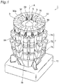
- FIG. 1 is a schematic perspective view of a combination weighing apparatus according to an embodiment.
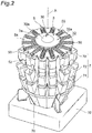
- FIG. 2 is a schematic perspective view in a case where a guide ring of the combination weighing apparatus illustrated in FIG. 1 is omitted.
- a combination weighing apparatus 1 illustrated in FIG. 1 and FIG. 2 weighs out the weighed object, each of which has a different mass, so that a total mass is within an acceptable range.
- the weighed object includes raw meat such as beef, pork, and chicken.
- the combination weighing apparatus 1 of the present embodiment can preferably weigh articles having adhesiveness in particular.
- the combination weighing apparatus 1 includes a distributing table (distributing portion) 3, a plurality of conveying portions 5, a plurality of hoppers 7, and a guide ring 9.
- the distributing table 3, the conveying portions 5, the hoppers 7, and the guide ring 9 are supported by a frame 10.
- FIG. 3 is a perspective view illustrating the distributing table and the conveying portions.
- the distributing table 3 is in a circular shape in a plan view.
- the distributing table 3 has a first distributing portion 30 and a second distributing portion 32.
- the first distributing portion 30 is in a cone shape with its center positioned at a central axis A.
- the first distributing portion 30 has a conveying face (outside face) 30a.
- the first distributing portion 30 is connected to the second distributing portion 32 on its bottom portion.
- the second distributing portion 32 is in a shape of cone that has a vertex angle larger than that of the first distributing portion 30 whose vertex portion is removed. At a position that corresponds to the removed vertex portion, the second distributing portion 32 is connected to the first distributing portion 30.
- a conveying face 32a of the second distributing portion 32 is different in inclination from the conveying face 30a of the first distributing portion 30. Due to this, an inclination of a conveying face 3a of the distributing table 3 changes at a connection portion of the first distributing portion 30 and the second distributing portion 32.
- the distributing table 3 is attached to a rotating axis 6 (refer to FIG. 4 ) supported by a supporting portion 4 (refer to FIG. 4 ).
- the distributing table 3 is detachable with respect to the rotating axis 6.
- a motor that is not illustrated here drives the rotating axis 6.
- the distributing table 3 rotates (normal and reverse rotations) around the central axis A by the motor. By rotating around the central axis A, the distributing table 3 conveys (distributes) in a direction towards an outer edge portion 3e of the conveying face 3a of the distributing table 3 the weighed object that is fed on the distributing table 3.
- FIG. 4 is a perspective view illustrating the conveying portion.
- the conveying portion 5 is made up of a trough 52 and a screw 54 arranged in the trough 52.
- the plurality of troughs 52 are formed on a trough plate 50.
- the trough plate 50 is in a circular shape in a plan view.
- An inner diameter of the trough plate 50 is substantially equal to an outer diameter of the supporting portion 4 and is smaller than an outer diameter of the distributing table 3.
- An inner circumference edge of the trough plate 50 is positioned inward than the outer edge portion 3e of the distributing table 3 when seen from the above along the central axis A.
- the trough 52 is a concave portion (concave shaped groove) in a semicircular column shape.
- the trough 52 is arranged in a radial manner from the center (the central axis A) of the trough plate 50.
- the trough 52 extends from the center to an outer edge of the trough plate 50.
- a connecting portion 56 that connects the troughs 52 is arranged between the troughs 52 adjacent to each other in a circumferential direction of the trough plate 50.
- the connecting portion 56 is in a triangle shape in which the inner circumference edge side is the vertex.
- the connecting portion 56 has a flat face.
- Each of the connecting portions 56 has a plurality of (three in this case) engaging bosses 58 for engaging the guide ring 9.
- the screw 54 is arranged in each of the troughs 52.
- a motor (not illustrated) arranged inside a wall portion 4a corresponding to the trough 52 in the supporting portion 4, the screw 54 is driven and rotates.
- the conveying portion 5, which is made up of the trough 52 and the screw 54, is arranged in a radial manner along the outer edge portion 3e of the distributing table 3. Then the conveying portion 5 conveys along the trough 52 by the screw 54 that is rotating the weighed object discharged from the distributing table 3.
- An edge portion of the distributing table 3 side of the conveying portion 5 is an introducing portion 59 for the weighed object.
- the hopper 7 is provided corresponding to each of the conveying portions 5. Then the hopper 7 receives the weighed object that has been discharged from the conveying portion 5. More specifically, the hopper 7 includes a pool hopper 70, a weighing hopper 72, and a booster hopper 74. The pool hopper 70, the weighing hopper 72, and the booster hopper 74 are arranged in this order from an upper side to a lower side.
- the pool hopper 70 temporarily holds the weighed object that has been discharged from the conveying portion 5.
- the weighing hopper 72 temporarily holds the weighed object that has been discharged from the pool hopper 70.
- the weighing hopper 72 is connected with a weighing apparatus that is not illustrated. Then this weighing apparatus weighs mass of the weighed object.
- the booster hopper 74 temporarily holds the weighed object that has been discharged from the weighing hopper 72.
- the set of the pool hopper 70, the weighing hopper 72, and the booster hopper 74 is arranged corresponding to each of the conveying portions 5.
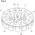
- FIG. 5 is a perspective view illustrating the guide ring.
- the guide ring 9 includes a plurality of guide blocks 90 arranged in a radial manner along the outer edge portion 3e of the distributing table 3.
- the guide block 90 is in a triangle shape that has an edge portion 92 (vertex portion) on the outer edge portion 3e side of the distributing table 3 in a plan view.
- a connecting portion 93 connects the guide blocks 90 adjacent to each other.
- An edge face 92a of the edge portion 92 is a flat face.
- a lower portion of the edge portion 92 of the guide block 90 is provided with a projecting portion 94 that projects inward than the edge face 92a.
- An upper face 94a of the projecting portion 94 is a flat face.
- the guide block 90 is arranged on the connecting portion 56 of the trough plate 50.
- the engaging boss 58 of the connecting portion 56 is fitted in an engaging hole (not illustrated) provided on a bottom face of the guide block 90.
- the guide block 90 is engaged in the connecting portion 56 of the trough plate 50.
- the distributing table 3 is attached to the rotating axis 6.
- the projecting portion 94 of the guide block 90 is positioned inward than the outer edge portion 3e of the distributing table 3 when seen from the above along the central axis A. As illustrated in FIG. 6 , there is a gap formed between the edge face 92a of the edge portion 92 of the guide block 90 and the outer edge portion 3e of the distributing table 3.
- the guide block 90 Since the guide block 90 is arranged on the trough plate 50, side walls 90a of the guide blocks 90 adjacent to each other form an area that has a width corresponding to a width of the trough 52 on each of the conveying portions 5.
- the edge portion 92 of the guide block 90 forms the introducing portion (introducing opening) 59 through which the weighed object to the conveying portions 5. This allows the weighed object that is conveyed by the distributing table 3 to be guided to the conveying portions 5 by the guide block 90 and thus introduced into the conveying portions 5.
- FIG. 7 is a view illustrating a cross sectional configuration of the outer edge portion of the distributing table.
- the distributing table 3 is provided with a projecting portion 40.
- the projecting portion 40 is arranged lower than the conveying face 3a.
- the projecting portion 40 is provided over the entire circumference of the outer edge portion 3e of the distributing table 3. The projecting portion 40 prevents the weighed object that is conveyed by the distributing table 3 from entering into the inside of the distributing table 3.
- the projecting portion 40 includes a first extending portion 42, a second extending portion 44, and a connecting portion 46.
- the first extending portion 42 extends downward from the outer edge portion 3e of the conveying face 3a of the distributing table 3.
- the first extending portion 42 extends along the central axis A.
- the second extending portion 44 is provided in a lower end portion of the first extending portion 42.
- the second extending portion 44 extends from the lower end portion of the first extending portion 42 to the inside of the distributing table 3.
- the second extending portion 44 extends along a horizontal direction.
- the connecting portion 46 connects an edge portion inside of the second extending portion 44 with an inside face 3b (inside face 32b) of the distributing table 3 (second distributing portion 32).
- the connecting portion 46 extends at a substantially right angle with respect to the second extending portion 44 (along the central axis A).
- a lower edge of the projecting portion 40 (a lower face 44a of the second extending portion 44) is at a same height as an upper face 4b of the supporting portion 4.
- a position of the lower edge of the projecting portion 40 may be set as appropriate in accordance with a design request desired by a designer.
- FIG. 8 is a view illustrating a cross sectional configuration of the distributing table and the guide block.
- FIG. 9 is a view illustrating a cross sectional configuration of the distributing table and the conveying portion.
- a first spacer member 60 is arranged between a side face 42a outside the first extending portion 42 and the edge face 92a of the edge portion 92 of the guide block 90.
- the first spacer member 60 is a plate-like member.
- the first spacer member 60 is formed of, for example, an abrasion-resistant resin or the like.
- a side face 60a of the first spacer member 60 and the side face 42a of the first extending portion 42 contact each other.
- An upper edge portion of the first spacer member 60 is positioned at a height of the conveying face 3a in the outer edge portion 3e of the distributing table 3.
- a second spacer member 62 is arranged between the lower face 44a of the second extending portion 44 and the upper face 94a of the projecting portion 94 of the guide block 90.
- the second spacer member 62 is a plate-like member.
- the second spacer member 62 is formed of, for example, an abrasion-resistant resin or the like.
- the second spacer member 62 is in a circular shape. That is, the second spacer member 62 is positioned in the conveying portion 5 and the guide block 90 as illustrated in FIG. 8 and FIG. 9 .
- the second spacer member 62 is arranged on the projecting portion 94 of each of the guide blocks 90. As illustrated in FIG. 9 , the second spacer member 62 is positioned above the screw 54 in the conveying portion 5.
- a third spacer member 64 is arranged at a position opposite to a side face 46a inside the connecting portion 46.
- the third spacer member 64 is a plate-like member.
- the third spacer member 64 is formed of, for example, an abrasion-resistant resin or the like.
- the third spacer member 64 is in a circular shape. That is, the third spacer member 64 is positioned in the conveying portion 5 and the guide block 90.
- the third spacer member 64 is fixed to the second spacer member 62.
- a side face 64a of the third spacer member 64 and the side face 46a of the connecting portion 46 contact each other.
- the weighed object (chicken for instance) is supplied by being dropped on a central portion of the distributing table 3 from above the distributing table 3.
- the distributing table 3 is rotating driven by the motor. Due to this, the weighed object supplied to the distributing table 3 is conveyed towards the outer edge portion 3e of the distributing table 3 and discharged from the outer edge portion 3e of the distributing table 3.
- the weighed object discharged from the distributing table 3 is introduced to the conveying portion 5 through the introducing portion 59 of the conveying portion 5 while being guided by the guide block 90.
- the weighed object introduced to the conveying portion 5 is conveyed along the trough 52 by the screw 54 that is intermittently driven by the motor and rotates. Then the weighed object is discharged from the conveying portion 5 so that it drops from an edge portion of the trough 52.
- the weighed object discharged from the conveying portion 5 is housed and temporarily held in the pool hopper 70 and then discharged from the pool hopper 70.
- the weighed object discharged from the pool hopper 70 is housed and temporarily held in the weighing hopper 72. At this moment, the weighing apparatus weighs a weight. After that, the weighed object discharged from the weighing hopper 72 is housed and temporarily held in the booster hopper 74.
- a computer calculates a combination of the hoppers 7 that realizes a weight value that matches a target weight (or a weight value that is the closest to a target weight) among all of the weighing hoppers 72 and the booster hoppers 74 that house the weighed object therein.
- the weighed object in one or a plurality of hoppers 7 that have been selected is discharged to a collecting chute 76.
- the weighed object collected to the collecting chute 76 is discharged towards a downstream apparatus that is not illustrated.
- the distributing table 3 is provided with the projecting portion 40 at a lower portion of the conveying face 3a in the outer edge portion 3e of the conveying face 3a.
- This projecting portion 40 makes it difficult for the weighed object to enter an inside of the distributing table 3.
- the combination weighing apparatus 1 can prevent the weighed object from remaining.
- the projecting portion 40 includes the first extending portion 42 that extends downwardly from the outer edge portion 3e of the conveying face 3a and the second extending portion 44 that extends from the lower end portion of the first extending portion 42 to an inside of the distributing table 3. This makes it more difficult for the weighed object to enter the inside of the distributing table 3.
- the projecting portion 40 includes the connecting portion 46 that connects the second extending portion 44 with the inside face 3b of the distributing table 3. This ensures a rigidity of the projecting portion 40. As a result, damage or the like of the projecting portion 40 can be prevented.
- the present embodiment includes the first spacer member 60 arranged in a position opposite to the side face 40a of an outside of the first extending portion 42. This allows the first spacer member 60 to fill a gap if there is the gap generated between the first extending portion 42 and the edge portion 92 of the guide block 90 arranged in a position opposite to the first extending portion 42. Therefore, the first spacer member 60 can prevent the weighed object from entering the gap. Consequently, the combination weighing apparatus 1 can prevent the weighed object from remaining.
- the present embodiment includes the second spacer member 62 arranged in a position opposite to the lower face 44a of the second extending portion 44.
- the lower face 44a of the second extending portion 44 and the upper face 62a of the second spacer member 62 are contacting each other.
- the second extending portion 44 and the second spacer member 62 contact each other; therefore, the weighed object is made more difficult to enter the inside of the distributing table 3.
- the present embodiment includes the third spacer member 64 arranged in a position opposite to the side face 46a of an inside of the connecting portion 46. As illustrated in FIG. 8 and FIG. 9 , the second spacer member 62 and the third spacer member 64 block an intrusion opening through which the weighed object intrudes between the upper face 4b of the supporting portion 4 and the distributing table 3. Therefore, the weighed object is made more difficult to enter the inside of the distributing table 3.
- the distributing table 3 conveys the weighed object by rotating.
- the weighed object is pulled into the inside by the rotation of the the distributing table 3 and remains. Since the distributing table 3 includes the projecting portion 40, it can prevent the weighed object from being pulled. Therefore, the projecting portion 40 is particularly effective in the configuration in which the distributing table 3 rotates.
- the conveying portion 5 conveys the weighed object by the screw 54 that rotates. This enables the conveying portion 5 to securely convey the weighed object that has a variety of forms. In particular, in a case where the weighed object has adhesiveness such as raw meat, it is preferably conveyed by the screw 54.
- a projecting portion 40A extends downwardly from the outer edge portion 3e of the distributing table 3 and includes only a portion that corresponds to the first extending portion 42 of the embodiment described above. In other words, the second extending portion and the connecting part may not be provided.
- a projecting portion 40B includes the first extending portion 42 and the second extending portion 44. In other words, the connecting part may not be provided.
- the supporting portion 4 may be provided with an extending portion 4c that extends from the wall portion 4a to the projecting portion 40A.
- the extending portion 4c is fixed to the wall portion 4a of the supporting portion 4 and provided over the entire circumference of the supporting portion 4.
- a tip of the extending portion 4c contacts an inside face 40Aa of the projecting portion 40A.
- the projecting portion 40A and the extending portion 4c make it difficult for the weighed object to enter the inside of the distributing table 3.
- the extending portion 4c may be provided in a configuration in which the distributing table 3 includes the projecting portion 40 of the embodiment described above. In this case, the extending portion 4c may be provided so that the lower face 44a of the second extending portion 44 contacts an upper face 4s of the extending portion 4c.
- the upper edge portion of the first spacer member 60 may be positioned above the conveying face 3a in the outer edge portion 3e of the distributing table 3 or may be positioned below the conveying face 3a.
- the first extending portion 42 may incline with respect to the central axis A.
- the second extending portion 44 may also incline with respect to a horizontal direction.
- the distributing table 3 may be in a form in which the weighed object is conveyed towards the outer edge portion 3e by vibration.
- a conveying method in the conveying portion 5 may be another method.
- the guide blocks 90 may not be connected with each other.
- the configuration of the distributing table 3 is not limited to it.
- first spacer member 60, the second spacer member 62, and the third spacer member 64 are formed of an abrasion-resistant resin or the like.
- first spacer member 60, the second spacer member 62, and the third spacer member 64 may be made up of another material with the surfaces of the first spacer member 60, the second spacer member 62, and the third spacer member 64 being coated with an abrasion-resistant material. It is more preferred that a coating material has a small coefficient of friction.
Landscapes
- Physics & Mathematics (AREA)
- General Physics & Mathematics (AREA)
- Engineering & Computer Science (AREA)
- Mechanical Engineering (AREA)
- Chemical & Material Sciences (AREA)
- Chemical Kinetics & Catalysis (AREA)
- Filling Or Emptying Of Bunkers, Hoppers, And Tanks (AREA)
- Branching, Merging, And Special Transfer Between Conveyors (AREA)
- Auxiliary Methods And Devices For Loading And Unloading (AREA)
- Weight Measurement For Supplying Or Discharging Of Specified Amounts Of Material (AREA)
Description
- The present invention relates to a combination weighing apparatus.
- The patent literature 1 discloses a combination weighing apparatus. This combination weighing apparatus includes a distributing portion that rotates to convey a weighed object outward, a plurality of conveying portions arranged in a radial manner along a circumference of the distributing portion and convey the weighed object discharged from the distributing portion by a rotating screw, a plurality of hoppers that are provided corresponding to each conveying portion and receive the weighed object discharged from the conveying portion, and a plurality of weighing hoppers arranged below the plurality of hoppers.
- Patent Literature 1: Japanese Unexamined Patent Publication No.
2014-509290 - When the distributing portion conveys a weighed object, the weighed object may enter an inside of the distributing portion. In particular, in a case of weighed object having adhesiveness such as meat, when entering the inside of the distributing portion, the weighed object is not conveyed by the conveying portion and remains. In a combination weighing apparatus, when the weighed object remains, maintainability is lowered due to necessity of an operation for removing the weighed object. For a combination weighing apparatus, therefore, it is required to prevent the weighed object from remaining.
- The present invention is intended to provide a combination weighing apparatus that can prevent a weighed object from remaining.
- The combination weighing apparatus according to an aspect of the present invention includes a distributing portion that has a conveying face that conveys a weighed object and conveys the weighed object in a direction toward an outer edge portion of the conveying face and a plurality of conveying portions arranged in a radial manner along an outer edge portion of the distributing portion and convey the weighed object discharged from the distributing portion, in which the distributing portion is provided with a projecting portion lower than the conveying face in the outer edge portion of the conveying face.
- The distributing portion included in the combination weighing apparatus is provided with the projecting portion lower than the conveying face in the outer edge portion of the conveying face. This projecting portion makes it difficult for the weighed object to enter the inside of the distributing portion. As a result, the combination weighing apparatus can prevent the weighed object from remaining.
- In an embodiment, the projecting portion may have a first extending portion that extends downwardly from the outer edge portion of the conveying face and a second extending portion that extends from a lower end portion of the first extending portion to the inside of the distributing portion. This makes it more difficult for the weighed object to enter the inside of the distributing portion.
- In an embodiment, the projecting portion may have a connecting portion that connects the second extending portion with the inside face of the distributing portion. This ensures a rigidity of the projecting portion. As a result, damage or the like of the projecting portion can be prevented.
- In an embodiment, a first spacer member arranged in a position opposite to a side face of an outside of the first extending portion may be provided. This allows the first spacer member to fill a gap if there is the gap generated between the projecting portion and a member arranged in a position opposite to the projecting portion. Therefore, the first spacer member can prevent the weighed object from entering the gap. Consequently, the combination weighing apparatus can prevent the weighed object from remaining.
- In an embodiment, a second spacer member arranged in a position opposite to a bottom face of the second extending portion is provided and the bottom face of the second extending portion may contact a top face of the second spacer member. By thus contacting the second extending portion with the second spacer member, the weighed object becomes more difficult to enter the inside of the distributing portion.
- In an embodiment, a third spacer member arranged in a position opposite to a side face of an inside of the connecting portion may be provided. This makes it more difficult for the weighed object to enter the inside of the distributing portion.
- In an embodiment, the distributing portion may convey the weighed object by rotating. In a case where the distributing portion rotates, the weighed object is liable to be pulled into the inside by the rotation of the distributing portion and remains. Since the distributing portion includes the projecting portion, it can prevent the weighed object from being pulled. Therefore, the projecting portion is particularly effective in a configuration in which the distributing portion rotates.
- In an embodiment, the conveying portion may convey the weighed object by the rotating screw. This enables the conveying portion to securely convey the weighed object that has a variety of forms.
- In an embodiment, the weighed object may have adhesiveness. In a case where the weighed object has adhesiveness, the weighed object is in particular liable to remain because it adheres to the inside of the distributing portion when entering the inside of the distributing portion. Therefore, the configuration of the distributing portion that has the projecting portion is effective particularly in a case of weighing the weighed object that has adhesiveness. It is to be noted that the weighed object that has adhesiveness includes meat.
- The present invention can prevent the weighed object from remaining.
-
-
FIG. 1 is a schematic perspective view of a combination weighing apparatus according to an embodiment. -
FIG. 2 is a schematic perspective view in a case where a guide ring of the combination weighing apparatus illustrated inFIG. 1 is omitted. -
FIG. 3 is a perspective view illustrating a distributing table and a conveying portion. -
FIG. 4 is a perspective view illustrating the conveying portion. -
FIG. 5 is a perspective view illustrating the guide ring. -
FIG. 6 is an upper view of the combination weighing apparatus illustrated inFIG. 1 . -
FIG. 7 is a view illustrating a cross sectional configuration of an outer edge portion of the distributing table. -
FIG. 8 is a view illustrating a cross sectional configuration of the distributing table and a guide block. -
FIG. 9 is a view illustrating a cross sectional configuration of the distributing table and the conveying portion. -
FIG. 10 is a view illustrating a cross sectional configuration of the outer edge portion of the distributing table according to another embodiment. -
FIG. 11 is a view illustrating a cross sectional configuration of the distributing table and the conveying portion according to another embodiment. -
FIG. 12 is a view illustrating a cross sectional configuration of the distributing table and the conveying portion according to another embodiment. - A detailed description of a preferred embodiment of the present invention will now be given with reference to the drawings. It is to be noted that in the description of the drawings, identical or corresponding elements are designated by the same reference numerals and overlapping descriptions will be curtailed.
-
FIG. 1 is a schematic perspective view of a combination weighing apparatus according to an embodiment. -
FIG. 2 is a schematic perspective view in a case where a guide ring of the combination weighing apparatus illustrated inFIG. 1 is omitted. - A combination weighing apparatus 1 illustrated in
FIG. 1 andFIG. 2 weighs out the weighed object, each of which has a different mass, so that a total mass is within an acceptable range. Here, the weighed object includes raw meat such as beef, pork, and chicken. The combination weighing apparatus 1 of the present embodiment can preferably weigh articles having adhesiveness in particular. - As illustrated in
FIG. 1 andFIG. 2 , the combination weighing apparatus 1 includes a distributing table (distributing portion) 3, a plurality of conveyingportions 5, a plurality ofhoppers 7, and aguide ring 9. The distributing table 3, the conveyingportions 5, thehoppers 7, and theguide ring 9 are supported by aframe 10. -
FIG. 3 is a perspective view illustrating the distributing table and the conveying portions. As illustrated inFIG. 1 to FIG. 3 , the distributing table 3 is in a circular shape in a plan view. The distributing table 3 has a first distributingportion 30 and a second distributingportion 32. The first distributingportion 30 is in a cone shape with its center positioned at a central axis A. The first distributingportion 30 has a conveying face (outside face) 30a. The first distributingportion 30 is connected to the second distributingportion 32 on its bottom portion. - The second distributing
portion 32 is in a shape of cone that has a vertex angle larger than that of the first distributingportion 30 whose vertex portion is removed. At a position that corresponds to the removed vertex portion, the second distributingportion 32 is connected to the first distributingportion 30. A conveyingface 32a of the second distributingportion 32 is different in inclination from the conveyingface 30a of the first distributingportion 30. Due to this, an inclination of a conveyingface 3a of the distributing table 3 changes at a connection portion of the first distributingportion 30 and the second distributingportion 32. - The distributing table 3 is attached to a rotating axis 6 (refer to
FIG. 4 ) supported by a supporting portion 4 (refer toFIG. 4 ). The distributing table 3 is detachable with respect to therotating axis 6. A motor that is not illustrated here drives therotating axis 6. The distributing table 3 rotates (normal and reverse rotations) around the central axis A by the motor. By rotating around the central axis A, the distributing table 3 conveys (distributes) in a direction towards anouter edge portion 3e of the conveyingface 3a of the distributing table 3 the weighed object that is fed on the distributing table 3. -
FIG. 4 is a perspective view illustrating the conveying portion. As illustrated inFIG. 2 to FIG. 4 , the conveyingportion 5 is made up of atrough 52 and ascrew 54 arranged in thetrough 52. The plurality oftroughs 52 are formed on atrough plate 50. Thetrough plate 50 is in a circular shape in a plan view. An inner diameter of thetrough plate 50 is substantially equal to an outer diameter of the supportingportion 4 and is smaller than an outer diameter of the distributing table 3. An inner circumference edge of thetrough plate 50 is positioned inward than theouter edge portion 3e of the distributing table 3 when seen from the above along the central axis A. - The
trough 52 is a concave portion (concave shaped groove) in a semicircular column shape. Thetrough 52 is arranged in a radial manner from the center (the central axis A) of thetrough plate 50. Thetrough 52 extends from the center to an outer edge of thetrough plate 50. - Here, a connecting
portion 56 that connects thetroughs 52 is arranged between thetroughs 52 adjacent to each other in a circumferential direction of thetrough plate 50. The connectingportion 56 is in a triangle shape in which the inner circumference edge side is the vertex. In addition the connectingportion 56 has a flat face. Each of the connectingportions 56 has a plurality of (three in this case) engagingbosses 58 for engaging theguide ring 9. - The
screw 54 is arranged in each of thetroughs 52. By a motor (not illustrated) arranged inside awall portion 4a corresponding to thetrough 52 in the supportingportion 4, thescrew 54 is driven and rotates. The conveyingportion 5, which is made up of thetrough 52 and thescrew 54, is arranged in a radial manner along theouter edge portion 3e of the distributing table 3. Then the conveyingportion 5 conveys along thetrough 52 by thescrew 54 that is rotating the weighed object discharged from the distributing table 3. An edge portion of the distributing table 3 side of the conveyingportion 5 is an introducingportion 59 for the weighed object. - As illustrated in
FIG. 1 andFIG. 2 , thehopper 7 is provided corresponding to each of the conveyingportions 5. Then thehopper 7 receives the weighed object that has been discharged from the conveyingportion 5. More specifically, thehopper 7 includes apool hopper 70, a weighinghopper 72, and abooster hopper 74. Thepool hopper 70, the weighinghopper 72, and thebooster hopper 74 are arranged in this order from an upper side to a lower side. - The
pool hopper 70 temporarily holds the weighed object that has been discharged from the conveyingportion 5. The weighinghopper 72 temporarily holds the weighed object that has been discharged from thepool hopper 70. The weighinghopper 72 is connected with a weighing apparatus that is not illustrated. Then this weighing apparatus weighs mass of the weighed object. Thebooster hopper 74 temporarily holds the weighed object that has been discharged from the weighinghopper 72. In the above, the set of thepool hopper 70, the weighinghopper 72, and thebooster hopper 74 is arranged corresponding to each of the conveyingportions 5. -
FIG. 5 is a perspective view illustrating the guide ring. As illustrated inFIG. 1 andFIG. 5 , theguide ring 9 includes a plurality of guide blocks 90 arranged in a radial manner along theouter edge portion 3e of the distributing table 3. Theguide block 90 is in a triangle shape that has an edge portion 92 (vertex portion) on theouter edge portion 3e side of the distributing table 3 in a plan view. Here, a connectingportion 93 connects the guide blocks 90 adjacent to each other. Anedge face 92a of theedge portion 92 is a flat face. A lower portion of theedge portion 92 of theguide block 90 is provided with a projectingportion 94 that projects inward than theedge face 92a. Anupper face 94a of the projectingportion 94 is a flat face. - The
guide block 90 is arranged on the connectingportion 56 of thetrough plate 50. At this time, the engagingboss 58 of the connectingportion 56 is fitted in an engaging hole (not illustrated) provided on a bottom face of theguide block 90. As a result, theguide block 90 is engaged in the connectingportion 56 of thetrough plate 50. After theguide ring 9 is arranged on thetrough plate 50, the distributing table 3 is attached to therotating axis 6. The projectingportion 94 of theguide block 90 is positioned inward than theouter edge portion 3e of the distributing table 3 when seen from the above along the central axis A. As illustrated inFIG. 6 , there is a gap formed between theedge face 92a of theedge portion 92 of theguide block 90 and theouter edge portion 3e of the distributing table 3. - Since the
guide block 90 is arranged on thetrough plate 50,side walls 90a of the guide blocks 90 adjacent to each other form an area that has a width corresponding to a width of thetrough 52 on each of the conveyingportions 5. Theedge portion 92 of theguide block 90 forms the introducing portion (introducing opening) 59 through which the weighed object to the conveyingportions 5. This allows the weighed object that is conveyed by the distributing table 3 to be guided to the conveyingportions 5 by theguide block 90 and thus introduced into the conveyingportions 5. - Subsequently, the configuration of the distributing table 3 will be described in detail.
FIG. 7 is a view illustrating a cross sectional configuration of the outer edge portion of the distributing table. As illustrated inFIG. 7 , the distributing table 3 is provided with a projectingportion 40. In theouter edge portion 3e of the conveyingface 3a, the projectingportion 40 is arranged lower than the conveyingface 3a. The projectingportion 40 is provided over the entire circumference of theouter edge portion 3e of the distributing table 3. The projectingportion 40 prevents the weighed object that is conveyed by the distributing table 3 from entering into the inside of the distributing table 3. - The projecting
portion 40 includes a first extendingportion 42, a second extendingportion 44, and a connectingportion 46. The first extendingportion 42 extends downward from theouter edge portion 3e of the conveyingface 3a of the distributing table 3. The first extendingportion 42 extends along the central axis A. The second extendingportion 44 is provided in a lower end portion of the first extendingportion 42. The second extendingportion 44 extends from the lower end portion of the first extendingportion 42 to the inside of the distributing table 3. The second extendingportion 44 extends along a horizontal direction. The connectingportion 46 connects an edge portion inside of the second extendingportion 44 with aninside face 3b (insideface 32b) of the distributing table 3 (second distributing portion 32). The connectingportion 46 extends at a substantially right angle with respect to the second extending portion 44 (along the central axis A). - In the present embodiment, a lower edge of the projecting portion 40 (a
lower face 44a of the second extending portion 44) is at a same height as anupper face 4b of the supportingportion 4. A position of the lower edge of the projectingportion 40 may be set as appropriate in accordance with a design request desired by a designer. -
FIG. 8 is a view illustrating a cross sectional configuration of the distributing table and the guide block.FIG. 9 is a view illustrating a cross sectional configuration of the distributing table and the conveying portion. As illustrated inFig. 8 , afirst spacer member 60 is arranged between aside face 42a outside the first extendingportion 42 and theedge face 92a of theedge portion 92 of theguide block 90. Thefirst spacer member 60 is a plate-like member. Thefirst spacer member 60 is formed of, for example, an abrasion-resistant resin or the like. Aside face 60a of thefirst spacer member 60 and theside face 42a of the first extendingportion 42 contact each other. An upper edge portion of thefirst spacer member 60 is positioned at a height of the conveyingface 3a in theouter edge portion 3e of the distributing table 3. - A
second spacer member 62 is arranged between thelower face 44a of the second extendingportion 44 and theupper face 94a of the projectingportion 94 of theguide block 90. Thesecond spacer member 62 is a plate-like member. Thesecond spacer member 62 is formed of, for example, an abrasion-resistant resin or the like. Thesecond spacer member 62 is in a circular shape. That is, thesecond spacer member 62 is positioned in the conveyingportion 5 and theguide block 90 as illustrated inFIG. 8 andFIG. 9 . Thesecond spacer member 62 is arranged on the projectingportion 94 of each of the guide blocks 90. As illustrated inFIG. 9 , thesecond spacer member 62 is positioned above thescrew 54 in the conveyingportion 5. There is little gap formed between thesecond spacer member 62 and thescrew 54. That is, an upper edge of thescrew 54 and theupper face 94a of the projectingportion 94 of theguide block 90 are at the substantially same height. Anupper face 62a of thesecond spacer member 62 and thelower face 44a of the second extendingportion 44 contact each other. - A
third spacer member 64 is arranged at a position opposite to aside face 46a inside the connectingportion 46. Thethird spacer member 64 is a plate-like member. Thethird spacer member 64 is formed of, for example, an abrasion-resistant resin or the like. Thethird spacer member 64 is in a circular shape. That is, thethird spacer member 64 is positioned in the conveyingportion 5 and theguide block 90. Thethird spacer member 64 is fixed to thesecond spacer member 62. Aside face 64a of thethird spacer member 64 and theside face 46a of the connectingportion 46 contact each other. When the distributing table 3 rotates, the projectingportion 40 slides with respect to thefirst spacer member 60, thesecond spacer member 62, and thethird spacer member 64. - In the combination weighing apparatus 1, which has the above configuration, the weighed object (chicken for instance) is supplied by being dropped on a central portion of the distributing table 3 from above the distributing table 3. At this moment, the distributing table 3 is rotating driven by the motor. Due to this, the weighed object supplied to the distributing table 3 is conveyed towards the
outer edge portion 3e of the distributing table 3 and discharged from theouter edge portion 3e of the distributing table 3. The weighed object discharged from the distributing table 3 is introduced to the conveyingportion 5 through the introducingportion 59 of the conveyingportion 5 while being guided by theguide block 90. - The weighed object introduced to the conveying
portion 5 is conveyed along thetrough 52 by thescrew 54 that is intermittently driven by the motor and rotates. Then the weighed object is discharged from the conveyingportion 5 so that it drops from an edge portion of thetrough 52. The weighed object discharged from the conveyingportion 5 is housed and temporarily held in thepool hopper 70 and then discharged from thepool hopper 70. The weighed object discharged from thepool hopper 70 is housed and temporarily held in the weighinghopper 72. At this moment, the weighing apparatus weighs a weight. After that, the weighed object discharged from the weighinghopper 72 is housed and temporarily held in thebooster hopper 74. - Then, a computer calculates a combination of the
hoppers 7 that realizes a weight value that matches a target weight (or a weight value that is the closest to a target weight) among all of the weighinghoppers 72 and thebooster hoppers 74 that house the weighed object therein. The weighed object in one or a plurality ofhoppers 7 that have been selected is discharged to a collectingchute 76. The weighed object collected to the collectingchute 76 is discharged towards a downstream apparatus that is not illustrated. - As described so far, in the combination weighing apparatus 1 of the present embodiment, the distributing table 3 is provided with the projecting
portion 40 at a lower portion of the conveyingface 3a in theouter edge portion 3e of the conveyingface 3a. This projectingportion 40 makes it difficult for the weighed object to enter an inside of the distributing table 3. As a result, the combination weighing apparatus 1 can prevent the weighed object from remaining. - In the present embodiment, the projecting
portion 40 includes the first extendingportion 42 that extends downwardly from theouter edge portion 3e of the conveyingface 3a and the second extendingportion 44 that extends from the lower end portion of the first extendingportion 42 to an inside of the distributing table 3. This makes it more difficult for the weighed object to enter the inside of the distributing table 3. - In the present embodiment, the projecting
portion 40 includes the connectingportion 46 that connects the second extendingportion 44 with theinside face 3b of the distributing table 3. This ensures a rigidity of the projectingportion 40. As a result, damage or the like of the projectingportion 40 can be prevented. - The present embodiment includes the
first spacer member 60 arranged in a position opposite to the side face 40a of an outside of the first extendingportion 42. This allows thefirst spacer member 60 to fill a gap if there is the gap generated between the first extendingportion 42 and theedge portion 92 of theguide block 90 arranged in a position opposite to the first extendingportion 42. Therefore, thefirst spacer member 60 can prevent the weighed object from entering the gap. Consequently, the combination weighing apparatus 1 can prevent the weighed object from remaining. - The present embodiment includes the
second spacer member 62 arranged in a position opposite to thelower face 44a of the second extendingportion 44. Thelower face 44a of the second extendingportion 44 and theupper face 62a of thesecond spacer member 62 are contacting each other. Thus, the second extendingportion 44 and thesecond spacer member 62 contact each other; therefore, the weighed object is made more difficult to enter the inside of the distributing table 3. - The present embodiment includes the
third spacer member 64 arranged in a position opposite to theside face 46a of an inside of the connectingportion 46. As illustrated inFIG. 8 andFIG. 9 , thesecond spacer member 62 and thethird spacer member 64 block an intrusion opening through which the weighed object intrudes between theupper face 4b of the supportingportion 4 and the distributing table 3. Therefore, the weighed object is made more difficult to enter the inside of the distributing table 3. - In the present embodiment, the distributing table 3 conveys the weighed object by rotating. In a case where the distributing table 3 rotates, the weighed object is pulled into the inside by the rotation of the the distributing table 3 and remains. Since the distributing table 3 includes the projecting
portion 40, it can prevent the weighed object from being pulled. Therefore, the projectingportion 40 is particularly effective in the configuration in which the distributing table 3 rotates. - In the present embodiment, the conveying
portion 5 conveys the weighed object by thescrew 54 that rotates. This enables the conveyingportion 5 to securely convey the weighed object that has a variety of forms. In particular, in a case where the weighed object has adhesiveness such as raw meat, it is preferably conveyed by thescrew 54. - The present invention is not limited to the embodiments described above. While in the embodiment described above, the description has been made with an example of the form in which the projecting
portion 40 includes the first extendingportion 42, the second extendingportion 44, and the connectingportion 46, the configuration of the projecting portion is not limited to it. As illustrated inFIG. 10(a) , a projectingportion 40A extends downwardly from theouter edge portion 3e of the distributing table 3 and includes only a portion that corresponds to the first extendingportion 42 of the embodiment described above. In other words, the second extending portion and the connecting part may not be provided. In addition, as illustrated inFIG. 10(b) , a projectingportion 40B includes the first extendingportion 42 and the second extendingportion 44. In other words, the connecting part may not be provided. - As illustrated in
FIG. 11 , the supportingportion 4 may be provided with an extendingportion 4c that extends from thewall portion 4a to the projectingportion 40A. The extendingportion 4c is fixed to thewall portion 4a of the supportingportion 4 and provided over the entire circumference of the supportingportion 4. A tip of the extendingportion 4c contacts an inside face 40Aa of the projectingportion 40A. In accordance with this configuration, the projectingportion 40A and the extendingportion 4c make it difficult for the weighed object to enter the inside of the distributing table 3. In addition, as illustrated inFIG. 12 , the extendingportion 4c may be provided in a configuration in which the distributing table 3 includes the projectingportion 40 of the embodiment described above. In this case, the extendingportion 4c may be provided so that thelower face 44a of the second extendingportion 44 contacts anupper face 4s of the extendingportion 4c. - In the embodiment described above, the description has been made with an example of the form in which the upper edge portion of the
first spacer member 60 is positioned at a height of the conveyingface 3a in theouter edge portion 3e of the distributing table 3. However, the upper edge portion of thefirst spacer member 60 may be positioned above the conveyingface 3a in theouter edge portion 3e of the distributing table 3 or may be positioned below the conveyingface 3a. - In the embodiment described above, the description has been made with an example of the form in which the first extending
portion 42 extends along the central axis A. However, the first extendingportion 42 may incline with respect to the central axis A. The second extendingportion 44 may also incline with respect to a horizontal direction. - In the embodiment described above, the description has been made with an example of the form in which the distributing table 3 rotates about the central axis A so that the weighed object is conveyed towards the
outer edge portion 3e. However, the distributing table 3 may be in a form in which the weighed object is conveyed towards theouter edge portion 3e by vibration. - In the embodiment described above, the description has been made with an example of the form in which the weighed object is conveyed by the
screw 54 in the conveyingportion 5. However, a conveying method in the conveyingportion 5 may be another method. - In the embodiment described above, the description has been made with an example of the form in which the guide blocks 90 are connected with each other by the connecting
portion 93 in theguide ring 9. However, the guide blocks 90 may not be connected with each other. - While in the embodiment described above, the description has been made with an example of the form in which the distributing table 3 includes the first distributing
portion 30 and the second distributingportion 32, the configuration of the distributing table 3 is not limited to it. - In the embodiment described above, the description has been made with an example of the form in which the
first spacer member 60, thesecond spacer member 62, and thethird spacer member 64 are formed of an abrasion-resistant resin or the like. However, thefirst spacer member 60, thesecond spacer member 62, and thethird spacer member 64 may be made up of another material with the surfaces of thefirst spacer member 60, thesecond spacer member 62, and thethird spacer member 64 being coated with an abrasion-resistant material. It is more preferred that a coating material has a small coefficient of friction. -
- 1: combination weighing apparatus, 3: distributing table (distributing portion), 3a: conveying face, 3e: outer edge portion, 5: conveying portion, 40, 40A, 40B: projecting portion, 42: first extending portion, 42a: side face, 44: second extending portion, 44a: lower face, 46: connecting portion, 46a: side face, 54: screw, 60: first spacer member, 62: second spacer member, 62a: upper face, 64: third spacer member
Claims (9)
- A combination weighing apparatus, comprising: a distributing portion that includes a conveying face that conveys a weighed object and conveys the weighed object in a direction towards an outer edge portion of the conveying face and a plurality of conveying portions arranged in a radial manner along the outer edge portion of the distributing portion and convey the weighed object discharged from the distributing portion, wherein: the distributing portion is provided with a projecting portion lower than the conveying face in the outer edge portion of the conveying face.
- The combination weighing apparatus according to claim 1, wherein the projecting portion includes a first extending portion that extends downwardly from the outer edge portion of the conveying face and a second extending portion that extends from a lower end portion of the first extending portion to an inside of the distributing portion.
- The combination weighing apparatus according to claim 2, wherein the projecting portion includes a connecting portion that connects the second extending portion with an inside face of the distributing portion.
- The combination weighing apparatus according to claim 2 or 3, comprising a first spacer member arranged in a position opposite to a side face of an outside of the first extending portion.
- The combination weighing apparatus according to any one of claims 2 to 4, comprising a second spacer member arranged in a position opposite to a lower face of the second extending portion, wherein the lower face of the second extending portion and an upper face of the second spacer member contact each other.
- The combination weighing apparatus according to claim 3, comprising a third spacer member arranged in a position opposite to a side face of an inside of the connecting portion.
- The combination weighing apparatus according to any one of claims 1 to 6, wherein the distributing portion conveys the weighed object by rotating.
- The combination weighing apparatus according to any one of claims 1 to 7, wherein the conveying portion conveys the weighed object by a screw that rotates.
- The combination weighing apparatus according to any one of claims 1 to 8, wherein the weighed object has adhesiveness.
Applications Claiming Priority (2)
| Application Number | Priority Date | Filing Date | Title |
|---|---|---|---|
| JP2014148046A JP6389387B2 (en) | 2014-07-18 | 2014-07-18 | Combination weighing device |
| PCT/JP2015/069512 WO2016009895A1 (en) | 2014-07-18 | 2015-07-07 | Combination weighing device |
Publications (3)
| Publication Number | Publication Date |
|---|---|
| EP3171140A1 true EP3171140A1 (en) | 2017-05-24 |
| EP3171140A4 EP3171140A4 (en) | 2018-02-14 |
| EP3171140B1 EP3171140B1 (en) | 2019-09-18 |
Family
ID=55078391
Family Applications (1)
| Application Number | Title | Priority Date | Filing Date |
|---|---|---|---|
| EP15821298.5A Active EP3171140B1 (en) | 2014-07-18 | 2015-07-07 | Combination weighing device |
Country Status (7)
| Country | Link |
|---|---|
| US (1) | US20170211967A1 (en) |
| EP (1) | EP3171140B1 (en) |
| JP (1) | JP6389387B2 (en) |
| BR (1) | BR112017000986B1 (en) |
| DK (1) | DK3171140T3 (en) |
| RU (1) | RU2663685C1 (en) |
| WO (1) | WO2016009895A1 (en) |
Families Citing this family (3)
| Publication number | Priority date | Publication date | Assignee | Title |
|---|---|---|---|---|
| WO2017110558A1 (en) * | 2015-12-24 | 2017-06-29 | 株式会社イシダ | Dispersive supply device and combination weighing device |
| US10723492B2 (en) * | 2017-09-21 | 2020-07-28 | Yamato Corporation | Depositor apparatus |
| JP2024126447A (en) * | 2023-03-07 | 2024-09-20 | 株式会社イシダ | Dispersion supply device and combination weighing device equipped with same |
Family Cites Families (15)
| Publication number | Priority date | Publication date | Assignee | Title |
|---|---|---|---|---|
| JPS62102126U (en) * | 1985-12-17 | 1987-06-29 | ||
| JPH0518669Y2 (en) * | 1987-10-09 | 1993-05-18 | ||
| JP2671657B2 (en) * | 1991-04-22 | 1997-10-29 | 富士電機株式会社 | Polymer sensor |
| JPH055724U (en) * | 1991-07-12 | 1993-01-26 | アンリツ株式会社 | Distributed feeder |
| EP1698868A1 (en) * | 2005-03-03 | 2006-09-06 | Cabinplant International A/S | Weighing arrangement |
| KR101374132B1 (en) * | 2005-12-08 | 2014-03-14 | 에프비씨디바이스 에이피에스 | Disc implant |
| US7732718B2 (en) * | 2008-05-09 | 2010-06-08 | Ishida Co., Ltd. | Combination weighing apparatus with conveying unit including trough and spiral member |
| JP5102100B2 (en) * | 2008-05-09 | 2012-12-19 | 株式会社イシダ | Combination weighing device |
| US7790990B2 (en) * | 2008-10-30 | 2010-09-07 | Yamato Corporation | Combination weigher with peripheral annular recycling table |
| JP2011209156A (en) * | 2010-03-30 | 2011-10-20 | Ishida Co Ltd | Combination weighing device |
| EP2484593A1 (en) * | 2011-02-04 | 2012-08-08 | Cabinplant International A/S | An apparatus for conveying and selectively discharging products |
| US20130186696A1 (en) * | 2012-01-25 | 2013-07-25 | Marel A/S | Combination weigher |
| RU121235U1 (en) * | 2012-05-24 | 2012-10-20 | Общество с ограниченной ответственностью "Внедренческое конструкторское предприятие "Сигнал-Пак" | COMBINATION DISPENSER |
| RU125696U1 (en) * | 2012-10-03 | 2013-03-10 | Закрытое акционерное общество "ТАУРАС-ФЕНИКС" (ЗАО "ТАУРАС-ФЕНИКС") | DOSING DEVICE |
| RU136787U1 (en) * | 2013-08-27 | 2014-01-20 | Закрытое акционерное общество "НОТИС" (ЗАО "НОТИС") | LOADING DEVICE OF COMBINATION DISPENSER |
-
2014
- 2014-07-18 JP JP2014148046A patent/JP6389387B2/en active Active
-
2015
- 2015-07-07 US US15/326,794 patent/US20170211967A1/en not_active Abandoned
- 2015-07-07 BR BR112017000986-2A patent/BR112017000986B1/en active IP Right Grant
- 2015-07-07 DK DK15821298T patent/DK3171140T3/en active
- 2015-07-07 EP EP15821298.5A patent/EP3171140B1/en active Active
- 2015-07-07 WO PCT/JP2015/069512 patent/WO2016009895A1/en not_active Ceased
- 2015-07-07 RU RU2017105075A patent/RU2663685C1/en active
Also Published As
| Publication number | Publication date |
|---|---|
| EP3171140B1 (en) | 2019-09-18 |
| DK3171140T3 (en) | 2019-11-18 |
| EP3171140A4 (en) | 2018-02-14 |
| BR112017000986B1 (en) | 2021-05-25 |
| US20170211967A1 (en) | 2017-07-27 |
| RU2663685C1 (en) | 2018-08-08 |
| JP6389387B2 (en) | 2018-09-12 |
| WO2016009895A1 (en) | 2016-01-21 |
| JP2016024037A (en) | 2016-02-08 |
| BR112017000986A2 (en) | 2017-11-14 |
Similar Documents
| Publication | Publication Date | Title |
|---|---|---|
| EP3171140B1 (en) | Combination weighing device | |
| EP3112825B1 (en) | Combination weighing apparatus | |
| US10094700B2 (en) | Conveyor apparatus and combined weighing apparatus | |
| AU2021203976B2 (en) | Methods and systems for weighing and collecting solid food products | |
| JP6793174B2 (en) | Parts control and distribution system | |
| EP3171141B1 (en) | Combination weighing device | |
| JP6305836B2 (en) | Article regulating device and combination weigher provided with the same | |
| EP4428503B1 (en) | Distribution supply apparatus and combination weighing apparatus including the same | |
| JP6157922B2 (en) | Combining scale article transport structure | |
| EP3385684B1 (en) | Combination weighing apparatus | |
| JP2015215271A (en) | Weighing device | |
| EP4417946A1 (en) | Weighing apparatus | |
| JPWO2016199870A1 (en) | Combination weighing device | |
| CN217026005U (en) | Repair steelmaking converter and throw material device with accurate material structure of throwing | |
| JP6305834B2 (en) | Article supply adjusting device and combination scale provided with the same | |
| DK201400122U3 (en) | The combination weighing device | |
| JP5345022B2 (en) | Combination weighing device | |
| US20240369396A1 (en) | Weighing device for a multi-head weighing machine, weighing head and multi-head weighing machine | |
| JP7212987B2 (en) | combination weigher | |
| JP2023133756A (en) | Combination weighing device | |
| JP2018158798A (en) | Quantitative feeder device for powder | |
| JP2009019939A (en) | Collective funnel for combination weigher | |
| JP2017133955A (en) | Combination weighing device | |
| CN110077822A (en) | Oil-can lid liner identifies loading plate automatically | |
| JP5855308B1 (en) | Combination weighing device |
Legal Events
| Date | Code | Title | Description |
|---|---|---|---|
| STAA | Information on the status of an ep patent application or granted ep patent |
Free format text: STATUS: THE INTERNATIONAL PUBLICATION HAS BEEN MADE |
|
| PUAI | Public reference made under article 153(3) epc to a published international application that has entered the european phase |
Free format text: ORIGINAL CODE: 0009012 |
|
| STAA | Information on the status of an ep patent application or granted ep patent |
Free format text: STATUS: REQUEST FOR EXAMINATION WAS MADE |
|
| 17P | Request for examination filed |
Effective date: 20170126 |
|
| AK | Designated contracting states |
Kind code of ref document: A1 Designated state(s): AL AT BE BG CH CY CZ DE DK EE ES FI FR GB GR HR HU IE IS IT LI LT LU LV MC MK MT NL NO PL PT RO RS SE SI SK SM TR |
|
| AX | Request for extension of the european patent |
Extension state: BA ME |
|
| DAV | Request for validation of the european patent (deleted) | ||
| DAX | Request for extension of the european patent (deleted) | ||
| REG | Reference to a national code |
Ref country code: DE Ref legal event code: R079 Ref document number: 602015038393 Country of ref document: DE Free format text: PREVIOUS MAIN CLASS: G01G0019387000 Ipc: G01G0019393000 |
|
| A4 | Supplementary search report drawn up and despatched |
Effective date: 20180117 |
|
| RIC1 | Information provided on ipc code assigned before grant |
Ipc: G01G 13/00 20060101ALI20180110BHEP Ipc: G01G 19/393 20060101AFI20180110BHEP Ipc: G01G 19/387 20060101ALI20180110BHEP Ipc: G01G 13/02 20060101ALI20180110BHEP |
|
| GRAP | Despatch of communication of intention to grant a patent |
Free format text: ORIGINAL CODE: EPIDOSNIGR1 |
|
| STAA | Information on the status of an ep patent application or granted ep patent |
Free format text: STATUS: GRANT OF PATENT IS INTENDED |
|
| INTG | Intention to grant announced |
Effective date: 20190402 |
|
| GRAS | Grant fee paid |
Free format text: ORIGINAL CODE: EPIDOSNIGR3 |
|
| GRAA | (expected) grant |
Free format text: ORIGINAL CODE: 0009210 |
|
| STAA | Information on the status of an ep patent application or granted ep patent |
Free format text: STATUS: THE PATENT HAS BEEN GRANTED |
|
| AK | Designated contracting states |
Kind code of ref document: B1 Designated state(s): AL AT BE BG CH CY CZ DE DK EE ES FI FR GB GR HR HU IE IS IT LI LT LU LV MC MK MT NL NO PL PT RO RS SE SI SK SM TR |
|
| REG | Reference to a national code |
Ref country code: GB Ref legal event code: FG4D |
|
| REG | Reference to a national code |
Ref country code: CH Ref legal event code: EP |
|
| REG | Reference to a national code |
Ref country code: NL Ref legal event code: FP |
|
| REG | Reference to a national code |
Ref country code: DE Ref legal event code: R096 Ref document number: 602015038393 Country of ref document: DE |
|
| REG | Reference to a national code |
Ref country code: AT Ref legal event code: REF Ref document number: 1181888 Country of ref document: AT Kind code of ref document: T Effective date: 20191015 |
|
| REG | Reference to a national code |
Ref country code: IE Ref legal event code: FG4D |
|
| REG | Reference to a national code |
Ref country code: DK Ref legal event code: T3 Effective date: 20191111 |
|
| PG25 | Lapsed in a contracting state [announced via postgrant information from national office to epo] |
Ref country code: LT Free format text: LAPSE BECAUSE OF FAILURE TO SUBMIT A TRANSLATION OF THE DESCRIPTION OR TO PAY THE FEE WITHIN THE PRESCRIBED TIME-LIMIT Effective date: 20190918 Ref country code: BG Free format text: LAPSE BECAUSE OF FAILURE TO SUBMIT A TRANSLATION OF THE DESCRIPTION OR TO PAY THE FEE WITHIN THE PRESCRIBED TIME-LIMIT Effective date: 20191218 Ref country code: NO Free format text: LAPSE BECAUSE OF FAILURE TO SUBMIT A TRANSLATION OF THE DESCRIPTION OR TO PAY THE FEE WITHIN THE PRESCRIBED TIME-LIMIT Effective date: 20191218 Ref country code: FI Free format text: LAPSE BECAUSE OF FAILURE TO SUBMIT A TRANSLATION OF THE DESCRIPTION OR TO PAY THE FEE WITHIN THE PRESCRIBED TIME-LIMIT Effective date: 20190918 Ref country code: SE Free format text: LAPSE BECAUSE OF FAILURE TO SUBMIT A TRANSLATION OF THE DESCRIPTION OR TO PAY THE FEE WITHIN THE PRESCRIBED TIME-LIMIT Effective date: 20190918 Ref country code: HR Free format text: LAPSE BECAUSE OF FAILURE TO SUBMIT A TRANSLATION OF THE DESCRIPTION OR TO PAY THE FEE WITHIN THE PRESCRIBED TIME-LIMIT Effective date: 20190918 |
|
| REG | Reference to a national code |
Ref country code: LT Ref legal event code: MG4D |
|
| PG25 | Lapsed in a contracting state [announced via postgrant information from national office to epo] |
Ref country code: AL Free format text: LAPSE BECAUSE OF FAILURE TO SUBMIT A TRANSLATION OF THE DESCRIPTION OR TO PAY THE FEE WITHIN THE PRESCRIBED TIME-LIMIT Effective date: 20190918 Ref country code: LV Free format text: LAPSE BECAUSE OF FAILURE TO SUBMIT A TRANSLATION OF THE DESCRIPTION OR TO PAY THE FEE WITHIN THE PRESCRIBED TIME-LIMIT Effective date: 20190918 Ref country code: GR Free format text: LAPSE BECAUSE OF FAILURE TO SUBMIT A TRANSLATION OF THE DESCRIPTION OR TO PAY THE FEE WITHIN THE PRESCRIBED TIME-LIMIT Effective date: 20191219 Ref country code: RS Free format text: LAPSE BECAUSE OF FAILURE TO SUBMIT A TRANSLATION OF THE DESCRIPTION OR TO PAY THE FEE WITHIN THE PRESCRIBED TIME-LIMIT Effective date: 20190918 |
|
| REG | Reference to a national code |
Ref country code: AT Ref legal event code: MK05 Ref document number: 1181888 Country of ref document: AT Kind code of ref document: T Effective date: 20190918 |
|
| PG25 | Lapsed in a contracting state [announced via postgrant information from national office to epo] |
Ref country code: AT Free format text: LAPSE BECAUSE OF FAILURE TO SUBMIT A TRANSLATION OF THE DESCRIPTION OR TO PAY THE FEE WITHIN THE PRESCRIBED TIME-LIMIT Effective date: 20190918 Ref country code: EE Free format text: LAPSE BECAUSE OF FAILURE TO SUBMIT A TRANSLATION OF THE DESCRIPTION OR TO PAY THE FEE WITHIN THE PRESCRIBED TIME-LIMIT Effective date: 20190918 Ref country code: RO Free format text: LAPSE BECAUSE OF FAILURE TO SUBMIT A TRANSLATION OF THE DESCRIPTION OR TO PAY THE FEE WITHIN THE PRESCRIBED TIME-LIMIT Effective date: 20190918 Ref country code: IT Free format text: LAPSE BECAUSE OF FAILURE TO SUBMIT A TRANSLATION OF THE DESCRIPTION OR TO PAY THE FEE WITHIN THE PRESCRIBED TIME-LIMIT Effective date: 20190918 Ref country code: ES Free format text: LAPSE BECAUSE OF FAILURE TO SUBMIT A TRANSLATION OF THE DESCRIPTION OR TO PAY THE FEE WITHIN THE PRESCRIBED TIME-LIMIT Effective date: 20190918 Ref country code: PT Free format text: LAPSE BECAUSE OF FAILURE TO SUBMIT A TRANSLATION OF THE DESCRIPTION OR TO PAY THE FEE WITHIN THE PRESCRIBED TIME-LIMIT Effective date: 20200120 Ref country code: PL Free format text: LAPSE BECAUSE OF FAILURE TO SUBMIT A TRANSLATION OF THE DESCRIPTION OR TO PAY THE FEE WITHIN THE PRESCRIBED TIME-LIMIT Effective date: 20190918 |
|
| PG25 | Lapsed in a contracting state [announced via postgrant information from national office to epo] |
Ref country code: SK Free format text: LAPSE BECAUSE OF FAILURE TO SUBMIT A TRANSLATION OF THE DESCRIPTION OR TO PAY THE FEE WITHIN THE PRESCRIBED TIME-LIMIT Effective date: 20190918 Ref country code: IS Free format text: LAPSE BECAUSE OF FAILURE TO SUBMIT A TRANSLATION OF THE DESCRIPTION OR TO PAY THE FEE WITHIN THE PRESCRIBED TIME-LIMIT Effective date: 20200224 Ref country code: CZ Free format text: LAPSE BECAUSE OF FAILURE TO SUBMIT A TRANSLATION OF THE DESCRIPTION OR TO PAY THE FEE WITHIN THE PRESCRIBED TIME-LIMIT Effective date: 20190918 Ref country code: SM Free format text: LAPSE BECAUSE OF FAILURE TO SUBMIT A TRANSLATION OF THE DESCRIPTION OR TO PAY THE FEE WITHIN THE PRESCRIBED TIME-LIMIT Effective date: 20190918 |
|
| REG | Reference to a national code |
Ref country code: DE Ref legal event code: R097 Ref document number: 602015038393 Country of ref document: DE |
|
| PLBE | No opposition filed within time limit |
Free format text: ORIGINAL CODE: 0009261 |
|
| STAA | Information on the status of an ep patent application or granted ep patent |
Free format text: STATUS: NO OPPOSITION FILED WITHIN TIME LIMIT |
|
| PG2D | Information on lapse in contracting state deleted |
Ref country code: IS |
|
| PG25 | Lapsed in a contracting state [announced via postgrant information from national office to epo] |
Ref country code: IS Free format text: LAPSE BECAUSE OF FAILURE TO SUBMIT A TRANSLATION OF THE DESCRIPTION OR TO PAY THE FEE WITHIN THE PRESCRIBED TIME-LIMIT Effective date: 20200119 |
|
| 26N | No opposition filed |
Effective date: 20200619 |
|
| PG25 | Lapsed in a contracting state [announced via postgrant information from national office to epo] |
Ref country code: SI Free format text: LAPSE BECAUSE OF FAILURE TO SUBMIT A TRANSLATION OF THE DESCRIPTION OR TO PAY THE FEE WITHIN THE PRESCRIBED TIME-LIMIT Effective date: 20190918 |
|
| PG25 | Lapsed in a contracting state [announced via postgrant information from national office to epo] |
Ref country code: MC Free format text: LAPSE BECAUSE OF FAILURE TO SUBMIT A TRANSLATION OF THE DESCRIPTION OR TO PAY THE FEE WITHIN THE PRESCRIBED TIME-LIMIT Effective date: 20190918 |
|
| REG | Reference to a national code |
Ref country code: CH Ref legal event code: PL |
|
| REG | Reference to a national code |
Ref country code: BE Ref legal event code: MM Effective date: 20200731 |
|
| PG25 | Lapsed in a contracting state [announced via postgrant information from national office to epo] |
Ref country code: IE Free format text: LAPSE BECAUSE OF NON-PAYMENT OF DUE FEES Effective date: 20200707 Ref country code: CH Free format text: LAPSE BECAUSE OF NON-PAYMENT OF DUE FEES Effective date: 20200731 Ref country code: LU Free format text: LAPSE BECAUSE OF NON-PAYMENT OF DUE FEES Effective date: 20200707 Ref country code: LI Free format text: LAPSE BECAUSE OF NON-PAYMENT OF DUE FEES Effective date: 20200731 |
|
| PG25 | Lapsed in a contracting state [announced via postgrant information from national office to epo] |
Ref country code: BE Free format text: LAPSE BECAUSE OF NON-PAYMENT OF DUE FEES Effective date: 20200731 |
|
| PGFP | Annual fee paid to national office [announced via postgrant information from national office to epo] |
Ref country code: NL Payment date: 20210721 Year of fee payment: 7 |
|
| PGFP | Annual fee paid to national office [announced via postgrant information from national office to epo] |
Ref country code: FR Payment date: 20210729 Year of fee payment: 7 |
|
| PG25 | Lapsed in a contracting state [announced via postgrant information from national office to epo] |
Ref country code: TR Free format text: LAPSE BECAUSE OF FAILURE TO SUBMIT A TRANSLATION OF THE DESCRIPTION OR TO PAY THE FEE WITHIN THE PRESCRIBED TIME-LIMIT Effective date: 20190918 Ref country code: MT Free format text: LAPSE BECAUSE OF FAILURE TO SUBMIT A TRANSLATION OF THE DESCRIPTION OR TO PAY THE FEE WITHIN THE PRESCRIBED TIME-LIMIT Effective date: 20190918 Ref country code: CY Free format text: LAPSE BECAUSE OF FAILURE TO SUBMIT A TRANSLATION OF THE DESCRIPTION OR TO PAY THE FEE WITHIN THE PRESCRIBED TIME-LIMIT Effective date: 20190918 |
|
| PG25 | Lapsed in a contracting state [announced via postgrant information from national office to epo] |
Ref country code: MK Free format text: LAPSE BECAUSE OF FAILURE TO SUBMIT A TRANSLATION OF THE DESCRIPTION OR TO PAY THE FEE WITHIN THE PRESCRIBED TIME-LIMIT Effective date: 20190918 |
|
| PGFP | Annual fee paid to national office [announced via postgrant information from national office to epo] |
Ref country code: GB Payment date: 20220721 Year of fee payment: 8 |
|
| REG | Reference to a national code |
Ref country code: NL Ref legal event code: MM Effective date: 20220801 |
|
| PG25 | Lapsed in a contracting state [announced via postgrant information from national office to epo] |
Ref country code: FR Free format text: LAPSE BECAUSE OF NON-PAYMENT OF DUE FEES Effective date: 20220731 |
|
| PG25 | Lapsed in a contracting state [announced via postgrant information from national office to epo] |
Ref country code: NL Free format text: LAPSE BECAUSE OF NON-PAYMENT OF DUE FEES Effective date: 20220801 |
|
| GBPC | Gb: european patent ceased through non-payment of renewal fee |
Effective date: 20230707 |
|
| PG25 | Lapsed in a contracting state [announced via postgrant information from national office to epo] |
Ref country code: GB Free format text: LAPSE BECAUSE OF NON-PAYMENT OF DUE FEES Effective date: 20230707 |
|
| PGFP | Annual fee paid to national office [announced via postgrant information from national office to epo] |
Ref country code: DK Payment date: 20250723 Year of fee payment: 11 Ref country code: DE Payment date: 20250722 Year of fee payment: 11 |