JP2017133955A - Combination weighing device - Google Patents

Combination weighing device Download PDF

Info

Publication number
JP2017133955A
JP2017133955A JP2016014195A JP2016014195A JP2017133955A JP 2017133955 A JP2017133955 A JP 2017133955A JP 2016014195 A JP2016014195 A JP 2016014195A JP 2016014195 A JP2016014195 A JP 2016014195A JP 2017133955 A JP2017133955 A JP 2017133955A
Authority
JP
Japan
Prior art keywords
unit
conveyance
coefficient
abnormality
parameter
Prior art date
Legal status (The legal status is an assumption and is not a legal conclusion. Google has not performed a legal analysis and makes no representation as to the accuracy of the status listed.)
Granted
Application number
JP2016014195A
Other languages
Japanese (ja)
Other versions
JP6664976B2 (en
Inventor
寿晴 影山
Toshiharu Kageyama
寿晴 影山
真也 池田
Shinya Ikeda
真也 池田
裕司 岡本
Yuji Okamoto
裕司 岡本
Current Assignee (The listed assignees may be inaccurate. Google has not performed a legal analysis and makes no representation or warranty as to the accuracy of the list.)
Ishida Co Ltd
Original Assignee
Ishida Co Ltd
Priority date (The priority date is an assumption and is not a legal conclusion. Google has not performed a legal analysis and makes no representation as to the accuracy of the date listed.)
Filing date
Publication date
Application filed by Ishida Co Ltd filed Critical Ishida Co Ltd
Priority to JP2016014195A priority Critical patent/JP6664976B2/en
Publication of JP2017133955A publication Critical patent/JP2017133955A/en
Application granted granted Critical
Publication of JP6664976B2 publication Critical patent/JP6664976B2/en
Active legal-status Critical Current
Anticipated expiration legal-status Critical

Links

Images

Abstract

PROBLEM TO BE SOLVED: To provide a combination weighing device capable of specifying a conveyance section in which an abnormality occurs by comparing parameters between conveyance sections.SOLUTION: A combination weighing device 1 includes: a plurality of conveyance sections 4; a plurality of hoppers 6; a weighing section 11 which outputs a weighed value of an article stored in each of the hoppers 6; a control section 20 which selects the combination of the weighed values from the plurality of weighed values so that a total value becomes a target weighed value and causes the hopper 6 corresponding to the combination to discharge an article; and acquisition section 24 which acquires a parameter determined on the basis of a plurality of pieces of history information in which a set value of delivery force of articles in the conveyance sections 4 set in the past and supply amounts of articles supplied from the conveyance sections 4 to the hoppers 6 when the set value is set are associated with each other for each conveyance section 4. The control section 20 compares the parameter for each conveyance section 4 and specifies the conveyance section 4 in which an abnormality occurs of the plurality of conveyance sections 4.SELECTED DRAWING: Figure 1

Description

本発明は、組合せ計量装置に関する。   The present invention relates to a combination weighing device.

従来の組合せ計量装置として、例えば、特許文献1に記載された装置が知られている。特許文献1に記載の組合せ計量装置は、カメラによって撮影された画像に基づくデータであって不動領域データ記憶領域に記憶されている不動領域データと、カメラによって撮影された画像に基づくデータであって駆動データ記憶領域に記憶されているデータとを利用して、物品搬送部における物品の搬送異常を判定する。これにより、この組合せ計量装置では、重要度が高い滞留(搬送異常)についてのみ対応できる。   As a conventional combination weighing device, for example, a device described in Patent Document 1 is known. The combination weighing device described in Patent Document 1 is data based on an image photographed by a camera, and is based on non-moving area data stored in a non-moving area data storage area, and data based on an image photographed by the camera. Using the data stored in the drive data storage area, an article conveyance abnormality in the article conveyance unit is determined. Thereby, in this combination weighing device, it is possible to cope only with a stay (conveyance abnormality) with high importance.

特開2013−250143号公報JP 2013-250143 A

従来の組合せ計量装置では、カメラによって撮影された画像に基づき、物品搬送部に生じた物品の滞留領域によって搬送に不具合の生じる可能性がある状態を判断する。しかしながら、この場合、画像に基づき物品の搬送の異常を検出するため、物品搬送部に滞留する物品は正常に流れているものの、例えば物品搬送部の取り付けミス等の異常は検出し難い。   In the conventional combination weighing device, based on the image taken by the camera, a state in which there is a possibility that a trouble may occur in the conveyance is determined based on the stay area of the article generated in the article conveyance unit. However, in this case, since the abnormality of the conveyance of the article is detected based on the image, the article staying in the article conveyance unit is flowing normally, but it is difficult to detect an abnormality such as an attachment mistake of the article conveyance unit.

本発明は、搬送部間のパラメータを比較することにより、異常が発生している搬送部を特定できる組合せ計量装置の提供を目的とする。   An object of the present invention is to provide a combination weighing device that can identify a conveyance unit in which an abnormality has occurred by comparing parameters between conveyance units.

本発明に係る組合せ計量装置は、物品を搬送する複数の搬送部と、複数の搬送部のそれぞれに対応して設けられ、搬送部によって搬送された物品を一時的に貯留する複数のホッパと、ホッパのそれぞれに貯留された物品の質量に応じた計量値を出力する計量部と、計量部によって出力された複数の計量値から、合計値が目標計量値となるように計量値の組合せを選択し、当該組合せに対応するホッパに物品を排出させる制御部と、過去に設定された搬送部における物品の送力に関する設定値と、設定値が設定されていた際に搬送部からホッパに供給された物品の供給量と、を関連づけた複数の履歴情報に基づき決定されるパラメータであって、搬送部の送力を決定する際に利用するパラメータを、搬送部毎に取得する取得部と、を備え、制御部は、搬送部毎のパラメータを比較し、複数の搬送部のうち異常が発生している搬送部を特定する。   A combination weighing device according to the present invention includes a plurality of conveyance units that convey articles, a plurality of hoppers that are provided corresponding to each of the plurality of conveyance units, and that temporarily store articles conveyed by the conveyance units; Select a combination of weighing values so that the total value becomes the target weighing value from the weighing unit that outputs the weighing value according to the mass of the article stored in each hopper and the multiple weighing values output by the weighing unit And a control unit that discharges the articles to the hopper corresponding to the combination, a set value related to the feeding force of the articles in the transport unit set in the past, and the set value is supplied from the transport unit to the hopper. An acquisition unit that acquires, for each transport unit, a parameter that is determined based on a plurality of pieces of history information associated with the supply amount of the articles, and that is used when determining the feeding force of the transport unit; Prepare and control Compares the parameters of each transport unit, it identifies a transport unit that abnormality has occurred among the plurality of transport.

この組合せ計量装置では、取得部は、過去に設定された搬送部における物品の送力に関する設定値と、設定値が設定されていた際に搬送部からホッパに供給された物品の供給量と、を関連づけた複数の履歴情報に基づき決定されるパラメータであって、搬送部の送力を決定する際に利用するパラメータを、搬送部毎に取得する。制御部は、搬送部毎のパラメータを比較することにより、複数の搬送部のうち異常が発生している搬送部を特定する。このように、組合せ計量装置では、計量値ではなくパラメータの比較によって異常が発生している搬送部を特定するため、例えば、物品は正常に搬送されているが、異常が発生している搬送部を特定できる。なお、異常が発生している搬送部を特定するとは、実際に異常が発生している搬送部を特定すること、及び、異常が発生していると予測される搬送部を特定することを含み得る。   In this combination weighing device, the acquisition unit includes a setting value related to the power of the article in the conveyance unit set in the past, a supply amount of the article supplied from the conveyance unit to the hopper when the set value is set, and Are determined based on a plurality of pieces of history information associated with each other, and used for determining the feeding force of the transport unit, for each transport unit. A control part specifies the conveyance part in which abnormality has generate | occur | produced among several conveyance parts by comparing the parameter for every conveyance part. In this way, in the combination weighing device, in order to identify a conveyance unit in which an abnormality has occurred by comparing parameters instead of measurement values, for example, an article is being conveyed normally, but a conveyance unit in which an abnormality has occurred Can be identified. Note that specifying a transport unit in which an abnormality has occurred includes specifying a transport unit in which an abnormality has actually occurred, and specifying a transport unit in which an abnormality is predicted to occur. obtain.

一実施形態においては、取得部は、搬送部上の物品の高さに関する情報及び供給量に基づいて求められる値と送力に関する設定値との関係を紐づけるパラメータを取得してもよい。この構成では、搬送部上の物品の高さの変化により、パラメータが変化する。そのため、例えば、搬送部上の物品に異常が生じている場合には、パラメータにその異常の状況が反映される。したがって、組合せ計量装置では、搬送部に異常が発生していることをより確実に特定できる。   In one embodiment, the acquisition unit may acquire a parameter that associates a relationship between a value obtained based on information on the height of an article on the conveyance unit and a supply amount and a setting value related to power supply. In this configuration, the parameter changes due to a change in the height of the article on the transport unit. Therefore, for example, when an abnormality has occurred in the article on the transport unit, the state of the abnormality is reflected in the parameter. Therefore, in the combination weighing device, it is possible to more reliably specify that an abnormality has occurred in the transport unit.

一実施形態においては、制御部は、搬送部毎に取得したパラメータのうち少なくとも一部のパラメータに基づいて比較基準とするパラメータを設定し、設定した比較基準とするパラメータとパラメータそれぞれを比較することにより、複数の搬送部から異常が発生している搬送部を特定してもよい。これにより、組合せ計量装置では、搬送部の異常を確実に特定できる。   In one embodiment, the control unit sets a parameter as a comparison reference based on at least a part of parameters acquired for each conveyance unit, and compares the parameter as the set comparison reference with each parameter. Thus, a conveyance unit in which an abnormality has occurred from a plurality of conveyance units may be specified. Thereby, in the combination weighing device, it is possible to reliably identify an abnormality in the transport unit.

一実施形態においては、制御部は、取得部において取得した最新のパラメータを用いて、搬送部毎のパラメータを比較してもよい。これにより、組合せ計量装置では、最新の状態における搬送部の異常を特定できる。   In one embodiment, the control unit may compare the parameters for each transport unit using the latest parameter acquired by the acquisition unit. Thereby, in the combination weighing device, it is possible to specify the abnormality of the transport unit in the latest state.

一実施形態においては、制御部は、取得部によって同じタイミングに取得した搬送部毎のパラメータを比較してもよい。取得したタイミングが異なる場合、そのタイミング毎に物品等の状態(大きさ等)が異なることがあるため、パラメータにもその状態が反映され得る。そのため、それぞれ異なるタイミングにおけるパラメータを用いた場合には、状態の違いが異常判定に影響することがある。一実施形態の組合せ計量装置では、同じタイミングにおけるパラメータを比較するため、状態の違いが異常判定に影響しない。したがって、搬送部の異常をより適切に特定できる。   In one embodiment, the control unit may compare parameters for each transport unit acquired at the same timing by the acquisition unit. If the acquired timing is different, the state (size, etc.) of the article may be different at each timing, and the state can be reflected in the parameter. Therefore, when parameters at different timings are used, a difference in state may affect abnormality determination. In the combination weighing device of one embodiment, since the parameters at the same timing are compared, the difference in the state does not affect the abnormality determination. Therefore, it is possible to more appropriately identify the abnormality of the transport unit.

一実施形態においては、制御部は、組合せ計量が所定回数実行された後に、搬送部毎のパラメータを比較してもよい。これにより、組合せ計量装置では、定期的に搬送部毎のパラメータを比較するため、搬送部の異常を定期的に確認できる。   In one embodiment, the control unit may compare parameters for each transport unit after combination weighing is performed a predetermined number of times. Thereby, since the combination weighing device periodically compares the parameters for each transport unit, the abnormality of the transport unit can be confirmed periodically.

一実施形態においては、制御部は、複数の搬送部から異常が発生している搬送部を特定した場合、特定した搬送部に設定されるパラメータを、特定した搬送部とは異なる搬送部に設定されるパラメータに基づき算出されるパラメータに置き換えてもよい。これにより、異常が特定された搬送部が再稼働するときに、当該搬送部に適したパラメータで搬送部を稼働させることができる。   In one embodiment, when the control unit identifies a conveyance unit in which an abnormality has occurred from a plurality of conveyance units, the parameter set in the identified conveyance unit is set to a conveyance unit different from the identified conveyance unit. It may be replaced with a parameter calculated based on the parameter to be calculated. Thereby, when the conveyance part by which abnormality was specified restarts, a conveyance part can be operated with the parameter suitable for the said conveyance part.

一実施形態においては、制御部は、特定した搬送部に隣接する搬送部に設定されるパラメータの平均値を、置き換えに係るパラメータとして算出してもよい。異常が特定された搬送部に隣接する搬送部の搬送状況は、異常が特定された搬送部の搬送状況と類似している。そのため、異常が特定された搬送部に隣接する搬送部に設定されるパラメータの平均値を置き換えに係るパラメータとすることにより、異常が特定された搬送部を、当該搬送部の状況に最適なパラメータで再稼働させることができる。   In one embodiment, the control unit may calculate an average value of parameters set in a transport unit adjacent to the identified transport unit as a parameter related to replacement. The conveyance status of the conveyance unit adjacent to the conveyance unit in which the abnormality is specified is similar to the conveyance status of the conveyance unit in which the abnormality is specified. Therefore, by setting the average value of the parameters set in the transport unit adjacent to the transport unit in which the abnormality is specified as a parameter related to replacement, the transport unit in which the abnormality is specified is the optimum parameter for the situation of the transport unit. Can be restarted.

一実施形態においては、制御部は、複数の搬送部から異常が発生している搬送部を特定した場合、特定した搬送部に設定されるパラメータを初期化してもよい。これにより、異常が特定された搬送部が再稼働するときに、初期化されたパラメータで稼働させることができる。   In one embodiment, the control unit may initialize a parameter set in the identified transport unit when the transport unit in which an abnormality has occurred is identified from the plurality of transport units. Thereby, when the conveyance part in which abnormality was specified restarts, it can be operated by the initialized parameter.

本発明によれば、搬送部間のパラメータを比較することにより、異常が発生している搬送部を特定できる。   According to the present invention, it is possible to identify a conveyance unit in which an abnormality has occurred by comparing parameters between the conveyance units.

一実施形態に係る組合せ計量装置の構成を示す図である。It is a figure which shows the structure of the combination weighing | measuring apparatus which concerns on one Embodiment. 制御部の機能的な構成を示す図である。It is a figure which shows the functional structure of a control part. 放射フィーダの排出端近傍を示す図である。It is a figure which shows the discharge end vicinity of a radiation feeder. 層厚と供給量との関係を示すグラフである。It is a graph which shows the relationship between layer thickness and supply amount.

以下、本発明の実施形態について、図面を参照して詳細に説明する。なお、各図において同一又は相当部分には同一符号を付し、重複する説明を省略する。   Hereinafter, embodiments of the present invention will be described in detail with reference to the drawings. In addition, in each figure, the same code | symbol is attached | subjected to the same or an equivalent part, and the overlapping description is abbreviate | omitted.

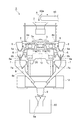
図1に示されるように、組合せ計量装置1は、投入シュート2と、分散フィーダ3と、複数の放射フィーダ(搬送部)4と、複数のプールホッパ5と、複数の計量ホッパ(ホッパ)6と、複数のブースタホッパ(ホッパ)7と、集合シュート8と、タイミングホッパ9と、計量部11と、制御部20と、を備える。組合せ計量装置1は、搬送コンベア50によって供給される物品を目標計量値となるように計量して製袋包装機60に供給する。ここで、物品は、農産物、水産物、加工食品等のように、単体質量にばらつきのある物品である。   As shown in FIG. 1, the combination weighing device 1 includes an input chute 2, a dispersion feeder 3, a plurality of radial feeders (conveying units) 4, a plurality of pool hoppers 5, and a plurality of weighing hoppers (hoppers) 6. A plurality of booster hoppers (hoppers) 7, a collective chute 8, a timing hopper 9, a weighing unit 11, and a control unit 20. The combination weighing device 1 measures the articles supplied by the conveyor 50 so as to have a target measurement value, and supplies them to the bag making and packaging machine 60. Here, the articles are articles such as agricultural products, marine products, processed foods, and the like that vary in unit mass.

上記における製袋包装機60は、フィルムを所定容量の袋に成形しつつ、組合せ計量装置1によって計量されて供給された物品を袋詰めする。なお、上記において物品は、単体質量にばらつきのない物品であっても構わない。   The bag making and packaging machine 60 described above packs the articles measured and supplied by the combination weighing device 1 while forming the film into a bag having a predetermined capacity. In the above, the article may be an article having no variation in the single mass.

投入シュート2は、搬送コンベア50の搬送端50aの下方に配置される。投入シュート2は、搬送コンベア50の搬送端50aから落下した物品を受けて下方に排出する。   The input chute 2 is disposed below the transport end 50 a of the transport conveyor 50. The input chute 2 receives articles dropped from the transport end 50a of the transport conveyor 50 and discharges them downward.

分散フィーダ3は、投入シュート2の下方に配置される。分散フィーダ3は、下方に向かって末広がりの円錐状の搬送面3aを有する。分散フィーダ3は、搬送面3aを振動させることで、投入シュート2から搬送面3aの頂部に排出された物品を搬送面3aの外縁に向かって均一に搬送する。   The dispersion feeder 3 is disposed below the charging chute 2. The dispersion feeder 3 has a conical conveying surface 3a that spreads downward toward the bottom. The dispersion feeder 3 vibrates the conveyance surface 3a to uniformly convey the articles discharged from the input chute 2 to the top of the conveyance surface 3a toward the outer edge of the conveyance surface 3a.

複数の放射フィーダ4は、分散フィーダ3の搬送面3aの外縁に沿って放射状に配置される。各放射フィーダ4は、搬送面3aの外縁の下方から外側に延在するトラフ4aを有する。各放射フィーダ4は、トラフ4aを振動させることで、搬送面3aの外縁から排出された物品をトラフ4aの先端部に向かって搬送する。   The plurality of radial feeders 4 are arranged radially along the outer edge of the conveying surface 3 a of the dispersion feeder 3. Each radiating feeder 4 has a trough 4a extending outward from below the outer edge of the transport surface 3a. Each radiation feeder 4 vibrates the trough 4a, and conveys the articles discharged from the outer edge of the conveying surface 3a toward the tip of the trough 4a.

各プールホッパ5は、各放射フィーダ4のトラフ4aの先端部の下方に配置される。各プールホッパ5は、その底部に対して、開閉可能なゲート5aを有する。各プールホッパ5は、ゲート5aを閉じることにより、対応するトラフ4aの先端部から排出された物品を一時的に貯留する。更に、各プールホッパ5は、ゲート5aを開くことで、一時的に貯留した物品を下方に排出する。   Each pool hopper 5 is disposed below the tip of the trough 4a of each radiation feeder 4. Each pool hopper 5 has a gate 5a that can be opened and closed with respect to its bottom. Each pool hopper 5 temporarily stores articles discharged from the tip of the corresponding trough 4a by closing the gate 5a. Further, each pool hopper 5 opens the gate 5a to discharge the temporarily stored articles downward.

各計量ホッパ6は、各プールホッパ5のゲート5aの下方に配置される。各計量ホッパ6は、その底部に対して、開閉可能なゲート6a及びゲート6bを有する。各計量ホッパ6は、ゲート6a及びゲート6bを閉じることにより、対応するプールホッパ5から排出された物品を一時的に貯留する。更に、各計量ホッパ6は、ゲート6a又はゲート6bを開くことで、一時的に貯留した物品を下方に排出する。   Each weighing hopper 6 is disposed below the gate 5 a of each pool hopper 5. Each weighing hopper 6 has a gate 6a and a gate 6b that can be opened and closed with respect to the bottom thereof. Each weighing hopper 6 temporarily stores articles discharged from the corresponding pool hopper 5 by closing the gate 6a and the gate 6b. Furthermore, each weighing hopper 6 discharges the temporarily stored articles downward by opening the gate 6a or the gate 6b.

各ブースタホッパ7は、各計量ホッパ6のゲート6aの下方に配置される。各ブースタホッパ7は、その底部に対して、開閉可能なゲート7aを有する。各ブースタホッパ7は、ゲート7aを閉じることにより、対応する計量ホッパ6のゲート6a側から排出された物品を一時的に貯留する。更に、各ブースタホッパ7は、ゲート7aを開くことで、一時的に貯留した物品を下方に排出する。   Each booster hopper 7 is disposed below the gate 6 a of each weighing hopper 6. Each booster hopper 7 has a gate 7a that can be opened and closed with respect to its bottom. Each booster hopper 7 temporarily stores the articles discharged from the gate 6a side of the corresponding weighing hopper 6 by closing the gate 7a. Furthermore, each booster hopper 7 discharges the temporarily stored articles downward by opening the gate 7a.

集合シュート8は、下方に向かって先細りの円錐台の内面8aを有する筒状構造を有する。集合シュート8は、内面8aが全ての計量ホッパ6及び全てのブースタホッパ7の下方に位置するように配置される。集合シュート8は、各計量ホッパ6のゲート6b側から排出された物品、及び各ブースタホッパ7から排出された物品を内面8aで受けて下方に排出する。   The collective chute 8 has a cylindrical structure having an inner surface 8a of a truncated cone tapered downward. The collecting chute 8 is arranged so that the inner surface 8 a is positioned below all the weighing hoppers 6 and all the booster hoppers 7. The collecting chute 8 receives the articles discharged from the gate 6b side of each weighing hopper 6 and the articles discharged from each booster hopper 7 by the inner surface 8a and discharges them downward.

タイミングホッパ9は、集合シュート8の下方に配置される。タイミングホッパ9は、その底部に対して、開閉可能なゲート9aを有する。タイミングホッパ9は、ゲート9aを閉じることにより、集合シュート8から排出された物品を一時的に貯留する。更に、タイミングホッパ9は、ゲート9aを開くことで、一時的に貯留した物品を製袋包装機60に排出する。   The timing hopper 9 is disposed below the collective chute 8. The timing hopper 9 has a gate 9a that can be opened and closed with respect to its bottom. The timing hopper 9 temporarily stores the articles discharged from the collective chute 8 by closing the gate 9a. Further, the timing hopper 9 opens the gate 9 a to discharge the temporarily stored article to the bag making and packaging machine 60.

計量部11は、フレーム12に支持されたケース13内に配置される。計量部11は、複数のロードセル11aを有する。各ロードセル11aは、対応する計量ホッパ6を支持する。計量部11は、各計量ホッパ6に物品が一時的に貯留される際に、当該物品の質量に応じた計量値を計量する。   The measuring unit 11 is disposed in a case 13 supported by the frame 12. The weighing unit 11 has a plurality of load cells 11a. Each load cell 11a supports a corresponding weighing hopper 6. When the article is temporarily stored in each weighing hopper 6, the weighing unit 11 measures a measurement value corresponding to the mass of the article.

制御部20は、ケース13内に配置される。制御部20は、組合せ計量装置1における各種動作を制御する機器であり、CPU(Central Processing Unit)、ROM(Read Only Memory)、RAM(Random Access Memory)等を備える。制御部20は、分散フィーダ3及び各放射フィーダ4の搬送動作、各プールホッパ5のゲート5aの開閉動作、各計量ホッパ6のゲート6a及びゲート6bの開閉動作、各ブースタホッパ7のゲート7a開閉動作、並びに各タイミングホッパ9のゲート9a等、組合せ計量装置1の各部の動作を制御する。   The control unit 20 is disposed in the case 13. The control unit 20 is a device that controls various operations in the combination weighing device 1, and includes a CPU (Central Processing Unit), a ROM (Read Only Memory), a RAM (Random Access Memory), and the like. The control unit 20 performs the transport operation of the dispersion feeder 3 and each radiation feeder 4, the opening / closing operation of the gate 5a of each pool hopper 5, the opening / closing operation of the gate 6a and gate 6b of each weighing hopper 6, and the gate 7a opening / closing of each booster hopper 7. The operation and the operation of each part of the combination weighing device 1 such as the gate 9a of each timing hopper 9 are controlled.

制御部20は、計量部11によって計量された計量値と、当該計量値に対応する物品が貯留される計量ホッパ6及び/又はブースタホッパ7とを対応付けて記憶する。具体的には、制御部20は、計量部11によって計量された物品が計量ホッパ6に貯留される場合、計量部11によって計量された計量値と、当該計量値に対応する物品を貯留する計量ホッパ6とを対応付けて記憶する。計量部11によって計量された物品が当該計量ホッパ6に対応するブースタホッパ7に排出された場合、制御部20は、計量部11によって計量された物品の計量値と、当該計量ホッパ6に対応するブースタホッパ7とを対応付けて記憶する。   The control unit 20 stores the measurement value measured by the measurement unit 11 in association with the measurement hopper 6 and / or the booster hopper 7 in which articles corresponding to the measurement value are stored. Specifically, when the article weighed by the weighing unit 11 is stored in the weighing hopper 6, the control unit 20 stores the measured value measured by the measuring unit 11 and the article corresponding to the measured value. The hopper 6 is associated and stored. When the article weighed by the weighing unit 11 is discharged to the booster hopper 7 corresponding to the weighing hopper 6, the control unit 20 corresponds to the weighing value of the article weighed by the weighing unit 11 and the weighing hopper 6. The booster hopper 7 is stored in association with it.

制御部20は、計量部11によって計量され且つ複数の計量ホッパ6及び/又はブースタホッパ7にそれぞれ対応付けられた複数の計量値から、合計値が目標計量値となるように計量値の組合せを選択する。具体的には、制御部20は、計量部11によって出力された複数の計量値から、目標計量値を下限値とする所定範囲内に合計値が収まるように計量値の組合せを選択する。そして、制御部20は、当該組合せに対応する計量ホッパ6及び/又はブースタホッパ7に物品を排出させる。   The control unit 20 combines the measurement values so that the total value becomes the target measurement value from the plurality of measurement values measured by the measurement unit 11 and respectively associated with the plurality of measurement hoppers 6 and / or the booster hopper 7. select. Specifically, the control unit 20 selects a combination of measurement values from a plurality of measurement values output by the measurement unit 11 so that the total value falls within a predetermined range with the target measurement value as a lower limit value. Then, the control unit 20 causes the weighing hopper 6 and / or the booster hopper 7 corresponding to the combination to discharge the article.

なお、投入シュート2、分散フィーダ3、複数の放射フィーダ4、複数のプールホッパ5及び複数の計量ホッパ6は、ケース13に直接的に又は間接的に支持される。複数のブースタホッパ7、集合シュート8及びタイミングホッパ9は、フレーム12に直接的に又は間接的に支持される。   The charging chute 2, the dispersion feeder 3, the plurality of radiation feeders 4, the plurality of pool hoppers 5, and the plurality of weighing hoppers 6 are directly or indirectly supported by the case 13. The plurality of booster hoppers 7, the collective chute 8, and the timing hopper 9 are supported directly or indirectly by the frame 12.

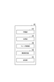
続いて、制御部20についてより詳細に説明する。図2は、制御部の機能的な構成を示す図である。図2に示されるように、制御部20は、記憶部22と、取得部24と、フィーダ制御部26と、異常特定部28と、設定部30と、を備える。制御部20は、記憶部22、取得部24、フィーダ制御部26及び異常特定部28を、各種制御処理を実行する概念的な部分として有する。このような概念的な部分は、例えばROMに格納されるプログラムがRAM上にロードされてCPUで実行されるソフトウェアとして構成できる。   Next, the control unit 20 will be described in more detail. FIG. 2 is a diagram illustrating a functional configuration of the control unit. As shown in FIG. 2, the control unit 20 includes a storage unit 22, an acquisition unit 24, a feeder control unit 26, an abnormality specifying unit 28, and a setting unit 30. The control part 20 has the memory | storage part 22, the acquisition part 24, the feeder control part 26, and the abnormality specific part 28 as a conceptual part which performs various control processes. Such a conceptual part can be configured, for example, as software executed by the CPU after a program stored in the ROM is loaded onto the RAM.

記憶部22は、放射フィーダ4上における物品の層厚Sと、放射フィーダ4から対応する計量ホッパ6(プールホッパ5)への供給量W1と、放射フィーダ4の送力Pと、を記憶する。ここで、対応する層厚S、供給量W1及び送力Pは、下記の式(1)を満たすものとする。図4に示されるように、層厚Sが厚いほど、プールホッパ5(計量ホッパ6)に供給される供給量W1が多くなる傾向がある。
P=A×W/S+B …(1)
The storage unit 22 stores the article layer thickness S on the radiation feeder 4, the supply amount W1 from the radiation feeder 4 to the corresponding weighing hopper 6 (pool hopper 5), and the feeding force P of the radiation feeder 4. . Here, the corresponding layer thickness S, supply amount W1, and feed force P satisfy the following formula (1). As shown in FIG. 4, as the layer thickness S increases, the supply amount W1 supplied to the pool hopper 5 (the weighing hopper 6) tends to increase.
P = A × W / S + B (1)

送力Pは、放射フィーダ4の振動の振幅である。送力Pの値が小さい場合には、振幅は、小さくなる。そのため、放射フィーダ4から計量ホッパ6(プールホッパ5)に供給される物品の供給量は少なくなる。送力Pの値が大きい場合には、振幅は大きくなる。そのため、放射フィーダ4から計量ホッパ6に供給される物品の供給量は多くなる。   The feeding force P is the amplitude of vibration of the radiation feeder 4. When the value of the feeding force P is small, the amplitude is small. Therefore, the supply amount of articles supplied from the radiation feeder 4 to the weighing hopper 6 (pool hopper 5) is reduced. When the value of the feeding force P is large, the amplitude becomes large. Therefore, the supply amount of articles supplied from the radiation feeder 4 to the weighing hopper 6 increases.

層厚Sは、図3に示されるように、放射フィーダ4の排出端近傍における、放射フィーダ4の底面4sと物品の上部との間の距離である。層厚Sは、測距センサ32によって検知される。測距センサ32は、各放射フィーダ4の上方に、各放射フィーダ4に対応して配置される。測距センサ32は、支持フレーム(図示しない)に取り付けられ、放射フィーダ4の上方に位置する。   As shown in FIG. 3, the layer thickness S is a distance between the bottom surface 4 s of the radiation feeder 4 and the upper part of the article in the vicinity of the discharge end of the radiation feeder 4. The layer thickness S is detected by the distance measuring sensor 32. The distance measuring sensor 32 is disposed above each radiation feeder 4 so as to correspond to each radiation feeder 4. The distance measuring sensor 32 is attached to a support frame (not shown) and is located above the radiation feeder 4.

なお、上記においては組合せ計量装置1が層厚Sを検知する測距センサ32を有する構成を説明した。しかし、この測距センサ32は、組合せ計量装置1とは異なる外部装置として構成されても構わない。この場合、組合せ計量装置1は、この外部装置から、単に層厚Sに関する情報を取得する。要するに、測距センサ32は必須構成ではなく、結果として、組合せ計量装置1が層厚Sに関する情報を取得する構成であればどのようなものでも構わない。   In the above description, the configuration in which the combination weighing device 1 includes the distance measuring sensor 32 that detects the layer thickness S has been described. However, the distance measuring sensor 32 may be configured as an external device different from the combination weighing device 1. In this case, the combination weighing device 1 simply acquires information on the layer thickness S from the external device. In short, the distance measuring sensor 32 is not an essential configuration, and as a result, any configuration may be used as long as the combination weighing device 1 acquires information on the layer thickness S.

測距センサ32は、当該測距センサ32と放射フィーダ4上の物品との間の距離を検出する。測距センサ32は、例えば、物品に向かって光を照射し、物品で反射された光を受光する。これにより、測距センサ32は、測距センサ32と物品との間の距離を得る。図3に示されるように、測距センサ32は、放射フィーダ4の排出端近傍に位置する物品との間の距離を検出する。排出端近傍とは、放射フィーダ4の搬送方向の先端から所定距離だけ後退する位置である。例えば、この位置は、放射フィーダ4の先端から30mm〜50mm程度後退した位置である。測距センサ32は、検出した物品との距離を示す検出信号を取得部24及びフィーダ制御部26に送信する。   The distance measuring sensor 32 detects the distance between the distance measuring sensor 32 and the article on the radiation feeder 4. For example, the distance measuring sensor 32 emits light toward the article and receives the light reflected by the article. Thereby, the distance measuring sensor 32 obtains the distance between the distance measuring sensor 32 and the article. As shown in FIG. 3, the distance measuring sensor 32 detects a distance from an article located near the discharge end of the radiation feeder 4. The vicinity of the discharge end is a position where the radiation feeder 4 moves backward by a predetermined distance from the tip in the transport direction. For example, this position is a position retracted about 30 mm to 50 mm from the tip of the radiation feeder 4. The distance measuring sensor 32 transmits a detection signal indicating the detected distance to the article to the acquisition unit 24 and the feeder control unit 26.

上記式(1)において、「A」及び「B」のそれぞれは、係数である。係数A及び係数Bは、物品の層厚S及び供給量W1に基づいて求められる値と送力Pとの関係を紐づけるパラメータである。係数A及び係数Bは、組合せ計量装置1の初期状態においては、例えば、組合せ計量装置1の構成に応じて、経験的に求められた値が初期値として与えられている。各係数A及び係数Bは、放射フィーダ4の形状及び/又は物品の種類に応じて変更可能な値である。   In the above formula (1), each of “A” and “B” is a coefficient. The coefficient A and the coefficient B are parameters that link the relationship between the value obtained based on the layer thickness S of the article and the supply amount W1 and the feed force P. As for the coefficient A and the coefficient B, in the initial state of the combination weighing device 1, for example, values obtained empirically according to the configuration of the combination weighing device 1 are given as initial values. Each coefficient A and coefficient B are values that can be changed according to the shape of the radiation feeder 4 and / or the type of article.

取得部24は、過去から継続的に取得した層厚S、供給量W1及び送力Pに基づき、上記係数A及び係数Bを逐次算出する。つまり、取得部24は、係数A及び係数Bを学習制御により算出する。   The acquisition unit 24 sequentially calculates the coefficient A and the coefficient B based on the layer thickness S, the supply amount W1, and the feeding force P acquired continuously from the past. That is, the acquisition unit 24 calculates the coefficient A and the coefficient B by learning control.

具体的には、取得部24は、予め設定された目標供給量Wとなるように層厚Sに応じて、放射フィーダ4を送力Pにて動作時間だけ動作させた際の、実際の供給量W1を履歴情報として記憶する。この場合、取得部24は、測距センサ32から送信された検出信号が示す距離に基づいて、物品の層厚Sを算出する。詳細には、取得部24は、放射フィーダ4の底面4sから測距センサ32までの距離と、検出信号が示す距離との差に基づいて、物品の層厚Sを算出する。取得部24は、送力Pと、供給量W1を層厚Sによって除した値(供給量W1/層厚S)と、動作時間とを関連付けて記憶部22に記憶させる。   Specifically, the acquisition unit 24 performs the actual supply when the radiation feeder 4 is operated with the power P for the operation time in accordance with the layer thickness S so that the target supply amount W is set in advance. The amount W1 is stored as history information. In this case, the acquisition unit 24 calculates the layer thickness S of the article based on the distance indicated by the detection signal transmitted from the distance measuring sensor 32. Specifically, the acquisition unit 24 calculates the layer thickness S of the article based on the difference between the distance from the bottom surface 4s of the radiation feeder 4 to the distance measuring sensor 32 and the distance indicated by the detection signal. The acquisition unit 24 stores the power P, the value obtained by dividing the supply amount W1 by the layer thickness S (supply amount W1 / layer thickness S), and the operation time in the storage unit 22 in association with each other.

取得部24は、このように記憶させた複数の履歴情報に基づき、係数A及び係数Bを算出する。この場合、取得部24は、層厚S、供給量W1及び送力Pに対して上記式(1)に示す関係が成立すると仮定して係数A及び係数Bを算出する。具体的に取得部24は、新たな係数A及び係数Bを、例えば、動作時間毎に、これまでに取得した履歴情報に基づき最小二乗法等により導出する。また、新たな係数A及び係数Bを導出する際には、個々の履歴情報に重み(新たな係数A及び係数Bを決定する際の影響力の大きさ)を設定できる。例えば、現在の時刻に対して近い情報については、その重みは高くなる。   The acquisition unit 24 calculates the coefficient A and the coefficient B based on the plurality of history information stored in this way. In this case, the acquisition unit 24 calculates the coefficient A and the coefficient B on the assumption that the relationship shown in the above formula (1) is established with respect to the layer thickness S, the supply amount W1, and the feeding force P. Specifically, the acquisition unit 24 derives a new coefficient A and coefficient B by, for example, the least square method based on the history information acquired so far for each operation time. In addition, when deriving new coefficients A and B, weights (magnitude of influence when determining new coefficients A and B) can be set for individual history information. For example, for information close to the current time, the weight is high.

取得部24は、履歴情報が更新されたタイミングで、新たな係数A及び係数Bを算出しても構わない。この係数A及び係数Bは、現在又は将来における送力Pを決定する際に利用される。   The acquisition unit 24 may calculate new coefficients A and B at the timing when the history information is updated. The coefficient A and the coefficient B are used when determining the current or future power P.

フィーダ制御部26は、放射フィーダ4の送力Pを制御する。フィーダ制御部26は、上記式(1)を用いて、測距センサ32により検出された距離に基づく物品の層厚Sと、設定された目標供給量となる供給量W1と、から得られる送力Pにて放射フィーダ4を制御する。フィーダ制御部26は、物品の層厚Sと、目標供給量となる供給量W1とを上記式(1)に代入し、送力Pを算出する。フィーダ制御部26は、算出した送力Pにより、連続的に動作する放射フィーダ4の動作を制御する。   The feeder control unit 26 controls the feeding force P of the radiation feeder 4. Using the above equation (1), the feeder control unit 26 uses the above-described equation (1) to obtain the article thickness S based on the distance detected by the distance measuring sensor 32 and the supply amount W1 that is the set target supply amount. The radiation feeder 4 is controlled by the force P. The feeder control unit 26 calculates the feed force P by substituting the layer thickness S of the article and the supply amount W1 as the target supply amount into the above equation (1). The feeder control unit 26 controls the operation of the radiation feeder 4 that operates continuously by the calculated feed force P.

異常特定部28は、異常が発生している放射フィーダ4を特定する。ここで、各放射フィーダ4それぞれにおいて算出される係数A及び係数Bは、理想的には、学習による更新の蓄積によってほぼ同様の値となる。別の観点で説明すると、放射フィーダ4それぞれに設定される目標供給量が異なる場合であっても、係数A及び係数Bは、上記のように、ほぼ同様の値となる。この異常特定部28は、この性質を利用して、放射フィーダ4毎の係数A及び係数Bを比較し、複数の放射フィーダ4のうち異常が発生している放射フィーダ4を特定する。異常は、例えば、放射フィーダ4において何らかの不具合によって物品の搬送が滞り、係数A及び係数Bが異常値となることである。また、別の具体例として、異常は、一の放射フィーダ4の取付部分が緩んでいるため、他の放射フィーダ4における係数A及び係数Bと比較して、一の放射フィーダ4に係る係数A及び係数Bが異常値となることである。要するに、異常とは、放射フィーダ4自体に発生する不具合を意味する。   The abnormality specifying unit 28 specifies the radiation feeder 4 in which an abnormality has occurred. Here, the coefficient A and the coefficient B calculated in each of the radiation feeders 4 ideally have substantially the same value due to accumulation of updates by learning. If it demonstrates from another viewpoint, even if it is a case where the target supply amount set to each radiation feeder 4 differs, the coefficient A and the coefficient B will become a substantially the same value as mentioned above. Using this property, the abnormality identification unit 28 compares the coefficient A and the coefficient B for each radiation feeder 4 and identifies the radiation feeder 4 in which an abnormality has occurred among the plurality of radiation feeders 4. The abnormality is, for example, that the conveyance of the article is delayed due to some trouble in the radiation feeder 4, and the coefficient A and the coefficient B become abnormal values. Further, as another specific example, the abnormality is that the attachment portion of one radiation feeder 4 is loosened, so that the coefficient A related to one radiation feeder 4 is compared with the coefficient A and coefficient B in the other radiation feeder 4. And the coefficient B becomes an abnormal value. In short, the abnormality means a problem that occurs in the radiation feeder 4 itself.

上記における何らかの不具合とは、例えば、放射フィーダ4とその下方に設置される加震機との間における接続が正しく取り付けられていない場合がある。また、別の不具合としては、物品に付着した味材等が放射フィーダ4に付着し当該物品の搬送が妨げられる場合がある。   For example, there is a case where the connection between the radiation feeder 4 and the shaker installed therebelow is not properly attached. Further, as another problem, there is a case where a flavoring material or the like attached to the article adheres to the radiation feeder 4 and the conveyance of the article is hindered.

異常特定部28は、放射フィーダ4毎の係数A及び係数Bを比較し、一の放射フィーダ4の係数A及び係数Bが複数の他の放射フィーダ4の係数A及び係数Bの所定の範囲を超えている場合に、一の放射フィーダ4に異常が発生していると判断する。所定の範囲は、任意に設定されればよい。   The abnormality specifying unit 28 compares the coefficient A and the coefficient B for each radiation feeder 4, and the coefficient A and the coefficient B of one radiation feeder 4 are within a predetermined range of the coefficient A and the coefficient B of a plurality of other radiation feeders 4. If it exceeds, it is determined that an abnormality has occurred in one radiation feeder 4. The predetermined range may be set arbitrarily.

なお、異常特定部28は、上記の動作に限定されるものではなく、例えば、放射フィーダ4それぞれの係数A及び係数Bのうち少なくとも一部に基づいて、比較基準とする係数を設定しても構わない。この場合、異常特定部28は、設定した比較基準とする係数と、放射フィーダ4それぞれに対して設定される係数A及び係数Bを比較する。その結果、異常特定部28は、一の放射フィーダ4の係数A及び係数Bがこの比較基準とする係数と所定値乖離している場合、この放射フィーダ4に異常が発生していると判断する。   The abnormality specifying unit 28 is not limited to the above-described operation. For example, the abnormality specifying unit 28 may set a coefficient as a comparison reference based on at least a part of the coefficient A and the coefficient B of each of the radiation feeders 4. I do not care. In this case, the abnormality specifying unit 28 compares the set coefficient as the comparison reference with the coefficient A and the coefficient B set for each of the radiation feeders 4. As a result, the abnormality specifying unit 28 determines that an abnormality has occurred in the radiation feeder 4 when the coefficient A and the coefficient B of one radiation feeder 4 are different from the coefficient used as the comparison reference by a predetermined value. .

異常特定部28は、所定のタイミングで、各放射フィーダ4の係数A及び係数Bを比較する。本実施形態では、所定のタイミングは、例えば、組合せ計量が所定回数(例えば、100回)実施されたときである。このように組合せ計量が所定回数以上、実施された後に各放射フィーダ4の係数A及び係数Bを比較することで、その比較自体の精度を向上できる。   The abnormality specifying unit 28 compares the coefficient A and the coefficient B of each radiation feeder 4 at a predetermined timing. In the present embodiment, the predetermined timing is, for example, when combination weighing is performed a predetermined number of times (for example, 100 times). Thus, the accuracy of the comparison itself can be improved by comparing the coefficient A and the coefficient B of each radiation feeder 4 after the combination weighing is performed a predetermined number of times or more.

異常特定部28は、係数A及び係数Bの比較を行うタイミングにおいて、最新の同じタイミングの係数A及び係数Bを比較する。例えば、異常特定部28は、係数A及び係数Bの比較を行うタイミングにおいて、最新の係数A及び係数Bを記憶部22から読み出し、各放射フィーダ4の係数A及び係数Bを比較する。   The abnormality specifying unit 28 compares the latest coefficient A and coefficient B at the same timing at the timing when the coefficient A and the coefficient B are compared. For example, the abnormality specifying unit 28 reads the latest coefficient A and coefficient B from the storage unit 22 at the timing when the coefficient A and the coefficient B are compared, and compares the coefficient A and the coefficient B of each radiation feeder 4.

異常特定部28は、異常が発生している放射フィーダ4を特定すると、例えば、放射フィーダ4に異常が発生していることを報知する。具体的には、異常特定部28は、例えば、異常が発生している放射フィーダ4を特定すると、その旨を、設定及び管理を行うためのディスプレイに表示させる。報知手段としては、異常が発生している放射フィーダ4を識別できるものであれば特に限定されず、ランプ、ブザー等であってもよい。   When the abnormality specifying unit 28 specifies the radiation feeder 4 in which an abnormality has occurred, for example, the abnormality specifying unit 28 notifies the radiation feeder 4 that an abnormality has occurred. Specifically, for example, when specifying the radiation feeder 4 in which an abnormality has occurred, the abnormality specifying unit 28 displays that fact on a display for performing setting and management. The notification means is not particularly limited as long as it can identify the radiation feeder 4 in which an abnormality has occurred, and may be a lamp, a buzzer, or the like.

設定部30は、異常特定部28によって異常が発生している放射フィーダ4を特定すると、特定した放射フィーダ4に設定される係数A及び係数Bを、特定した放射フィーダ4とは異なる放射フィーダ4に設定される係数A及び係数Bに基づき算出される係数A及び係数Bに置き換える。具体的には、設定部30は、異常を特定した放射フィーダ4に隣接する放射フィーダ4に設定される係数A及び係数Bの平均値を、置き換えに係る係数A及び係数Bとして算出する。設定部30は、当該係数A及び係数Bを異常が特定された放射フィーダ4に設定する。これにより、放射フィーダ4は、再稼働したときに、当該係数A及び係数Bに基づく送力Pにより制御される。   When the setting unit 30 identifies the radiation feeder 4 in which an abnormality has occurred by the abnormality identifying unit 28, the coefficient A and the coefficient B set in the identified radiation feeder 4 are different from the radiation feeder 4 that has been identified. Is replaced with the coefficient A and the coefficient B calculated based on the coefficient A and the coefficient B set in (1). Specifically, the setting unit 30 calculates the average value of the coefficient A and the coefficient B set in the radiation feeder 4 adjacent to the radiation feeder 4 that has specified the abnormality as the coefficient A and the coefficient B related to replacement. The setting unit 30 sets the coefficient A and the coefficient B to the radiation feeder 4 in which the abnormality is specified. Thereby, the radiation feeder 4 is controlled by the feeding force P based on the coefficient A and the coefficient B when the radiation feeder 4 is restarted.

以上説明したように、本実施形態に係る組合せ計量装置1では、取得部24は、過去に設定された放射フィーダ4における物品の送力に関する設定値と、設定値が設定されていた際に放射フィーダ4から計量ホッパ6(プールホッパ5)に供給された物品の供給量と、を関連づけた複数の履歴情報に基づき決定されるパラメータであって、放射フィーダ4の送力を決定する際に利用する係数A及び係数Bを、放射フィーダ4毎に取得する。異常特定部28は、放射フィーダ4毎の係数A及び係数Bを比較することにより、複数の放射フィーダ4のうち異常が発生している放射フィーダ4を特定する。このように、組合せ計量装置1では、計量値ではなく係数A及び係数Bの比較によって異常が発生している放射フィーダ4を特定するため、例えば、物品は正常に搬送されているが、異常が発生している放射フィーダ4を特定できる。なお、異常が発生している放射フィーダ4を特定するとは、実際に異常が発生している放射フィーダ4を特定すること、及び、異常が発生していると予測される放射フィーダ4を特定することを含み得る。   As described above, in the combination weighing device 1 according to the present embodiment, the acquisition unit 24 radiates when the set value related to the power of the article in the radiating feeder 4 set in the past and the set value are set. A parameter determined based on a plurality of pieces of history information in association with the supply amount of articles supplied from the feeder 4 to the weighing hopper 6 (pool hopper 5), and is used when determining the feed force of the radiation feeder 4 The coefficient A and the coefficient B to be acquired are acquired for each radiation feeder 4. The abnormality identifying unit 28 identifies the radiation feeder 4 in which an abnormality has occurred among the plurality of radiation feeders 4 by comparing the coefficient A and the coefficient B for each radiation feeder 4. Thus, in the combination weighing device 1, in order to identify the radiation feeder 4 in which an abnormality has occurred by comparing the coefficient A and the coefficient B instead of the measurement value, for example, the article is normally conveyed, but the abnormality is The generated radiation feeder 4 can be identified. Note that specifying the radiation feeder 4 in which an abnormality has occurred specifies the radiation feeder 4 in which an abnormality has actually occurred, and specifies the radiation feeder 4 that is predicted to have an abnormality. Can include.

本実施形態では、放射フィーダ4上の物品の層厚Sを検知する測距センサ32を備える。取得部24は、放射フィーダ4上の物品の層厚S及び供給量W1に基づいて求められる値と送力Pに関する設定値との関係を紐づけるパラメータを取得する。この構成では、放射フィーダ4上の物品の層厚Sの変化により、係数A及び係数Bが変化する。そのため、例えば、放射フィーダ4上の物品に異常が生じている場合には、係数A及び係数Bにその異常の状況が反映される。したがって、組合せ計量装置1では、放射フィーダ4に異常が発生していることをより確実に特定できる。   In the present embodiment, a distance measuring sensor 32 that detects the layer thickness S of the article on the radiation feeder 4 is provided. The acquisition unit 24 acquires a parameter that associates a relationship between a value obtained based on the layer thickness S of the article on the radiation feeder 4 and the supply amount W1 and a set value related to the power supply P. In this configuration, the coefficient A and the coefficient B change due to the change in the layer thickness S of the article on the radiation feeder 4. Therefore, for example, when an abnormality occurs in the article on the radiating feeder 4, the abnormality state is reflected in the coefficient A and the coefficient B. Therefore, the combination weighing device 1 can more reliably specify that an abnormality has occurred in the radiation feeder 4.

本実施形態では、異常特定部28は、制御部は、取得部24において取得した最新の係数A及び係数Bを用いて、放射フィーダ4毎の係数A及び係数Bを比較する。これにより、組合せ計量装置1では、最新の状態における放射フィーダ4の異常を特定できる。   In the present embodiment, the abnormality specifying unit 28 uses the latest coefficient A and coefficient B acquired by the acquisition unit 24 to compare the coefficient A and the coefficient B for each radiation feeder 4. Thereby, in the combination weighing device 1, it is possible to specify the abnormality of the radiation feeder 4 in the latest state.

本実施形態では、異常特定部28は、取得部24によって同じタイミングに取得した放射フィーダ4毎の係数A及び係数Bを比較する。取得したタイミングが異なる場合、そのタイミング毎に物品等の状態(大きさ等)が異なることがあるため、係数A及び係数Bにもその状態が反映され得る。そのため、それぞれ異なるタイミングにおける係数A及び係数Bを用いた場合には、状態の違いが異常判定に影響することがある。組合せ計量装置1では、同じタイミングにおける係数A及び係数Bを比較するため、状態の違いが異常判定に影響しない。したがって、放射フィーダ4の異常をより適切に特定できる。   In the present embodiment, the abnormality specifying unit 28 compares the coefficient A and the coefficient B for each radiation feeder 4 acquired at the same timing by the acquiring unit 24. If the acquired timing is different, the state (size, etc.) of the article may be different at each timing, and the state can be reflected in the coefficient A and the coefficient B. For this reason, when the coefficient A and the coefficient B at different timings are used, the difference in state may affect the abnormality determination. Since the combination weighing device 1 compares the coefficient A and the coefficient B at the same timing, the difference in the state does not affect the abnormality determination. Therefore, the abnormality of the radiation feeder 4 can be specified more appropriately.

本実施形態では、異常特定部28は、組合せ計量が所定回数実行されたときに、放射フィーダ4毎の係数A及び係数Bを比較してもよい。これにより、組合せ計量装置1では、定期的に放射フィーダ4毎の係数A及び係数Bを比較するため、放射フィーダ4の異常を定期的に確認できる。   In the present embodiment, the abnormality specifying unit 28 may compare the coefficient A and the coefficient B for each radiation feeder 4 when the combination weighing is executed a predetermined number of times. Thereby, in combination weighing device 1, since coefficient A and coefficient B for every radiation feeder 4 are compared periodically, abnormality of radiation feeder 4 can be checked regularly.

本実施形態では、設定部30は、複数の放射フィーダ4から異常が発生している放射フィーダ4を特定した場合、特定した放射フィーダ4に設定される係数A及び係数Bを、特定した放射フィーダ4とは異なる放射フィーダ4に設定される係数A及び係数Bに基づき算出される係数A及び係数Bに置き換える。これにより、異常が特定された放射フィーダ4が再稼働するときに、当該放射フィーダ4に適した係数A及び係数Bで放射フィーダ4を稼働させることができる。   In the present embodiment, when the setting unit 30 identifies a radiation feeder 4 in which an abnormality has occurred from a plurality of radiation feeders 4, the setting unit 30 identifies the specified radiation feeder 4 with the coefficient A and the coefficient B set in the identified radiation feeder 4. 4 is replaced with a coefficient A and a coefficient B calculated based on a coefficient A and a coefficient B set in the radiation feeder 4 different from 4. Thereby, when the radiation feeder 4 in which abnormality is specified is restarted, the radiation feeder 4 can be operated with the coefficient A and the coefficient B suitable for the radiation feeder 4.

本実施形態では、設定部30は、異常を特定した放射フィーダ4に隣接する放射フィーダ4に設定される係数A及び係数Bの平均値を、置き換えに係る係数A及び係数Bとして算出する。異常が特定された放射フィーダ4に隣接する放射フィーダ4の搬送状況は、異常が特定された放射フィーダ4の搬送状況と類似している。そのため、異常が特定された放射フィーダ4に隣接する放射フィーダ4に設定される係数A及び係数Bの平均値を置き換えに係る係数A及び係数Bとすることにより、異常が特定された放射フィーダ4を、当該放射フィーダ4の状況に最適な係数A及び係数Bで再稼働させることができる。   In the present embodiment, the setting unit 30 calculates the average value of the coefficient A and the coefficient B set in the radiation feeder 4 adjacent to the radiation feeder 4 that has specified the abnormality as the coefficient A and the coefficient B related to replacement. The conveyance situation of the radiation feeder 4 adjacent to the radiation feeder 4 in which the abnormality is specified is similar to the conveyance situation of the radiation feeder 4 in which the abnormality is specified. For this reason, the radiation feeder 4 in which an abnormality is specified is obtained by setting the average value of the coefficient A and the coefficient B set in the radiation feeder 4 adjacent to the radiation feeder 4 in which the abnormality is specified as the coefficient A and the coefficient B related to replacement. Can be restarted with a coefficient A and a coefficient B that are optimal for the situation of the radiation feeder 4.

以上、本発明の一実施形態について説明したが、本発明は、上記実施形態に限定されるものではない。例えば、本発明の搬送部は、上述した分散フィーダ3及び複数の放射フィーダ4に限定されず、物品を搬送することができる構成を有するものであればよい。また、本発明の複数のホッパは、上述した複数の計量ホッパ6及び複数のブースタホッパ7のように環状に配置されたものに限定されず、マトリックス状に配置されたものであってもよい。また、本発明の組合せ計量装置は、複数のブースタホッパ7を備えていなくてもよい。   Although one embodiment of the present invention has been described above, the present invention is not limited to the above embodiment. For example, the conveyance part of this invention is not limited to the dispersion | distribution feeder 3 and several radiation feeder 4 which were mentioned above, What is necessary is just to have a structure which can convey articles | goods. Further, the plurality of hoppers of the present invention are not limited to those arranged in an annular shape like the plurality of weighing hoppers 6 and the plurality of booster hoppers 7 described above, and may be arranged in a matrix. Further, the combination weighing device of the present invention may not include a plurality of booster hoppers 7.

上記実施形態では、異常特定部28が、組合せ計量が所定回数実施されたときに、各放射フィーダ4の動作を制御する係数A及び係数Bを比較する形態を一例に説明した。しかし、異常特定部28が係数A及び係数Bを比較するタイミングは、これに限定されない。異常特定部28は、所定時間毎に、係数A及び係数Bを比較してもよい。また、所定時間は、毎回異なっていてもよい。   In the above embodiment, an example has been described in which the abnormality specifying unit 28 compares the coefficient A and the coefficient B that control the operation of each radiation feeder 4 when the combination weighing is performed a predetermined number of times. However, the timing at which the abnormality specifying unit 28 compares the coefficient A and the coefficient B is not limited to this. The abnormality specifying unit 28 may compare the coefficient A and the coefficient B every predetermined time. Further, the predetermined time may be different every time.

上記実施形態では、異常特定部28が、係数A及び係数Bの比較を行うタイミングにおいて、最新の同じタイミングの係数A及び係数Bを比較する形態を一例に説明した。しかし、異常特定部28は、任意のタイミングの係数A及び係数Bを比較してもよい。   In the above-described embodiment, an example has been described in which the abnormality specifying unit 28 compares the latest coefficient A and coefficient B at the same timing at the timing when the coefficient A and the coefficient B are compared. However, the abnormality specifying unit 28 may compare the coefficient A and the coefficient B at any timing.

上記実施形態では、複数の放射フィーダ4から異常が発生している放射フィーダ4を特定した場合、設定部30が、特定した放射フィーダ4に設定される係数A及び係数Bを、特定した放射フィーダ4とは異なる放射フィーダ4に設定される係数A及び係数Bに基づき算出される係数A及び係数Bに置き換える形態を一例に説明した。しかし、設定部30は、複数の放射フィーダ4から異常が発生している放射フィーダ4を特定した場合、特定した放射フィーダ4に設定される係数A及び係数Bを初期化してもよい(初期値に戻してもよい)。これにより、異常が特定された放射フィーダ4が再稼働するときに、初期化された係数A及び係数Bで稼働させることができる。   In the above-described embodiment, when the radiation feeder 4 in which an abnormality has occurred is specified from the plurality of radiation feeders 4, the setting unit 30 specifies the coefficient A and the coefficient B set in the specified radiation feeder 4 and specifies the radiation feeder. The embodiment in which the coefficient A and the coefficient B calculated based on the coefficient A and the coefficient B set in the radiation feeder 4 different from 4 is replaced with an example has been described. However, when specifying the radiation feeder 4 in which an abnormality has occurred from the plurality of radiation feeders 4, the setting unit 30 may initialize the coefficient A and the coefficient B set in the identified radiation feeder 4 (initial value). You may return to Thereby, when the radiation feeder 4 in which the abnormality is specified is restarted, it can be operated with the initialized coefficient A and coefficient B.

上記実施形態では、制御部20が取得部24、異常特定部28及び設定部30を有する形態を一例に説明したが、取得部24、異常特定部28及び設定部30は、制御部20とは別に設けられてもよい。   In the above embodiment, the control unit 20 has been described as an example in which the control unit 20 includes the acquisition unit 24, the abnormality specifying unit 28, and the setting unit 30, but the acquisition unit 24, the abnormality specifying unit 28, and the setting unit 30 are the same as the control unit 20. It may be provided separately.

検知部として測距センサ32を一例に説明したが、検知部は測距センサ32に限定されない。検知部は、例えば、カメラ等であってもよい。   Although the distance measurement sensor 32 has been described as an example of the detection unit, the detection unit is not limited to the distance measurement sensor 32. The detection unit may be a camera or the like, for example.

上記実施形態では、測距センサ32が各放射フィーダ4に対応して1個ずつ設けられている形態を一例に説明したが、測距センサ32は、放射フィーダ4の搬送方向に沿って複数設けられていてもよい。これにより、複数箇所の物品の層厚を検知できる。そのため、放射フィーダ4にて搬送される物品の全体的な状態に基づいて、放射フィーダ4を制御することができる。   In the above-described embodiment, an example in which one distance measuring sensor 32 is provided corresponding to each radiation feeder 4 has been described as an example. However, a plurality of distance measuring sensors 32 are provided along the conveyance direction of the radiation feeder 4. It may be done. Thereby, the layer thickness of the articles | goods of several places is detectable. Therefore, the radiation feeder 4 can be controlled based on the overall state of the article conveyed by the radiation feeder 4.

上記実施形態では、測距センサ32が各放射フィーダ4に対応して1個ずつ設けられている形態を一例に説明したが、測距センサ32は、各放射フィーダ4に対応して設けられていなくてもよい。例えば、測距センサ32は、放射状に配置された放射フィーダ4に対して、例えば、2個ずつ間隔をあけて設けてもよい。分散フィーダ3から供給される物品の供給量は、隣接する放射フィーダ4において大幅に異ならないことがある。そこで、1つの測距センサ32により検出された結果を、その測距センサ32が検出した放射フィーダ4の両隣に配置された放射フィーダ4における物品との距離として用いる。この場合、測距センサ32(検知部)の数を減らすことができるため、コストの低減を図ることができる。   In the embodiment described above, an example in which one distance measuring sensor 32 is provided corresponding to each radiation feeder 4 has been described as an example. However, the distance measuring sensor 32 is provided corresponding to each radiation feeder 4. It does not have to be. For example, the distance measuring sensor 32 may be provided, for example, two by two with respect to the radiation feeders 4 arranged radially. The supply amount of articles supplied from the dispersion feeder 3 may not be significantly different between the adjacent radiating feeders 4. Therefore, the result detected by one distance measuring sensor 32 is used as the distance to the article in the radiation feeder 4 arranged on both sides of the radiation feeder 4 detected by the distance measuring sensor 32. In this case, since the number of distance measuring sensors 32 (detecting units) can be reduced, the cost can be reduced.

上記実施形態では、放射フィーダ4の送力Pが振幅である形態を一例に説明したが、送力Pは、放射フィーダ4の振動時間であってもよい。或いは、送力Pは、振幅及び振動時間の両方であってもよい。   In the above-described embodiment, the mode in which the feeding force P of the radiating feeder 4 has an amplitude has been described as an example, but the feeding force P may be the vibration time of the radiating feeder 4. Alternatively, the feeding force P may be both amplitude and vibration time.

上記実施形態では、測距センサ32により検出された検出信号に基づいて取得部24が物品の層厚Sを算出し、算出した層厚Sを用いて送力Pを求める形態を一例に説明したが、層厚Sを算出することなく送力Pを求める形態であってもよい。この構成の場合には、送力Pの算出に下記式(2)を用いる。
P=A1×W/(L−Sp)+B1 …(2)
In the above-described embodiment, an example has been described in which the acquisition unit 24 calculates the layer thickness S of the article based on the detection signal detected by the distance measuring sensor 32 and obtains the feeding force P using the calculated layer thickness S. However, the form which calculates | requires the feeding force P, without calculating the layer thickness S may be sufficient. In the case of this configuration, the following formula (2) is used to calculate the feeding force P.
P = A1 * W / (L-Sp) + B1 (2)

上記式(4)において、「A1」及び「B1」のそれぞれは、係数である。「L」は、放射フィーダ4の底面4sから測距センサ32までの距離である。「Sp」は、測距センサ32の検出信号が示す検出値(測距センサ32と物品との距離)である。取得部24は、測距センサ32から送信された検出信号を受け取ると、検出信号が示す検出値Spと、目標供給量となる供給量W1とを上記式(2)に代入し、送力Pを算出する。   In the above formula (4), each of “A1” and “B1” is a coefficient. “L” is the distance from the bottom surface 4 s of the radiation feeder 4 to the distance measuring sensor 32. “Sp” is a detection value (a distance between the distance measurement sensor 32 and the article) indicated by the detection signal of the distance measurement sensor 32. When the acquisition unit 24 receives the detection signal transmitted from the distance measuring sensor 32, the acquisition unit 24 substitutes the detection value Sp indicated by the detection signal and the supply amount W1 serving as the target supply amount into the above formula (2), and the transmission power P Is calculated.

上記実施形態では、測距センサ32により検出された検出信号に基づいて物品の層厚Sを算出しているが、物品の層厚は求めなくてもよい。この場合、係数A及び係数Bは、送力P及び供給量W1に基づいて算出される。   In the above embodiment, the layer thickness S of the article is calculated based on the detection signal detected by the distance measuring sensor 32, but the layer thickness of the article may not be obtained. In this case, the coefficient A and the coefficient B are calculated based on the feed force P and the supply amount W1.

上記実施形態に加えて、記憶部22には、供給量W1、係数A、及び、係数Bが、物品及び/又は放射フィーダ4の搬送路の形状に対応させて記憶されていてもよい。これにより、物品及び/又は放射フィーダ4の搬送路の形状に応じた制御ができる。そのため、物品及び/又は放射フィーダ4の搬送路の形状毎に、オペレータが係数等の設定を変更する手間を省くことができる。   In addition to the above embodiment, the storage unit 22 may store the supply amount W1, the coefficient A, and the coefficient B in association with the shape of the conveyance path of the article and / or the radiation feeder 4. Thereby, control according to the shape of the conveyance path of the article and / or the radiation feeder 4 can be performed. Therefore, it is possible to save the operator from changing the setting of the coefficient or the like for each shape of the conveyance path of the article and / or the radiation feeder 4.

上記実施形態では、搬送部として放射フィーダ4を一例に説明したが、搬送部は、例えば、回転駆動可能なコイルユニット(スクリュー)、又は、ベルトコンベアによって物品を搬送する形態であってもよい。コイルユニットの場合には、フィーダ制御部26は、送力として、コイルユニットの回転数(rpm)等を制御する。また、ベルトコンベアの場合には、フィーダ制御部26は、ベルトを駆動させるローラの回転数等を制御する。   In the above embodiment, the radiation feeder 4 has been described as an example of the transport unit. However, the transport unit may be configured to transport articles by a coil unit (screw) that can be rotationally driven or a belt conveyor, for example. In the case of a coil unit, the feeder control unit 26 controls the number of revolutions (rpm) of the coil unit and the like as a feeding force. In the case of a belt conveyor, the feeder controller 26 controls the number of rotations of a roller that drives the belt.

搬送部がコイルユニット又はベルトコンベアである場合、物品は、例えば鶏肉等のように、個々の質量が概ね同等のものである。このような物品の場合、係数A及び係数Bは、以下のように更新される。以下では、搬送部がコイルユニットの場合について説明する。   When a conveyance part is a coil unit or a belt conveyor, articles | goods are substantially equivalent in each mass like a chicken etc., for example. In the case of such an article, the coefficient A and the coefficient B are updated as follows. Below, the case where a conveyance part is a coil unit is demonstrated.

記憶部22は、コイルユニットから供給される物品の個数と、コイルユニットの回転数(送力)と、の関係を記憶する。物品の個数は、カメラにて撮像された画像に基づく画像処理により取得する。物品の単重が一定の場合には、計量部11により計量される物品の計量値に基づいて、物品の個数が取得されてもよい。取得部24は、学習によって上記係数A及び係数Bを更新する。具体的には、取得部24は、目標供給量となるように個数に応じて回転数を制御した際の、実際の供給量を履歴情報として記憶する。すなわち、取得部24は、回転数と個数とを関連付けて記憶部22に記憶させる。取得部24は、このような履歴情報に基づいて、係数A及び係数Bを算出する。   The storage unit 22 stores the relationship between the number of articles supplied from the coil unit and the number of rotations (feed force) of the coil unit. The number of articles is acquired by image processing based on an image captured by a camera. When the unit weight of the article is constant, the number of articles may be acquired based on the weighing value of the article weighed by the weighing unit 11. The acquisition unit 24 updates the coefficient A and the coefficient B by learning. Specifically, the acquisition unit 24 stores, as history information, the actual supply amount when the rotation speed is controlled according to the number so as to be the target supply amount. That is, the acquisition unit 24 stores the rotation number and the number in the storage unit 22 in association with each other. The acquisition unit 24 calculates the coefficient A and the coefficient B based on such history information.

上記実施形態では、組合せ計量装置1が分散フィーダ3を備え、放射フィーダ4が分散フィーダ3を中心に放射状に配置された円形配置の形態を一例に説明した。しかし、組合せ計量装置は、搬送部及び計量部のそれぞれが直線的に並んで配置された直線配置の形態であってもよい。   In the above-described embodiment, the combination weighing device 1 includes the dispersion feeder 3 and the radial feeder 4 is described as an example of a circular arrangement in which the dispersion feeder 3 is arranged radially around the dispersion feeder 3. However, the combination weighing device may be in the form of a linear arrangement in which each of the conveyance unit and the weighing unit is arranged linearly.

1…組合せ計量装置、4…放射フィーダ(搬送部)、6…計量ホッパ(ホッパ)、7…ブースタホッパ(ホッパ)、11…計量部、20…制御部、24…取得部、28…異常特定部(制御部)、30…設定部、32…測距センサ(検知部)。   DESCRIPTION OF SYMBOLS 1 ... Combination measuring device, 4 ... Radiation feeder (conveyance part), 6 ... Weighing hopper (hopper), 7 ... Booster hopper (hopper), 11 ... Weighing part, 20 ... Control part, 24 ... Acquisition part, 28 ... Abnormality identification Part (control part), 30 ... setting part, 32 ... distance measuring sensor (detection part).

Claims (9)

物品を搬送する複数の搬送部と、
複数の前記搬送部のそれぞれに対応して設けられ、前記搬送部によって搬送された前記物品を一時的に貯留する複数のホッパと、
前記ホッパのそれぞれに貯留された前記物品の質量に応じた計量値を出力する計量部と、
前記計量部によって出力された複数の前記計量値から、合計値が目標計量値となるように前記計量値の組合せを選択し、当該組合せに対応する前記ホッパに前記物品を排出させる制御部と、
過去に設定された前記搬送部における前記物品の送力に関する設定値と、前記設定値が設定されていた際に前記搬送部から前記ホッパに供給された前記物品の供給量と、を関連づけた複数の履歴情報に基づき決定されるパラメータであって、前記搬送部の送力を決定する際に利用するパラメータを、前記搬送部毎に取得する取得部と、を備え、
前記制御部は、前記搬送部毎の前記パラメータを比較し、複数の前記搬送部のうち異常が発生している前記搬送部を特定する、組合せ計量装置。
A plurality of conveyance units for conveying articles;
A plurality of hoppers provided corresponding to each of the plurality of transport units, and temporarily storing the article transported by the transport unit;
A weighing unit that outputs a weighing value according to the mass of the article stored in each of the hoppers;
A control unit that selects a combination of the measurement values from the plurality of measurement values output by the measurement unit so that a total value becomes a target measurement value, and causes the hopper corresponding to the combination to discharge the article;
A plurality of associations between a set value relating to the power of the article set in the transport unit set in the past and a supply amount of the article supplied from the transport unit to the hopper when the set value is set A parameter determined based on the history information, and an acquisition unit that acquires, for each transport unit, a parameter that is used when determining the feed force of the transport unit,
The control unit is a combination weighing device that compares the parameters for each of the conveyance units and identifies the conveyance unit in which an abnormality has occurred among the plurality of conveyance units.
前記取得部は、前記搬送部上の前記物品の高さに関する情報及び前記供給量に基づいて求められる値と前記送力に関する設定値との関係を紐づける前記パラメータを取得する、請求項1に記載の組合せ計量装置。   The acquisition unit acquires the parameter that associates a relationship between a value obtained based on the information on the height of the article on the transport unit and the supply amount and a setting value related to the feeding force. Combination weighing device as described. 前記制御部は、前記搬送部毎に取得した前記パラメータのうち少なくとも一部のパラメータに基づいて比較基準とするパラメータを設定し、前記設定した比較基準とするパラメータと前記パラメータそれぞれを比較することにより、複数の前記搬送部から異常が発生している搬送部を特定する、請求項1又は2に記載の組合せ計量装置。   The control unit sets a parameter as a comparison reference based on at least a part of the parameters acquired for each of the transport units, and compares the parameter as the set comparison criterion with each of the parameters. The combination weighing device according to claim 1 or 2, wherein a conveyance unit in which an abnormality has occurred is identified from the plurality of conveyance units. 前記制御部は、前記取得部において取得した最新の前記パラメータを用いて、前記搬送部毎の前記パラメータを比較する、請求項1〜3のいずれか一項に記載の組合せ計量装置。   The said control part is a combination weighing | measuring apparatus as described in any one of Claims 1-3 which compares the said parameter for every said conveyance part using the said latest parameter acquired in the said acquisition part. 前記制御部は、前記取得部によって同じタイミングに取得した前記搬送部毎の前記パラメータを比較する、請求項1〜4のいずれか一項に記載の組合せ計量装置。   The combination weighing device according to any one of claims 1 to 4, wherein the control unit compares the parameters for each of the conveyance units acquired at the same timing by the acquisition unit. 前記制御部は、前記組合せ計量が所定回数実行された後に、前記搬送部毎の前記パラメータを比較する、請求項1〜5のいずれか一項に記載の組合せ計量装置。   The said control part is a combination weighing | measuring apparatus as described in any one of Claims 1-5 which compares the said parameter for every said conveyance part, after the said combination measurement is performed predetermined times. 前記制御部は、複数の前記搬送部から異常が発生している前記搬送部を特定した場合、特定した前記搬送部に設定される前記パラメータを、特定した前記搬送部とは異なる前記搬送部に設定される前記パラメータに基づき算出されるパラメータに置き換える、請求項1〜6のいずれか一項に記載の組合せ計量装置。   When the control unit identifies the transport unit in which an abnormality has occurred from a plurality of the transport units, the control unit sets the parameter set in the identified transport unit to the transport unit different from the identified transport unit. The combination weighing device according to any one of claims 1 to 6, wherein the combination weighing device is replaced with a parameter calculated based on the set parameter. 前記制御部は、特定した前記搬送部に隣接する前記搬送部に設定される前記パラメータの平均値を、置き換えに係る前記パラメータとして算出する、請求項7に記載の組合せ計量装置。   The combination weighing device according to claim 7, wherein the control unit calculates an average value of the parameters set in the transport unit adjacent to the identified transport unit as the parameter related to replacement. 前記制御部は、複数の前記搬送部から異常が発生している前記搬送部を特定した場合、特定した前記搬送部に設定される前記パラメータを初期化する、請求項1〜6のいずれか一項に記載の組合せ計量装置。   The said control part initializes the said parameter set to the specified said conveyance part, when the said conveyance part in which abnormality has generate | occur | produced from the said several conveyance part is specified. Combination weighing device according to item.
JP2016014195A 2016-01-28 2016-01-28 Combination weighing device Active JP6664976B2 (en)

Priority Applications (1)

Application Number Priority Date Filing Date Title
JP2016014195A JP6664976B2 (en) 2016-01-28 2016-01-28 Combination weighing device

Applications Claiming Priority (1)

Application Number Priority Date Filing Date Title
JP2016014195A JP6664976B2 (en) 2016-01-28 2016-01-28 Combination weighing device

Publications (2)

Publication Number Publication Date
JP2017133955A true JP2017133955A (en) 2017-08-03
JP6664976B2 JP6664976B2 (en) 2020-03-13

Family

ID=59502382

Family Applications (1)

Application Number Title Priority Date Filing Date
JP2016014195A Active JP6664976B2 (en) 2016-01-28 2016-01-28 Combination weighing device

Country Status (1)

Country Link
JP (1) JP6664976B2 (en)

Citations (3)

* Cited by examiner, † Cited by third party
Publication number Priority date Publication date Assignee Title
JPS62113025A (en) * 1985-11-12 1987-05-23 Anritsu Corp Combination weighing apparatus
JP2009008400A (en) * 2007-06-26 2009-01-15 Yamato Scale Co Ltd Combinational balance
JP2010054427A (en) * 2008-08-29 2010-03-11 Yamato Scale Co Ltd Combinational balance

Patent Citations (3)

* Cited by examiner, † Cited by third party
Publication number Priority date Publication date Assignee Title
JPS62113025A (en) * 1985-11-12 1987-05-23 Anritsu Corp Combination weighing apparatus
JP2009008400A (en) * 2007-06-26 2009-01-15 Yamato Scale Co Ltd Combinational balance
JP2010054427A (en) * 2008-08-29 2010-03-11 Yamato Scale Co Ltd Combinational balance

Also Published As

Publication number Publication date
JP6664976B2 (en) 2020-03-13

Similar Documents

Publication Publication Date Title
JP6412174B2 (en) Conveying device and combination weighing device
JP6568995B2 (en) Combination weighing device
JP6484052B2 (en) Combination weighing device
WO2018123504A1 (en) Combination weighing device
JP7061796B2 (en) Combination weighing device
US10919706B2 (en) Conveyor apparatus and combined weighing apparatus
JP6664976B2 (en) Combination weighing device
US11566933B2 (en) Combination weighing device for controlling a conveying unit
US10962403B2 (en) Weighing device with an article supply conveyor that runs for different lengths of time depending on the detection of an article hanging from the end
JP6588358B2 (en) Control device, combination weighing device, and combination weighing device system for combination weighing device
JP6611178B2 (en) Control device, combination weighing device, and combination weighing device system for combination weighing device
JP6559258B2 (en) Control device, combination weighing device, and combination weighing device system for combination weighing device
US20220276087A1 (en) Combination weighing device
JP6647568B2 (en) Combination weighing device

Legal Events

Date Code Title Description
A621 Written request for application examination

Free format text: JAPANESE INTERMEDIATE CODE: A621

Effective date: 20181205

A977 Report on retrieval

Free format text: JAPANESE INTERMEDIATE CODE: A971007

Effective date: 20190814

A131 Notification of reasons for refusal

Free format text: JAPANESE INTERMEDIATE CODE: A131

Effective date: 20190820

A521 Request for written amendment filed

Free format text: JAPANESE INTERMEDIATE CODE: A523

Effective date: 20190919

A02 Decision of refusal

Free format text: JAPANESE INTERMEDIATE CODE: A02

Effective date: 20191105

A521 Request for written amendment filed

Free format text: JAPANESE INTERMEDIATE CODE: A523

Effective date: 20200121

A911 Transfer to examiner for re-examination before appeal (zenchi)

Free format text: JAPANESE INTERMEDIATE CODE: A911

Effective date: 20200130

TRDD Decision of grant or rejection written
A01 Written decision to grant a patent or to grant a registration (utility model)

Free format text: JAPANESE INTERMEDIATE CODE: A01

Effective date: 20200218

A61 First payment of annual fees (during grant procedure)

Free format text: JAPANESE INTERMEDIATE CODE: A61

Effective date: 20200219

R150 Certificate of patent or registration of utility model

Ref document number: 6664976

Country of ref document: JP

Free format text: JAPANESE INTERMEDIATE CODE: R150

R250 Receipt of annual fees

Free format text: JAPANESE INTERMEDIATE CODE: R250

R250 Receipt of annual fees

Free format text: JAPANESE INTERMEDIATE CODE: R250