EP3170608B1 - Schweisskappen-kühlwassersteuerung - Google Patents
Schweisskappen-kühlwassersteuerung Download PDFInfo
- Publication number
- EP3170608B1 EP3170608B1 EP16198906.6A EP16198906A EP3170608B1 EP 3170608 B1 EP3170608 B1 EP 3170608B1 EP 16198906 A EP16198906 A EP 16198906A EP 3170608 B1 EP3170608 B1 EP 3170608B1
- Authority
- EP
- European Patent Office
- Prior art keywords
- cooling water
- flow
- control valve
- welding
- welding cap
- Prior art date
- Legal status (The legal status is an assumption and is not a legal conclusion. Google has not performed a legal analysis and makes no representation as to the accuracy of the status listed.)
- Active
Links
Images

Classifications
-
- B—PERFORMING OPERATIONS; TRANSPORTING
- B23—MACHINE TOOLS; METAL-WORKING NOT OTHERWISE PROVIDED FOR
- B23K—SOLDERING OR UNSOLDERING; WELDING; CLADDING OR PLATING BY SOLDERING OR WELDING; CUTTING BY APPLYING HEAT LOCALLY, e.g. FLAME CUTTING; WORKING BY LASER BEAM
- B23K11/00—Resistance welding; Severing by resistance heating
- B23K11/30—Features relating to electrodes
- B23K11/3009—Pressure electrodes
- B23K11/3018—Cooled pressure electrodes
-
- B—PERFORMING OPERATIONS; TRANSPORTING
- B23—MACHINE TOOLS; METAL-WORKING NOT OTHERWISE PROVIDED FOR
- B23K—SOLDERING OR UNSOLDERING; WELDING; CLADDING OR PLATING BY SOLDERING OR WELDING; CUTTING BY APPLYING HEAT LOCALLY, e.g. FLAME CUTTING; WORKING BY LASER BEAM
- B23K11/00—Resistance welding; Severing by resistance heating
- B23K11/10—Spot welding; Stitch welding
-
- B—PERFORMING OPERATIONS; TRANSPORTING
- B23—MACHINE TOOLS; METAL-WORKING NOT OTHERWISE PROVIDED FOR
- B23K—SOLDERING OR UNSOLDERING; WELDING; CLADDING OR PLATING BY SOLDERING OR WELDING; CUTTING BY APPLYING HEAT LOCALLY, e.g. FLAME CUTTING; WORKING BY LASER BEAM
- B23K11/00—Resistance welding; Severing by resistance heating
- B23K11/36—Auxiliary equipment
-
- B—PERFORMING OPERATIONS; TRANSPORTING
- B23—MACHINE TOOLS; METAL-WORKING NOT OTHERWISE PROVIDED FOR
- B23K—SOLDERING OR UNSOLDERING; WELDING; CLADDING OR PLATING BY SOLDERING OR WELDING; CUTTING BY APPLYING HEAT LOCALLY, e.g. FLAME CUTTING; WORKING BY LASER BEAM
- B23K37/00—Auxiliary devices or processes, not specially adapted for a procedure covered by only one of the other main groups of this subclass
- B23K37/003—Cooling means for welding or cutting
-
- F—MECHANICAL ENGINEERING; LIGHTING; HEATING; WEAPONS; BLASTING
- F28—HEAT EXCHANGE IN GENERAL
- F28F—DETAILS OF HEAT-EXCHANGE AND HEAT-TRANSFER APPARATUS, OF GENERAL APPLICATION
- F28F27/00—Control arrangements or safety devices specially adapted for heat-exchange or heat-transfer apparatus
- F28F27/02—Control arrangements or safety devices specially adapted for heat-exchange or heat-transfer apparatus for controlling the distribution of heat-exchange media between different channels
Definitions
- the invention relates to a welding cap cooling water control, with a cooling water line which has a cooling water inlet leading towards at least one welding cap and a cooling water return leading away from the welding cap, with a switchable control valve for closing the cooling water return when the cap is changed and at least one flow sensor being provided in the cooling water return.
- Robot spot welding systems are used in particular in the automotive industry and have to meet high quality standards.
- a high availability of up to 100% requires maximum reliability of all components.
- the welding caps are subject to high thermal loads and wear and are permanently cooled by cooling water.
- a 2-2-way valve provided in the supply in the prior art is switched to CLOSED, as is the control valve in the return.
- a water intake device for example a passively widening expansion space, is opened so that water is received from the line section between the control valves in the inlet and the return.
- no coolant under high pressure can escape.
- the object of the invention is to improve the cooling water control without any additional financial outlay worth mentioning.
- an electronically controlled flow control valve is located in the cooling water supply or return.
- the flow control valve has a Closing element with a regulating cone which tapers conically towards the tip of the closing element.
- the regulating cone has a special shape that results in a characteristic flow path.
- the regulating cone is thus designed and optimized for certain flow characteristics, which result from the axial movement of the closing element in a regulating opening of the flow regulating valve.
- This flow control valve regulates the amount of cooling water that flows to the welding cap or caps.
- the electronically controlled flow control valve replaces the control valve previously located in the inlet and manages to reduce water consumption because only the amount of cooling water that is actually needed for optimal cooling is pumped through.
- the circulating pump output can also be reduced while at the same time reducing service costs.
- the so-called closing impacts that were previously necessary and occurring in the cooling water circuit are avoided.
- These shocks in the cooling water line caused by the abrupt switching process of a control valve could also cause a loss of welding cap, which is avoided by the protective cap cooling water control according to the invention.
- Due to the flow control valve the welding cap or the multiple welding caps, which are cooled by a cooling line, have the exact, necessary cooling water quantities available from the start, although the line resistance and / or system pressure are constantly changing. This is particularly the case when the welding cap sits on a robot that is coupled with flexible cooling hoses or, for example, other systems are switched on or off. These cooling hoses are bent during the movements of the robot, if necessary compressed, so that the cooling water line has different resistances during operation. These resistances are immediately compensated for by the flow control valve.
- the welding quality can also be sustainably improved and permanently remain at a high level.
- a control unit is preferably provided which is coupled to the at least one flow sensor, the control valve and the flow regulating valve and controls these or receives data from them. This makes it possible that the flow sensor, which is already provided, is used to control the flow control valve, so that no additional effort has to be made here either.
- the flow sensor is located in particular in the return line and can detect the flow rate, the water temperature and / or the pressure. Changes in the pressure or flow rate can then be detected immediately via the flow sensor, which may also indicate a leak in the cooling water line.
- the control is programmed in such a way that if the pressure or flow falls below a predetermined pressure or flow rate, it detects such a leak and thus triggers an alarm.
- Previously provided additional devices that detected and indicated such a leak are now superfluous, because such an alarm system can be easily implemented in control technology in the cooling water control according to the invention.
- a switchable water intake device which can be operated electrically when the cap is changed and which takes up cooling water from a line section between the flow control valve and the control valve. As already mentioned, this serves to be able to bring about an immediate pressure reduction in the cooling water line.
- the water absorption device comprises an expansion space which has a movable wall which can be acted upon in particular with an adjustable counterpressure to the water pressure in the line section.
- the expansion space is part of a piston-cylinder unit, the expansion space being on one side of the piston and the counterpressure being built up in the space on the other side of the piston. This can take place, for example, in that a hydraulic or pneumatic line opens into this space, whereby an adjustable throttle valve and / or an upstream valve can also preferably be provided here. This makes it easy to adjust the counter pressure.
- an active water intake device could also be coupled, which comprises a piston driven by a motor or a piston movable by negative pressure or a piston driven hydraulically or pneumatically. This piston is actively moved if there is a leak, so that it sucks cooling water out of the cooling water line.
- the control unit is preferably designed and programmed in such a way that only the flow control valve is electrically switched on the inflow side when the cap is changed and / or there is a leak in the cooling water line in order to stop the inflow of cooling water. Additional control valves are therefore superfluous. The flow control valve is simply switched to CLOSED.
- the cooling water control according to the invention is designed in such a way that it also cools several welding caps through which flow flows one after the other. The coolant therefore flows to or through several welding caps.
- the flow control valve controls the amount of cooling water for all welding caps provided in the cooling water line, that is, only one flow control valve is provided according to a preferred embodiment of the invention. This flow control valve should be arranged in front of the first welding cap.
- shut-off valve should be positioned in the inlet, which closes like the flow control valve when the welding cap is changed.
- One or more flow sensors can be provided, for example only one flow sensor in total, which is arranged in front of the control valve located after the last welding cap, or there can be several flow sensors between the flow control valve and the control valve. For example, a separate flow sensor can also be used for each welding cap, but this is normally unnecessary.
- the control unit is designed in such a way that it actively controls and closes the control valve when the pressure drop below a predetermined value detected by the flow sensor.
- the flow sensor has several functions. It is used to determine the flow rate of the cooling water to adjust the flow rate. It is also part of the alarm system, which detects a leak.
- the amount of cooling water is also automatically regulated to the optimum value when additional consumers are added, consumers (welding robots) are deactivated or the cooling water line has different resistance due to movements of the robot.
- the flow control valve can be opened and closed steplessly, and if necessary it can also be closed completely.
- FIG. 1 a protective cap cooling water control for one or more welding caps 10, which are seated on a welding robot or several welding robots, is shown. Series and parallel arrangements of welding caps are shown by way of example.
- a cooling water line is designed as a circuit and comprises a cooling water inlet 12 and a cooling water return 14, which lead to and away from the welding caps 10.
- a series connection of the welding caps 10 in the cooling water line preferably results in terms of flow.
- the cooling water inlet 12 there is an electronically actuatable and controllable flow control valve 16, namely in front of the first welding cap 10. Between the first welding cap 10 and the flow control valve 16, a line (blind line) branches off from the cooling water inlet to a water intake device 18.
- the flow control valve 16 can optionally be located in the return line 14, as symbolized by the arrow shown with broken lines.
- a shut-off valve is arranged at the position of the flow control valve 16 in the inlet 12.
- a flow sensor 20 is arranged in the cooling water return line 14, and after the flow sensor an electrically switchable control valve 22, here a 2-2-way valve.
- This control valve is spring loaded, in a closed position.
- an open position could also be provided in the event of a power failure.
- PLC On the control side, what is known as a PLC, also known as a PLC, is coupled to a downstream PID controller.
- the PLC is preferably set on the system side, that is to say by the system operator, whereas the PID is coupled to a control unit 24 of the cooling water control or forms part of it.
- the flow control valve 16, the water intake device 18, the flow sensor 20 and the control valve 22 are electrically coupled to the control unit 24 and send data or receive control data from the control unit 24.
- the corresponding line routing is shown in FIG Figure 1 shown.
- the control unit 24 controls, for example, hydraulic or pneumatic valves 26, which in turn control the flow control valve 16.
- the water receiving device 18 is controlled.
- the water receiving device 18 comprises a cylinder 30 in which a displaceable piston 32 is located as a movable wall.
- the space on the right, separated by the piston 32 in the cylinder 30, is coupled to the cooling water inlet 12, and the opposite space with a line 34 in which a throttle 36 is located.
- the line 34 leads to a pilot valve 38 which either opens the line 34 to the environment or separates it from it.
- Line 34 is either pressurized or vented.
- control unit 24 controls the flow control valve 16 in order to open or close it proportionally.
- the flow control valve 16 can be opened and closed continuously, if necessary also completely closed.
- the optimal cooling water flow is set in the flow control valve 16.
- a pump not shown, but also controlled via the control unit 24, can additionally be operated steplessly more or less forcefully in order to allow cooling water to flow through the cooling water line.
- any temperature sensors that are arranged in or near the flow sensor 20, so that not only the flow rate but also the temperature of the cooling water is detected and taken into account in the control unit 24 for setting the flow control valve 16.
- control unit 24 If a leak is detected as a result of an abrupt decrease in flow, for example in flow sensor 20, control unit 24 immediately activates flow control valve 16, which is responsible, preferably solely responsible, for preventing the flow of coolant to welding caps 10. Accordingly, the control valve 22 is also switched to CLOSED.
- the pilot valve 38 is also activated, which couples the space to the left of the piston 32 with the environment, so that the overpressure in the line section between the flow control valve 16 and the control valve 22 causes the piston 32 to be pushed to the left. Pressure peaks are thus reduced immediately.
- the pressure profile present in the left-hand space in the cylinder 30 can be adjusted, namely via the throttle 36, possibly also via a control valve as a pilot valve 38.
- control unit 24 controls the regulating valve 16 and, if necessary, the pump accordingly in order to supply more cooling water.
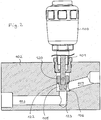
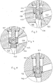
- the Figures 2-5 show the flow control valve 16 in different stages of movement.
- the flow control valve 16 is an electronically controlled valve which has a controllable electric drive 100 which can move a linear movable spindle 101 continuously axially.
- the spindle 101 moves in a valve housing 102, shown here symbolically as a block, through which flow channels 103, 104 pass.
- a closing element 120 is attached to the spindle 101, which more or less opens or closes a flow connection between the flow channels 103 and 104 which merge into one another. This is done continuously.
- the valve comprises a so-called regulating opening 105 in which the closing element 120 can move.
- a valve seat 106 is formed on one edge, more precisely on a kind of shoulder of the regulating opening 105.
- a sealing element 122 is attached to the closing element 120, here in the form of an O-ring. Furthermore, a so-called regulating cone 123 is formed, which tapers conically towards the tip of the closing element 120.
- the regulating cone 123 has a special shape which results in a characteristic flow path. The regulating cone 123 is thus designed and optimized for certain flow characteristics that result from the axial movement of the closing element 120 in the regulating opening 105.
- the so-called control quality is optimized to be small due to flows.
- FIG Figure 4 such a small flow is possible. This is shown by the fact that the released flow cross-section is only slowly increased when the valve is opened. Only when the regulating cone 123 is still about 30-50% of its axial length in the regulating opening 105 does the free flow cross-section change significantly. If the valve is closed, the sealing element 122 is located, as shown in FIG Figure 5 is shown on the valve seat 106 and separates the flow channels 103 and 104 fluid-tight.
- the drive 100 is an electromotive or pneumatic drive.
- the welding cap cooling water control can continuously compensate for the usual fluctuations in the cooling water system, so that an optimal welding result is always achieved.
- the cooling system can continuously be optimally adjusted to match the welding parameters (current strength, sheet metal thickness, number of sheet metal layers, material, welding quality, etc.).
- a diagnosis of the cooling water system can be carried out by actively regulating the flow rate. It can also be the wear and tear of the Welding caps are diagnosed via the position of the closing element 120 or by the setpoint specification of the flow control valve.
Landscapes
- Engineering & Computer Science (AREA)
- Mechanical Engineering (AREA)
- Physics & Mathematics (AREA)
- Optics & Photonics (AREA)
- Thermal Sciences (AREA)
- General Engineering & Computer Science (AREA)
- Valve Housings (AREA)
- Lining Or Joining Of Plastics Or The Like (AREA)
- Safety Valves (AREA)
Description
- Die Erfindung betrifft eine Schweißkappen-Kühlwassersteuerung, mit einer Kühlwasserleitung, die einen in Richtung zur zumindest einer Schweißkappe führenden Kühlwasserzulauf und einen von der Schweißkappe wegführenden Kühlwasserrücklauf hat, wobei im Kühlwasserrücklauf ein schaltbares Steuerventil zum Verschließen des Kühlwasserrücklaufs bei Kappenwechsel sowie zumindest ein Durchflusssensor vorgesehen sind.
- Roboter-Punktschweißanlagen sind insbesondere in der Automobilindustrie im Einsatz und müssen hohen Qualitätsansprüchen gerecht werden. Eine hohe, bis zu 100 % erforderliche Verfügbarkeit erfordert eine maximale Zuverlässigkeit aller Komponenten. Die Schweißkappen unterliegen hohen thermischen Beanspruchungen und Verschleiß und werden durch Kühlwasser permanent gekühlt. Beim Entfernen einer Schweißkappe wird ein im Stand der Technik im Zulauf vorgesehenes 2-2-Wege-Ventil auf ZU geschaltet, zugleich auch das Steuerventil im Rücklauf. Zudem wird eine Wasseraufnahmevorrichtung, beispielsweise ein sich passiv aufweitender Expansionsraum, geöffnet, sodass Wasser aus dem Leitungsabschnitt zwischen den Steuerventilen im Zulauf und im Rücklauf aufgenommen wird. Damit kann aufgrund der sofortigen Druckreduzierung in der Kühlwasserleitung kein unter hohem Druck stehendes Kühlmittel austreten.
- In der
DE 20 2007 011 304 U1 ist eine Schweißkappen-Kühlwassersteuerung mit einem Kühlmittelzulauf zu und einem Kühlmittekrücklauf von den Schweißkappen einer Schweißvorrichtung gezeigt. Die Vorrichtung hat zwei Ventile zum Absperren eines Teils des Kühlkreislaufs, in dem sich die Schweißkappen befinden, sowie eine Steuerung zur Ansteuerung der Ventile. Diese Druckschrift offenbart die Merkmale des Oberbegriffes des Anspruchs 1. - Aus der
DE 10 2013 200 994 A1 und derWO 88/09574 A2 - Aufgabe der Erfindung ist es, ohne erwähnenswerten finanziellen Mehraufwand die Kühlwassersteuerung zu verbessern.
- Dies wird bei einer Schweißkappen-Kühlwassersteuerung nach Anspruch 1 dadurch erreicht, dass im Kühlwasserzulauf oder -rücklauf ein elektronisch gesteuertes Durchflussregelventil sitzt. Das Durchflussregelventil weist dabei ein Schließelement mit einem Regelkegel auf, der zur Spitze des Schließelements konisch zuläuft. Der Regelkegel hat eine spezielle Form, die einen charakteristischen Durchfluss-Weg ergibt. Damit ist der Regelkegel auf bestimmte Durchflusscharakteristika ausgelegt und optimiert, die sich durch die Axialbewegung des Schließelements in einer Regelöffnung des Durchflussregelventils ergibt. Dieses Durchflussregelventil regelt die Kühlwassermenge, die zur Schweißkappe oder den Schweißkappen fließt. Das elektronisch gesteuerte Durchflussregelventil ersetzt das bisher im Zulauf sitzende Steuerventil und schafft es, den Wasserverbrauch zu reduzieren, weil tatsächlich nur die Kühlwassermenge hindurchgepumpt wird, die zur optimalen Kühlung notwendig ist. Auch die Umwälzpumpenleistung kann reduziert werden, bei gleichzeitig reduziertem Serviceaufwand. Darüber hinaus werden die bislang im Kühlwasserkreislauf notwendigen und vorkommenden sogenannten Schließschläge vermieden. Diese durch den abrupten Schaltvorgang eines Steuerventils auftretenden Schläge in der Kühlwasserleitung konnten auch einen Schweißkappenverlust hervorrufen, was durch die erfindungsgemäße Schutzkappen-Kühlwassersteuerung vermieden wird. Durch das Durchflussregelventil steht der Schweißkappe oder stehen den mehreren Schweißkappen, die von einer Kühlleitung gekühlt werden, von Anfang an die exakten, notwendigen Kühlwassermengen zur Verfügung, obwohl der Leitungswiderstand und/oder Systemdruck ständig geändert werden. Dies ist insbesondere dann der Fall, wenn die Schweißkappe auf einem Roboter sitzt, der mit flexiblen Kühlschläuchen gekoppelt wird oder beispielsweise weitere Anlagen zu- oder abgeschaltet werden. Diese Kühlschläuche werden bei den Bewegungen des Roboters gebogen, gegebenenfalls gestaucht, sodass die Kühlwasserleitung unterschiedliche Widerstände während des Betriebs hat. Diese Widerstände werden durch das Durchflussregelventil sofort ausgeglichen.
- Aufgrund der im Durchschnitt geringeren Pumpenleistung können kostengünstigere Pumpen eingebaut werden, und im Dauerlauf kann der Stromverbrauch reduziert werden. Durch die reproduzierbare Kühlleistungszuführung kann auch die Schweißqualität nachhaltig verbessert werden und permanent auf hohem Niveau bleiben.
- Vorzugsweise ist eine Steuerungseinheit vorgesehen, die mit dem zumindest einen Durchflusssensor, dem Steuerventil und dem Durchflussregelventil gekoppelt ist und diese steuert oder von diesen Daten aufnimmt. Hierdurch ist es möglich, dass der ohnehin vorgesehene Durchflusssensor für die Steuerung des Durchflussregelventils herangezogen wird, sodass auch hier kein Mehraufwand getrieben werden muss.
- Der Durchflusssensor sitzt, wie gesagt, insbesondere in der Rücklaufleitung und kann die Durchströmmenge, die Wassertemperatur und/oder den Druck detektieren. Über den Durchflusssensor können dann auch Veränderungen im Druck bzw. Durchfluss sofort detektiert werden, die gegebenenfalls auch auf ein Leck in der Kühlwasserleitung schließen lassen. Die Steuerung ist dabei so programmiert, dass sie ab Unterschreiten eines vorbestimmten Drucks oder Durchflusses auf ein solches Leck schließt und damit einen Alarm auslöst. Bisher vorgesehene zusätzliche Vorrichtungen, die ein solches Leck detektierten und anzeigten, sind jetzt überflüssig, denn ein solches Alarmsystem ist einfach steuerungstechnisch in der erfindungsgemäßen Kühlwassersteuerung realisierbar.
- Ferner sollte eine schaltbare Wasseraufnahmevorrichtung vorhanden sein, die bei Kappenwechsel elektrisch betätigbar und Kühlwasser aus einem Leitungsabschnitt zwischen dem Durchflussregelventil und dem Steuerventil aufnimmt. Dies dient, wie gesagt, dazu, eine sofortige Druckreduzierung in der Kühlwasserleitung herbeiführen zu können.
- Die Wasseraufnahmevorrichtung umfasst einen Expansionsraum, der eine bewegliche Wand besitzt, die insbesondere mit einem einstellbaren Gegendruck zum Wasserdruck im Leitungsabschnitt beaufschlagbar ist. Im einfachsten Fall ist der Expansionsraum Teil einer Kolben-Zylinder-Einheit, wobei der Expansionsraum auf einer Seite des Kolbens liegt und der Gegendruck in dem Raum auf der anderen Seite des Kolbens aufgebaut wird. Dies kann beispielsweise dadurch erfolgen, dass eine hydraulische oder pneumatische Leitung in diesen Raum mündet, wobei hier auch vorzugsweise ein einstellbares Drosselventil vorgesehen sein kann und/oder ein Vorschaltventil. Dadurch lässt sich der Gegendruck einfach einstellen.
- Alternativ hierzu könnte auch eine aktive Wasseraufnahmevorrichtung angekoppelt sein, die durch einen motorisch angetriebenen Kolben oder einen durch Unterdruck beweglichen Kolben oder einen hydraulisch oder pneumatisch angetriebenen Kolben umfasst. Dieser Kolben wird aktiv bewegt, wenn es zu einer Leckage kommt, sodass er Kühlwasser aus der Kühlwasserleitung saugt.
- Die Steuerungseinheit ist vorzugsweise so ausgebildet und programmiert, dass Zulaufseitig nur das Durchflussregelventil bei Kappenwechsel und/oder Leckage in der Kühlwasserleitung elektrisch geschaltet wird, um den Zulauf von Kühlwasser zu stoppen. Zusätzliche Steuerventile sind damit überflüssig. Das Durchflussregelventil wird einfach auf ZU geschaltet.
- Die erfindungsgemäße Kühlwassersteuerung ist so ausgebildet, dass sie auch mehrere Schweißkappen, die nacheinander strömungsdurchflossen werden, kühlt. Das Kühlmittel strömt also an oder durch mehrere Schweißkappen.
- Das Durchflussregelventil steuert dabei für sämtliche in der Kühlwasserleitung vorgesehenen Schweißkappen die Kühlwassermenge, das heißt, es ist nur ein Durchflussregelventil gemäß einer vorzugsweisen Ausgestaltung der Erfindung vorgesehen. Dieses Durchflussregelventil sollte vor der ersten Schweißkappe angeordnet sein.
- Ist das Durchflussregelventil im Rücklauf angeordnet, sollte im Zulauf ein Abschaltventil positioniert sein, das bei Schweißkappenwechsel wie das Durchflussregelventil schließt.
- Es können ein oder mehrere Durchflusssensoren vorgesehen sein, beispielsweise insgesamt nur ein Durchflusssensor, der vor dem nach der letzten Schweißkappe sitzenden Steuerventil angeordnet ist, oder es können zwischen dem Durchflussregelventil und dem Steuerventil mehrere Durchflusssensoren vorhanden sein. Beispielsweise kann auch für jede Schweißkappe ein eigener Durchflusssensor eingesetzt werden, was im Normalfall jedoch unnötig ist.
- Die Steuerungseinheit ist so ausgebildet, dass sie bei einem durch den Durchflusssensor erfassten Druckabfall unter einen vorbestimmten Wert das Regelventil aktiv ansteuert und schließt. Somit hat der Durchflusssensor mehrere Funktionen. Er dient dazu, den Durchfluss des Kühlwassers für die Anpassung der Durchflussmenge zu ermitteln. Zudem ist er Teil des Alarmsystems, welches eine Leckage aufdeckt.
- Bei der Kühlwassersteuerung der vorliegenden Erfindung wird die Kühlwassermenge automatisch auch dann noch auf den optimalen Wert geregelt, wenn weitere Verbraucher hinzukommen, Verbraucher (Schweißroboter) deaktiviert sind oder die Kühlwasserleitung aufgrund von Bewegungen des Roboters andere Widerstände aufweist.
- Das Durchflussregelventil kann stufenlos geöffnet und geschlossen werden, gegebenenfalls auch vollständig geschlossen werden.
- Weitere Merkmale und Vorteile ergeben sich aus der nachfolgenden Beschreibung und aus der nachfolgenden Zeichnung, auf die Bezug genommen wird.
- -
Figur 1 zeigt ein Schaltbild der erfindungsgemäßen Schweißkappen-Kühlwassersteuerung, -
Figur 2 zeigt eine Schnittansicht durch das Durchflussregelventil, welches bei der erfindungsgemäßen Schweißkappen-Kühlwassersteuerung eingesetzt wird, und - die
Figuren 3 bis 5 zeigen aufeinanderfolgende Stadien bei der Bewegung des Durchflussregelventils nachFigur 2 von der offenen in die teilweise offene und schließlich in die geschlossene Stellung. - In
Figur 1 ist eine Schutzkappen-Kühlwassersteuerung für eine oder mehrere Schweißkappen 10, die an einem Schweißroboter bzw. mehreren Schweißrobotern sitzen, dargestellt. Beispielhaft sind Reihen- und Parallelanordnungen von Schweißkappen dargestellt. Eine Kühlwasserleitung ist als Kreislauf ausgeführt und umfasst einen Kühlwasserzulauf 12 sowie einen Kühlwasserrücklauf 14, die zu bzw. weg von den Schweißkappen 10 führen. - Sind mehrere Schweißkappen 10 vorhanden, die mit einer Schweißkappen-Kühlwassersteuerung gekühlt werden, so ergibt sich strömungstechnisch vorzugsweise eine Reihenschaltung der Schweißkappen 10 in der Kühlwasserleitung.
- Im Kühlwasserzulauf 12 sitzt ein elektronisch betätigbares und steuerbares Durchflussregelventil 16, und zwar vor der ersten Schweißkappe 10. Zwischen der ersten Schweißkappe 10 und dem Durchflussregelventil 16 zweigt vom Kühlwasserzulauf eine zu einer Wasseraufnahmevorrichtung 18 führende Leitung (Blindleitung) ab. Optional kann das Durchflussregelventil 16 im Rücklauf 14 sitzen, wie mit dem mit unterbrochenen Linien gezeigten Pfeil symbolisiert. An der Position des Durchflussregelventils 16 im Zulauf 12 ist ein Abschaltventil angeordnet.
- Nach der letzten Schweißkappe 10 ist ein Durchflusssensor 20 in der Kühlwasserrücklaufleitung 14 angeordnet, und nach dem Durchflusssensor ein elektrisch schaltbares Steuerventil 22, hier ein 2-2-Wege-Ventil. Dieses Steuerventil ist federbelastet, und zwar in eine geschlossene Position. Natürlich könnte bei Energieausfall auch eine offene Stellung vorgesehen sein.
- Steuerungsseitig ist eine sogenannte PLC, auch SPS genannt, mit einem nachgeschalteten PID-Regler gekoppelt. Vorzugsweise wird die PLC anlagenseitig, das heißt vom Anlagenbetreiber, gestellt, wogegen die PID mit einer Steuerungseinheit 24 der Kühlwassersteuerung gekoppelt ist oder einen Teil derselben bildet.
- Das Durchflussregelventil 16, die Wasseraufnahmevorrichtung 18, der Durchflusssensor 20 sowie das Steuerventil 22 sind mit der Steuerungseinheit 24 elektrisch gekoppelt und senden Daten bzw. erhalten Steuerdaten von der Steuerungseinheit 24. Die entsprechende Leitungsführung ist in
Figur 1 dargestellt. - Die Steuerungseinheit 24 steuert beispielsweise Hydraulik- oder Pneumatikventile 26, die wiederum das Durchflussregelventil 16 ansteuern.
- Darüber hinaus wird die Wasseraufnahmevorrichtung 18 gesteuert. Im dargestellten Ausführungsbeispiel umfasst die Wasseraufnahmevorrichtung 18 einen Zylinder 30, in dem sich ein verschiebbarer Kolben 32 als bewegliche Wand befindet. Der rechte, vom Kolben 32 im Zylinder 30 abgetrennte Raum ist mit dem Kühlwasserzulauf 12 gekoppelt, und der entgegengesetzte Raum mit einer Leitung 34, in der eine Drossel 36 sitzt. Die Leitung 34 führt zu einem Vorsteuerventil 38, welches die Leitung 34 entweder zur Umgebung öffnet oder von ihr abtrennt. Die Leitung 34 wird entweder druckbeaufschlagt oder entlüftet.
- Abhängig von den Daten, die der Durchflusssensor 20 liefert, steuert die Steuerungseinheit 24 das Durchflussregelventil 16 an, um dieses proportional zu öffnen oder zu schließen.
- Das Durchflussregelventil 16 kann stufenlos geöffnet und geschlossen werden, gegebenenfalls auch vollständig geschlossen werden.
- Abhängig vom Widerstand in der Kühlwasserleitung, von der Anzahl der zu kühlenden Schweißkappen 10 und auch von der Kühlwassertemperatur (insbesondere in der Rücklaufleitung), wird der optimale Kühlwasserdurchfluss im Durchflussregelventil 16 eingestellt.
- Eine nicht dargestellte, aber auch über die Steuerungseinheit 24 angesteuerte Pumpe kann zusätzlich stufenlos stärker oder weniger stark betrieben werden, um Kühlwasser durch die Kühlwasserleitung strömen zu lassen.
- Nicht dargestellt sind in diesem Zusammenhang auch eventuelle Temperatursensoren, die möglichst im oder in der Nähe des Durchflusssensors 20 angeordnet sind, sodass nicht nur die Strömungsmenge, sondern auch die Temperatur des Kühlwassers detektiert und in der Steuerungseinheit 24 zur Einstellung des Durchflussregelventils 16 berücksichtigt wird.
- Wird eine Leckage durch abrupten Durchflussrückgang, beispielsweise im Durchflusssensor 20, detektiert, steuert die Steuereinheit 24 sofort das Durchflussregelventil 16 an, das dafür verantwortlich ist, vorzugsweise alleine dafür verantwortlich ist, den Zufluss von Kühlmittel zu den Schweißkappen 10 zu unterbinden. Entsprechend wird auch das Steuerventil 22 auf ZU geschaltet.
- Im Falle eines Druckabfalls wird ferner das Vorsteuerventil 38 angesteuert, welches den Raum links vom Kolben 32 mit der Umgebung koppelt, sodass der Überdruck im Leitungsabschnitt zwischen dem Durchflussregelventil 16 und dem Steuerventil 22 dazu führt, dass der Kolben 32 nach links gedrückt wird. Druckspitzen werden somit sofort abgebaut.
- Der im linken Raum im Zylinder 30 vorhandene Druckverlauf ist einstellbar, nämlich über die Drossel 36, gegebenenfalls auch über ein Regelventil als Vorsteuerventil 38.
- Werden mehr Schweißkappen 10 angeschlossen, wird über den Durchflusssensor 20 oder über die mehreren Sensoren an dieser Stelle detektiert, dass mehr Kühlleistung zur Verfügung gestellt werden muss, und die Steuerungseinheit 24 steuert das Regelventil 16 und gegebenenfalls die Pumpe entsprechend an, um mehr Kühlwasser zuzuführen.
- Die
Figuren 2-5 zeigen das Durchflussregelventil 16 in verschiedenen Bewegungsstadien. - Es handelt sich beim Durchflussregelventil 16 um ein elektronisch gesteuertes Ventil, welches einen steuerbaren elektrischen Antrieb 100 aufweist, der eine lineare bewegliche Spindel 101 stufenlos axial verschieben kann.
- Die Spindel 101 bewegt sich in einem hier symbolisch als Block dargestellten Ventilgehäuse 102, welches von Strömungskanälen 103,104 durchsetzt wird. An der Spindel 101 ist ein Schließelement 120 angebracht, welches eine Strömungsverbindung zwischen den ineinander übergehenden Strömungskanälen 103 und 104 mehr oder weniger freigibt oder schließt. Dies erfolgt stufenlos.
- Das Ventil umfasst eine sogenannte Regelöffnung 105, in der sich das Schließelement 120 bewegen kann. An einem Rand, genauer gesagt an einer Art Schulter der Regelöffnung 105 ist ein Ventilsitz 106 ausgebildet.
- Am Schließelement 120 ist ein Dichtelement 122 angebracht, hier in Form eines O-Rings. Ferner ist ein so genannter Regelkegel 123 ausgeformt, der zur Spitze des Schließelements 120 konisch zuläuft. Der Regelkegel 123 hat eine spezielle Form, die einen charakteristischen Durchfluss-Weg ergibt. Damit ist der Regelkegel 123 auf bestimmte Durchflusscharakteristika ausgelegt und optimiert, die sich durch die Axialbewegung des Schließelements 120 in der Regelöffnung 105 ergibt.
- Im gezeigten Ausführungsbeispiel ist die sogenannte Regelgüte auf kleine durch Flüsse hin optimiert. In
Figur 4 ist ein solcher kleiner Durchfluss möglich. Dies zeigt sich dadurch, dass der freigegebene Strömungsquerschnitt beim Öffnen des Ventils nur langsam erhöht wird. Erst wenn der Regelkegel 123 noch zu ca. 30-50 % seiner axialen Länge in der Regelöffnung 105 eintaucht, ändert sich der freie Strömungsquerschnitt deutlich. Wird das Ventil geschlossen, liegt der dass Dichtelement 122, wie dies inFigur 5 gezeigt ist, am Ventilsitz 106 an und trennt die Strömungskanäle 103 und 104 fluiddicht. - Der Antrieb 100 ist ein elektromotorischer oder pneumatischer Antrieb. Die Schweißkappen-Kühlwassersteuerung kann die üblichen Schwankungen im Kühlwassersystem fortlaufend ausgleichen, sodass stets ein optimales Schweißergebnis erreicht wird. Mit dem dargestellten Durchflussregelventil 16 kann das Kühlsystem laufend passend zu den Schweißparametern (Stromstärke, Blechdicke, Anzahl der Blechlagen, Material, Schweißgüte usw.) optimal eingestellt werden. Zudem kann durch die aktive Regelung des Durchflusses eine Diagnose des Kühlwassersystems durchgeführt werden. Es kann auch der Verschleiß der Schweißkappen über die Stellung des Schließelements 120 bzw. durch die Sollwertvorgabe des Durchflussregelventils diagnostiziert werden.
Claims (10)
- Schweißkappen-Kühlwassersteuerung, mit einer Kühlwasserleitung, die einen in Richtung zu zumindest einer Schweißkappe (10) führenden Kühlwasserzulauf (12) und einen von der zumindest einen Schweißkappe (10) wegführenden Kühlwasserrücklauf (14) aufweist, wobei im Kühlwasserrücklauf (14) ein schaltbares Steuerventil (22) zum Verschließen des Kühlwasserrücklaufs (14) bei Kappenwechsel sowie zumindest ein Durchflusssensor (20) vorgesehen sind, dadurch gekennzeichnet, dass im Kühlwasserzulauf (12) oder Kühlwasserrücklauf (14) ein elektronisch gesteuertes Durchflussregelventil (16) sitzt, wobei das Durchflussregelventil (16) ein Ventilgehäuse (102) mit ineinander übergehenden Strömungskanälen (103, 104), eine lineare bewegliche Spindel (101) mit einem Schließelement (120), ein am Schließelement (120) angebrachtes Dichtelement (122) und einen steuerbaren elektrischen Antrieb (100) aufweist, wobei das Durchflussregelventil (16) eine Regelöffnung (105), in der sich das Schließelement (120) bewegen kann, mit einem Ventilsitz (106) hat, wobei die Spindel (101) mittels des elektrischen Antriebs (100) stufenlos axial verschiebbar ist, so dass das Schließelement (120) eine Strömungsverbindung zwischen den ineinander übergehenden Strömungskanälen (103, 104) stufenlos mehr oder weniger freigibt oder schließt, und wobei das Schließelement (120) einen Regelkegel (123) aufweist, der zur Spitze des Schließelements (120) konisch zuläuft.
- Schweißkappen-Kühlwassersteuerung nach Anspruch 1, dadurch gekennzeichnet, dass eine Steuerungseinheit (24) vorgesehen ist, die mit dem Durchflusssensor (20), dem Steuerventil (22) und dem Durchflussregelventil (16) gekoppelt ist und diese steuert oder Daten von diesen aufnimmt.
- Schweißkappen-Kühlwassersteuerung nach Anspruch 2, dadurch gekennzeichnet, dass die Steuerungseinheit (24) einen PID-Regler aufweist.
- Schweißkappen-Kühlwassersteuerung nach einem der vorhergehenden Ansprüche, dadurch gekennzeichnet, dass eine schaltbare Wasseraufnahmevorrichtung (18) vorhanden ist, die bei Kappenwechsel elektrisch betätigbar ist und Kühlwasser aus einem Leitungsabschnitt zwischen dem Durchflussregelventil (16) und dem Steuerventil (22) aufnimmt.
- Schweißkappen-Kühlwassersteuerung nach Anspruch 4, dadurch gekennzeichnet, dass die Wasseraufnahmevorrichtung (18) einen Expansionsraum aufweist, der eine bewegliche Wand besitzt, die insbesondere mit einem einstellbaren Gegendruck zum Wasserdruck des Kühlwassers im Leitungsabschnitt beaufschlagbar ist.
- Schweißkappen-Kühlwassersteuerung nach Anspruch 4 oder 5, dadurch gekennzeichnet, dass die Wasseraufnahmevorrichtung (18) mit einem Vorsteuerventil (38) beaufschlagt ist.
- Schweißkappen-Kühlwassersteuerung nach einem der vorhergehenden Ansprüche, soweit auf Anspruch 2 rückbezogen, dadurch gekennzeichnet, dass die Steuerungseinheit (24) so ausgebildet und programmiert ist, dass zulaufseitig nur das Durchflussregelventil bei Kappenwechsel und/oder bei Leckage in der Kühlwasserleitung elektrisch geschaltet wird, um den Zulauf von Kühlwasser zu der wenigstens einen Schweißkappe zu stoppen.
- Schweißkappen-Kühlwassersteuerung nach einem der vorhergehenden Ansprüche, dadurch gekennzeichnet, dass die Kühlwasserleitung an mehreren Schweißkappen (10) nacheinander entlangführt, um diese zu kühlen.
- Schweißkappen-Kühlwassersteuerung nach Anspruch 8, dadurch gekennzeichnet, dass nur ein Durchflussregelventil (16) vorhanden ist, das insbesondere im Zulauf zur ersten Schweißkappe (10) angeordnet ist.
- Schweißkappen-Kühlwassersteuerung nach einem der vorhergehenden Ansprüche, dadurch gekennzeichnet, dass mehrere Schweißkappen (10) über die Kühlwasserleitung gekühlt werden und dass insgesamt nur ein einziger oder mehrere Durchflusssensoren vorhanden sind oder dass stromabwärts insbesondere jeder Schweißkappe (10) ein zugeordneter Durchflusssensor (20) vorhanden ist, wobei die Steuerungseinheit (24) so ausgebildet ist, dass bei durch den zumindest einen Durchflusssensor (20) detektiertem Druckabfall unter einen vorbestimmten Druck das Durchflussregelventil (16) geschlossen wird.
Applications Claiming Priority (1)
| Application Number | Priority Date | Filing Date | Title |
|---|---|---|---|
| DE102015120222.0A DE102015120222A1 (de) | 2015-11-23 | 2015-11-23 | Schweißkappen-Kühlwassersteuerung |
Publications (3)
| Publication Number | Publication Date |
|---|---|
| EP3170608A2 EP3170608A2 (de) | 2017-05-24 |
| EP3170608A3 EP3170608A3 (de) | 2017-08-09 |
| EP3170608B1 true EP3170608B1 (de) | 2021-05-05 |
Family
ID=57345728
Family Applications (1)
| Application Number | Title | Priority Date | Filing Date |
|---|---|---|---|
| EP16198906.6A Active EP3170608B1 (de) | 2015-11-23 | 2016-11-15 | Schweisskappen-kühlwassersteuerung |
Country Status (4)
| Country | Link |
|---|---|
| US (1) | US20170144245A1 (de) |
| EP (1) | EP3170608B1 (de) |
| CN (1) | CN107009016A (de) |
| DE (1) | DE102015120222A1 (de) |
Families Citing this family (5)
| Publication number | Priority date | Publication date | Assignee | Title |
|---|---|---|---|---|
| CN108274104A (zh) * | 2017-12-25 | 2018-07-13 | 凌云工业股份(芜湖)有限公司 | 一种双手联动点焊操作系统及其操作方法 |
| CN108637533A (zh) * | 2018-04-17 | 2018-10-12 | 江铃控股有限公司 | 焊接冷却系统及使用该焊接冷却系统的焊装机器人 |
| CN109262126B (zh) * | 2018-11-02 | 2022-08-02 | 广州市极动焊接机械有限公司 | 冷却水防落装置 |
| DE102019204208B4 (de) * | 2019-02-28 | 2024-08-01 | Christian Günther | Vorrichtung zur Kühlwasserabsaugung für eine Roboterinstallationsplatte mit einstellbarem Absaugvolumen |
| DE102020124846B4 (de) | 2020-09-23 | 2024-05-23 | Bürkert Werke GmbH & Co. KG | Schweißkappen-Kühlwassersteuerung sowie Verfahren zur Steuerung einer Schweißkappen-Kühlwassersteuerung |
Family Cites Families (12)
| Publication number | Priority date | Publication date | Assignee | Title |
|---|---|---|---|---|
| US4940873A (en) * | 1987-05-22 | 1990-07-10 | Davies Joseph R | Roller electrodes for electric-resistance welding machine |
| US5719367A (en) * | 1996-05-03 | 1998-02-17 | Syndevco, Inc. | Welding gun coolant control valve assembly |
| US6455800B1 (en) * | 2001-01-04 | 2002-09-24 | Festo Corporation | Servo-pneumatic modular weld gun |
| US20050173380A1 (en) * | 2004-02-09 | 2005-08-11 | Carbone Frank L. | Directed energy net shape method and apparatus |
| DE202005009866U1 (de) * | 2005-06-23 | 2005-10-06 | REU-Schweißtechnik GmbH | Steuervorrichtung einer Schweißzangen-Kühleinrichtung |
| DE202007011304U1 (de) * | 2007-08-13 | 2007-10-11 | Bürkert Werke GmbH & Co. KG | Vorrichtung zur Überwachung eines Kühlkreislaufs |
| CN102886630B (zh) * | 2012-07-18 | 2014-10-01 | 奇瑞汽车股份有限公司 | 一种机器人点焊系统及其控制方法 |
| DE102013200994A1 (de) * | 2013-01-22 | 2014-07-24 | Dieter Klein | Verfahren zum Kühlen einer Elektrodenkappe in einer Schweißanlage undSchweißanlage zur Durchführung des Verfahrens |
| DE102013101104A1 (de) * | 2013-02-05 | 2014-08-07 | Bürkert Werke GmbH | Kühlanordnung zum Kühlen eines Objekts mit einer Kontrolleinrichtung und Verfahren zur Überwachung einer solchen Kühlanordnung |
| US9821415B2 (en) * | 2014-03-28 | 2017-11-21 | Crc-Evans Pipeline International, Inc. | Internal pipeline cooler |
| EP3065909B1 (de) * | 2013-11-08 | 2024-02-21 | Thermatool Corp. | Wärmeenergieerfassung und -analyse für schweissverfahren |
| CN204719557U (zh) * | 2015-06-04 | 2015-10-21 | 北京自动化技术研究院 | 一种温控设备的冷却控制系统 |
-
2015
- 2015-11-23 DE DE102015120222.0A patent/DE102015120222A1/de not_active Withdrawn
-
2016
- 2016-11-15 EP EP16198906.6A patent/EP3170608B1/de active Active
- 2016-11-23 US US15/360,414 patent/US20170144245A1/en not_active Abandoned
- 2016-11-23 CN CN201611037483.8A patent/CN107009016A/zh active Pending
Also Published As
| Publication number | Publication date |
|---|---|
| EP3170608A3 (de) | 2017-08-09 |
| CN107009016A (zh) | 2017-08-04 |
| US20170144245A1 (en) | 2017-05-25 |
| EP3170608A2 (de) | 2017-05-24 |
| DE102015120222A1 (de) | 2017-05-24 |
Similar Documents
| Publication | Publication Date | Title |
|---|---|---|
| DE650404C (de) | Vorrichtung zur Steuerung der Bewegung eines durch Fluessigkeit beeinflussten Teiles | |
| EP2638297B1 (de) | Hydraulischer oder pneumatischer antrieb zur betätigung einer armatur mit einem regel- oder schaltventil | |
| EP3535509B1 (de) | Kugelhahn für ein leitungssystem zur förderung von flüssigen oder gasförmigen medien | |
| EP3170608A2 (de) | Schweisskappen-kühlwassersteuerung | |
| EP1860328A1 (de) | Einrichtung zur Steuerung eines pneumatischen, insbesondere doppelwirkenden, Zylinders | |
| DE102012016838A1 (de) | Hydraulische Steuerschaltung für eine hydraulisch betätigte Gießeinheit | |
| WO2009062558A1 (de) | Ventilvorrichtung | |
| AT516316A2 (de) | Hydraulische Schaltung und Maschine mit einer hydraulischen Schaltung | |
| DE102010048901A1 (de) | Elektromotorisch betätigtes Ventil | |
| DE102013101104A1 (de) | Kühlanordnung zum Kühlen eines Objekts mit einer Kontrolleinrichtung und Verfahren zur Überwachung einer solchen Kühlanordnung | |
| EP3140071B1 (de) | Vorrichtung zur kühlmittelversorgung, steuerung für eine solche vorrichtung und verfahren zum betrieb einer solchen kühlmittelversorgung | |
| EP3123022B1 (de) | Mengenbegrenzungsventil, insbesondere für ein dual-fuel-kraftstoffeinspritzsystem | |
| EP3353385B1 (de) | Turbine mit schnellschluss- und regelventilen | |
| EP3135924B1 (de) | Hydrauliksteuerung | |
| EP2808109B1 (de) | Spannsystem | |
| WO2017186712A1 (de) | Hydraulische achse für eine presse | |
| DE102005029822A1 (de) | Hydraulische Umformanlage | |
| DE102016002834A1 (de) | Ventil mit einer Überwachungsfunktion | |
| DE202007011304U1 (de) | Vorrichtung zur Überwachung eines Kühlkreislaufs | |
| EP4390198A1 (de) | Vorrichtung und verfahren zur durchflussregelung eines fluids | |
| DE102016114727A1 (de) | Gleichlaufsteuerung für ein Hydraulikzylindersystem | |
| DE2753439C2 (de) | ||
| DE2611088C3 (de) | Steuereinrichtung für einen hydraulischen Arbeitzylinder mit einem Differentialkolben | |
| DE102012209528A1 (de) | Hydrauliksteuerungsvorrichtung mit einem digitalhydraulischen regler | |
| DE102009019068B4 (de) | Drucküberwachungsschaltung |
Legal Events
| Date | Code | Title | Description |
|---|---|---|---|
| PUAI | Public reference made under article 153(3) epc to a published international application that has entered the european phase |
Free format text: ORIGINAL CODE: 0009012 |
|
| STAA | Information on the status of an ep patent application or granted ep patent |
Free format text: STATUS: THE APPLICATION HAS BEEN PUBLISHED |
|
| AK | Designated contracting states |
Kind code of ref document: A2 Designated state(s): AL AT BE BG CH CY CZ DE DK EE ES FI FR GB GR HR HU IE IS IT LI LT LU LV MC MK MT NL NO PL PT RO RS SE SI SK SM TR |
|
| AX | Request for extension of the european patent |
Extension state: BA ME |
|
| PUAL | Search report despatched |
Free format text: ORIGINAL CODE: 0009013 |
|
| AK | Designated contracting states |
Kind code of ref document: A3 Designated state(s): AL AT BE BG CH CY CZ DE DK EE ES FI FR GB GR HR HU IE IS IT LI LT LU LV MC MK MT NL NO PL PT RO RS SE SI SK SM TR |
|
| AX | Request for extension of the european patent |
Extension state: BA ME |
|
| RIC1 | Information provided on ipc code assigned before grant |
Ipc: B23K 11/36 20060101ALI20170704BHEP Ipc: B23K 37/00 20060101ALI20170704BHEP Ipc: B23K 11/10 20060101AFI20170704BHEP |
|
| STAA | Information on the status of an ep patent application or granted ep patent |
Free format text: STATUS: REQUEST FOR EXAMINATION WAS MADE |
|
| 17P | Request for examination filed |
Effective date: 20171129 |
|
| RBV | Designated contracting states (corrected) |
Designated state(s): AL AT BE BG CH CY CZ DE DK EE ES FI FR GB GR HR HU IE IS IT LI LT LU LV MC MK MT NL NO PL PT RO RS SE SI SK SM TR |
|
| STAA | Information on the status of an ep patent application or granted ep patent |
Free format text: STATUS: EXAMINATION IS IN PROGRESS |
|
| 17Q | First examination report despatched |
Effective date: 20200211 |
|
| GRAP | Despatch of communication of intention to grant a patent |
Free format text: ORIGINAL CODE: EPIDOSNIGR1 |
|
| STAA | Information on the status of an ep patent application or granted ep patent |
Free format text: STATUS: GRANT OF PATENT IS INTENDED |
|
| INTG | Intention to grant announced |
Effective date: 20201124 |
|
| GRAS | Grant fee paid |
Free format text: ORIGINAL CODE: EPIDOSNIGR3 |
|
| GRAA | (expected) grant |
Free format text: ORIGINAL CODE: 0009210 |
|
| STAA | Information on the status of an ep patent application or granted ep patent |
Free format text: STATUS: THE PATENT HAS BEEN GRANTED |
|
| AK | Designated contracting states |
Kind code of ref document: B1 Designated state(s): AL AT BE BG CH CY CZ DE DK EE ES FI FR GB GR HR HU IE IS IT LI LT LU LV MC MK MT NL NO PL PT RO RS SE SI SK SM TR |
|
| REG | Reference to a national code |
Ref country code: GB Ref legal event code: FG4D Free format text: NOT ENGLISH |
|
| REG | Reference to a national code |
Ref country code: CH Ref legal event code: EP |
|
| REG | Reference to a national code |
Ref country code: AT Ref legal event code: REF Ref document number: 1389190 Country of ref document: AT Kind code of ref document: T Effective date: 20210515 |
|
| REG | Reference to a national code |
Ref country code: IE Ref legal event code: FG4D Free format text: LANGUAGE OF EP DOCUMENT: GERMAN |
|
| REG | Reference to a national code |
Ref country code: DE Ref legal event code: R096 Ref document number: 502016012963 Country of ref document: DE |
|
| REG | Reference to a national code |
Ref country code: LT Ref legal event code: MG9D |
|
| PG25 | Lapsed in a contracting state [announced via postgrant information from national office to epo] |
Ref country code: FI Free format text: LAPSE BECAUSE OF FAILURE TO SUBMIT A TRANSLATION OF THE DESCRIPTION OR TO PAY THE FEE WITHIN THE PRESCRIBED TIME-LIMIT Effective date: 20210505 Ref country code: LT Free format text: LAPSE BECAUSE OF FAILURE TO SUBMIT A TRANSLATION OF THE DESCRIPTION OR TO PAY THE FEE WITHIN THE PRESCRIBED TIME-LIMIT Effective date: 20210505 Ref country code: BG Free format text: LAPSE BECAUSE OF FAILURE TO SUBMIT A TRANSLATION OF THE DESCRIPTION OR TO PAY THE FEE WITHIN THE PRESCRIBED TIME-LIMIT Effective date: 20210805 Ref country code: HR Free format text: LAPSE BECAUSE OF FAILURE TO SUBMIT A TRANSLATION OF THE DESCRIPTION OR TO PAY THE FEE WITHIN THE PRESCRIBED TIME-LIMIT Effective date: 20210505 |
|
| PG25 | Lapsed in a contracting state [announced via postgrant information from national office to epo] |
Ref country code: GR Free format text: LAPSE BECAUSE OF FAILURE TO SUBMIT A TRANSLATION OF THE DESCRIPTION OR TO PAY THE FEE WITHIN THE PRESCRIBED TIME-LIMIT Effective date: 20210806 Ref country code: LV Free format text: LAPSE BECAUSE OF FAILURE TO SUBMIT A TRANSLATION OF THE DESCRIPTION OR TO PAY THE FEE WITHIN THE PRESCRIBED TIME-LIMIT Effective date: 20210505 Ref country code: IS Free format text: LAPSE BECAUSE OF FAILURE TO SUBMIT A TRANSLATION OF THE DESCRIPTION OR TO PAY THE FEE WITHIN THE PRESCRIBED TIME-LIMIT Effective date: 20210905 Ref country code: PT Free format text: LAPSE BECAUSE OF FAILURE TO SUBMIT A TRANSLATION OF THE DESCRIPTION OR TO PAY THE FEE WITHIN THE PRESCRIBED TIME-LIMIT Effective date: 20210906 Ref country code: NO Free format text: LAPSE BECAUSE OF FAILURE TO SUBMIT A TRANSLATION OF THE DESCRIPTION OR TO PAY THE FEE WITHIN THE PRESCRIBED TIME-LIMIT Effective date: 20210805 Ref country code: PL Free format text: LAPSE BECAUSE OF FAILURE TO SUBMIT A TRANSLATION OF THE DESCRIPTION OR TO PAY THE FEE WITHIN THE PRESCRIBED TIME-LIMIT Effective date: 20210505 Ref country code: SE Free format text: LAPSE BECAUSE OF FAILURE TO SUBMIT A TRANSLATION OF THE DESCRIPTION OR TO PAY THE FEE WITHIN THE PRESCRIBED TIME-LIMIT Effective date: 20210505 Ref country code: RS Free format text: LAPSE BECAUSE OF FAILURE TO SUBMIT A TRANSLATION OF THE DESCRIPTION OR TO PAY THE FEE WITHIN THE PRESCRIBED TIME-LIMIT Effective date: 20210505 |
|
| REG | Reference to a national code |
Ref country code: NL Ref legal event code: MP Effective date: 20210505 |
|
| PG25 | Lapsed in a contracting state [announced via postgrant information from national office to epo] |
Ref country code: NL Free format text: LAPSE BECAUSE OF FAILURE TO SUBMIT A TRANSLATION OF THE DESCRIPTION OR TO PAY THE FEE WITHIN THE PRESCRIBED TIME-LIMIT Effective date: 20210505 |
|
| PG25 | Lapsed in a contracting state [announced via postgrant information from national office to epo] |
Ref country code: RO Free format text: LAPSE BECAUSE OF FAILURE TO SUBMIT A TRANSLATION OF THE DESCRIPTION OR TO PAY THE FEE WITHIN THE PRESCRIBED TIME-LIMIT Effective date: 20210505 Ref country code: ES Free format text: LAPSE BECAUSE OF FAILURE TO SUBMIT A TRANSLATION OF THE DESCRIPTION OR TO PAY THE FEE WITHIN THE PRESCRIBED TIME-LIMIT Effective date: 20210505 Ref country code: SM Free format text: LAPSE BECAUSE OF FAILURE TO SUBMIT A TRANSLATION OF THE DESCRIPTION OR TO PAY THE FEE WITHIN THE PRESCRIBED TIME-LIMIT Effective date: 20210505 Ref country code: SK Free format text: LAPSE BECAUSE OF FAILURE TO SUBMIT A TRANSLATION OF THE DESCRIPTION OR TO PAY THE FEE WITHIN THE PRESCRIBED TIME-LIMIT Effective date: 20210505 Ref country code: DK Free format text: LAPSE BECAUSE OF FAILURE TO SUBMIT A TRANSLATION OF THE DESCRIPTION OR TO PAY THE FEE WITHIN THE PRESCRIBED TIME-LIMIT Effective date: 20210505 Ref country code: CZ Free format text: LAPSE BECAUSE OF FAILURE TO SUBMIT A TRANSLATION OF THE DESCRIPTION OR TO PAY THE FEE WITHIN THE PRESCRIBED TIME-LIMIT Effective date: 20210505 Ref country code: EE Free format text: LAPSE BECAUSE OF FAILURE TO SUBMIT A TRANSLATION OF THE DESCRIPTION OR TO PAY THE FEE WITHIN THE PRESCRIBED TIME-LIMIT Effective date: 20210505 |
|
| REG | Reference to a national code |
Ref country code: DE Ref legal event code: R097 Ref document number: 502016012963 Country of ref document: DE |
|
| PLBE | No opposition filed within time limit |
Free format text: ORIGINAL CODE: 0009261 |
|
| STAA | Information on the status of an ep patent application or granted ep patent |
Free format text: STATUS: NO OPPOSITION FILED WITHIN TIME LIMIT |
|
| 26N | No opposition filed |
Effective date: 20220208 |
|
| PG25 | Lapsed in a contracting state [announced via postgrant information from national office to epo] |
Ref country code: IS Free format text: LAPSE BECAUSE OF FAILURE TO SUBMIT A TRANSLATION OF THE DESCRIPTION OR TO PAY THE FEE WITHIN THE PRESCRIBED TIME-LIMIT Effective date: 20210905 Ref country code: AL Free format text: LAPSE BECAUSE OF FAILURE TO SUBMIT A TRANSLATION OF THE DESCRIPTION OR TO PAY THE FEE WITHIN THE PRESCRIBED TIME-LIMIT Effective date: 20210505 |
|
| PG25 | Lapsed in a contracting state [announced via postgrant information from national office to epo] |
Ref country code: MC Free format text: LAPSE BECAUSE OF FAILURE TO SUBMIT A TRANSLATION OF THE DESCRIPTION OR TO PAY THE FEE WITHIN THE PRESCRIBED TIME-LIMIT Effective date: 20210505 |
|
| REG | Reference to a national code |
Ref country code: CH Ref legal event code: PL |
|
| GBPC | Gb: european patent ceased through non-payment of renewal fee |
Effective date: 20211115 |
|
| PG25 | Lapsed in a contracting state [announced via postgrant information from national office to epo] |
Ref country code: LU Free format text: LAPSE BECAUSE OF NON-PAYMENT OF DUE FEES Effective date: 20211115 Ref country code: IT Free format text: LAPSE BECAUSE OF FAILURE TO SUBMIT A TRANSLATION OF THE DESCRIPTION OR TO PAY THE FEE WITHIN THE PRESCRIBED TIME-LIMIT Effective date: 20210505 Ref country code: BE Free format text: LAPSE BECAUSE OF NON-PAYMENT OF DUE FEES Effective date: 20211130 |
|
| REG | Reference to a national code |
Ref country code: BE Ref legal event code: MM Effective date: 20211130 |
|
| PG25 | Lapsed in a contracting state [announced via postgrant information from national office to epo] |
Ref country code: LI Free format text: LAPSE BECAUSE OF NON-PAYMENT OF DUE FEES Effective date: 20211130 Ref country code: CH Free format text: LAPSE BECAUSE OF NON-PAYMENT OF DUE FEES Effective date: 20211130 |
|
| PG25 | Lapsed in a contracting state [announced via postgrant information from national office to epo] |
Ref country code: IE Free format text: LAPSE BECAUSE OF NON-PAYMENT OF DUE FEES Effective date: 20211115 Ref country code: GB Free format text: LAPSE BECAUSE OF NON-PAYMENT OF DUE FEES Effective date: 20211115 |
|
| PG25 | Lapsed in a contracting state [announced via postgrant information from national office to epo] |
Ref country code: FR Free format text: LAPSE BECAUSE OF NON-PAYMENT OF DUE FEES Effective date: 20211130 |
|
| REG | Reference to a national code |
Ref country code: AT Ref legal event code: MM01 Ref document number: 1389190 Country of ref document: AT Kind code of ref document: T Effective date: 20211115 |
|
| PG25 | Lapsed in a contracting state [announced via postgrant information from national office to epo] |
Ref country code: AT Free format text: LAPSE BECAUSE OF NON-PAYMENT OF DUE FEES Effective date: 20211115 |
|
| PG25 | Lapsed in a contracting state [announced via postgrant information from national office to epo] |
Ref country code: HU Free format text: LAPSE BECAUSE OF FAILURE TO SUBMIT A TRANSLATION OF THE DESCRIPTION OR TO PAY THE FEE WITHIN THE PRESCRIBED TIME-LIMIT; INVALID AB INITIO Effective date: 20161115 |
|
| P01 | Opt-out of the competence of the unified patent court (upc) registered |
Effective date: 20230523 |
|
| PG25 | Lapsed in a contracting state [announced via postgrant information from national office to epo] |
Ref country code: CY Free format text: LAPSE BECAUSE OF FAILURE TO SUBMIT A TRANSLATION OF THE DESCRIPTION OR TO PAY THE FEE WITHIN THE PRESCRIBED TIME-LIMIT Effective date: 20210505 |
|
| PG25 | Lapsed in a contracting state [announced via postgrant information from national office to epo] |
Ref country code: MK Free format text: LAPSE BECAUSE OF FAILURE TO SUBMIT A TRANSLATION OF THE DESCRIPTION OR TO PAY THE FEE WITHIN THE PRESCRIBED TIME-LIMIT Effective date: 20210505 |
|
| PG25 | Lapsed in a contracting state [announced via postgrant information from national office to epo] |
Ref country code: MT Free format text: LAPSE BECAUSE OF FAILURE TO SUBMIT A TRANSLATION OF THE DESCRIPTION OR TO PAY THE FEE WITHIN THE PRESCRIBED TIME-LIMIT Effective date: 20210505 |
|
| PG25 | Lapsed in a contracting state [announced via postgrant information from national office to epo] |
Ref country code: TR Free format text: LAPSE BECAUSE OF FAILURE TO SUBMIT A TRANSLATION OF THE DESCRIPTION OR TO PAY THE FEE WITHIN THE PRESCRIBED TIME-LIMIT Effective date: 20210505 |
|
| PGFP | Annual fee paid to national office [announced via postgrant information from national office to epo] |
Ref country code: DE Payment date: 20251118 Year of fee payment: 10 |