EP3170603A1 - Separating device for separating a material layer by means of a cutting jet - Google Patents
Separating device for separating a material layer by means of a cutting jet Download PDFInfo
- Publication number
- EP3170603A1 EP3170603A1 EP16201745.3A EP16201745A EP3170603A1 EP 3170603 A1 EP3170603 A1 EP 3170603A1 EP 16201745 A EP16201745 A EP 16201745A EP 3170603 A1 EP3170603 A1 EP 3170603A1
- Authority
- EP
- European Patent Office
- Prior art keywords
- cutting head
- cutting
- material layer
- separating
- probe
- Prior art date
- Legal status (The legal status is an assumption and is not a legal conclusion. Google has not performed a legal analysis and makes no representation as to the accuracy of the status listed.)
- Granted
Links
Images


Classifications
-
- B—PERFORMING OPERATIONS; TRANSPORTING
- B23—MACHINE TOOLS; METAL-WORKING NOT OTHERWISE PROVIDED FOR
- B23K—SOLDERING OR UNSOLDERING; WELDING; CLADDING OR PLATING BY SOLDERING OR WELDING; CUTTING BY APPLYING HEAT LOCALLY, e.g. FLAME CUTTING; WORKING BY LASER BEAM
- B23K7/00—Cutting, scarfing, or desurfacing by applying flames
- B23K7/002—Machines, apparatus, or equipment for cutting plane workpieces, e.g. plates
-
- B—PERFORMING OPERATIONS; TRANSPORTING
- B23—MACHINE TOOLS; METAL-WORKING NOT OTHERWISE PROVIDED FOR
- B23K—SOLDERING OR UNSOLDERING; WELDING; CLADDING OR PLATING BY SOLDERING OR WELDING; CUTTING BY APPLYING HEAT LOCALLY, e.g. FLAME CUTTING; WORKING BY LASER BEAM
- B23K10/00—Welding or cutting by means of a plasma
-
- B—PERFORMING OPERATIONS; TRANSPORTING
- B23—MACHINE TOOLS; METAL-WORKING NOT OTHERWISE PROVIDED FOR
- B23K—SOLDERING OR UNSOLDERING; WELDING; CLADDING OR PLATING BY SOLDERING OR WELDING; CUTTING BY APPLYING HEAT LOCALLY, e.g. FLAME CUTTING; WORKING BY LASER BEAM
- B23K15/00—Electron-beam welding or cutting
- B23K15/08—Removing material, e.g. by cutting, by hole drilling
-
- B—PERFORMING OPERATIONS; TRANSPORTING
- B23—MACHINE TOOLS; METAL-WORKING NOT OTHERWISE PROVIDED FOR
- B23K—SOLDERING OR UNSOLDERING; WELDING; CLADDING OR PLATING BY SOLDERING OR WELDING; CUTTING BY APPLYING HEAT LOCALLY, e.g. FLAME CUTTING; WORKING BY LASER BEAM
- B23K26/00—Working by laser beam, e.g. welding, cutting or boring
- B23K26/02—Positioning or observing the workpiece, e.g. with respect to the point of impact; Aligning, aiming or focusing the laser beam
- B23K26/035—Aligning the laser beam
- B23K26/037—Aligning the laser beam by pressing on the workpiece, e.g. pressing roller foot
-
- B—PERFORMING OPERATIONS; TRANSPORTING
- B23—MACHINE TOOLS; METAL-WORKING NOT OTHERWISE PROVIDED FOR
- B23K—SOLDERING OR UNSOLDERING; WELDING; CLADDING OR PLATING BY SOLDERING OR WELDING; CUTTING BY APPLYING HEAT LOCALLY, e.g. FLAME CUTTING; WORKING BY LASER BEAM
- B23K26/00—Working by laser beam, e.g. welding, cutting or boring
- B23K26/02—Positioning or observing the workpiece, e.g. with respect to the point of impact; Aligning, aiming or focusing the laser beam
- B23K26/04—Automatically aligning, aiming or focusing the laser beam, e.g. using the back-scattered light
- B23K26/046—Automatically focusing the laser beam
-
- B—PERFORMING OPERATIONS; TRANSPORTING
- B23—MACHINE TOOLS; METAL-WORKING NOT OTHERWISE PROVIDED FOR
- B23K—SOLDERING OR UNSOLDERING; WELDING; CLADDING OR PLATING BY SOLDERING OR WELDING; CUTTING BY APPLYING HEAT LOCALLY, e.g. FLAME CUTTING; WORKING BY LASER BEAM
- B23K26/00—Working by laser beam, e.g. welding, cutting or boring
- B23K26/08—Devices involving relative movement between laser beam and workpiece
- B23K26/0869—Devices involving movement of the laser head in at least one axial direction
- B23K26/0876—Devices involving movement of the laser head in at least one axial direction in at least two axial directions
- B23K26/0884—Devices involving movement of the laser head in at least one axial direction in at least two axial directions in at least in three axial directions, e.g. manipulators, robots
-
- B—PERFORMING OPERATIONS; TRANSPORTING
- B23—MACHINE TOOLS; METAL-WORKING NOT OTHERWISE PROVIDED FOR
- B23K—SOLDERING OR UNSOLDERING; WELDING; CLADDING OR PLATING BY SOLDERING OR WELDING; CUTTING BY APPLYING HEAT LOCALLY, e.g. FLAME CUTTING; WORKING BY LASER BEAM
- B23K26/00—Working by laser beam, e.g. welding, cutting or boring
- B23K26/14—Working by laser beam, e.g. welding, cutting or boring using a fluid stream, e.g. a jet of gas, in conjunction with the laser beam; Nozzles therefor
- B23K26/1462—Nozzles; Features related to nozzles
- B23K26/1464—Supply to, or discharge from, nozzles of media, e.g. gas, powder, wire
- B23K26/147—Features outside the nozzle for feeding the fluid stream towards the workpiece
-
- B—PERFORMING OPERATIONS; TRANSPORTING
- B23—MACHINE TOOLS; METAL-WORKING NOT OTHERWISE PROVIDED FOR
- B23K—SOLDERING OR UNSOLDERING; WELDING; CLADDING OR PLATING BY SOLDERING OR WELDING; CUTTING BY APPLYING HEAT LOCALLY, e.g. FLAME CUTTING; WORKING BY LASER BEAM
- B23K26/00—Working by laser beam, e.g. welding, cutting or boring
- B23K26/36—Removing material
- B23K26/38—Removing material by boring or cutting
-
- B—PERFORMING OPERATIONS; TRANSPORTING
- B23—MACHINE TOOLS; METAL-WORKING NOT OTHERWISE PROVIDED FOR
- B23K—SOLDERING OR UNSOLDERING; WELDING; CLADDING OR PLATING BY SOLDERING OR WELDING; CUTTING BY APPLYING HEAT LOCALLY, e.g. FLAME CUTTING; WORKING BY LASER BEAM
- B23K7/00—Cutting, scarfing, or desurfacing by applying flames
- B23K7/10—Auxiliary devices, e.g. for guiding or supporting the torch
- B23K7/102—Auxiliary devices, e.g. for guiding or supporting the torch for controlling the spacial relationship between the workpieces and the gas torch
-
- B—PERFORMING OPERATIONS; TRANSPORTING
- B23—MACHINE TOOLS; METAL-WORKING NOT OTHERWISE PROVIDED FOR
- B23K—SOLDERING OR UNSOLDERING; WELDING; CLADDING OR PLATING BY SOLDERING OR WELDING; CUTTING BY APPLYING HEAT LOCALLY, e.g. FLAME CUTTING; WORKING BY LASER BEAM
- B23K9/00—Arc welding or cutting
- B23K9/013—Arc cutting, gouging, scarfing or desurfacing
-
- B—PERFORMING OPERATIONS; TRANSPORTING
- B24—GRINDING; POLISHING
- B24C—ABRASIVE OR RELATED BLASTING WITH PARTICULATE MATERIAL
- B24C1/00—Methods for use of abrasive blasting for producing particular effects; Use of auxiliary equipment in connection with such methods
- B24C1/04—Methods for use of abrasive blasting for producing particular effects; Use of auxiliary equipment in connection with such methods for treating only selected parts of a surface, e.g. for carving stone or glass
- B24C1/045—Methods for use of abrasive blasting for producing particular effects; Use of auxiliary equipment in connection with such methods for treating only selected parts of a surface, e.g. for carving stone or glass for cutting
-
- B—PERFORMING OPERATIONS; TRANSPORTING
- B26—HAND CUTTING TOOLS; CUTTING; SEVERING
- B26D—CUTTING; DETAILS COMMON TO MACHINES FOR PERFORATING, PUNCHING, CUTTING-OUT, STAMPING-OUT OR SEVERING
- B26D7/00—Details of apparatus for cutting, cutting-out, stamping-out, punching, perforating, or severing by means other than cutting
- B26D7/26—Means for mounting or adjusting the cutting member; Means for adjusting the stroke of the cutting member
- B26D7/2628—Means for adjusting the position of the cutting member
-
- B—PERFORMING OPERATIONS; TRANSPORTING
- B26—HAND CUTTING TOOLS; CUTTING; SEVERING
- B26F—PERFORATING; PUNCHING; CUTTING-OUT; STAMPING-OUT; SEVERING BY MEANS OTHER THAN CUTTING
- B26F3/00—Severing by means other than cutting; Apparatus therefor
- B26F3/004—Severing by means other than cutting; Apparatus therefor by means of a fluid jet
Definitions
- the present invention relates to a separating device for separating a material layer by means of a cutting jet.
- the energy generated by the cutting beam of such a separator is used to separate a layer of material along a contour.
- a cutting jet for example, a liquid jet is suitable, which hits the material surface at high speed. If the liquid jet penetrates the material, there is an energy loss in the depth direction of the material layer, resulting in a kerf limited by two cut edges.
- Fig. 15a shows the cutting head 1 with cutting head axis 1a, the cutting jet 2 and a workpiece 70 with the surface 70a and the cut edges 70b, 70c.
- the cutting gap at the lower edge of the workpiece 70 becomes wider (cf. Fig. 15b ), at too high feed rate narrower (see. Fig. 15c ).
- the cut edges 70b, 70c are then inclined relative to each other and have an inclination ⁇ with respect to the perpendicular on the workpiece surface 70a on, like this Fig. 15b and 15c is apparent. This inclination is also referred to as an angle error or "taper".
- the feed rate must be relatively low in order to avoid the angular error and thus to be able to cut workpieces of satisfactory quality.
- a rational processing is made more difficult.
- a separating device which achieves this object is specified in claim 1 or 4.
- the other claims indicate preferred embodiments as well as a use of the separation device.
- the separating device according to the invention comprises a joint with spherical surfaces for the pivotable arrangement of the cutting head and a drive device for pivoting the cutting head.
- the cutting head is pivotable about a pivoting center which is surrounded by the spherical surfaces.
- the separating device comprises a probe for detecting the distance between the cutting head and the surface of the material layer.
- the separating device according to the invention makes it possible to precisely and efficiently separate a material layer by means of the cutting jet.
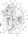
- the separating device for separating a material layer comprises a carrier device 10, on which a cutting head 40 is pivotably mounted.
- the cutting head 40 is suitable for forming a water abrasive jet that exits the cutting end 40 during machining.
- the carrier device 10 has an upper carrier plate 11a, on which a first carriage 12 is arranged to be movable in the X-direction to and fro. At the two transverse sides of the carriage 12 are first guides 13a, 13b, which predetermine an exact linear trajectory during the process. On the upper support plate 11a, a first drive 14 is further arranged, which serves for the controlled displacement of the first carriage 12.
- the first carriage 12 has a recess 15, through which the inlet-side end of the cutting head 40 protrudes. Further, the first carriage 12 is provided with second guides 16a, 16b which are transverse to the first Run guides 13a, 13b and define a precise linear trajectory for a second carriage 17. This is therefore arranged in the Y-direction movable back and forth on the first carriage 12. A mounted on the first carriage 12 second drive 18 is used for controlled displacement of the second carriage 17th
- the respective guide 13a, 13b, 16a, 16b is in the form of a linear guide with rolling elements, for. B. a recirculating ball guide, or in the form of another suitable linear guide.
- a drive 14, 18 z. B. suitable for a linear drive In the present exemplary embodiment, the first drive 14 comprises a linear axle 14a fastened to the upper support plate 11a and a drive housing 14b fastened to the first slide 12.
- the second drive 18 comprises a linear axle 18a fastened to the first carriage 12 and a drive housing 18b fastened to the second carriage 17.
- the respective drive housing 14b, 18b is linearly displaceable with respect to the linear axis 14a or 18a.
- the components 12-18 form a cross slide with a drive device.
- hinge means 50, 60 are provided, which serve for the pivotable mounting of the cutting head 40 .
- the maximum angle through which the cutting head is pivotable is typically at least 5 degrees and / or at most 20 degrees.
- the hinge means comprise a first hinge 50, which on a lower support plate 11 b of the support device 10th is held, and a second hinge 60, which is held on the second carriage 17.
- the two support plates 11a and 11b are spaced apart from each other and firmly connected to each other via side members 11c.
- the support means 10 together with the fixedly attached or pivotable parts as a whole in space, i. H. arranged to be movable in the X, Y and Z axes.
- customary drives and guides are provided (not shown in the figures).
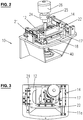
- a valve 24 for switching on and off of the cutting beam.
- the valve 24 has an inlet 25 through which water is introduced under high pressure during operation. Typically, pressures up to 6000 bar or more are generated.
- actuator 26 For switching the valve 24 is an attached thereto actuator 26.
- the coupling of the stationary high-pressure line to the inlet 25 via conventional components, such as high-pressure line spirals and hinges, which allow the pivoting of the cutting head 40 relative to the stationary high-pressure line.
- Fig. 2 also Fig. 3 shows, in the present embodiment, external displacement measuring devices 21, 22 are provided, which serve for the accurate detection of the current position of the carriage 12 and 17 and thereby allow a precise driving of the drives 14, 18 in order to accurately position the carriages 12, 17 can.
- a path measuring device 21, 22, inter alia, an optoelectronic path measuring device is suitable, in which divisions on a scale system, for. B. glass scale, optically detected and corresponding electrical Wegmesssignale be generated.
- an external displacement measuring device 21, 22 it is also conceivable to use a drive 14, 18, in which a distance measuring system is already integrated.
- Fig. 4 shows, located at the outlet end of the cutting head 40 is connected to this button 30.
- Cutting head 40 and button 30 are pivoted together, as is apparent from Fig. 5 is apparent.
- Cutting head 40 and probe 30 are thus arranged in the present embodiment that they are not pivotally relative to each other.
- the probe 30 has a passage opening 31, which is surrounded by a spherical surface 32 and through which the cutting beam passes during operation.
- the button 30 in the direction of the longitudinal axis of the cutting head 40 back and forth.
- the head 31, 32 of the button 30 is coupled via at least one displaceable shaft 34 to a (not shown in the figures) probe drive. This drive is held on the cutting head 40 and pivotable together with this.
- Fig. 6 the usual parts of the cutting head 40 for cutting by Wasserabrasivstrahls can be seen: collimation tube 41 for guiding and flow calming the water, water nozzle 42 for converting the pressure energy into kinetic energy, mixing chamber 43, in which an inlet port 44 leads to the supply of abrasive material, and focussing tube 45 to Acceleration of the abrasive material and for aligning and bundling the water-abrasive mixture.
- collimation tube 41 for guiding and flow calming the water
- water nozzle 42 for converting the pressure energy into kinetic energy
- mixing chamber 43 in which an inlet port 44 leads to the supply of abrasive material
- focussing tube 45 to Acceleration of the abrasive material and for aligning and bundling the water-abrasive mixture.
- the exact configuration of the cutting head 40 depends on the design of the separator. When pure water jet cutting, for example, mixing chamber 43 and inlet pipe 44 need not be provided.
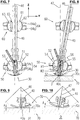
- Fig. 7 shows in more detail the embodiment of the joints 50 and 60 for the pivotable mounting of the cutting head 40 and the probe 30.
- the joints 50, 60 are substantially formed as ball joints.
- the first joint 50 has a first spherical body 51 with a spherical outer surface 52, which can slide along a spherical inner surface 53 of a first holder 54.
- the cutting head 40 with its components 41-45 and the probe drive is firmly connected to the spherical body 51.
- the first holder 54 has an upper retaining ring 54a and a lower retaining ring 54b. This is detachably connected to the upper retaining ring 54a. This configuration allows a simple replacement of the cutting head 40, since it by loosening and removing the lower retaining ring 54b down, d. H. can be removed in the direction of the negative Z axis; an expansion of the second joint 60 or other components arranged on the carrier device 10 is not absolutely necessary.
- the second hinge 60 is constructed similarly to the first hinge 50 and includes a second spherical body 61 having a spherical outer surface 62 and a second holder 64 having a spherical inner surface 63, the second holder 64 being composed of an upper retaining ring 64a and a lower retaining ring 64b.
- the cutting head 40 is fixedly connected to the first spherical body 51, while the second joint 60 of the cutting head 40 is fixedly connected to a sleeve 65 which is received in a bore in the second spherical body 61 and relative to this in the direction of Cutting head axis 46 (direction in which the cutting beam propagates) is displaceable.
- the second joint 60 is thus a ball joint with an integrated axial guide, whereby a compensation of the cutting head 40 in the direction of the cutting head axis 46 is made possible during pivoting.
- Fig. 8 is shown a possible pivoting:
- the second joint 60 is displaced in the Y direction, whereby the entire cutting head 40 is pivoted together with the probe 30 by an angle relative to the vertical 47, which corresponds to the Z-axis in the present example.
- the pivot center is given by the center 55 of the spherical surfaces 52, 53 and is thus located within the first joint 50.
- the spherical inner surface 53 of the first joint 50 rests on the surface of a sphere of radius R1 and the spherical surface 32 of the probe 30 rests on the surface of a sphere of radius R2 (see dot-dashed circle 56 in FIG Fig. 8 ).
- the radius R2 is greater than the radius R1 and chosen so that when the probe 30 is extended so far until the outlet opening 40a of the cutting head 40, from which the cutting jet emerges during the separation process, comes to lie in the through hole 31 of the probe 30 in that the pivoting center 55 coincides with the center of the sphere of radius R2.
- the geometry of the cutting head 40 is selected so that the pivot center 55 can be brought close to the surface 70a of the material layer 70.
- the minimum distance between pivot center 55 and exit opening 40a of the cutting head 40 is typically less than three times R1 and / or less than two times R1.
- Fig. 9 is the distance between the outlet opening 40a and surface 70a designated A.
- the distance A also changes. This change is usually small, but for very accurate cutting it is also compensated by the cutting head 40 is tracked in the Z-axis so that the distance A remains the same ( see. Fig. 10 ).
- FIGS. 11 to 13 a second embodiment of the first joint 50 'for supporting the cutting head 40 is shown.
- This is attached to a hinge part 51 ', which has a spherical outer surface 52'.
- the mating surface for the formation of the joint 50 ' is given by the inner surface 53', which is part of a serving as a ball socket shell body 54 '.
- This is laterally attached to a holding plate 11 'and provided at the top with a through hole 57' through which the cutting head 40 protrudes.
- the spherical inner surface 53 ' lies on the surface of a sphere of radius R1' and pivot center 55 '.
- the pivot center 55 'and the cutting point coincide.
- the pivot center 55 'and thus the cutting point can be arranged so that it lies on the workpiece surface 70a.
- a button For detecting the distance between the cutting head 40 and the workpiece surface 70a is a button, which for clarity in FIGS. 11 to 13 not shown and the like the button 30 according to Fig. 6 formed and slidably held by a stylus drive on the cutting head 40.
- the remaining components for forming a separating device, in particular the carriages 12, 17 and the second joint 60 are configured as in the first embodiment according to Fig. 1 ,
- the device During operation of the separating devices shown so far, the device generates from the drives 14, 18 longitudinal movements in the X and Y directions, which are received by the guides 13a, 13b, 16a, 16b and via the carriages 12, 17 and joints 50 and 50 '. and 60 are transferred to the cutting head 40.
- the cutting head 40 is thereby pivoted about the pivot center 55 and 55 '.
- Fig. 14 schematically shows the separation of a material layer 70 by means of a water jet 40 b, which emerges from the outlet opening 40 a of the cutting head 40.
- the button 30 is not shown.
- the cutting head axis 46 is inclined by a pivoting angle relative to the Z-axis such that a cutting edge 70c on the useful part, which is perpendicular to the surface 70a of the material layer 70, is formed during cutting.
- the other cutting edge 70b on the waste part is bevelled more than usual by the tilting angle, which does not matter because this part is no longer used.
- Fig. 14 is just an example. Depending on the application, the cutting edge 70c may also be laid differently. Furthermore, since the cutting head 40 is pivotable in an arbitrary direction, in addition to the angular error, the shape error can also be at least greatly reduced.
- the controller In order to determine the pivot angle about which the cutting head 40 is to be pivoted, the controller has a computer which is provided with a suitable program. This is z. B. configured so that it calculates the expected angular and shape errors based on a mathematical model and determines the tilt angle to correct these errors. The calculation is based on various parameters, which the user defines and which u. a. characterize the material layer to be processed, such as the type and thickness of the material.
- the pivot center 55 is spaced from the surface 70a.
- the X, Y and Z axes are tracked. This can be the above mentioned Program be set up so that it also calculates the corresponding correction in the axes in addition to the swivel angle, and thus control signals are generated by the controller, which cause a corresponding tracking of the cutting head 40.
- a calibration may be performed to determine the correction parameters that define tracking in the X and Y axes to cut a particular layer of material.
- a specimen of the material layer is cut by the pivoting head 40 is tilted about the maximum pivoting angle and pivoted about the Z-axis, so that the cutting jet cuts out a cone from the specimen. From the dimensions of this cone, the correction parameters for tracking in the X and Y axes can be determined. These parameters are z. B. entered by the user in the computer of the controller, so that they can calculate and initiate the respective required tracking when cutting the actual material layer.
- a correction in the Z-axis z. B. also be necessary if the material layer has an uneven surface and / or not flat rests.
- the coupled to the button 30 button drive is also force-driven to move the button 30 with a specific, predetermined force.
- the preloaded mode is u. a. used in the processing of a thin layer of material, for. B. a sheet having a thickness in the range of 1 mm.
- the biased mode may be advantageous in that the contact force generated by the button 30 prevents any oscillation of the workpiece and thus the cutting point is precisely positioned at the desired location on the workpiece surface.
- starting torque For example, a certain moment is required to rotate the stationary spherical bodies 51, 61 of the joints 50, 60.
- starting torque For example, a certain moment is required to rotate the stationary spherical bodies 51, 61 of the joints 50, 60.
- the control is in a continuation formed so that during the cutting operation of the swivel head 40 is moved continuously. For example, when the cutting head 40 is cut along a straight line extending in the X direction, it is pivoted back and forth in that direction so as to keep moving.
- a probe for detecting the distance between the cutting head and the surface of the material layer which is arranged externally to the cutting head and thus is not pivotable together with this.
- the button is coupled to its displacement to a button drive. This allows, inter alia, the button with a to move to a specific, definable force.
Abstract
Die Trennvorrichtung zum Trennen einer Materialschicht (70) mittels eines Schneidstrahls umfass einen Schneidkopf (40), aus welchem beim Trennvorgang der Schneidstrahl austritt, ein Gelenk (50) mit sphärischen Flächen (52, 53) zur schwenkbaren Anordnung des Schneidkopfes (40) und eine Antriebseinrichtung zum Schwenken des Schneidkopfes (40). Gemäss einem ersten Aspekt ist der Schneidkopf um ein Schwenkzentrum (55) schwenkbar, das von den sphärischen Flächen (52, 53) umgeben ist, so dass es innerhalb des Gelenkes (50) angeordnet ist. Gemäss einem zweiten Aspekt umfasst die Trennvorrichtung einen Taster (30) zum Erfassen des Abstandes zwischen Schneidkopf (40) und Oberfläche (70a) der Materialschicht (70).The separating device for separating a material layer (70) by means of a cutting jet comprises a cutting head (40) from which emerges during the cutting process of the cutting beam, a joint (50) with spherical surfaces (52, 53) for pivotally mounting the cutting head (40) and a Drive device for pivoting the cutting head (40). According to a first aspect, the cutting head is pivotable about a pivot center (55) surrounded by the spherical surfaces (52, 53) so as to be disposed within the hinge (50). According to a second aspect, the separating device comprises a probe (30) for detecting the distance between the cutting head (40) and the surface (70a) of the material layer (70).
Description
Die vorliegende Erfindung bezieht sich auf eine Trennvorrichtung zum Trennen einer Materialschicht mittels eines Schneidstrahls.The present invention relates to a separating device for separating a material layer by means of a cutting jet.
Die Energie, welche der Schneidstrahl einer derartigen Trennvorrichtung erzeugt, wird dazu benutzt, eine Materialschicht entlang einer Kontur zu trennen. Als Schneidstrahl eignet sich beispielsweise ein Flüssigkeitsstrahl, der mit hoher Geschwindigkeit auf die Materialoberfläche trifft. Durchdringt der Flüssigkeitsstrahl das Material, so kommt es zu einem Energieverlust in Tiefenrichtung der Materialschicht, wodurch ein durch zwei Schnittkanten begrenzter Schnittspalt entsteht.The energy generated by the cutting beam of such a separator is used to separate a layer of material along a contour. As a cutting jet, for example, a liquid jet is suitable, which hits the material surface at high speed. If the liquid jet penetrates the material, there is an energy loss in the depth direction of the material layer, resulting in a kerf limited by two cut edges.
Ist die Richtung, in welcher sich der Schneidstrahl ausbreitet, - im Folgenden auch "Schneidkopfachse" genannt - senkrecht zur Oberfläche der Materialschicht ausgerichtet, so werden in der Regel die Schnittkanten nur bei einer bestimmten Vorschubgeschwindigkeit des Schneidkopfes parallel zueinander verlaufen. Diese Situation ist in
Bei zu geringer Vorschubgeschwindigkeit wird der Schnittspalt an der Unterkante des Werkstückes 70 breiter (vgl.
Ohne weitere Massnahmen muss die Vorschubgeschwindigkeit relativ gering gewählt werden, um den Winkelfehler vermeiden und somit Werkstücke mit zufriedenstellender Qualität schneiden zu können. Eine rationelle Bearbeitung ist dadurch erschwert.Without further measures, the feed rate must be relatively low in order to avoid the angular error and thus to be able to cut workpieces of satisfactory quality. A rational processing is made more difficult.
Nebst Winkelfehlern können auch Formfehler auftreten: Wird die Richtung des Schneidkopfes geändert, um z. B. eine Ecke zu schneiden, so kann es aufgrund des Nachlaufes des Schneidstrahls (sogenannter "jet lag") zu Auswaschungen und somit zu Abweichungen von der gewünschten Form kommen.In addition to angular errors can also form errors occur: If the direction of the cutting head changed to z. B. to cut a corner, it may be due to the trailing of the cutting jet (so-called "jet lag") to washouts and thus deviations from the desired shape.
Das Problem, Schnittkanten mit zufriedenstellender Qualität zu erzeugen, stellt sich nicht nur beim Schneiden mittels Flüssigkeitsstrahl wie reinem oder abrasiven Wasserstrahlschneiden, sondern auch bei anderen Trennarten mittels Schneidstrahl, z. B. Laserschneiden, Plasmaschneiden oder dergleichen.The problem of producing cutting edges of satisfactory quality, not only when cutting by means of liquid jet as pure or abrasive water jet cutting, but also in other types of separation by means of cutting jet, z. As laser cutting, plasma cutting or the like.
Aus der
Es sind auch fünfachsige Trennvorrichtungen bekannt, welche nebst den üblichen drei Achsen zum räumlichen Verschieben des Schneidkopfes zwei weitere Achsen aufweisen, um den Schneidkopf und somit den Schneidstrahl im Raum ausrichten zu können (siehe z. B.
Es ist eine Aufgabe der vorliegenden Erfindung, eine Trennvorrichtung anzugeben, die mittels eines Schneidstrahls ein präzises und rationelles Trennen einer Materialschicht ermöglicht.It is an object of the present invention to provide a separation device which enables a precise and efficient separation of a material layer by means of a cutting jet.
Eine Trennvorrichtung, die diese Aufgabe löst, ist im Anspruch 1 oder 4 angegeben. Die weiteren Ansprüche geben bevorzugte Ausführungen sowie eine Verwendung der Trennvorrichtung an.A separating device which achieves this object is specified in
Die erfindungsgemässe Trennvorrichtung umfasst ein Gelenk mit sphärischen Flächen zur schwenkbaren Anordnung des Schneidkopfes und eine Antriebseinrichtung zum Schwenken des Schneidkopfes.The separating device according to the invention comprises a joint with spherical surfaces for the pivotable arrangement of the cutting head and a drive device for pivoting the cutting head.
Gemäss einem ersten Aspekt der Erfindung ist der Schneidkopf um ein Schwenkzentrum schwenkbar, welches von den sphärischen Flächen umgeben ist.According to a first aspect of the invention, the cutting head is pivotable about a pivoting center which is surrounded by the spherical surfaces.
Gemäss einem zweiten Aspekt der Erfindung umfasst die Trennvorrichtung einen Taster zum Erfassen des Abstandes zwischen Schneidkopf und Oberfläche der Materialschicht.According to a second aspect of the invention, the separating device comprises a probe for detecting the distance between the cutting head and the surface of the material layer.
Die erfindungsgemässe Trennvorrichtung erlaubt es, eine Materialschicht mittels des Schneidstrahls präzise und rationell zu trennen.The separating device according to the invention makes it possible to precisely and efficiently separate a material layer by means of the cutting jet.
Weitere Konstruktionsmerkmale und deren Vorteile sind aus folgender Beschreibung und Zeichnungen von Ausführungsbeispielen ersichtlich. Es zeigen
-
Fig. 1 eine perspektivische Ansicht einer erfindungsgemässen Trennvorrichtung; -
Fig. 2 die Vorrichtung gemässFig. 1 mit weiteren Komponenten zur Wasserzufuhr sowie zur Wegmessung; -
Fig. 3 die Vorrichtung gemässFig. 2 in einer Draufsicht; -
Fig. 4 den in Gelenken gelagerte Schneidkopf der Vorrichtung gemässFig. 1 in einer Seitenansicht; -
Fig. 5 eine perspektivische Ansicht des unteren Teils des Schneidkopfes gemässFig. 4 im geschwenkten Zustand; -
Fig. 6 einen Längsschnitt des Schneidkopfes gemässFig. 5 zusammen mit einem Werkstück; -
Fig. 7 einen Längsschnitt des Schneidkopfes gemässFig. 4 ; -
Fig. 8 einen Längsschnitt des Schneidkopfes gemässFig. 4 im geschwenkten Zustand; -
Fig. 9 eine Detailansicht ausFig. 7 zusammen mit einem Werkstück; -
Fig. 10 die Detailansicht gemässFig. 9 im geschwenkten Zustand; -
Fig. 11 eine perspektivische Ansicht einer zweiten Ausführungsform der Schneidkopflagerung für eine erfindungsgemässen Trennvorrichtung; -
Fig. 12 einen Längsschnitt des Schneidkopfes der Trennvorrichtung gemässFig. 9 im aufgerichteten Zustand; -
Fig. 13 den Längsschnitt des Schneidkopfes gemässFig. 12 im geschwenkten Zustand; -
Fig. 14 eine geschnittene Seitenansicht einer Materialschicht, welche mit der Vorrichtung gemässFig. 1 getrennt wird; und -
Fig. 15a-15c schematisch die Verläufe eines Wasserstrahls beim Durchtrennen einer Materialschicht bei drei verschiedenen Vorschubgeschwindigkeiten eines Schneidkopfes, wenn dieser aufgerichtet ist.
-
Fig. 1 a perspective view of an inventive separation device; -
Fig. 2 the device according toFig. 1 with other components for water supply and distance measurement; -
Fig. 3 the device according toFig. 2 in a plan view; -
Fig. 4 the mounted in joints cutting head of the device according toFig. 1 in a side view; -
Fig. 5 a perspective view of the lower part of the cutting head according toFig. 4 in the tilted state; -
Fig. 6 a longitudinal section of the cutting head according toFig. 5 together with a workpiece; -
Fig. 7 a longitudinal section of the cutting head according toFig. 4 ; -
Fig. 8 a longitudinal section of the cutting head according toFig. 4 in the tilted state; -
Fig. 9 a detailed viewFig. 7 together with a workpiece; -
Fig. 10 the detailed view according toFig. 9 in the tilted state; -
Fig. 11 a perspective view of a second embodiment of the cutting head storage for an inventive separation device; -
Fig. 12 a longitudinal section of the cutting head of the separator according toFig. 9 in the erected state; -
Fig. 13 the longitudinal section of the cutting head according toFig. 12 in the tilted state; -
Fig. 14 a sectional side view of a material layer, which with the device according toFig. 1 is disconnected; and -
Fig. 15a-15c schematically the progressions of a water jet when cutting a layer of material at three different feed speeds of a cutting head, when this is erected.
Wie aus
Die Trägereinrichtung 10 weist eine obere Trägerplatte 11a auf, auf welcher ein erster Schlitten 12 in X-Richtung hin und her verfahrbar angeordnet ist. An den beiden Querseiten des Schlittens 12 befinden sich erste Führungen 13a, 13b, welche beim Verfahren eine genaue lineare Bewegungsbahn vorgeben. Auf der oberen Trägerplatte 11a ist weiter ein erster Antrieb 14 angeordnet, der zum gesteuerten Verschieben des ersten Schlittens 12 dient.The
Der erste Schlitten 12 weist eine Ausnehmung 15 auf, durch welche das einlassseitige Ende des Schneidkopfes 40 hindurchragt. Weiter ist der erste Schlitten 12 mit zweiten Führungen 16a, 16b versehen, die quer zu den ersten Führungen 13a, 13b verlaufen und eine genaue lineare Bewegungsbahn für einen zweiten Schlitten 17 definieren. Dieser ist demnach in Y-Richtung hin und her verfahrbar am ersten Schlitten 12 angeordnet. Ein am ersten Schlitten 12 angebrachter zweiter Antrieb 18 dient zum gesteuerten Verschieben des zweiten Schlittens 17.The
Die jeweilige Führung 13a, 13b, 16a, 16b ist beispielsweise in Form einer Linearführung mit Wälzkörpern, z. B. einer Kugelumlaufführung, oder in Form einer anderen geeigneten Linearführung ausgebildet. Als Antrieb 14, 18 ist z. B. ein Linearantrieb geeignet. Im vorliegenden Ausführungsbeispiel umfasst der erste Antrieb 14 eine an der oberen Trägerplatte 11a befestigte Linearachse 14a sowie ein am ersten Schlitten 12 befestigtes Antriebsgehäuse 14b. Entsprechend umfasst der zweite Antrieb 18 eine am ersten Schlitten 12 befestigte Linearachse 18a sowie ein am zweiten Schlitten 17 befestigtes Antriebsgehäuse 18b. Das jeweilige Antriebsgehäuse 14b, 18b ist in Bezug auf die Linearachse 14a bzw. 18a linear verschiebbar.The
Insgesamt bilden die Komponenten 12-18 einen Kreuzschlitten mit einer Antriebseinrichtung.Overall, the components 12-18 form a cross slide with a drive device.
Um beim Schneiden den Schneidstrahl aus der Ausgangslage, welche hier der Z-Achse entspricht, in X-Richtung, Y-Richtung oder in eine beliebige andere Richtung neigen zu können, sind Gelenkmittel 50, 60 vorgesehen, welche zum schwenkbaren Lagern des Schneidkopfes 40 dienen. Der maximale Winkel, um welchen der Schneidkopf schwenkbar ist, beträgt typischerweise mindestens 5 Grad und/oder höchstens 20 Grad.In order to be able to tilt the cutting beam from the starting position, which here corresponds to the Z-axis, in the X-direction, Y-direction or in any other direction during cutting, hinge means 50, 60 are provided, which serve for the pivotable mounting of the cutting
Die Gelenkmittel umfassen ein erstes Gelenk 50, welches an einer unteren Trägerplatte 11b der Trägereinrichtung 10 gehalten ist, und ein zweites Gelenk 60, welches am zweiten Schlitten 17 gehalten ist. Die beiden Trägerplatten 11a und 11b sind beabstandet zueinander angeordnet und über Seitenelemente 11c miteinander fest verbunden.The hinge means comprise a
Die Trägereinrichtung 10 ist zusammen mit den daran fest angebrachten bzw. schwenkbaren Teilen als Ganzes im Raum, d. h. in der X-, Y- und Z-Achse verfahrbar angeordnet. Dazu sind übliche Antriebe und Führungen vorgesehen (in den Figuren nicht dargestellt).The support means 10 together with the fixedly attached or pivotable parts as a whole in space, i. H. arranged to be movable in the X, Y and Z axes. For this purpose, customary drives and guides are provided (not shown in the figures).
Wie
Wie nebst
Wie
Wie in
In
Das erste Gelenk 50 weist einen ersten Kugelkörper 51 auf mit einer sphärischen Aussenfläche 52, die entlang einer sphärischen Innenfläche 53 einer ersten Halterung 54 gleiten kann. Der Schneidkopf 40 mit seinen Komponenten 41-45 und dem Tasterantrieb ist fest mit dem Kugelkörper 51 verbunden.The first joint 50 has a first
Die erste Halterung 54 weist einen oberen Haltering 54a sowie einen unteren Haltering 54b auf. Dieser ist lösbar mit dem oberen Haltering 54a verbunden. Diese Ausgestaltung erlaubt ein einfaches Auswechseln des Schneidkopfes 40, da er durch Lösen und Entfernen des unteren Halteringes 54b nach unten, d. h. in Richtung der negativen Z-Achse entfernt werden kann; ein Ausbau des zweiten Gelenkes 60 oder anderer auf der Trägereinrichtung 10 angeordneten Komponenten ist nicht unbedingt erforderlich.The
Das zweite Gelenk 60 ist ähnlich wie das erste Gelenk 50 aufgebaut und umfasst einen zweiten Kugelkörper 61 mit sphärischer Aussenfläche 62 und eine zweite Halterung 64 mit sphärischer Innenfläche 63, wobei die zweite Halterung 64 sich aus einem oberen Haltering 64a und einem unteren Haltering 64b zusammensetzt. Beim ersten Gelenk 50 ist jedoch der Schneidkopf 40 fest mit dem ersten Kugelkörper 51 verbunden, während beim zweiten Gelenk 60 der Schneidkopf 40 fest mit einer Büchse 65 verbunden ist, die in einer Bohrung im zweiten Kugelkörper 61 aufgenommen ist und relativ zum diesem in Richtung der Schneidkopfachse 46 (Richtung, in welcher sich der Schneidstrahl ausbreitet) verschiebbar ist.The
Das zweite Gelenk 60 ist demnach ein Kugelgelenk mit einer integrierten axialen Führung, wodurch beim Schwenken ein Ausgleich des Schneidkopfes 40 in Richtung der Schneidkopfachse 46 ermöglicht wird. In
Die sphärische Innenfläche 53 des ersten Gelenkes 50 liegt auf der Oberfläche einer Kugel mit Radius R1 und die sphärische Fläche 32 des Tasters 30 liegt auf der Oberfläche einer Kugel mit Radius R2 (vgl. punktgestrichelte Kreislinie 56 in
Die Geometrie des Schneidkopfes 40 ist so gewählt, dass das Schwenkzentrum 55 nahe an die Oberfläche 70a der Materialschicht 70 gebracht werden kann. Der minimale Abstand zwischen Schwenkzentrum 55 und Austrittsöffnung 40a des Schneidkopfes 40 ist typischerweise kleiner als das Dreifache von R1 und/oder kleiner als das Zweifache von R1.The geometry of the cutting
Da das Schwenkzentrum 55 beabstandet zur Oberfläche 70a des Werkstückes 70 angeordnet ist, verschiebt sich bei einer Schwenkung des Schneidkopfes 40 die Position des Schneidpunktes (Schnittpunkt der Schneidkopfachse 46 mit der Materialoberfläche 70a). Dies ist aus den
In
In den
Die sphärische Innenfläche 53' liegt auf der Oberfläche einer Kugel mit Radius R1' und Schwenkzentrum 55'. Im vorliegenden Ausführungsbeispiel fallen das Schwenkzentrum 55' und der Schneidpunkt zusammen. Beim Trennvorgang kann das Schwenkzentrum 55' und somit der Schneidpunkt so angeordnet werden, dass es bzw. er auf der Werkstücksoberfläche 70a liegt.The spherical inner surface 53 'lies on the surface of a sphere of radius R1' and pivot center 55 '. In the present embodiment, the pivot center 55 'and the cutting point coincide. During the separation process, the pivot center 55 'and thus the cutting point can be arranged so that it lies on the
Zur Erfassung des Abstandes zwischen Schneidkopf 40 und Werkstücksoberfläche 70a dient ein Taster, der zur besseren Übersicht in
Beim Betrieb der soweit dargestellten Trennvorrichtungen erzeugt die Einrichtung aus den Antrieben 14, 18 Längsbewegungen in X- und Y-Richtung, welche von den Führungen 13a, 13b, 16a, 16b aufgenommen und über die Schlitten 12, 17 und Gelenke 50 bzw. 50' und 60 auf den Schneidkopf 40 übertragen werden. Der Schneidkopf 40 wird dadurch um das Schwenkzentrum 55 bzw. 55' geschwenkt.During operation of the separating devices shown so far, the device generates from the
Die verschiedenen Bewegungen, wie das Verfahren der Trägereinrichtung 10 als Ganzes im Raum, die Schwenkung des Schneidkopfes 40 relativ zur Trägereinrichtung 10 um das Schwenkzentrum 55, 55' und das Verfahren des Tasters 30 in Richtung 33, erfolgen gesteuert mittels einer (in den Figuren nicht dargestellten) Steuerung, z. B. einer CNC-Steuerung.The various movements, such as the method of the
Aufgrund der Schwenkbarkeit des Schneidkopfes 40 können Form- und Winkelfehler behoben oder zumindest reduziert werden. Das Beispiel in
Im vorliegenden Beispiel ist die Schneidkopfachse 46 so um einen Schwenkwinkel gegenüber der Z-Achse geneigt, dass beim Schneiden eine Schnittkante 70c am Nutzteil entsteht, die senkrecht zur Oberfläche 70a der Materialschicht 70 steht. Die andere Schnittkante 70b am Abfallteil ist um den Schwenkwinkel mehr als üblich abgeschrägt, was aber keine Rolle spielt, da dieses Teil nicht weiter verwendet wird.In the present example, the cutting
Zur Festlegung des Schwenkwinkels, um den der Schneidkopf 40 zu schwenken ist, weist die Steuerung einen Computer auf, welcher mit einem geeigneten Programm versehen ist. Dieses ist z. B. so ausgestaltet, dass es anhand eines mathematischen Modells die zu erwartenden Winkel- und Formfehler berechnet und den Schwenkwinkel bestimmt, um diese Fehler zu korrigieren. Die Berechnung erfolgt dabei ausgehend von verschiedenen Parametern, welche der Benutzer festlegt und welche u. a. die zu bearbeitende Materialschicht wie Art und Dicke des Materials charakterisieren.In order to determine the pivot angle about which the cutting
Bei der Lagerung gemäss
Zur Bestimmung der Korrekturparameter, welche die Nachführung in der X- und Y-Achse definieren, um eine bestimmte Materialschicht zu schneiden, kann beispielsweise eine Eichung durchgeführt werden. Dazu wird ein Probestück der Materialschicht geschnitten, indem der Schwenkkopf 40, um den maximalen Schwenkwinkel schräggestellt und um die Z-Achse herum geschwenkt wird, so dass der Schneidstrahl einen Konus aus dem Probestück herausschneidet. Aus den Abmessungen dieses Konus lassen sich die Korrekturparameter für die Nachführung in der X- und Y-Achse bestimmen. Diese Parameter werden z. B. vom Benutzer in den Computer der Steuerung eingegeben, so dass diese beim Schneiden der eigentlichen Materialschicht die jeweils erforderliche Nachführung berechnen und einleiten kann.For example, a calibration may be performed to determine the correction parameters that define tracking in the X and Y axes to cut a particular layer of material. For this purpose, a specimen of the material layer is cut by the pivoting
Nebst dem Schwenken kann eine Korrektur in der Z-Achse z. B. auch dann nötig sein, wenn die Materialschicht eine unebene Oberfläche aufweist und/oder nicht plan aufliegt. Mittels des Tasters 30 können Abweichungen in vertikaler Richtung erfasst und kompensiert werden. Der an den Taster 30 gekoppelte Tasterantrieb ist auch kraftgesteuert antreibbar, um den Taster 30 mit einer bestimmten, vorgebbaren Kraft zu verschieben.In addition to the panning, a correction in the Z-axis z. B. also be necessary if the material layer has an uneven surface and / or not flat rests. By means of the
Der Taster 30 ist wahlweise getaktet, kontinuierlich oder vorgespannt einsetzbar:
- Beim getakteten Modus wird in vorbestimmten Zeitintervallen der
Taster 30 auf dieMaterialoberfläche 70a aufgesetzt zur aktuellen Erfassung des Abstandes, damit, falls erforderlich, eine Korrektur des Schneidkopfes 40 vorgenommen werden kann. - Beim kontinuierlichen Modus bleibt der
Taster 30 während des kompletten Schneidvorganges auf der Materialoberfläche 70a, wobei auftretende Abweichungen an die Steuerung gemeldet werden, die eine entsprechende Korrektur bewirkt. Dabei bleibt derTaster 30 aufgrund seiner sphärischen Fläche 32mit der Materialoberfläche 70a immerzu in Kontakt, auch wenn der Schneidkopf 40 geschwenkt wird. - Vorgespannter Modus bedeutet, dass der
Taster 30 mit einer vordefinierten Kraft auf das Material wirkt, um so einen konstanten Abstand zu gewährleisten.
- In the clocked mode, the
button 30 is placed on thematerial surface 70a for the current detection of the distance at predetermined time intervals, so that, if necessary, a correction of the cuttinghead 40 can be made. - In the continuous mode, the key 30 remains on the
material surface 70a during the entire cutting process, and any deviations that occur are reported to the controller, which causes a corresponding correction. In this case, theprobe 30 always remains in contact with thematerial surface 70a due to itsspherical surface 32, even when the cuttinghead 40 is pivoted. - Prestressed mode means that the
button 30 acts on the material with a predefined force so as to ensure a constant distance.
Ein möglicher Ablauf bei der Verwendung des Tasters 30 im getakteten oder kontinuierlichen Modus ist wie folgt:
- Referenzierung des Tasters:
Der Schneidkopf 40 befindet sich in der Null-Grad-Auslenkung, d. h. dieSchneidkopfachse 46 verläuft senkrecht zur Materialoberfläche 70a, wobei diese vom Taster 30 kontaktiert wird. Der aktuelle Abstand zwischen der Austrittsöffnung 40a des Schneidkopfes 40 und der Tasteroberfläche 32, die tangential ander Materialoberfläche 70a anliegt, wird erfasst und definiert den Ist-Abstand.
Der Schneidkopf 40 wird in den Soll-Abstand A gebracht, welcher der Steuerung bekannt ist und/oder vorgängig eingegeben wurde.- Während dem Abarbeiten des Schneidprogramms wird der Abstand zwischen Austrittsöffnung 40a und Materialoberfläche 70a (getaktet oder kontinuierlich) bestimmt. Entspricht der Abstand nicht dem Soll-Abstand A, so wird der Schneidkopf 40 entsprechend nachgeführt, hier durch Verschiebung in der Z-Achse.
Werden Schneidkopf 40und Taster 30 geschwenkt, so entfernt sich beim ersten Ausführungsbeispiel gemässFig. 1 der Schneidpunkt von der Sollkontur, entlang welcherdas Werkstückes 70 getrennt werden soll (vgl. Distanz D inFig. 10 ). Die Steuerung liefert Steuersignale, welche einen Ausgleich der Verschiebung D von der Sollkontur bewirken. Die Steuersignale sind wie weiter oben erläutert z. B. mit Hilfe eines mathematischen Modells berechenbar. Im Weiteren sind mit der Steuerung ebenfalls Steuersignale erzeugbar, welche bewirken, dass der Abstand A zwischen Austrittsöffnung 40a und Materialoberfläche 70a konstant bleibt (vgl. Abstand A inFig. 9 und 10 ).
- Referencing the button:
- The cutting
head 40 is in the zero-degree deflection, ie the cuttinghead axis 46 is perpendicular to thematerial surface 70a, which is contacted by thebutton 30. The actual distance between theexit opening 40a of the cuttinghead 40 and theprobe surface 32, which bears tangentially on thematerial surface 70a, is detected and defines the actual distance.
- The cutting
- The cutting
head 40 is brought into the desired distance A, which is the controller known and / or previously entered. - During execution of the cutting program, the distance between exit opening 40a and
material surface 70a (clocked or continuous) is determined. If the distance does not correspond to the nominal distance A, so the cuttinghead 40 is tracked accordingly, here by shifting in the Z-axis. - If the cutting
head 40 and the key 30 are pivoted, it is removed according to the first exemplary embodimentFig. 1 the cutting point of the desired contour, along which theworkpiece 70 is to be separated (see Distance D inFig. 10 ). The control supplies control signals which bring about a compensation of the displacement D from the desired contour. The control signals are as explained above, for. B. can be calculated using a mathematical model. In addition, control signals can also be generated with the control, which effect that the distance A between theoutlet opening 40a and thematerial surface 70a remains constant (cf., distance A in FIGFIGS. 9 and 10 ).
Ein möglicher Ablauf bei der Verwendung des Tasters 30 im vorgespannten Modus ist wie folgt:
- Die
Referenzierung des Tasters 30 erfolgt wie oben beim getakteten bzw. kontinuierlichen Modus beschrieben. - Im Schneidbetrieb wirkt der
Taster 30 mit einer vorbestimmten Kraft auf das zu bearbeitendeMaterial 70. Damit der Abstand A zwischen Materialoberfläche 70a und der Austrittsöffnung 40a konstant bleibt, wird der Schneidkopf 40 wie oben beschrieben in der Achse nachgeführt. - Die Steuerung ist so eingerichtet, dass der Benutzer auswählen kann,
ob der Taster 30 permanent oder nur in gewünschten Passagen (z. B. auf langen Geraden) mit der vorgewählten Kraft aufdas Material 70 drückt. Im letzteren Fall wird der Taster 30 in den übrigen Passagen, insbesondere in engen, die z. B. bei vielen Richtungsänderungen auf engem Raum auftreten, im getakteten oder kontinuierlichen Modus oder gar nicht eingesetzt wird.
- The referencing of the
button 30 is carried out as described above in the clocked or continuous mode. - In the cutting operation of the
probe 30 acts with a predetermined force on the material to be processed 70. So that the distance A between thematerial surface 70a and the outlet opening 40a remains constant, the cuttinghead 40 is tracked as described above in the axis. - The controller is arranged so that the user can select whether the
button 30 presses the material 70 permanently or only in desired passages (eg on long straight lines) with the preselected force. In the latter case, thebutton 30 in the other passages, especially in narrow, the z. B. in many Changes in direction occur in a small space, in clocked or continuous mode or not used at all.
Der vorgespannte Modus ist u. a. bei der Bearbeitung einer dünnen Materialschicht einsetzbar, z. B. eines Bleches mit einer Dicke im Bereich von 1 mm. Durch das Andrücken des Tasters an die Materialoberfläche wird erreicht, dass die Materialschicht plan aufliegt. Auch bei anderen Werkstücken kann der vorgespannte Modus vorteilhaft sein, indem die durch den Taster 30 erzeugte Anpresskraft ein etwaiges Schwingen des Werkstückes verhindert und so der Schneidpunkt präzise an der gewünschten Stelle auf der Werkstücksoberfläche positionierbar ist.The preloaded mode is u. a. used in the processing of a thin layer of material, for. B. a sheet having a thickness in the range of 1 mm. By pressing the button on the material surface is achieved that the material layer rests flat. In other workpieces, the biased mode may be advantageous in that the contact force generated by the
Damit der Schneidkopf 40 beim Anfahren aus dem Stillstand in Bewegung gerät, ist ein gewisses Moment zu überwinden ("Losfahrmoment"). Beispielsweise wird ein gewisses Moment benötigt, um die ruhenden Kugelkörper 51, 61 der Gelenke 50, 60 zu drehen. Zur Vermeidung derartiger Losfahrmomente ist die Steuerung in einer Weiterführung so ausgebildet, dass beim Schneidvorgang der Schwenkkopf 40 laufend bewegt wird. Beispielsweise wird der Schwenkkopf 40, wenn entlang einer in X-Richtung verlaufenden geraden Linie geschnitten wird, in dieser Richtung hin und her geschwenkt, so dass er ständig in Bewegung bleibt.In order for the cutting
Soweit nicht schon erwähnt, haben die hier beschriebene Trennvorrichtungen und die damit verbundenen Möglichkeiten zur Kompensation des Winkel- und Formfehlers mannigfache Vorteile:
- Es kann eine höhere Vorschubgeschwindigkeit gewählt werden, ohne dass dabei die Qualität der Schnittkanten leidet. Die Bearbeitung wird dadurch rationeller.
- Der "taper" an den Schnittkanten kann eliminiert werden, so dass eine aufwendige Nachbearbeitung entfällt.
- Werkstücke können sehr präzise hergestellt werden. Selbst Werkstücke mit besonders grosser Dicke und/oder mit komplizierter Kontur sind mit einer hohen Genauigkeit in Bezug auf die Kontur sowie auf die gewünschte Abmessung herstellbar.
- Innenecken lassen sich mit einer deutlich höheren Qualität herstellen, als dies mit den üblichen Trennvorrichtungen möglich ist.
- A higher feed rate can be selected without sacrificing the quality of the cut edges. The processing becomes more efficient.
- The "taper" at the cutting edges can be eliminated, eliminating the need for elaborate post-processing.
- Workpieces can be produced very precisely. Even workpieces with a particularly large thickness and / or with a complicated contour can be produced with a high accuracy with respect to the contour and to the desired dimension.
- Internal corners can be produced with a significantly higher quality than is possible with the usual separation devices.
Aus der vorangehenden Beschreibung sind dem Fachmann zahlreiche Abwandlungen zugänglich, ohne den Schutzbereich der Erfindung zu verlassen, der durch die Ansprüche definiert ist.From the foregoing description, numerous modifications will be apparent to those skilled in the art without departing from the scope of the invention, which is defined by the claims.
So können die hier beschriebenen Massnahmen für diverse Arten von Trennen mittels Schneidstrahl angewendet werden, insbesondere Schneiden mittels Flüssigkeit wie Reinwasserschneiden oder Abrasivschneiden, Laserschneiden, Plasmaschneiden, etc.Thus, the measures described here for various types of cutting by means of cutting jet can be applied, in particular cutting by means of liquid such as pure water cutting or abrasive cutting, laser cutting, plasma cutting, etc.
Je nach Anwendungszweck und den zu erzielenden Genauigkeiten ist es auch denkbar, die Trennvorrichtung gemäss dem ersten Ausführungsbeispiel in
Weiter ist es denkbar, bei den beiden Ausführungsbeispielen gemäss
Claims (18)
einen Schneidkopf (40), aus welchem beim Trennvorgang der Schneidstrahl (40b) austritt,
ein Gelenk (50) mit sphärischen Flächen (52, 53) zur schwenkbaren Anordnung des Schneidkopfes (40) um ein Schwenkzentrum (55), welches von den sphärischen Flächen (52, 53) umgeben ist, so dass das Schwenkzentrum (55) innerhalb des Gelenkes (50) angeordnet ist, und
eine Antriebseinrichtung (14, 18) zum Schwenken des Schneidkopfes (40).Separating device for separating a material layer (70) by means of a cutting jet (40b) comprising
a cutting head (40) from which the cutting jet (40b) emerges during the separation process,
a pivot (50) having spherical surfaces (52, 53) for pivotally mounting the cutting head (40) about a pivot center (55) surrounded by the spherical surfaces (52, 53) such that the pivot center (55) is within the pivotal center (55) Joint (50) is arranged, and
a drive means (14, 18) for pivoting the cutting head (40).
einen Schneidkopf (40), aus welchem beim Trennvorgang der Schneidstrahl (40b) austritt,
ein Gelenk (50, 50') mit sphärischen Flächen (52, 53; 52,' 53') zur schwenkbaren Anordnung des Schneidkopfes (40),
eine Antriebseinrichtung (14, 18) zum Schwenken des Schneidkopfes (40), und
einen Taster (30) zum Erfassen des Abstandes zwischen Schneidkopf (40) und Oberfläche (70a) der Materialschicht (70).Separating device for separating a material layer (70) by means of a cutting jet (40b) comprising
a cutting head (40) from which the cutting jet (40b) emerges during the separation process,
a joint (50, 50 ') with spherical surfaces (52, 53, 52,' 53 ') for pivotally mounting the cutting head (40),
a drive device (14, 18) for pivoting the cutting head (40), and
a probe (30) for detecting the distance between the cutting head (40) and surface (70a) of the material layer (70).
Applications Claiming Priority (2)
| Application Number | Priority Date | Filing Date | Title |
|---|---|---|---|
| CH01938/09A CH702474A1 (en) | 2009-12-17 | 2009-12-17 | Separator for separating a material layer by means of a cutting beam. |
| EP10405235.2A EP2335856B1 (en) | 2009-12-17 | 2010-12-14 | Device for separating a part of material using a cutting beam and a cutting head having an articulation |
Related Parent Applications (2)
| Application Number | Title | Priority Date | Filing Date |
|---|---|---|---|
| EP10405235.2A Division EP2335856B1 (en) | 2009-12-17 | 2010-12-14 | Device for separating a part of material using a cutting beam and a cutting head having an articulation |
| EP10405235.2A Division-Into EP2335856B1 (en) | 2009-12-17 | 2010-12-14 | Device for separating a part of material using a cutting beam and a cutting head having an articulation |
Publications (2)
| Publication Number | Publication Date |
|---|---|
| EP3170603A1 true EP3170603A1 (en) | 2017-05-24 |
| EP3170603B1 EP3170603B1 (en) | 2019-02-13 |
Family
ID=42026261
Family Applications (2)
| Application Number | Title | Priority Date | Filing Date |
|---|---|---|---|
| EP10405235.2A Not-in-force EP2335856B1 (en) | 2009-12-17 | 2010-12-14 | Device for separating a part of material using a cutting beam and a cutting head having an articulation |
| EP16201745.3A Not-in-force EP3170603B1 (en) | 2009-12-17 | 2010-12-14 | Separating device for separating a material layer by means of a cutting jet using an articulated cutting head with a touch contactor |
Family Applications Before (1)
| Application Number | Title | Priority Date | Filing Date |
|---|---|---|---|
| EP10405235.2A Not-in-force EP2335856B1 (en) | 2009-12-17 | 2010-12-14 | Device for separating a part of material using a cutting beam and a cutting head having an articulation |
Country Status (2)
| Country | Link |
|---|---|
| EP (2) | EP2335856B1 (en) |
| CH (1) | CH702474A1 (en) |
Families Citing this family (8)
| Publication number | Priority date | Publication date | Assignee | Title |
|---|---|---|---|---|
| DE102011082834B4 (en) * | 2011-09-16 | 2016-09-22 | Trumpf Werkzeugmaschinen Gmbh + Co. Kg | Method and machine for laser beam cutting of workpieces with adjustable edge angle |
| CN102490125A (en) * | 2011-12-17 | 2012-06-13 | 徐州浩通水射流科技有限公司 | Water jet device for precision finishing |
| DE202013009689U1 (en) | 2013-09-27 | 2014-02-06 | Dominik Ridder | Fluid jet cutting device with height scanner |
| DE102019215213B3 (en) * | 2019-10-02 | 2020-10-01 | Festo Se & Co. Kg | Joint device |
| CN112025540A (en) * | 2020-08-26 | 2020-12-04 | 江西昌河航空工业有限公司 | Spherical surface forming device and method based on grinding ball track |
| CN112476249A (en) * | 2020-11-25 | 2021-03-12 | 厦门语芙涵机械有限公司 | Safe and reliable's cutting water sword subassembly of switch board cabinet body panel |
| CN113211546B (en) * | 2021-05-24 | 2023-05-12 | 威海旭日过滤器股份有限公司 | Numerical control ultrahigh-pressure water jet cutting machine |
| CN113771242B (en) * | 2021-10-25 | 2022-09-20 | 江苏奥吉科技有限公司 | Automatic joint cutting device for glass products |
Citations (8)
| Publication number | Priority date | Publication date | Assignee | Title |
|---|---|---|---|---|
| US2766982A (en) * | 1952-05-13 | 1956-10-16 | Messer Adolf Gmbh | Control mechanism for cutting torches |
| US3203683A (en) * | 1962-02-02 | 1965-08-31 | Messer Griesheim Gmbh | Cutting torch apparatch |
| JPS60118456A (en) * | 1983-11-28 | 1985-06-25 | Nippei Toyama Kenkyusho:Kk | Copy-machining device |
| JPS6316865A (en) * | 1986-07-10 | 1988-01-23 | Matsushita Electric Ind Co Ltd | Turning device |
| EP1213106A2 (en) | 2000-12-06 | 2002-06-12 | John D. Shepperd | Method and apparatus for controlling waterjet edge cut taper |
| US20040048548A1 (en) * | 2002-09-09 | 2004-03-11 | Shepherd John D. | Method and apparatus for controlling cutting tool edge cut taper |
| US6766216B2 (en) | 2001-08-27 | 2004-07-20 | Flow International Corporation | Method and system for automated software control of waterjet orientation parameters |
| US7074112B2 (en) | 2003-03-21 | 2006-07-11 | Omax Corporation | Apparatus that holds and tilts a tool |
-
2009
- 2009-12-17 CH CH01938/09A patent/CH702474A1/en not_active Application Discontinuation
-
2010
- 2010-12-14 EP EP10405235.2A patent/EP2335856B1/en not_active Not-in-force
- 2010-12-14 EP EP16201745.3A patent/EP3170603B1/en not_active Not-in-force
Patent Citations (8)
| Publication number | Priority date | Publication date | Assignee | Title |
|---|---|---|---|---|
| US2766982A (en) * | 1952-05-13 | 1956-10-16 | Messer Adolf Gmbh | Control mechanism for cutting torches |
| US3203683A (en) * | 1962-02-02 | 1965-08-31 | Messer Griesheim Gmbh | Cutting torch apparatch |
| JPS60118456A (en) * | 1983-11-28 | 1985-06-25 | Nippei Toyama Kenkyusho:Kk | Copy-machining device |
| JPS6316865A (en) * | 1986-07-10 | 1988-01-23 | Matsushita Electric Ind Co Ltd | Turning device |
| EP1213106A2 (en) | 2000-12-06 | 2002-06-12 | John D. Shepperd | Method and apparatus for controlling waterjet edge cut taper |
| US6766216B2 (en) | 2001-08-27 | 2004-07-20 | Flow International Corporation | Method and system for automated software control of waterjet orientation parameters |
| US20040048548A1 (en) * | 2002-09-09 | 2004-03-11 | Shepherd John D. | Method and apparatus for controlling cutting tool edge cut taper |
| US7074112B2 (en) | 2003-03-21 | 2006-07-11 | Omax Corporation | Apparatus that holds and tilts a tool |
Also Published As
| Publication number | Publication date |
|---|---|
| CH702474A1 (en) | 2011-06-30 |
| EP3170603B1 (en) | 2019-02-13 |
| EP2335856A1 (en) | 2011-06-22 |
| EP2335856B1 (en) | 2017-06-07 |
Similar Documents
| Publication | Publication Date | Title |
|---|---|---|
| EP2335856B1 (en) | Device for separating a part of material using a cutting beam and a cutting head having an articulation | |
| DE102007050878B4 (en) | Processing head, nozzle changer and laser beam processing device | |
| DE60128666T2 (en) | Method and apparatus for friction stir welding | |
| EP2782743B1 (en) | System for producing three-dimensional models | |
| EP1719585B1 (en) | Machine for machining optical workpieces, by name plastic spectacle lenses | |
| EP2190626B1 (en) | Method and device for machining workpieces | |
| EP2414134B1 (en) | Device and method for water-jet cutting | |
| WO2010054642A1 (en) | Method and laser processing machine with means for determining a misalignment of a powder feed nozzle of the laser processing machine | |
| EP1590712A1 (en) | Method for controlling relative displacements of a tool against a workpiece | |
| DE202017007345U1 (en) | Device for laser processing | |
| EP1238746A2 (en) | Method and device for robotically controlled laser cutting and welding | |
| EP4196321A1 (en) | Workpiece processing installation and method for operating a workpiece processing installation | |
| DE3737322C2 (en) | ||
| CH703141B1 (en) | A device for grinding at least a portion of a component. | |
| CH698147B1 (en) | Grinding machine and method for installing a workpiece carrier on a grinding machine. | |
| DE69909977T2 (en) | Device for butt laser welding of sheets (predetermined blanks), which has magnetic rollers to move the sheets to the welding position and which has active clamps to clamp the sheets | |
| EP2565015B1 (en) | Method and device for retrofitting profile cladding machines | |
| DE102005062133A1 (en) | Method for editing window frames | |
| WO1993015864A1 (en) | Milling machine for deburring, edge trimming and the production of a chamfer on a polygonal metal, ceramic or plastic workpiece | |
| DE102010027199A1 (en) | Turntable unit for a profile machining center | |
| EP2523776B1 (en) | Device and method for determining the position of a working surface of a working disc | |
| DE4223755A1 (en) | METHOD AND DEVICE FOR GENERATING THE PENETRATION CURVE OF TWO BODIES TO BE INTERLOCKED | |
| DE19640511C1 (en) | Adjustment device for nozzle and focus tube of cutting head, to produce high pressure water jet | |
| DE10000868A1 (en) | Press fit tool, for connection of pipe fittings, has drive piston with measuring device to determine press jaw positions, easily calibrated by jaw compression | |
| DE3808455A1 (en) | Bandsaw |
Legal Events
| Date | Code | Title | Description |
|---|---|---|---|
| PUAI | Public reference made under article 153(3) epc to a published international application that has entered the european phase |
Free format text: ORIGINAL CODE: 0009012 |
|
| STAA | Information on the status of an ep patent application or granted ep patent |
Free format text: STATUS: THE APPLICATION HAS BEEN PUBLISHED |
|
| AC | Divisional application: reference to earlier application |
Ref document number: 2335856 Country of ref document: EP Kind code of ref document: P |
|
| AK | Designated contracting states |
Kind code of ref document: A1 Designated state(s): AL AT BE BG CH CY CZ DE DK EE ES FI FR GB GR HR HU IE IS IT LI LT LU LV MC MK MT NL NO PL PT RO RS SE SI SK SM TR |
|
| STAA | Information on the status of an ep patent application or granted ep patent |
Free format text: STATUS: REQUEST FOR EXAMINATION WAS MADE |
|
| 17P | Request for examination filed |
Effective date: 20171121 |
|
| RBV | Designated contracting states (corrected) |
Designated state(s): AL AT BE BG CH CY CZ DE DK EE ES FI FR GB GR HR HU IE IS IT LI LT LU LV MC MK MT NL NO PL PT RO RS SE SI SK SM TR |
|
| GRAP | Despatch of communication of intention to grant a patent |
Free format text: ORIGINAL CODE: EPIDOSNIGR1 |
|
| STAA | Information on the status of an ep patent application or granted ep patent |
Free format text: STATUS: GRANT OF PATENT IS INTENDED |
|
| RIC1 | Information provided on ipc code assigned before grant |
Ipc: B23K 10/00 20060101ALI20180326BHEP Ipc: B23Q 1/54 20060101ALI20180326BHEP Ipc: B23K 26/14 20140101ALI20180326BHEP Ipc: B24C 1/04 20060101ALI20180326BHEP Ipc: B23K 26/38 20140101ALI20180326BHEP Ipc: B25J 17/02 20060101ALI20180326BHEP Ipc: B23K 7/10 20060101ALI20180326BHEP Ipc: B23K 26/04 20140101ALI20180326BHEP Ipc: B23K 26/08 20140101ALI20180326BHEP Ipc: B23K 15/08 20060101ALI20180326BHEP Ipc: B23K 26/02 20140101ALI20180326BHEP Ipc: B23K 7/00 20060101AFI20180326BHEP Ipc: B23K 9/013 20060101ALI20180326BHEP Ipc: B26F 3/00 20060101ALI20180326BHEP |
|
| INTG | Intention to grant announced |
Effective date: 20180426 |
|
| GRAJ | Information related to disapproval of communication of intention to grant by the applicant or resumption of examination proceedings by the epo deleted |
Free format text: ORIGINAL CODE: EPIDOSDIGR1 |
|
| STAA | Information on the status of an ep patent application or granted ep patent |
Free format text: STATUS: REQUEST FOR EXAMINATION WAS MADE |
|
| INTC | Intention to grant announced (deleted) | ||
| GRAP | Despatch of communication of intention to grant a patent |
Free format text: ORIGINAL CODE: EPIDOSNIGR1 |
|
| STAA | Information on the status of an ep patent application or granted ep patent |
Free format text: STATUS: GRANT OF PATENT IS INTENDED |
|
| GRAS | Grant fee paid |
Free format text: ORIGINAL CODE: EPIDOSNIGR3 |
|
| INTG | Intention to grant announced |
Effective date: 20181017 |
|
| GRAA | (expected) grant |
Free format text: ORIGINAL CODE: 0009210 |
|
| STAA | Information on the status of an ep patent application or granted ep patent |
Free format text: STATUS: THE PATENT HAS BEEN GRANTED |
|
| AC | Divisional application: reference to earlier application |
Ref document number: 2335856 Country of ref document: EP Kind code of ref document: P |
|
| AK | Designated contracting states |
Kind code of ref document: B1 Designated state(s): AL AT BE BG CH CY CZ DE DK EE ES FI FR GB GR HR HU IE IS IT LI LT LU LV MC MK MT NL NO PL PT RO RS SE SI SK SM TR |
|
| REG | Reference to a national code |
Ref country code: GB Ref legal event code: FG4D Free format text: NOT ENGLISH |
|
| REG | Reference to a national code |
Ref country code: CH Ref legal event code: EP Ref country code: AT Ref legal event code: REF Ref document number: 1095922 Country of ref document: AT Kind code of ref document: T Effective date: 20190215 |
|
| REG | Reference to a national code |
Ref country code: IE Ref legal event code: FG4D Free format text: LANGUAGE OF EP DOCUMENT: GERMAN |
|
| REG | Reference to a national code |
Ref country code: DE Ref legal event code: R096 Ref document number: 502010015781 Country of ref document: DE |
|
| REG | Reference to a national code |
Ref country code: LT Ref legal event code: MG4D |
|
| REG | Reference to a national code |
Ref country code: NL Ref legal event code: MP Effective date: 20190213 |
|
| PG25 | Lapsed in a contracting state [announced via postgrant information from national office to epo] |
Ref country code: PT Free format text: LAPSE BECAUSE OF FAILURE TO SUBMIT A TRANSLATION OF THE DESCRIPTION OR TO PAY THE FEE WITHIN THE PRESCRIBED TIME-LIMIT Effective date: 20190613 Ref country code: NO Free format text: LAPSE BECAUSE OF FAILURE TO SUBMIT A TRANSLATION OF THE DESCRIPTION OR TO PAY THE FEE WITHIN THE PRESCRIBED TIME-LIMIT Effective date: 20190513 Ref country code: LT Free format text: LAPSE BECAUSE OF FAILURE TO SUBMIT A TRANSLATION OF THE DESCRIPTION OR TO PAY THE FEE WITHIN THE PRESCRIBED TIME-LIMIT Effective date: 20190213 Ref country code: FI Free format text: LAPSE BECAUSE OF FAILURE TO SUBMIT A TRANSLATION OF THE DESCRIPTION OR TO PAY THE FEE WITHIN THE PRESCRIBED TIME-LIMIT Effective date: 20190213 Ref country code: NL Free format text: LAPSE BECAUSE OF FAILURE TO SUBMIT A TRANSLATION OF THE DESCRIPTION OR TO PAY THE FEE WITHIN THE PRESCRIBED TIME-LIMIT Effective date: 20190213 Ref country code: SE Free format text: LAPSE BECAUSE OF FAILURE TO SUBMIT A TRANSLATION OF THE DESCRIPTION OR TO PAY THE FEE WITHIN THE PRESCRIBED TIME-LIMIT Effective date: 20190213 |
|
| PG25 | Lapsed in a contracting state [announced via postgrant information from national office to epo] |
Ref country code: GR Free format text: LAPSE BECAUSE OF FAILURE TO SUBMIT A TRANSLATION OF THE DESCRIPTION OR TO PAY THE FEE WITHIN THE PRESCRIBED TIME-LIMIT Effective date: 20190514 Ref country code: BG Free format text: LAPSE BECAUSE OF FAILURE TO SUBMIT A TRANSLATION OF THE DESCRIPTION OR TO PAY THE FEE WITHIN THE PRESCRIBED TIME-LIMIT Effective date: 20190513 Ref country code: IS Free format text: LAPSE BECAUSE OF FAILURE TO SUBMIT A TRANSLATION OF THE DESCRIPTION OR TO PAY THE FEE WITHIN THE PRESCRIBED TIME-LIMIT Effective date: 20190613 Ref country code: LV Free format text: LAPSE BECAUSE OF FAILURE TO SUBMIT A TRANSLATION OF THE DESCRIPTION OR TO PAY THE FEE WITHIN THE PRESCRIBED TIME-LIMIT Effective date: 20190213 Ref country code: HR Free format text: LAPSE BECAUSE OF FAILURE TO SUBMIT A TRANSLATION OF THE DESCRIPTION OR TO PAY THE FEE WITHIN THE PRESCRIBED TIME-LIMIT Effective date: 20190213 Ref country code: RS Free format text: LAPSE BECAUSE OF FAILURE TO SUBMIT A TRANSLATION OF THE DESCRIPTION OR TO PAY THE FEE WITHIN THE PRESCRIBED TIME-LIMIT Effective date: 20190213 |
|
| PG25 | Lapsed in a contracting state [announced via postgrant information from national office to epo] |
Ref country code: SK Free format text: LAPSE BECAUSE OF FAILURE TO SUBMIT A TRANSLATION OF THE DESCRIPTION OR TO PAY THE FEE WITHIN THE PRESCRIBED TIME-LIMIT Effective date: 20190213 Ref country code: RO Free format text: LAPSE BECAUSE OF FAILURE TO SUBMIT A TRANSLATION OF THE DESCRIPTION OR TO PAY THE FEE WITHIN THE PRESCRIBED TIME-LIMIT Effective date: 20190213 Ref country code: IT Free format text: LAPSE BECAUSE OF FAILURE TO SUBMIT A TRANSLATION OF THE DESCRIPTION OR TO PAY THE FEE WITHIN THE PRESCRIBED TIME-LIMIT Effective date: 20190213 Ref country code: CZ Free format text: LAPSE BECAUSE OF FAILURE TO SUBMIT A TRANSLATION OF THE DESCRIPTION OR TO PAY THE FEE WITHIN THE PRESCRIBED TIME-LIMIT Effective date: 20190213 Ref country code: ES Free format text: LAPSE BECAUSE OF FAILURE TO SUBMIT A TRANSLATION OF THE DESCRIPTION OR TO PAY THE FEE WITHIN THE PRESCRIBED TIME-LIMIT Effective date: 20190213 Ref country code: DK Free format text: LAPSE BECAUSE OF FAILURE TO SUBMIT A TRANSLATION OF THE DESCRIPTION OR TO PAY THE FEE WITHIN THE PRESCRIBED TIME-LIMIT Effective date: 20190213 Ref country code: EE Free format text: LAPSE BECAUSE OF FAILURE TO SUBMIT A TRANSLATION OF THE DESCRIPTION OR TO PAY THE FEE WITHIN THE PRESCRIBED TIME-LIMIT Effective date: 20190213 Ref country code: AL Free format text: LAPSE BECAUSE OF FAILURE TO SUBMIT A TRANSLATION OF THE DESCRIPTION OR TO PAY THE FEE WITHIN THE PRESCRIBED TIME-LIMIT Effective date: 20190213 |
|
| REG | Reference to a national code |
Ref country code: DE Ref legal event code: R097 Ref document number: 502010015781 Country of ref document: DE |
|
| PG25 | Lapsed in a contracting state [announced via postgrant information from national office to epo] |
Ref country code: SM Free format text: LAPSE BECAUSE OF FAILURE TO SUBMIT A TRANSLATION OF THE DESCRIPTION OR TO PAY THE FEE WITHIN THE PRESCRIBED TIME-LIMIT Effective date: 20190213 Ref country code: PL Free format text: LAPSE BECAUSE OF FAILURE TO SUBMIT A TRANSLATION OF THE DESCRIPTION OR TO PAY THE FEE WITHIN THE PRESCRIBED TIME-LIMIT Effective date: 20190213 |
|
| PLBE | No opposition filed within time limit |
Free format text: ORIGINAL CODE: 0009261 |
|
| STAA | Information on the status of an ep patent application or granted ep patent |
Free format text: STATUS: NO OPPOSITION FILED WITHIN TIME LIMIT |
|
| 26N | No opposition filed |
Effective date: 20191114 |
|
| PG25 | Lapsed in a contracting state [announced via postgrant information from national office to epo] |
Ref country code: SI Free format text: LAPSE BECAUSE OF FAILURE TO SUBMIT A TRANSLATION OF THE DESCRIPTION OR TO PAY THE FEE WITHIN THE PRESCRIBED TIME-LIMIT Effective date: 20190213 |
|
| PG25 | Lapsed in a contracting state [announced via postgrant information from national office to epo] |
Ref country code: TR Free format text: LAPSE BECAUSE OF FAILURE TO SUBMIT A TRANSLATION OF THE DESCRIPTION OR TO PAY THE FEE WITHIN THE PRESCRIBED TIME-LIMIT Effective date: 20190213 |
|
| REG | Reference to a national code |
Ref country code: DE Ref legal event code: R119 Ref document number: 502010015781 Country of ref document: DE |
|
| REG | Reference to a national code |
Ref country code: CH Ref legal event code: PL |
|
| REG | Reference to a national code |
Ref country code: BE Ref legal event code: MM Effective date: 20191231 |
|
| PG25 | Lapsed in a contracting state [announced via postgrant information from national office to epo] |
Ref country code: MC Free format text: LAPSE BECAUSE OF FAILURE TO SUBMIT A TRANSLATION OF THE DESCRIPTION OR TO PAY THE FEE WITHIN THE PRESCRIBED TIME-LIMIT Effective date: 20190213 |
|
| GBPC | Gb: european patent ceased through non-payment of renewal fee |
Effective date: 20191214 |
|
| PG25 | Lapsed in a contracting state [announced via postgrant information from national office to epo] |
Ref country code: GB Free format text: LAPSE BECAUSE OF NON-PAYMENT OF DUE FEES Effective date: 20191214 Ref country code: DE Free format text: LAPSE BECAUSE OF NON-PAYMENT OF DUE FEES Effective date: 20200701 Ref country code: IE Free format text: LAPSE BECAUSE OF NON-PAYMENT OF DUE FEES Effective date: 20191214 Ref country code: FR Free format text: LAPSE BECAUSE OF NON-PAYMENT OF DUE FEES Effective date: 20191231 Ref country code: LU Free format text: LAPSE BECAUSE OF NON-PAYMENT OF DUE FEES Effective date: 20191214 |
|
| PG25 | Lapsed in a contracting state [announced via postgrant information from national office to epo] |
Ref country code: BE Free format text: LAPSE BECAUSE OF NON-PAYMENT OF DUE FEES Effective date: 20191231 Ref country code: LI Free format text: LAPSE BECAUSE OF NON-PAYMENT OF DUE FEES Effective date: 20191231 Ref country code: CH Free format text: LAPSE BECAUSE OF NON-PAYMENT OF DUE FEES Effective date: 20191231 |
|
| REG | Reference to a national code |
Ref country code: AT Ref legal event code: MM01 Ref document number: 1095922 Country of ref document: AT Kind code of ref document: T Effective date: 20191214 |
|
| PG25 | Lapsed in a contracting state [announced via postgrant information from national office to epo] |
Ref country code: CY Free format text: LAPSE BECAUSE OF FAILURE TO SUBMIT A TRANSLATION OF THE DESCRIPTION OR TO PAY THE FEE WITHIN THE PRESCRIBED TIME-LIMIT Effective date: 20190213 Ref country code: AT Free format text: LAPSE BECAUSE OF NON-PAYMENT OF DUE FEES Effective date: 20191214 |
|
| PG25 | Lapsed in a contracting state [announced via postgrant information from national office to epo] |
Ref country code: HU Free format text: LAPSE BECAUSE OF FAILURE TO SUBMIT A TRANSLATION OF THE DESCRIPTION OR TO PAY THE FEE WITHIN THE PRESCRIBED TIME-LIMIT; INVALID AB INITIO Effective date: 20101214 Ref country code: MT Free format text: LAPSE BECAUSE OF FAILURE TO SUBMIT A TRANSLATION OF THE DESCRIPTION OR TO PAY THE FEE WITHIN THE PRESCRIBED TIME-LIMIT Effective date: 20190213 |
|
| PG25 | Lapsed in a contracting state [announced via postgrant information from national office to epo] |
Ref country code: MK Free format text: LAPSE BECAUSE OF FAILURE TO SUBMIT A TRANSLATION OF THE DESCRIPTION OR TO PAY THE FEE WITHIN THE PRESCRIBED TIME-LIMIT Effective date: 20190213 |