EP3170466B1 - Orthopedic implant in the form of a plate to be fixed between two bone parts - Google Patents
Orthopedic implant in the form of a plate to be fixed between two bone parts Download PDFInfo
- Publication number
- EP3170466B1 EP3170466B1 EP16202035.8A EP16202035A EP3170466B1 EP 3170466 B1 EP3170466 B1 EP 3170466B1 EP 16202035 A EP16202035 A EP 16202035A EP 3170466 B1 EP3170466 B1 EP 3170466B1
- Authority
- EP
- European Patent Office
- Prior art keywords
- plate
- holes
- bone
- hole
- bone part
- Prior art date
- Legal status (The legal status is an assumption and is not a legal conclusion. Google has not performed a legal analysis and makes no representation as to the accuracy of the status listed.)
- Active
Links
- 210000000988 bone and bone Anatomy 0.000 title claims description 30
- 239000007943 implant Substances 0.000 title claims description 5
- 230000000399 orthopedic effect Effects 0.000 title description 2
- 230000015572 biosynthetic process Effects 0.000 claims 5
- 230000037431 insertion Effects 0.000 claims 2
- 238000003780 insertion Methods 0.000 claims 2
- 230000006835 compression Effects 0.000 description 10
- 238000007906 compression Methods 0.000 description 10
- 208000037873 arthrodesis Diseases 0.000 description 4
- 239000000203 mixture Substances 0.000 description 2
- 230000001575 pathological effect Effects 0.000 description 2
- 230000006978 adaptation Effects 0.000 description 1
- 230000000694 effects Effects 0.000 description 1
- 239000012634 fragment Substances 0.000 description 1
- 238000004080 punching Methods 0.000 description 1
Images

Classifications
-
- A—HUMAN NECESSITIES
- A61—MEDICAL OR VETERINARY SCIENCE; HYGIENE
- A61B—DIAGNOSIS; SURGERY; IDENTIFICATION
- A61B17/00—Surgical instruments, devices or methods, e.g. tourniquets
- A61B17/56—Surgical instruments or methods for treatment of bones or joints; Devices specially adapted therefor
- A61B17/58—Surgical instruments or methods for treatment of bones or joints; Devices specially adapted therefor for osteosynthesis, e.g. bone plates, screws, setting implements or the like
- A61B17/68—Internal fixation devices, including fasteners and spinal fixators, even if a part thereof projects from the skin
- A61B17/80—Cortical plates, i.e. bone plates; Instruments for holding or positioning cortical plates, or for compressing bones attached to cortical plates
- A61B17/8004—Cortical plates, i.e. bone plates; Instruments for holding or positioning cortical plates, or for compressing bones attached to cortical plates with means for distracting or compressing the bone or bones
- A61B17/8014—Cortical plates, i.e. bone plates; Instruments for holding or positioning cortical plates, or for compressing bones attached to cortical plates with means for distracting or compressing the bone or bones the extension or compression force being caused by interaction of the plate hole and the screws
-
- A—HUMAN NECESSITIES
- A61—MEDICAL OR VETERINARY SCIENCE; HYGIENE
- A61B—DIAGNOSIS; SURGERY; IDENTIFICATION
- A61B17/00—Surgical instruments, devices or methods, e.g. tourniquets
- A61B17/56—Surgical instruments or methods for treatment of bones or joints; Devices specially adapted therefor
- A61B17/58—Surgical instruments or methods for treatment of bones or joints; Devices specially adapted therefor for osteosynthesis, e.g. bone plates, screws, setting implements or the like
- A61B17/68—Internal fixation devices, including fasteners and spinal fixators, even if a part thereof projects from the skin
- A61B17/80—Cortical plates, i.e. bone plates; Instruments for holding or positioning cortical plates, or for compressing bones attached to cortical plates
- A61B17/809—Cortical plates, i.e. bone plates; Instruments for holding or positioning cortical plates, or for compressing bones attached to cortical plates with bone-penetrating elements, e.g. blades or prongs
-
- A—HUMAN NECESSITIES
- A61—MEDICAL OR VETERINARY SCIENCE; HYGIENE
- A61B—DIAGNOSIS; SURGERY; IDENTIFICATION
- A61B17/00—Surgical instruments, devices or methods, e.g. tourniquets
- A61B17/56—Surgical instruments or methods for treatment of bones or joints; Devices specially adapted therefor
- A61B17/58—Surgical instruments or methods for treatment of bones or joints; Devices specially adapted therefor for osteosynthesis, e.g. bone plates, screws, setting implements or the like
- A61B17/68—Internal fixation devices, including fasteners and spinal fixators, even if a part thereof projects from the skin
- A61B17/80—Cortical plates, i.e. bone plates; Instruments for holding or positioning cortical plates, or for compressing bones attached to cortical plates
- A61B17/8004—Cortical plates, i.e. bone plates; Instruments for holding or positioning cortical plates, or for compressing bones attached to cortical plates with means for distracting or compressing the bone or bones
-
- A—HUMAN NECESSITIES
- A61—MEDICAL OR VETERINARY SCIENCE; HYGIENE
- A61B—DIAGNOSIS; SURGERY; IDENTIFICATION
- A61B17/00—Surgical instruments, devices or methods, e.g. tourniquets
- A61B17/56—Surgical instruments or methods for treatment of bones or joints; Devices specially adapted therefor
- A61B17/58—Surgical instruments or methods for treatment of bones or joints; Devices specially adapted therefor for osteosynthesis, e.g. bone plates, screws, setting implements or the like
- A61B17/68—Internal fixation devices, including fasteners and spinal fixators, even if a part thereof projects from the skin
- A61B17/80—Cortical plates, i.e. bone plates; Instruments for holding or positioning cortical plates, or for compressing bones attached to cortical plates
- A61B17/8052—Cortical plates, i.e. bone plates; Instruments for holding or positioning cortical plates, or for compressing bones attached to cortical plates immobilised relative to screws by interlocking form of the heads and plate holes, e.g. conical or threaded
- A61B17/8057—Cortical plates, i.e. bone plates; Instruments for holding or positioning cortical plates, or for compressing bones attached to cortical plates immobilised relative to screws by interlocking form of the heads and plate holes, e.g. conical or threaded the interlocking form comprising a thread
-
- A—HUMAN NECESSITIES
- A61—MEDICAL OR VETERINARY SCIENCE; HYGIENE
- A61B—DIAGNOSIS; SURGERY; IDENTIFICATION
- A61B17/00—Surgical instruments, devices or methods, e.g. tourniquets
- A61B17/56—Surgical instruments or methods for treatment of bones or joints; Devices specially adapted therefor
- A61B17/58—Surgical instruments or methods for treatment of bones or joints; Devices specially adapted therefor for osteosynthesis, e.g. bone plates, screws, setting implements or the like
- A61B17/68—Internal fixation devices, including fasteners and spinal fixators, even if a part thereof projects from the skin
- A61B17/80—Cortical plates, i.e. bone plates; Instruments for holding or positioning cortical plates, or for compressing bones attached to cortical plates
- A61B17/8061—Cortical plates, i.e. bone plates; Instruments for holding or positioning cortical plates, or for compressing bones attached to cortical plates specially adapted for particular bones
-
- A—HUMAN NECESSITIES
- A61—MEDICAL OR VETERINARY SCIENCE; HYGIENE
- A61B—DIAGNOSIS; SURGERY; IDENTIFICATION
- A61B17/00—Surgical instruments, devices or methods, e.g. tourniquets
- A61B17/56—Surgical instruments or methods for treatment of bones or joints; Devices specially adapted therefor
- A61B17/58—Surgical instruments or methods for treatment of bones or joints; Devices specially adapted therefor for osteosynthesis, e.g. bone plates, screws, setting implements or the like
- A61B17/68—Internal fixation devices, including fasteners and spinal fixators, even if a part thereof projects from the skin
- A61B17/80—Cortical plates, i.e. bone plates; Instruments for holding or positioning cortical plates, or for compressing bones attached to cortical plates
- A61B17/808—Instruments for holding or positioning bone plates, or for adjusting screw-to-plate locking mechanisms
-
- A—HUMAN NECESSITIES
- A61—MEDICAL OR VETERINARY SCIENCE; HYGIENE
- A61B—DIAGNOSIS; SURGERY; IDENTIFICATION
- A61B17/00—Surgical instruments, devices or methods, e.g. tourniquets
- A61B17/56—Surgical instruments or methods for treatment of bones or joints; Devices specially adapted therefor
- A61B17/58—Surgical instruments or methods for treatment of bones or joints; Devices specially adapted therefor for osteosynthesis, e.g. bone plates, screws, setting implements or the like
- A61B17/68—Internal fixation devices, including fasteners and spinal fixators, even if a part thereof projects from the skin
- A61B17/84—Fasteners therefor or fasteners being internal fixation devices
- A61B17/846—Nails or pins, i.e. anchors without movable parts, holding by friction only, with or without structured surface
-
- A—HUMAN NECESSITIES
- A61—MEDICAL OR VETERINARY SCIENCE; HYGIENE
- A61B—DIAGNOSIS; SURGERY; IDENTIFICATION
- A61B17/00—Surgical instruments, devices or methods, e.g. tourniquets
- A61B17/56—Surgical instruments or methods for treatment of bones or joints; Devices specially adapted therefor
- A61B17/58—Surgical instruments or methods for treatment of bones or joints; Devices specially adapted therefor for osteosynthesis, e.g. bone plates, screws, setting implements or the like
- A61B17/68—Internal fixation devices, including fasteners and spinal fixators, even if a part thereof projects from the skin
- A61B2017/681—Alignment, compression, or distraction mechanisms
Definitions
- the invention relates to the technical sector of orthopedic implants.
- the invention relates to a plate for arthrodesis or osteosynthesis intended to be fixed between two parts of bone.
- this type of plate generally comprises holes for the engagement of screws making it possible to carry out an arthrodesis between two bones or an osteosynthesis between two bone fragments.
- This is the case, for example, for the bones of the hand or of the foot, without thereby excluding other applications, in particular in the field of the spine.
- these plaques may be of generally rectilinear shape or have other geometric shapes.
- An example of a plate for arthrodesis or osteosynthesis intended to be fixed between two parts of bone is described in particular in the document EP 1 897 509 A1 .
- one of the problems which the invention proposes to solve is to improve, in a sure and effective manner, the compression between the parts of bone subject to the plate and according to a precise direction.
- the plate has at least one arrangement capable of making it possible to position at least one screw in an inclined manner with respect to the defined plane. by said plate at an angle between approximately 30° and 60°.
- the arrangement consists of a zone inclined at an angle between 30° and 60°, and having a hole for the engagement of the screw.
- the inclined zone results from cutting and deforming part of the plate.
- the arrangement is constituted by a hole inclined at an angle between 30° and 60° for the engagement of the screw.
- the arrangement is located on a determined part of the length of the plate so that the screw ensures the compression of the two bone parts.
- the plate (1) has at least one arrangement (la) capable of making it possible to position at least one screw (2), in an inclined manner, at an angle ⁇ of between 30° and 60° with respect to to the plane defined by said plate ( picture 2 )
- the arrangement (la) consists of an inclined zone which results from cutting and deforming part of the plate. For example, the deformation is consecutive to a cutting-punching operation.
- This inclined zone constitutes a rib which has a hole (1a1) for the engagement of the screw (2).
- the inclined rib (la) is formed on a determined part of the length of the plate so that, after engagement, the screw (2) ensures the compression of the two parts of bone, as will be indicated in the continuation of the description.
- the arrangement (la) can be constituted by an inclined hole.
- the rib (la) allows an adaptation of the angle according to the pathological case to be treated since it is possible to deform this rib at will. In other words, the angle can be adjusted directly by the surgeon over a few degrees in the operating room with a suitable instrument.
- this plate (1) has smooth and/or tapped holes (1b) for the engagement of the fixing screws (3) screwed into the bone parts (O1) and (O2), as it comes from figures 3 and 4 .
- the plate (1) may have at least one housing (le) for the introduction of a pin in order to provide temporary fixing of said plate (1).
- the plate (1) may have a housing (lc) for the introduction of a pin on the side of one of the parts of the bone (O1) and another housing (ld) for the introduction of another pin on the side of the other bone part (O2).
- the housing (le) consists of a circular hole whose diameter corresponds substantially to that of the pin (4), while the other housing (1d) can be constituted by an oblong lumen.
- the plate (1) can have different geometric shapes, so that the holes (la) in particular can be aligned or be arranged, in whole or in part, according to the vertices of a triangle or a quadrilateral. These arrangements, in triangle or quadrilateral of the screws, improve the stability of the assembly.
- the plate (1) whatever its geometric shape, can be bent longitudinally, to adapt to the curvature of the bone allowing, consequently, the screws (2) to form an angle between them.
Description
L'invention se rattache au secteur technique des implants orthopédiques.The invention relates to the technical sector of orthopedic implants.
Plus particulièrement, l'invention concerne une plaque pour arthrodèse ou ostéosynthèse destinée à être fixée entre deux parties d'os.More particularly, the invention relates to a plate for arthrodesis or osteosynthesis intended to be fixed between two parts of bone.
D'une manière parfaitement connue pour un homme du métier, ce type de plaque comprend, généralement, des trous pour l'engagement de vis permettant de réaliser une arthrodèse entre deux os ou une ostéosynthèse entre deux fragments osseux. C'est le cas, par exemple, pour les os de la main ou du pied, sans pour cela exclure d'autres applications, notamment dans le domaine du rachis. En fonction du cas pathologique à traiter, ces plaques peuvent être de forme générale rectiligne ou présenter d'autres formes géométriques. Un exemple de plaque pour arthrodèse ou ostéosynthèse destinée à être fixée entre deux parties d'os est décrit notamment dans le document
A partir de cet état de la technique, l'un des problèmes que se propose de résoudre l'invention est d'améliorer, d'une manière sure et efficace, la compression entre les parties d'os assujetties à la plaque et selon une direction précise.From this state of the art, one of the problems which the invention proposes to solve is to improve, in a sure and effective manner, the compression between the parts of bone subject to the plate and according to a precise direction.
Pour résoudre le problème posé d'améliorer la compression entre les deux parties d'os considérées, selon l'invention, la plaque présente au moins un agencement apte à permettre de positionner au moins une vis d'une manière inclinée par rapport au plan défini par ladite plaque selon un angle compris entre 30° et 60° environ.To solve the problem posed of improving the compression between the two parts of bone considered, according to the invention, the plate has at least one arrangement capable of making it possible to position at least one screw in an inclined manner with respect to the defined plane. by said plate at an angle between approximately 30° and 60°.
Selon une forme avantageuse de réalisation, l'agencement est constitué par une zone inclinée selon l'angle compris entre 30° et 60°, et présentant un trou pour l'engagement de la vis. La zone inclinée résulte d'une découpe et d'une déformation d'une partie de la plaque.According to an advantageous embodiment, the arrangement consists of a zone inclined at an angle between 30° and 60°, and having a hole for the engagement of the screw. The inclined zone results from cutting and deforming part of the plate.
Dans une autre forme de réalisation, l'agencement est constitué par un trou incliné selon l'angle compris entre 30° et 60° pour l'engagement de la vis.In another embodiment, the arrangement is constituted by a hole inclined at an angle between 30° and 60° for the engagement of the screw.
Compte tenu du problème posé à résoudre, l'agencement est situé sur une partie déterminée de la longueur de la plaque pour que la vis assure la mise en compression des deux parties d'os.Given the problem to be solved, the arrangement is located on a determined part of the length of the plate so that the screw ensures the compression of the two bone parts.
L'invention est exposée ci-après plus en détail à l'aide des figures des dessins annexés dans lesquels :
- la
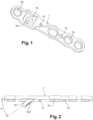
figure 1 est une vue en perspective d'une forme de réalisation de la plaque ; - la
figure 2 est une vue de profil de la plaque ; - les
figures 3 et 4 sont des vues en perspective montrant le montage de la plaque entre deux parties d'os et la composition de ces dernières, au moyen de la plaque selon l'invention, les parties d'os étant présentées d'une manière schématique.
- there
figure 1 is a perspective view of one embodiment of the plate; - there
picture 2 - THE
figures 3 and 4 are perspective views showing the assembly of the plate between two bone parts and the composition of the latter, by means of the plate according to the invention, the bone parts being shown schematically.
Selon l'invention, la plaque (1) présente au moins un agencement (la) apte à permettre de positionner au moins une vis (2), d'une manière inclinée, selon un angle α compris entre 30° et 60° par rapport au plan défini par ladite plaque (
Dans une forme de réalisation, l'agencement (la) est constitué par une zone inclinée qui résulte d'une découpe et d'une déformation d'une partie de la plaque. Par exemple, la déformation est consécutive à une opération de découpage - poinçonnage. Cette zone inclinée constitue une nervure qui présente un trou (1a1) pour l'engagement de la vis (2). La nervure inclinée (la) est formée sur une partie déterminée de la longueur de la plaque pour qu'après engagement, la vis (2) assure la mise en compression des deux parties d'os, comme il sera indiqué dans la suite de la description.In one embodiment, the arrangement (la) consists of an inclined zone which results from cutting and deforming part of the plate. For example, the deformation is consecutive to a cutting-punching operation. This inclined zone constitutes a rib which has a hole (1a1) for the engagement of the screw (2). The inclined rib (la) is formed on a determined part of the length of the plate so that, after engagement, the screw (2) ensures the compression of the two parts of bone, as will be indicated in the continuation of the description.
Dans une autre forme de réalisation, pour permettre une orientation angulaire de la vis (2), selon un angle compris entre 30° et 60° environ, l'agencement (la) peut être constitué par un trou incliné. A noter que la nervure (la) permet une adaptation de l'angle en fonction du cas pathologique à traiter étant donné qu'il est possible de déformer à volonté cette nervure. Autrement dit, l'angle peut être réglé directement par le chirurgien sur quelques degrés en bloc opératoire avec un instrument adapté.In another embodiment, to allow an angular orientation of the screw (2), according to an angle comprised between 30° and 60° approximately, the arrangement (la) can be constituted by an inclined hole. It should be noted that the rib (la) allows an adaptation of the angle according to the pathological case to be treated since it is possible to deform this rib at will. In other words, the angle can be adjusted directly by the surgeon over a few degrees in the operating room with a suitable instrument.
On renvoie aux
- Après réalisation des ostéotomies, un gabarit de la plaque, qui ne présente pas de nervures, permet de déterminer la position de cette nervure.
- Après avoir déterminé le positionnement de la nervure, le chirurgien réalise un logement correspondant, avec une râpe adaptée.
- Après positionnement de la plaque présentant la nervure, le chirurgien met en place une ou deux vis (3), d'un côté du foyer d'ostéosynthèse de l'arthrodèse considéré du côté de la nervure. On peut positionner, éventuellement, une broche de fixation temporaire dans un plot adapté.
- La vis (2) est ensuite engagée dans le trou (1a1) de la nervure (la) pour mettre le foyer de fracture en compression.
- Une fois la compression effectuée, le chirurgien peut visser une ou plusieurs autres vis (3) de fixation complémentaire et retirer la broche temporaire de maintien
- After performing the osteotomies, a template of the plate, which has no ribs, makes it possible to determine the position of this rib.
- After having determined the position of the rib, the surgeon makes a corresponding housing, with a suitable rasp.
- After positioning the plate presenting the rib, the surgeon places one or two screws (3), on one side of the osteosynthesis site of arthrodesis considered from the side of the rib. A temporary fixation pin can be positioned, if necessary, in a suitable stud.
- The screw (2) is then engaged in the hole (1a1) of the rib (la) to put the fracture site in compression.
- Once compression has been performed, the surgeon can screw in one or more additional fixation screws (3) and remove the temporary retaining pin.
D'une manière connue, cette plaque (1) présente des trous lisses et/ou taraudés (1b) pour l'engagement des vis de fixation (3) vissées dans les parties d'os (O1) et (O2), comme il ressort des
De même, la plaque (1) peut présenter au moins un logement (le) pour l'introduction d'une broche en vue d'assurer une fixation temporaire de ladite plaque (1). Avantageusement, la plaque (1) peut présenter un logement (lc) pour l'introduction d'une broche du côté de l'une des parties de l'os (O1) et un autre logement (ld) pour l'introduction d'une autre broche du côté de l'autre partie d'os (O2).Similarly, the plate (1) may have at least one housing (le) for the introduction of a pin in order to provide temporary fixing of said plate (1). Advantageously, the plate (1) may have a housing (lc) for the introduction of a pin on the side of one of the parts of the bone (O1) and another housing (ld) for the introduction of another pin on the side of the other bone part (O2).
Compte tenu de l'effet de compression recherchée, telle qu'indiquée précédemment, le logement (le) est constitué par un trou circulaire dont le diamètre correspond sensiblement à celui de la broche (4), tandis que l'autre logement (1d) peut être constitué par une lumière oblongue.Given the desired compression effect, as indicated above, the housing (le) consists of a circular hole whose diameter corresponds substantially to that of the pin (4), while the other housing (1d) can be constituted by an oblong lumen.
Ces dispositions permettent donc à l'os de coulisser sous la plaque (1) au moment du vissage, tout en assurant une compression selon une direction précise, généralement suivant l'axe de la plaque. Les broches sont de tout type connu et approprié, et parfaitement connu pour un homme du métier.These provisions therefore allow the bone to slide under the plate (1) at the time of screwing, while providing compression in a specific direction, generally along the axis of the plate. The pins are of any known and appropriate type, and well known to a person skilled in the art.
La plaque (1) peut présenter différentes formes géométriques, de sorte que les trous (la) notamment peuvent être alignés ou être disposés, en totalité ou en partie, selon les sommets d'un triangle ou d'un quadrilatère. Ces dispositions, en triangle ou en quadrilatère des vis, améliorent la stabilité du montage.The plate (1) can have different geometric shapes, so that the holes (la) in particular can be aligned or be arranged, in whole or in part, according to the vertices of a triangle or a quadrilateral. These arrangements, in triangle or quadrilateral of the screws, improve the stability of the assembly.
A noter également que la plaque (1), quelle que soit sa forme géométrique, peut être cintrée longitudinalement, pour s'adapter à la courbure de l'os permettant, en conséquence, aux vis (2) de former un angle entre elles.It should also be noted that the plate (1), whatever its geometric shape, can be bent longitudinally, to adapt to the curvature of the bone allowing, consequently, the screws (2) to form an angle between them.
Les avantages ressortent bien de la description.The benefits are clear from the description.
Claims (11)
- A system including an implant having a structure in the form of a plate (1) for compressing together first (O1) and second bone (02) parts separated by a joint, the implant comprising:the plate (1) having a top surface, a bottom bone-contacting surface, and a plurality of holes (1b) formed through the top and bottom surfaces, wherein a first hole of the plurality of holes (1b) can be positioned on a first side of the joint, and a second hole of the plurality of holes (1b) can be positioned on a second side of the joint, the first and second holes being adapted to receive first and second fixation members (3), respectively, a central axis of the first hole extending into the first bone part (O1) but not the second bone part (02), and a central axis of the second hole extending into the second bone part (02) but not the first bone part (O1); anda formation (1a) made of a rib forming an angled hole (1a1) extending through the plate (1) at an angle between 30° and 60° with respect to the bottom bone-contacting surface, the angled hole (1a1) being formed on a location on a determined portion of a length of the plate (1) and adapted to receive a third fixation member (2), a central axis of the angled hole (1a1) being angled with respect to a longitudinal axis of the plate, such that when the third fixation member (2) is inserted through the angled hole (1a1), it is arranged to extend into the first bone part (O1), across the joint, and into the second bone part (02) and to compress together the first bone part (O1) and the second bone part (02) in a direction along the longitudinal axis of the plate,characterized in that the system further comprises a template of the plate for use in determining the positioning of the formation (1a) against bone, wherein the template does not include any rib.
- The system of claim 1, wherein the first and second holes are locking holes.
- The system of claim 2, wherein the first and second holes include threading for engaging with the first and second fixation members (3).
- The system of any one of claims 1 to 3, wherein the plate (1) is curved so as to adapt to the curvature of the first (O1) and second (02) bone parts, the curvature of the plate arranging at least two of the fixation members at an angle with respect to one another.
- The system of any one of claims 1 to 4, wherein at least three of the plurality of holes (1b) are arranged according to the corners of a triangle.
- The system of any one of claims 1 to 4, wherein at least four of the plurality of holes (1b) are arranged according to the corners of a quadrilateral.
- The system of any one of claims 1 to 4, wherein the angled hole (1a1) is aligned with the first and second holes of the plurality of holes (1b).
- The system of any one of claims 1 to 7, wherein the formation (1a) is situated between and extends below adjacent sides of the plate, such that the formation is receivable in a cavity formed in at least one of the first (O1) and second (02) bones.
- The system of any one of claims 1 to 8, wherein the formation extends below the bottom surface and is consequently situated below a slot formed in the plate (1), the slot is bounded by side walls extending through the top and bottom surfaces of the plate, the side walls being dimensioned to allow insertion of the third fixation member (2) through the slot and into the angled hole (1a1).
- The system of claim 9, wherein the angled hole (1a1) has a first diameter, and a head of the third fixation member (2) has a second diameter, the second diameter being larger than the first diameter.
- The system of any one of claims 1 to 10, further comprising screws for insertion into the plurality of holes of the implant.
Applications Claiming Priority (3)
| Application Number | Priority Date | Filing Date | Title |
|---|---|---|---|
| FR0856694A FR2936700B1 (en) | 2008-10-02 | 2008-10-02 | ORTHOPEDIC IMPLANT IN THE FORM OF A PLATE TO BE FIXED BETWEEN TWO BONE PARTS |
| EP09756159.1A EP2334245B1 (en) | 2008-10-02 | 2009-10-02 | Orthopedic implant in the form of a plate to be fixed between two bone parts |
| PCT/FR2009/051879 WO2010037985A1 (en) | 2008-10-02 | 2009-10-02 | Orthopedic implant in the form of a plate to be fixed between two bone parts |
Related Parent Applications (1)
| Application Number | Title | Priority Date | Filing Date |
|---|---|---|---|
| EP09756159.1A Division EP2334245B1 (en) | 2008-10-02 | 2009-10-02 | Orthopedic implant in the form of a plate to be fixed between two bone parts |
Publications (2)
| Publication Number | Publication Date |
|---|---|
| EP3170466A1 EP3170466A1 (en) | 2017-05-24 |
| EP3170466B1 true EP3170466B1 (en) | 2023-06-21 |
Family
ID=40433892
Family Applications (2)
| Application Number | Title | Priority Date | Filing Date |
|---|---|---|---|
| EP09756159.1A Active EP2334245B1 (en) | 2008-10-02 | 2009-10-02 | Orthopedic implant in the form of a plate to be fixed between two bone parts |
| EP16202035.8A Active EP3170466B1 (en) | 2008-10-02 | 2009-10-02 | Orthopedic implant in the form of a plate to be fixed between two bone parts |
Family Applications Before (1)
| Application Number | Title | Priority Date | Filing Date |
|---|---|---|---|
| EP09756159.1A Active EP2334245B1 (en) | 2008-10-02 | 2009-10-02 | Orthopedic implant in the form of a plate to be fixed between two bone parts |
Country Status (8)
| Country | Link |
|---|---|
| US (7) | US8556946B2 (en) |
| EP (2) | EP2334245B1 (en) |
| JP (1) | JP5696268B2 (en) |
| AU (1) | AU2009299628B2 (en) |
| CA (1) | CA2738892C (en) |
| ES (1) | ES2618102T3 (en) |
| FR (1) | FR2936700B1 (en) |
| WO (1) | WO2010037985A1 (en) |
Families Citing this family (51)
| Publication number | Priority date | Publication date | Assignee | Title |
|---|---|---|---|---|
| US7951176B2 (en) | 2003-05-30 | 2011-05-31 | Synthes Usa, Llc | Bone plate |
| US11259851B2 (en) | 2003-08-26 | 2022-03-01 | DePuy Synthes Products, Inc. | Bone plate |
| DE20321245U1 (en) | 2003-08-26 | 2006-06-14 | Synthes Gmbh | bone plate |
| US8574268B2 (en) | 2004-01-26 | 2013-11-05 | DePuy Synthes Product, LLC | Highly-versatile variable-angle bone plate system |
| US11291484B2 (en) | 2004-01-26 | 2022-04-05 | DePuy Synthes Products, Inc. | Highly-versatile variable-angle bone plate system |
| US8303589B2 (en) | 2008-06-24 | 2012-11-06 | Extremity Medical Llc | Fixation system, an intramedullary fixation assembly and method of use |
| US9017329B2 (en) | 2008-06-24 | 2015-04-28 | Extremity Medical, Llc | Intramedullary fixation assembly and method of use |
| US8313487B2 (en) | 2008-06-24 | 2012-11-20 | Extremity Medical Llc | Fixation system, an intramedullary fixation assembly and method of use |
| US8343199B2 (en) * | 2008-06-24 | 2013-01-01 | Extremity Medical, Llc | Intramedullary fixation screw, a fixation system, and method of fixation of the subtalar joint |
| US9044282B2 (en) * | 2008-06-24 | 2015-06-02 | Extremity Medical Llc | Intraosseous intramedullary fixation assembly and method of use |
| US9289220B2 (en) * | 2008-06-24 | 2016-03-22 | Extremity Medical Llc | Intramedullary fixation assembly and method of use |
| US8328806B2 (en) * | 2008-06-24 | 2012-12-11 | Extremity Medical, Llc | Fixation system, an intramedullary fixation assembly and method of use |
| FR2936700B1 (en) | 2008-10-02 | 2012-04-13 | Memometal Technologies | ORTHOPEDIC IMPLANT IN THE FORM OF A PLATE TO BE FIXED BETWEEN TWO BONE PARTS |
| US8986353B2 (en) | 2009-07-09 | 2015-03-24 | Orthohelix Surgical Designs, Inc. | Osteotomy plate, plate driver and method for their use |
| US8870963B2 (en) | 2010-10-27 | 2014-10-28 | Toby Orthopaedics, Inc. | System and method for fracture replacement of comminuted bone fractures or portions thereof adjacent bone joints |
| US9005255B2 (en) * | 2011-02-15 | 2015-04-14 | Orthohelix Surgical Designs, Inc. | Orthopedic compression plate |
| EP2494934B1 (en) * | 2011-03-04 | 2015-12-16 | Stryker Trauma SA | Bone plate |
| US9066768B2 (en) * | 2011-06-29 | 2015-06-30 | Nextremity Solutions, Inc. | Bone plate hybrid device |
| US9730797B2 (en) | 2011-10-27 | 2017-08-15 | Toby Orthopaedics, Inc. | Bone joint replacement and repair assembly and method of repairing and replacing a bone joint |
| US9271772B2 (en) | 2011-10-27 | 2016-03-01 | Toby Orthopaedics, Inc. | System and method for fracture replacement of comminuted bone fractures or portions thereof adjacent bone joints |
| US9060822B2 (en) | 2011-12-28 | 2015-06-23 | Orthohelix Surgical Designs, Inc. | Orthopedic compression plate and method of surgery |
| CN104168848A (en) * | 2012-03-14 | 2014-11-26 | 新特斯有限责任公司 | Pelvic bone plate |
| US9907588B2 (en) | 2012-09-06 | 2018-03-06 | Orthohelix Surgical Designs, Inc. | Orthopedic dual pocket compression plate and method of surgery |
| US9283008B2 (en) | 2012-12-17 | 2016-03-15 | Toby Orthopaedics, Inc. | Bone plate for plate osteosynthesis and method for use thereof |
| EP2938279B1 (en) | 2012-12-28 | 2018-11-14 | Paragon 28, Inc. | Alignment guide system |
| US9358053B2 (en) | 2013-03-01 | 2016-06-07 | Stryker European Holdings I, Llc | Pelvic bone plate |
| US9333014B2 (en) * | 2013-03-15 | 2016-05-10 | Eduardo Gonzalez-Hernandez | Bone fixation and reduction apparatus and method for fixation and reduction of a distal bone fracture and malunion |
| JP6936146B2 (en) | 2015-01-07 | 2021-09-15 | トリース メディカル コンセプツ,インコーポレイティド | Bone plate fixation system and method |
| USD819209S1 (en) * | 2015-08-07 | 2018-05-29 | Paragon 28, Inc. | Calc-slide bone plate |
| AU2016215127B2 (en) | 2015-02-05 | 2020-12-03 | Paragon 28, Inc. | Bone plates, systems, and methods of use |
| WO2016134160A1 (en) | 2015-02-18 | 2016-08-25 | Treace Medical Concepts, Inc. | Bone plating kit for foot and ankle applications |
| FR3052047B1 (en) | 2016-06-02 | 2021-12-17 | Neosteo | IMPLANTABLE MEDICAL DEVICE FOR THE SOLIDARIZATION OF SEPARATED BONE PARTS WITH A VIEW OF THEIR FUSION |
| US10820930B2 (en) | 2016-09-08 | 2020-11-03 | DePuy Synthes Products, Inc. | Variable angle bone plate |
| US10905476B2 (en) | 2016-09-08 | 2021-02-02 | DePuy Synthes Products, Inc. | Variable angle bone plate |
| US10624686B2 (en) | 2016-09-08 | 2020-04-21 | DePuy Synthes Products, Inc. | Variable angel bone plate |
| US10610241B2 (en) | 2016-10-24 | 2020-04-07 | Paragon 28, Inc. | Osteotomy systems, devices and methods |
| EP3585287A4 (en) | 2017-02-27 | 2021-05-05 | Paragon 28, Inc. | Intramedullary nail alignment guides, fixation guides, devices, systems, and methods of use |
| USD841166S1 (en) * | 2017-03-08 | 2019-02-19 | Paragon 28, Inc. | Hook plate |
| US10918431B2 (en) | 2017-03-30 | 2021-02-16 | Paragon 28, Inc. | Bone fixation system, assembly, implants, devices, alignment guides, and methods of use |
| EP3651699A4 (en) * | 2017-07-11 | 2021-05-19 | Paragon 28, Inc. | Bone fixation system, assembly, implants, devices, insertion guides, and methods of use |
| USD847343S1 (en) * | 2017-11-02 | 2019-04-30 | Paragon 28, Inc. | Hook plate |
| EP3720368B1 (en) * | 2017-12-08 | 2024-01-24 | Paragon 28, Inc. | Bone fixation assembly and implants |
| US11026727B2 (en) | 2018-03-20 | 2021-06-08 | DePuy Synthes Products, Inc. | Bone plate with form-fitting variable-angle locking hole |
| US10772665B2 (en) | 2018-03-29 | 2020-09-15 | DePuy Synthes Products, Inc. | Locking structures for affixing bone anchors to a bone plate, and related systems and methods |
| US11013541B2 (en) | 2018-04-30 | 2021-05-25 | DePuy Synthes Products, Inc. | Threaded locking structures for affixing bone anchors to a bone plate, and related systems and methods |
| WO2020014418A1 (en) | 2018-07-11 | 2020-01-16 | Paragon 28, Inc. | Implants, alignment guides, systems and methods of use |
| WO2020014660A1 (en) | 2018-07-12 | 2020-01-16 | Treace Medical Concepts, Inc. | Multi-diameter bone pin for installing and aligning bone fixation plate while minimizing bone damage |
| US10925651B2 (en) | 2018-12-21 | 2021-02-23 | DePuy Synthes Products, Inc. | Implant having locking holes with collection cavity for shavings |
| CA3129469A1 (en) | 2019-02-13 | 2020-08-20 | Paragon 28, Inc. | Implant, alignment guides, system and methods of use |
| US20220409248A1 (en) | 2019-08-07 | 2022-12-29 | Crossroads Extremity Systems, Llc | Bunion correction system and method |
| US11890039B1 (en) | 2019-09-13 | 2024-02-06 | Treace Medical Concepts, Inc. | Multi-diameter K-wire for orthopedic applications |
Family Cites Families (148)
| Publication number | Priority date | Publication date | Assignee | Title |
|---|---|---|---|---|
| FR590290A (en) * | 1924-12-10 | 1925-06-13 | Collin & Cie | Osteosynthesis splint |
| US2486303A (en) | 1948-04-29 | 1949-10-25 | Harry Herschel Leiter | Surgical appliance for bone fractures |
| USRE28841E (en) * | 1966-06-22 | 1976-06-08 | Synthes A.G. | Osteosynthetic pressure plate construction |
| CH462375A (en) | 1966-06-22 | 1968-09-15 | Synthes Ag | Osteosynthetic pressure plate |
| USRE31628E (en) | 1966-06-22 | 1984-07-10 | Synthes Ag | Osteosynthetic pressure plate construction |
| FR1538053A (en) | 1967-08-18 | 1968-09-07 | Osteosynthesis plate combined with its key | |
| US3528085A (en) | 1968-03-22 | 1970-09-08 | Walker Reynolds Jr | Bone compression plate |
| US3779240A (en) | 1972-03-31 | 1973-12-18 | S Kondo | Compression plate for osteosynthesis |
| FR2362616A1 (en) | 1976-08-26 | 1978-03-24 | Duyck Jean | Metatarsal osteotomy anchor plate - has curved support with hooks, and holes for anchoring screws |
| CH645013A5 (en) | 1980-04-14 | 1984-09-14 | Wenk Wilh Ag | Osteosynthetic COMPRESSION PLATE. |
| CH645264A5 (en) * | 1980-05-28 | 1984-09-28 | Straumann Inst Ag | FITTING WITH A PLATE AND SCREWS THAT FIX IT TO A BONE. |
| CH651192A5 (en) | 1980-11-20 | 1985-09-13 | Synthes Ag | OSTEOSYNTHETIC DEVICE AND CORRESPONDING DRILL GAUGE. |
| CH650915A5 (en) | 1981-03-16 | 1985-08-30 | Synthes Ag | DEVICE FOR STABILIZING THE AREA OF A BONE BREAK OR OSTEOTOMY. |
| DE8227727U1 (en) * | 1982-10-02 | 1982-12-16 | Howmedica International, Inc. Zweigniederlassung Kiel, 2301 Schönkirchen | OSTEOSYNTHESIS TOOLS FOR TREATING FRACTURES OF THE DENS AXIS |
| US4503737A (en) | 1983-04-11 | 1985-03-12 | Digiovanni Donald | Threaded fastener removing tool |
| GB2158716B (en) | 1984-05-18 | 1987-09-30 | Technomed Gmk | Bone joining plate |
| AT387711B (en) | 1986-07-15 | 1989-03-10 | David Thomas | BONE FIXATION PLATE |
| DE3630862A1 (en) * | 1986-09-08 | 1988-03-17 | Mecron Med Prod Gmbh | Osteosynthesis part |
| DE8808123U1 (en) | 1988-06-24 | 1988-09-22 | Herzberg, Wolfgang, Dr. Med., 2000 Wedel, De | |
| DE3838774A1 (en) | 1988-11-11 | 1990-05-17 | Mecron Med Prod Gmbh | SLIDING PLATE |
| US5105690A (en) | 1991-03-29 | 1992-04-21 | Implant Innovations, Inc. | Manipulator-driver for holding and driving a screw-type article |
| US5304180A (en) | 1992-01-17 | 1994-04-19 | Slocum D Barclay | Tibial osteotomy fixation plate |
| FR2693899B1 (en) | 1992-07-24 | 1994-09-23 | Laboureau Jacques | Osteosynthesis plate clip. |
| JPH0748247Y2 (en) | 1992-11-16 | 1995-11-08 | 株式会社タグチ | Bone joint |
| US5347894A (en) | 1993-05-28 | 1994-09-20 | Pmt Corporation | Torque limiting device |
| US5558674A (en) * | 1993-12-17 | 1996-09-24 | Smith & Nephew Richards, Inc. | Devices and methods for posterior spinal fixation |
| FR2719211B1 (en) | 1994-04-27 | 1996-07-19 | Mortier Jean Pierre | Equipment for correcting foot deformities. |
| WO1995032674A1 (en) | 1994-06-01 | 1995-12-07 | Synthes Ag, Chur | Forked bone plate |
| WO1996005778A1 (en) | 1994-08-23 | 1996-02-29 | Spinetech, Inc. | Cervical spine stabilization system |
| US5601553A (en) | 1994-10-03 | 1997-02-11 | Synthes (U.S.A.) | Locking plate and bone screw |
| SE508120C2 (en) | 1995-01-27 | 1998-08-31 | Robert J Medoff | Implantable device comprising a pin plate and pins |
| US5709686A (en) | 1995-03-27 | 1998-01-20 | Synthes (U.S.A.) | Bone plate |
| US5667510A (en) | 1995-08-03 | 1997-09-16 | Combs; C. Robert | Joint fixation system and method |
| US5718705A (en) | 1996-07-16 | 1998-02-17 | Sammarco; Giacomo J. | Internal fixation plate |
| US5827285A (en) | 1996-12-12 | 1998-10-27 | Bramlet; Dale G. | Multipiece interfragmentary fixation assembly |
| JP4467647B2 (en) | 1997-02-11 | 2010-05-26 | ウォーソー・オーソペディック・インコーポレーテッド | Bone plating system |
| US5904684A (en) | 1997-04-16 | 1999-05-18 | Rooks; Robert L. | Device and method for simultaneous bilateral pelvic osteotomies |
| US5853413A (en) | 1997-04-18 | 1998-12-29 | Bristol-Myers Squibb Company | Wrist fusion plate |
| ZA983955B (en) | 1997-05-15 | 2001-08-13 | Sdgi Holdings Inc | Anterior cervical plating system. |
| FR2764183B1 (en) | 1997-06-09 | 1999-11-05 | Jacques Afriat | MATERIAL ALLOWING THE CORRECTION OF "HALLUX VALGUS" |
| US5938664A (en) | 1998-03-31 | 1999-08-17 | Zimmer, Inc. | Orthopaedic bone plate |
| US6533786B1 (en) | 1999-10-13 | 2003-03-18 | Sdgi Holdings, Inc. | Anterior cervical plating system |
| US6258089B1 (en) | 1998-05-19 | 2001-07-10 | Alphatec Manufacturing, Inc. | Anterior cervical plate and fixation system |
| US6146382A (en) | 1998-09-23 | 2000-11-14 | Spinal Concepts, Inc. | Occipito-cervical stabilization system and method |
| US6183475B1 (en) | 1998-12-18 | 2001-02-06 | Sulzer Orthopedics Inc. | Distal femoral osteotomy system and method |
| AUPP830499A0 (en) | 1999-01-22 | 1999-02-18 | Cryptych Pty Ltd | Method and apparatus for delivering bio-active compounds to specified sites in the body |
| CA2367085C (en) | 1999-03-09 | 2007-08-07 | Synthes (U.S.A.) | Bone plate with partly-threaded elongated hole |
| EP1175181B1 (en) | 1999-05-03 | 2005-01-12 | Medartis AG | Blockable bone plate |
| DE29909025U1 (en) | 1999-05-25 | 1999-11-04 | Lipat Consulting Ag Basel | Osteosynthetic bone plate |
| EP1211992B1 (en) | 1999-09-13 | 2004-01-14 | Synthes AG Chur | Bone plate system |
| US6692503B2 (en) | 1999-10-13 | 2004-02-17 | Sdgi Holdings, Inc | System and method for securing a plate to the spinal column |
| ES2253202T3 (en) | 2000-01-27 | 2006-06-01 | Synthes Ag Chur | PLATE FOR OSTEOSYNTHESIS. |
| US6440135B2 (en) | 2000-02-01 | 2002-08-27 | Hand Innovations, Inc. | Volar fixation system with articulating stabilization pegs |
| US6712820B2 (en) | 2000-02-01 | 2004-03-30 | Hand Innovations, Inc. | Fixation plate system for dorsal wrist fracture fixation |
| US6379359B1 (en) | 2000-05-05 | 2002-04-30 | University Of North Carolina At Chapel Hill | Percutaneous intrafocal plate system |
| US6576018B1 (en) | 2000-06-23 | 2003-06-10 | Edward S. Holt | Apparatus configuration and method for treating flatfoot |
| SE525131C2 (en) | 2001-01-15 | 2004-12-07 | Artimplant Ab | Implants for reconstruction of joints |
| US7044951B2 (en) * | 2001-02-12 | 2006-05-16 | Robert J. Medoff | Fracture fixation device in which a fixation pin is axially restrained |
| US6440131B1 (en) | 2001-03-09 | 2002-08-27 | Mayo Foundation For Medical Education And Research | Acetabular bone plate |
| US6565570B2 (en) | 2001-03-14 | 2003-05-20 | Electro-Biology, Inc. | Bone plate and retractor assembly |
| US6843790B2 (en) | 2001-03-27 | 2005-01-18 | Bret A. Ferree | Anatomic posterior lumbar plate |
| ES2263617T3 (en) | 2001-05-28 | 2006-12-16 | Synthes Ag Chur | OSTEOSYNTHESIS PLATE FOR FIXING PROXIMAL FRACTURES OF THE HUMER. |
| AUPR546601A0 (en) * | 2001-06-05 | 2001-06-28 | Australian Surgical Design And Manufacture Pty Limited | High tibial osteotomy device |
| US7316687B2 (en) * | 2001-08-24 | 2008-01-08 | Zimmer Technology, Inc. | Blade plate and instruments |
| FR2829920B1 (en) | 2001-09-26 | 2004-05-28 | Newdeal Sa | PLATE FOR FIXING THE BONES OF A JOINT, PARTICULARLY A METATARSO-PHALANGIAN JOINT |
| US20060235408A1 (en) | 2001-11-09 | 2006-10-19 | Wang Robert C | Apparatus and methods for bone fracture fixation |
| US20050090825A1 (en) | 2002-02-15 | 2005-04-28 | Medartis Ag | Bone plate |
| ITBO20020224A1 (en) | 2002-04-23 | 2003-10-23 | Citieffe Srl | STABILIZER SUPPORT FOR ADDITION AND SUBTRACTION OSTEOTOMIES |
| US8652142B2 (en) | 2006-04-28 | 2014-02-18 | Acumed Llc | Osteotomy systems |
| US7179260B2 (en) * | 2003-09-29 | 2007-02-20 | Smith & Nephew, Inc. | Bone plates and bone plate assemblies |
| US20040092929A1 (en) | 2002-09-27 | 2004-05-13 | Zindrick Michael R. | Spinal plate with means to secure a graft |
| FR2846870B1 (en) | 2002-11-07 | 2005-07-01 | Fixano | OSTEOSYNTHESIS EQUIPMENT FOR THE TREATMENT OF A "LONG" CUBITUS |
| USD587370S1 (en) | 2003-02-26 | 2009-02-24 | Zimmer Gmbh | Bone plate |
| FR2851452B1 (en) | 2003-02-26 | 2005-04-22 | Ct Pulse Orthopedics Ltd | MINI-BLADE ANATOMIC PLATE ALLOWING OSTEOSYNTHESIS OF THE FIRST PHALANGE |
| USD596294S1 (en) | 2003-02-26 | 2009-07-14 | Zimmer, Gmbh | Bone plate |
| ATE331475T1 (en) | 2003-03-20 | 2006-07-15 | Stryker Trauma Sa | BONE CONNECTION DEVICE |
| US7722653B2 (en) | 2003-03-26 | 2010-05-25 | Greatbatch Medical S.A. | Locking bone plate |
| ATE476149T1 (en) | 2003-03-26 | 2010-08-15 | Swiss Orthopedic Solutions Sa | FIXING BONE PLATE |
| US7819903B2 (en) | 2003-03-31 | 2010-10-26 | Depuy Spine, Inc. | Spinal fixation plate |
| US7144252B2 (en) | 2003-04-25 | 2006-12-05 | James Walton | Dental tool with shear pin handle |
| US7951176B2 (en) * | 2003-05-30 | 2011-05-31 | Synthes Usa, Llc | Bone plate |
| WO2005074580A2 (en) | 2004-02-02 | 2005-08-18 | Acumed Llc | Bone plate with toothed aperture |
| WO2006091827A2 (en) | 2005-02-25 | 2006-08-31 | Regents Of The University Of California | Device and template for canine humeral slide osteotomy |
| US7540874B2 (en) | 2004-05-27 | 2009-06-02 | Trimed Inc. | Method and device for use in osteotomy |
| GB2414673A (en) | 2004-06-02 | 2005-12-07 | Vineet Dev Tandon | A bone plate |
| US20050277937A1 (en) | 2004-06-10 | 2005-12-15 | Leung Takkwong R | Bone plating system |
| US7137987B2 (en) | 2004-07-02 | 2006-11-21 | Wright Medical Technology, Inc. | Distal radius bone plating system with locking and non-locking screws |
| FR2873015B1 (en) | 2004-07-15 | 2007-12-28 | Newdeal Sa Sa | FASTENING IMPLANT FOR THE OSTEOSYNTHESIS OF FRAGMENTS OF A FIRST FRACTURE OR OSTEOTOMIZED METATARSIS IN ITS PROXIMAL PART AND CORRESPONDING OSTEOSYNTHESIS METHOD |
| US20060058796A1 (en) | 2004-09-14 | 2006-03-16 | Hartdegen Vernon R | Compression brace |
| US20060106387A1 (en) | 2004-11-16 | 2006-05-18 | Depuy Spine, Inc. | Spinal plate system and method of use |
| US7166111B2 (en) | 2004-12-08 | 2007-01-23 | Depuy Spine, Inc. | Spinal plate and drill guide |
| US8118846B2 (en) | 2005-01-28 | 2012-02-21 | Orthohelix Surgical Designs, Inc. | Orthopedic plates for use in clavicle repair and methods for their use |
| US8118848B2 (en) | 2005-01-28 | 2012-02-21 | Orthohelix Surgical Designs, Inc. | Orthopedic plate for use in fibula repair |
| US7771457B2 (en) | 2005-01-28 | 2010-08-10 | Orthohelix Surgical Designs, Inc. | Orthopedic plate for use in small bone repair |
| ATE383829T1 (en) * | 2005-03-11 | 2008-02-15 | Orthofix Srl | DEVICE FOR OSTEOSYNTHESIS OF PROXIMAL HUBER FRACTURES |
| WO2006099766A1 (en) | 2005-03-24 | 2006-09-28 | Medartis Ag | Bone plate |
| US7931680B2 (en) | 2005-03-31 | 2011-04-26 | Depuy Products, Inc. | Plate for lengthening the lateral column of the foot |
| US20060241607A1 (en) | 2005-03-31 | 2006-10-26 | Mark Myerson | Metatarsal fixation plate |
| US7344538B2 (en) | 2005-03-31 | 2008-03-18 | Depuy Products, Inc. | Mid-foot fixation plate |
| US20060235397A1 (en) | 2005-03-31 | 2006-10-19 | Roy Sanders | Navicular fixation device |
| US20060241608A1 (en) | 2005-03-31 | 2006-10-26 | Mark Myerson | Plate for fusion of the metatarso-phalangeal joint |
| US7766948B1 (en) | 2005-05-05 | 2010-08-03 | Ebi, Llc | Bone fixation assembly |
| KR101318537B1 (en) | 2005-07-13 | 2013-10-16 | 어큠드 엘엘씨 | Bone plates with movable locking elements |
| JP2007151674A (en) | 2005-12-01 | 2007-06-21 | Hidetoshi Onoe | Bone plate |
| US20070142920A1 (en) | 2005-12-20 | 2007-06-21 | Niemi Willard J | Metatarsal implant |
| ATE380512T1 (en) | 2005-12-23 | 2007-12-15 | Aap Implantate Ag | BONE PLATE |
| US8523921B2 (en) | 2006-02-24 | 2013-09-03 | DePuy Synthes Products, LLC | Tibial plateau leveling osteotomy plate |
| BRPI0601069B1 (en) | 2006-03-17 | 2014-10-14 | Gm Dos Reis Ind E Com Ltda | BONE BOARD |
| CA2679639A1 (en) | 2006-05-17 | 2007-11-22 | Gordon Slater | Ankle fusion plate |
| FR2905590B1 (en) * | 2006-09-11 | 2008-12-05 | Surge Foot | ARTHRODESIS PLATE OF A METATARSO-PHALANGEAL ARTICULATION. |
| US8187276B1 (en) * | 2006-09-26 | 2012-05-29 | Zahiri Christopher A | Odd angle internal bone fixation device for use in a transverse fracture of a humerus |
| US7993379B2 (en) * | 2006-11-10 | 2011-08-09 | Da Frota Carrera Eduardo | Bone fastening plate |
| US8968369B2 (en) | 2007-02-26 | 2015-03-03 | Life Spine, Inc. | Spine plate with bone screw relief area |
| FR2912895B1 (en) | 2007-02-28 | 2009-05-01 | Small Bone Innovations Interna | MATERIAL OF ARTHODESIS |
| US8556944B2 (en) | 2007-07-31 | 2013-10-15 | Stryker Spine | System and method for vertebral body plating |
| US20090093849A1 (en) | 2007-10-03 | 2009-04-09 | Greg Grabowski | Metatarsal fixation system |
| BRPI0818918A8 (en) * | 2007-11-02 | 2015-09-08 | Depuy Products Inc | ELBOW FRACTURE FIXATION SYSTEM |
| US20090198285A1 (en) | 2008-02-06 | 2009-08-06 | Raven Iii Raymond | Subcondylar fracture fixation plate system for tubular bones of the hand |
| US8257406B2 (en) | 2008-02-19 | 2012-09-04 | Orthohelix Surgical Designs, Inc. | Orthopedic plate for use on a single ray in the midfoot |
| US8257403B2 (en) | 2008-02-19 | 2012-09-04 | Orthohelix Surgical Designs, Inc. | Orthopedic plate for use in the midfoot |
| US8167918B2 (en) | 2008-02-19 | 2012-05-01 | Orthohelix Surgical Designs, Inc. | Orthopedic plate for use in the MTP joint |
| US20090228048A1 (en) | 2008-03-10 | 2009-09-10 | Duncan Scott F M | Joint Fixation System For the Hand |
| US8652179B2 (en) | 2008-05-02 | 2014-02-18 | The Cleveland Clinic Foundation | Bone plate extender and extension system for bone restoration and methods of use thereof |
| US9017329B2 (en) | 2008-06-24 | 2015-04-28 | Extremity Medical, Llc | Intramedullary fixation assembly and method of use |
| US8343199B2 (en) | 2008-06-24 | 2013-01-01 | Extremity Medical, Llc | Intramedullary fixation screw, a fixation system, and method of fixation of the subtalar joint |
| US8328806B2 (en) | 2008-06-24 | 2012-12-11 | Extremity Medical, Llc | Fixation system, an intramedullary fixation assembly and method of use |
| US20110125153A1 (en) | 2008-06-24 | 2011-05-26 | Jeff Tyber | Intramedullary fixation assembly and method of use |
| US9044282B2 (en) | 2008-06-24 | 2015-06-02 | Extremity Medical Llc | Intraosseous intramedullary fixation assembly and method of use |
| US8303589B2 (en) | 2008-06-24 | 2012-11-06 | Extremity Medical Llc | Fixation system, an intramedullary fixation assembly and method of use |
| US20100121325A1 (en) | 2008-06-24 | 2010-05-13 | Jeff Tyber | Hybrid intramedullary fixation assembly and method of use |
| US8313487B2 (en) | 2008-06-24 | 2012-11-20 | Extremity Medical Llc | Fixation system, an intramedullary fixation assembly and method of use |
| US20110230884A1 (en) | 2008-06-24 | 2011-09-22 | Adam Mantzaris | Hybrid intramedullary fixation assembly and method of use |
| SE533632C2 (en) * | 2008-07-01 | 2010-11-09 | Swemac Innovation Ab | Device for internal fixation of the bone fragments in a bone fracture |
| US8167891B2 (en) | 2008-07-21 | 2012-05-01 | Osteomed Llc | System and method for fracture reduction |
| US8506641B2 (en) | 2008-09-03 | 2013-08-13 | The Cleveland Clinic Foundation | Arthrodesis implant for finger joints and related methods |
| FR2936700B1 (en) | 2008-10-02 | 2012-04-13 | Memometal Technologies | ORTHOPEDIC IMPLANT IN THE FORM OF A PLATE TO BE FIXED BETWEEN TWO BONE PARTS |
| FR2936699B1 (en) | 2008-10-02 | 2012-01-13 | Memometal Technologies | ORTHOPEDIC IMPLANT IN THE FORM OF A PLATE TO BE FIXED BETWEEN TWO BONE PARTS |
| US8828063B2 (en) | 2008-11-19 | 2014-09-09 | Amei Technologies, Inc. | Fixation plate for use in the Lapidus approach |
| US8100983B2 (en) | 2008-11-25 | 2012-01-24 | Schulte Robert C | Intra-osseus fusion system |
| USD623745S1 (en) | 2009-02-17 | 2010-09-14 | Orthohelix Surgical Designs, Inc. | Orthopedic plate |
| US8246664B2 (en) | 2009-02-24 | 2012-08-21 | Osteomed Llc | Multiple bone fusion plate |
| US8529608B2 (en) | 2009-04-28 | 2013-09-10 | Osteomed Llc | Bone plate with a transfixation screw hole |
| US8986353B2 (en) | 2009-07-09 | 2015-03-24 | Orthohelix Surgical Designs, Inc. | Osteotomy plate, plate driver and method for their use |
| US20110087229A1 (en) | 2009-10-12 | 2011-04-14 | University Of Utah | Bone fixation and compression systems |
| US8657820B2 (en) | 2009-10-12 | 2014-02-25 | Tornier, Inc. | Bone plate and keel systems |
| US8551107B2 (en) | 2009-10-15 | 2013-10-08 | Biomet, C.V. | Bending tool and method for reshaping a bone plate |
| US8348980B2 (en) | 2009-10-15 | 2013-01-08 | Biomet C.V. | Method and plate for fusing the medial column bones of the foot |
| US8764807B2 (en) | 2010-06-10 | 2014-07-01 | Arthrex, Inc. | Calcaneus step plate |
-
2008
- 2008-10-02 FR FR0856694A patent/FR2936700B1/en active Active
-
2009
- 2009-10-02 EP EP09756159.1A patent/EP2334245B1/en active Active
- 2009-10-02 US US12/918,071 patent/US8556946B2/en active Active
- 2009-10-02 ES ES09756159.1T patent/ES2618102T3/en active Active
- 2009-10-02 JP JP2011529607A patent/JP5696268B2/en active Active
- 2009-10-02 CA CA2738892A patent/CA2738892C/en active Active
- 2009-10-02 WO PCT/FR2009/051879 patent/WO2010037985A1/en active Application Filing
- 2009-10-02 EP EP16202035.8A patent/EP3170466B1/en active Active
- 2009-10-02 AU AU2009299628A patent/AU2009299628B2/en active Active
-
2013
- 2013-09-30 US US14/041,706 patent/US9078713B2/en active Active
-
2015
- 2015-06-09 US US14/734,676 patent/US9333013B2/en active Active
-
2016
- 2016-04-15 US US15/130,147 patent/US10349988B2/en active Active
-
2019
- 2019-06-03 US US16/429,834 patent/US11534212B2/en active Active
-
2021
- 2021-01-07 US US17/143,709 patent/US10993751B1/en active Active
-
2022
- 2022-11-21 US US17/990,936 patent/US20230084400A1/en active Pending
Also Published As
| Publication number | Publication date |
|---|---|
| US20190282281A1 (en) | 2019-09-19 |
| US8556946B2 (en) | 2013-10-15 |
| US20160228164A1 (en) | 2016-08-11 |
| EP3170466A1 (en) | 2017-05-24 |
| US20230084400A1 (en) | 2023-03-16 |
| WO2010037985A1 (en) | 2010-04-08 |
| US20210121213A1 (en) | 2021-04-29 |
| JP5696268B2 (en) | 2015-04-08 |
| US11534212B2 (en) | 2022-12-27 |
| US9333013B2 (en) | 2016-05-10 |
| FR2936700B1 (en) | 2012-04-13 |
| JP2012504444A (en) | 2012-02-23 |
| US10993751B1 (en) | 2021-05-04 |
| US20140052193A1 (en) | 2014-02-20 |
| CA2738892C (en) | 2014-08-05 |
| CA2738892A1 (en) | 2010-04-08 |
| US20110046681A1 (en) | 2011-02-24 |
| US20150265324A1 (en) | 2015-09-24 |
| EP2334245A1 (en) | 2011-06-22 |
| EP2334245B1 (en) | 2016-12-07 |
| FR2936700A1 (en) | 2010-04-09 |
| AU2009299628B2 (en) | 2014-05-01 |
| ES2618102T3 (en) | 2017-06-20 |
| US10349988B2 (en) | 2019-07-16 |
| US9078713B2 (en) | 2015-07-14 |
| AU2009299628A1 (en) | 2010-04-08 |
Similar Documents
| Publication | Publication Date | Title |
|---|---|---|
| EP3170466B1 (en) | Orthopedic implant in the form of a plate to be fixed between two bone parts | |
| EP2334247B1 (en) | Orthopedic implant in the form of a plate to be fixed between two bone parts | |
| EP1119305A1 (en) | Spinal osteosynthesis system with improved stability | |
| EP1616528A1 (en) | Fixation implant for osteosynthesis of fragments of the first metatarsal bone after fracture or osteotomy in its proximal part | |
| FR2935601A1 (en) | INTRAMEDULLARY IMPLANT RESORBABLE BETWEEN TWO BONE OR TWO BONE FRAGMENTS | |
| FR2680461A1 (en) | IMPLANT FOR OSTEOSYNTHESIS DEVICE, ESPECIALLY OF THE RACHIS, AND CORRESPONDING DEVICE FOR ITS PLACEMENT. | |
| WO1996036291A1 (en) | Implantable osteosynthesis device | |
| EP1123056A1 (en) | Anterior osteosynthesis plate for lumbar vertebrae or sacral lumbar vertebra and instrument for positioning same | |
| CA2330705A1 (en) | Backbone osteosynthesis system for anterior fixing | |
| FR2890848A1 (en) | OSTEOSYNTHESIS DEVICE. | |
| FR2827150A1 (en) | Surgical prosthesis auto-retaining screw bolt clamp, clamp strap has countersunk variable diameter hole into which bolt head fits after elastic deformation of hole opening | |
| EP2288302A1 (en) | Hook for vertebral osteosynthesis device, and device including same | |
| FR2743490A1 (en) | Staple for orthopaedic surgery | |
| EP3206607B1 (en) | Intramedullary nail | |
| FR2785519A1 (en) | Osteosynthesis plate has interchangeable wedge mounted on plate with faces engaging opposed faces of osteotomy | |
| FR2830742A1 (en) | Spinal osteosynthesis apparatus with screws and connectors has linking rod with secondary angled section | |
| FR2720261A1 (en) | Osteosynthesis device implant | |
| FR2802796A1 (en) | Bolt for connecting vertebra to longitudinal member, e.g. spine | |
| EP2807985B1 (en) | Humeral plate | |
| FR2935254A1 (en) | EXTERNAL FASTENING SYSTEM FOR REALIZING OSTEOSYNTHESIS BETWEEN TWO BONE PORTIONS | |
| FR2899094A1 (en) | Bone plate for repairing e.g. comminuted fracture of olecranon, has curved shaped epiphyseal portion broadened with respect to narrow diaphyseal portion and including threaded holes to receive threaded screws | |
| FR2990618A1 (en) | AUTOCOMPRESSIVE SCREW OF OSTEOSYNTHESIS | |
| FR3027209A1 (en) | MULTI-AXIAL VERTEBRAL ANCHORING DEVICE FOR RESTRICTING A VERTEBRA | |
| FR2932375A1 (en) | Bones distracting device for reducing spondylolisthesis between vertebral bodies of patient, has application unit applying opposed forces on plate and part of screw shaft, where forces are defined on straight line parallel to orifice's axis | |
| FR2835733A1 (en) | Osteosynthesis fixing for vertebrae has flat plate with hole to receive threaded shaft of fixing screw and recesses to receive ends of jaws |
Legal Events
| Date | Code | Title | Description |
|---|---|---|---|
| PUAI | Public reference made under article 153(3) epc to a published international application that has entered the european phase |
Free format text: ORIGINAL CODE: 0009012 |
|
| STAA | Information on the status of an ep patent application or granted ep patent |
Free format text: STATUS: THE APPLICATION HAS BEEN PUBLISHED |
|
| AC | Divisional application: reference to earlier application |
Ref document number: 2334245 Country of ref document: EP Kind code of ref document: P |
|
| AK | Designated contracting states |
Kind code of ref document: A1 Designated state(s): AT BE BG CH CY CZ DE DK EE ES FI FR GB GR HR HU IE IS IT LI LT LU LV MC MK MT NL NO PL PT RO SE SI SK SM TR |
|
| STAA | Information on the status of an ep patent application or granted ep patent |
Free format text: STATUS: REQUEST FOR EXAMINATION WAS MADE |
|
| 17P | Request for examination filed |
Effective date: 20171123 |
|
| RBV | Designated contracting states (corrected) |
Designated state(s): AT BE BG CH CY CZ DE DK EE ES FI FR GB GR HR HU IE IS IT LI LT LU LV MC MK MT NL NO PL PT RO SE SI SK SM TR |
|
| STAA | Information on the status of an ep patent application or granted ep patent |
Free format text: STATUS: EXAMINATION IS IN PROGRESS |
|
| 17Q | First examination report despatched |
Effective date: 20180122 |
|
| STAA | Information on the status of an ep patent application or granted ep patent |
Free format text: STATUS: EXAMINATION IS IN PROGRESS |
|
| STAA | Information on the status of an ep patent application or granted ep patent |
Free format text: STATUS: EXAMINATION IS IN PROGRESS |
|
| RAP1 | Party data changed (applicant data changed or rights of an application transferred) |
Owner name: STRYKER EUROPEAN OPERATIONS HOLDINGS LLC |
|
| GRAP | Despatch of communication of intention to grant a patent |
Free format text: ORIGINAL CODE: EPIDOSNIGR1 |
|
| STAA | Information on the status of an ep patent application or granted ep patent |
Free format text: STATUS: GRANT OF PATENT IS INTENDED |
|
| INTG | Intention to grant announced |
Effective date: 20221117 |
|
| GRAJ | Information related to disapproval of communication of intention to grant by the applicant or resumption of examination proceedings by the epo deleted |
Free format text: ORIGINAL CODE: EPIDOSDIGR1 |
|
| STAA | Information on the status of an ep patent application or granted ep patent |
Free format text: STATUS: EXAMINATION IS IN PROGRESS |
|
| GRAP | Despatch of communication of intention to grant a patent |
Free format text: ORIGINAL CODE: EPIDOSNIGR1 |
|
| STAA | Information on the status of an ep patent application or granted ep patent |
Free format text: STATUS: GRANT OF PATENT IS INTENDED |
|
| INTC | Intention to grant announced (deleted) | ||
| INTG | Intention to grant announced |
Effective date: 20230120 |
|
| GRAS | Grant fee paid |
Free format text: ORIGINAL CODE: EPIDOSNIGR3 |
|
| GRAA | (expected) grant |
Free format text: ORIGINAL CODE: 0009210 |
|
| STAA | Information on the status of an ep patent application or granted ep patent |
Free format text: STATUS: THE PATENT HAS BEEN GRANTED |
|
| P01 | Opt-out of the competence of the unified patent court (upc) registered |
Effective date: 20230428 |
|
| AC | Divisional application: reference to earlier application |
Ref document number: 2334245 Country of ref document: EP Kind code of ref document: P |
|
| AK | Designated contracting states |
Kind code of ref document: B1 Designated state(s): AT BE BG CH CY CZ DE DK EE ES FI FR GB GR HR HU IE IS IT LI LT LU LV MC MK MT NL NO PL PT RO SE SI SK SM TR |
|
| REG | Reference to a national code |
Ref country code: CH Ref legal event code: EP |
|
| REG | Reference to a national code |
Ref country code: DE Ref legal event code: R096 Ref document number: 602009064895 Country of ref document: DE |
|
| REG | Reference to a national code |
Ref country code: AT Ref legal event code: REF Ref document number: 1580335 Country of ref document: AT Kind code of ref document: T Effective date: 20230715 |
|
| REG | Reference to a national code |
Ref country code: IE Ref legal event code: FG4D Free format text: LANGUAGE OF EP DOCUMENT: FRENCH |
|
| REG | Reference to a national code |
Ref country code: LT Ref legal event code: MG9D |
|
| REG | Reference to a national code |
Ref country code: NL Ref legal event code: MP Effective date: 20230621 |
|
| PG25 | Lapsed in a contracting state [announced via postgrant information from national office to epo] |
Ref country code: SE Free format text: LAPSE BECAUSE OF FAILURE TO SUBMIT A TRANSLATION OF THE DESCRIPTION OR TO PAY THE FEE WITHIN THE PRESCRIBED TIME-LIMIT Effective date: 20230621 Ref country code: NO Free format text: LAPSE BECAUSE OF FAILURE TO SUBMIT A TRANSLATION OF THE DESCRIPTION OR TO PAY THE FEE WITHIN THE PRESCRIBED TIME-LIMIT Effective date: 20230921 |
|
| PGFP | Annual fee paid to national office [announced via postgrant information from national office to epo] |
Ref country code: GB Payment date: 20230831 Year of fee payment: 15 |
|
| REG | Reference to a national code |
Ref country code: AT Ref legal event code: MK05 Ref document number: 1580335 Country of ref document: AT Kind code of ref document: T Effective date: 20230621 |
|
| PG25 | Lapsed in a contracting state [announced via postgrant information from national office to epo] |
Ref country code: NL Free format text: LAPSE BECAUSE OF FAILURE TO SUBMIT A TRANSLATION OF THE DESCRIPTION OR TO PAY THE FEE WITHIN THE PRESCRIBED TIME-LIMIT Effective date: 20230621 Ref country code: LV Free format text: LAPSE BECAUSE OF FAILURE TO SUBMIT A TRANSLATION OF THE DESCRIPTION OR TO PAY THE FEE WITHIN THE PRESCRIBED TIME-LIMIT Effective date: 20230621 Ref country code: LT Free format text: LAPSE BECAUSE OF FAILURE TO SUBMIT A TRANSLATION OF THE DESCRIPTION OR TO PAY THE FEE WITHIN THE PRESCRIBED TIME-LIMIT Effective date: 20230621 Ref country code: HR Free format text: LAPSE BECAUSE OF FAILURE TO SUBMIT A TRANSLATION OF THE DESCRIPTION OR TO PAY THE FEE WITHIN THE PRESCRIBED TIME-LIMIT Effective date: 20230621 Ref country code: GR Free format text: LAPSE BECAUSE OF FAILURE TO SUBMIT A TRANSLATION OF THE DESCRIPTION OR TO PAY THE FEE WITHIN THE PRESCRIBED TIME-LIMIT Effective date: 20230922 |
|
| PGFP | Annual fee paid to national office [announced via postgrant information from national office to epo] |
Ref country code: FR Payment date: 20230911 Year of fee payment: 15 |
|
| PG25 | Lapsed in a contracting state [announced via postgrant information from national office to epo] |
Ref country code: FI Free format text: LAPSE BECAUSE OF FAILURE TO SUBMIT A TRANSLATION OF THE DESCRIPTION OR TO PAY THE FEE WITHIN THE PRESCRIBED TIME-LIMIT Effective date: 20230621 |
|
| PG25 | Lapsed in a contracting state [announced via postgrant information from national office to epo] |
Ref country code: SK Free format text: LAPSE BECAUSE OF FAILURE TO SUBMIT A TRANSLATION OF THE DESCRIPTION OR TO PAY THE FEE WITHIN THE PRESCRIBED TIME-LIMIT Effective date: 20230621 |
|
| PG25 | Lapsed in a contracting state [announced via postgrant information from national office to epo] |
Ref country code: ES Free format text: LAPSE BECAUSE OF FAILURE TO SUBMIT A TRANSLATION OF THE DESCRIPTION OR TO PAY THE FEE WITHIN THE PRESCRIBED TIME-LIMIT Effective date: 20230621 |
|
| PG25 | Lapsed in a contracting state [announced via postgrant information from national office to epo] |
Ref country code: IS Free format text: LAPSE BECAUSE OF FAILURE TO SUBMIT A TRANSLATION OF THE DESCRIPTION OR TO PAY THE FEE WITHIN THE PRESCRIBED TIME-LIMIT Effective date: 20231021 |
|
| PG25 | Lapsed in a contracting state [announced via postgrant information from national office to epo] |
Ref country code: SM Free format text: LAPSE BECAUSE OF FAILURE TO SUBMIT A TRANSLATION OF THE DESCRIPTION OR TO PAY THE FEE WITHIN THE PRESCRIBED TIME-LIMIT Effective date: 20230621 Ref country code: SK Free format text: LAPSE BECAUSE OF FAILURE TO SUBMIT A TRANSLATION OF THE DESCRIPTION OR TO PAY THE FEE WITHIN THE PRESCRIBED TIME-LIMIT Effective date: 20230621 Ref country code: RO Free format text: LAPSE BECAUSE OF FAILURE TO SUBMIT A TRANSLATION OF THE DESCRIPTION OR TO PAY THE FEE WITHIN THE PRESCRIBED TIME-LIMIT Effective date: 20230621 Ref country code: PT Free format text: LAPSE BECAUSE OF FAILURE TO SUBMIT A TRANSLATION OF THE DESCRIPTION OR TO PAY THE FEE WITHIN THE PRESCRIBED TIME-LIMIT Effective date: 20231023 Ref country code: IS Free format text: LAPSE BECAUSE OF FAILURE TO SUBMIT A TRANSLATION OF THE DESCRIPTION OR TO PAY THE FEE WITHIN THE PRESCRIBED TIME-LIMIT Effective date: 20231021 Ref country code: ES Free format text: LAPSE BECAUSE OF FAILURE TO SUBMIT A TRANSLATION OF THE DESCRIPTION OR TO PAY THE FEE WITHIN THE PRESCRIBED TIME-LIMIT Effective date: 20230621 Ref country code: EE Free format text: LAPSE BECAUSE OF FAILURE TO SUBMIT A TRANSLATION OF THE DESCRIPTION OR TO PAY THE FEE WITHIN THE PRESCRIBED TIME-LIMIT Effective date: 20230621 Ref country code: CZ Free format text: LAPSE BECAUSE OF FAILURE TO SUBMIT A TRANSLATION OF THE DESCRIPTION OR TO PAY THE FEE WITHIN THE PRESCRIBED TIME-LIMIT Effective date: 20230621 Ref country code: AT Free format text: LAPSE BECAUSE OF FAILURE TO SUBMIT A TRANSLATION OF THE DESCRIPTION OR TO PAY THE FEE WITHIN THE PRESCRIBED TIME-LIMIT Effective date: 20230621 |
|
| PGFP | Annual fee paid to national office [announced via postgrant information from national office to epo] |
Ref country code: DE Payment date: 20230830 Year of fee payment: 15 Ref country code: CH Payment date: 20231102 Year of fee payment: 15 |
|
| PG25 | Lapsed in a contracting state [announced via postgrant information from national office to epo] |
Ref country code: PL Free format text: LAPSE BECAUSE OF FAILURE TO SUBMIT A TRANSLATION OF THE DESCRIPTION OR TO PAY THE FEE WITHIN THE PRESCRIBED TIME-LIMIT Effective date: 20230621 |