EP3170450B1 - Pastille comprenant un filtre passe-haut flottant externe et pastille d'électrocardiographe (ecg) la comprenant - Google Patents
Pastille comprenant un filtre passe-haut flottant externe et pastille d'électrocardiographe (ecg) la comprenant Download PDFInfo
- Publication number
- EP3170450B1 EP3170450B1 EP16199339.9A EP16199339A EP3170450B1 EP 3170450 B1 EP3170450 B1 EP 3170450B1 EP 16199339 A EP16199339 A EP 16199339A EP 3170450 B1 EP3170450 B1 EP 3170450B1
- Authority
- EP
- European Patent Office
- Prior art keywords
- ecg
- patch
- voltage
- electrode
- signal
- Prior art date
- Legal status (The legal status is an assumption and is not a legal conclusion. Google has not performed a legal analysis and makes no representation as to the accuracy of the status listed.)
- Active
Links
- 238000012545 processing Methods 0.000 claims description 50
- 230000005540 biological transmission Effects 0.000 claims description 32
- 239000003990 capacitor Substances 0.000 claims description 10
- 238000001914 filtration Methods 0.000 claims description 10
- 230000001105 regulatory effect Effects 0.000 claims description 3
- 238000010586 diagram Methods 0.000 description 12
- 238000001514 detection method Methods 0.000 description 11
- 239000010410 layer Substances 0.000 description 10
- 238000004891 communication Methods 0.000 description 7
- 230000036541 health Effects 0.000 description 6
- 238000000034 method Methods 0.000 description 6
- 238000010295 mobile communication Methods 0.000 description 5
- 230000008569 process Effects 0.000 description 5
- 239000012790 adhesive layer Substances 0.000 description 4
- 208000003663 ventricular fibrillation Diseases 0.000 description 4
- 206010003119 arrhythmia Diseases 0.000 description 3
- 206010049418 Sudden Cardiac Death Diseases 0.000 description 2
- 230000002238 attenuated effect Effects 0.000 description 2
- 230000008859 change Effects 0.000 description 2
- 230000008878 coupling Effects 0.000 description 2
- 238000010168 coupling process Methods 0.000 description 2
- 238000005859 coupling reaction Methods 0.000 description 2
- 230000000694 effects Effects 0.000 description 2
- 238000012544 monitoring process Methods 0.000 description 2
- 230000033764 rhythmic process Effects 0.000 description 2
- 208000014221 sudden cardiac arrest Diseases 0.000 description 2
- 206010047302 ventricular tachycardia Diseases 0.000 description 2
- 230000005856 abnormality Effects 0.000 description 1
- 230000003321 amplification Effects 0.000 description 1
- 238000004458 analytical method Methods 0.000 description 1
- 230000006793 arrhythmia Effects 0.000 description 1
- 239000008280 blood Substances 0.000 description 1
- 210000004369 blood Anatomy 0.000 description 1
- 230000001413 cellular effect Effects 0.000 description 1
- 230000002999 depolarising effect Effects 0.000 description 1
- 238000003745 diagnosis Methods 0.000 description 1
- 230000006870 function Effects 0.000 description 1
- 230000004217 heart function Effects 0.000 description 1
- 239000012212 insulator Substances 0.000 description 1
- 230000007774 longterm Effects 0.000 description 1
- 238000005442 molecular electronic Methods 0.000 description 1
- 238000003199 nucleic acid amplification method Methods 0.000 description 1
- 230000005180 public health Effects 0.000 description 1
- 230000003068 static effect Effects 0.000 description 1
- 238000012549 training Methods 0.000 description 1
- 238000012546 transfer Methods 0.000 description 1
Images


Classifications
-
- A—HUMAN NECESSITIES
- A61—MEDICAL OR VETERINARY SCIENCE; HYGIENE
- A61B—DIAGNOSIS; SURGERY; IDENTIFICATION
- A61B5/00—Measuring for diagnostic purposes; Identification of persons
- A61B5/24—Detecting, measuring or recording bioelectric or biomagnetic signals of the body or parts thereof
- A61B5/316—Modalities, i.e. specific diagnostic methods
-
- A—HUMAN NECESSITIES
- A61—MEDICAL OR VETERINARY SCIENCE; HYGIENE
- A61B—DIAGNOSIS; SURGERY; IDENTIFICATION
- A61B5/00—Measuring for diagnostic purposes; Identification of persons
- A61B5/72—Signal processing specially adapted for physiological signals or for diagnostic purposes
- A61B5/7203—Signal processing specially adapted for physiological signals or for diagnostic purposes for noise prevention, reduction or removal
-
- A—HUMAN NECESSITIES
- A61—MEDICAL OR VETERINARY SCIENCE; HYGIENE
- A61B—DIAGNOSIS; SURGERY; IDENTIFICATION
- A61B5/00—Measuring for diagnostic purposes; Identification of persons
- A61B5/24—Detecting, measuring or recording bioelectric or biomagnetic signals of the body or parts thereof
- A61B5/25—Bioelectric electrodes therefor
- A61B5/251—Means for maintaining electrode contact with the body
- A61B5/257—Means for maintaining electrode contact with the body using adhesive means, e.g. adhesive pads or tapes
- A61B5/259—Means for maintaining electrode contact with the body using adhesive means, e.g. adhesive pads or tapes using conductive adhesive means, e.g. gels
-
- A—HUMAN NECESSITIES
- A61—MEDICAL OR VETERINARY SCIENCE; HYGIENE
- A61B—DIAGNOSIS; SURGERY; IDENTIFICATION
- A61B5/00—Measuring for diagnostic purposes; Identification of persons
- A61B5/24—Detecting, measuring or recording bioelectric or biomagnetic signals of the body or parts thereof
- A61B5/25—Bioelectric electrodes therefor
- A61B5/279—Bioelectric electrodes therefor specially adapted for particular uses
- A61B5/28—Bioelectric electrodes therefor specially adapted for particular uses for electrocardiography [ECG]
- A61B5/282—Holders for multiple electrodes
-
- A—HUMAN NECESSITIES
- A61—MEDICAL OR VETERINARY SCIENCE; HYGIENE
- A61B—DIAGNOSIS; SURGERY; IDENTIFICATION
- A61B5/00—Measuring for diagnostic purposes; Identification of persons
- A61B5/24—Detecting, measuring or recording bioelectric or biomagnetic signals of the body or parts thereof
- A61B5/30—Input circuits therefor
- A61B5/301—Input circuits therefor providing electrical separation, e.g. by using isolating transformers or optocouplers
-
- A—HUMAN NECESSITIES
- A61—MEDICAL OR VETERINARY SCIENCE; HYGIENE
- A61B—DIAGNOSIS; SURGERY; IDENTIFICATION
- A61B5/00—Measuring for diagnostic purposes; Identification of persons
- A61B5/68—Arrangements of detecting, measuring or recording means, e.g. sensors, in relation to patient
- A61B5/6801—Arrangements of detecting, measuring or recording means, e.g. sensors, in relation to patient specially adapted to be attached to or worn on the body surface
- A61B5/6813—Specially adapted to be attached to a specific body part
- A61B5/6823—Trunk, e.g., chest, back, abdomen, hip
-
- A—HUMAN NECESSITIES
- A61—MEDICAL OR VETERINARY SCIENCE; HYGIENE
- A61B—DIAGNOSIS; SURGERY; IDENTIFICATION
- A61B5/00—Measuring for diagnostic purposes; Identification of persons
- A61B5/68—Arrangements of detecting, measuring or recording means, e.g. sensors, in relation to patient
- A61B5/6801—Arrangements of detecting, measuring or recording means, e.g. sensors, in relation to patient specially adapted to be attached to or worn on the body surface
- A61B5/683—Means for maintaining contact with the body
- A61B5/6832—Means for maintaining contact with the body using adhesives
-
- A—HUMAN NECESSITIES
- A61—MEDICAL OR VETERINARY SCIENCE; HYGIENE
- A61B—DIAGNOSIS; SURGERY; IDENTIFICATION
- A61B5/00—Measuring for diagnostic purposes; Identification of persons
- A61B5/72—Signal processing specially adapted for physiological signals or for diagnostic purposes
- A61B5/7235—Details of waveform analysis
- A61B5/725—Details of waveform analysis using specific filters therefor, e.g. Kalman or adaptive filters
-
- A—HUMAN NECESSITIES
- A61—MEDICAL OR VETERINARY SCIENCE; HYGIENE
- A61B—DIAGNOSIS; SURGERY; IDENTIFICATION
- A61B2560/00—Constructional details of operational features of apparatus; Accessories for medical measuring apparatus
- A61B2560/04—Constructional details of apparatus
- A61B2560/0406—Constructional details of apparatus specially shaped apparatus housings
- A61B2560/0412—Low-profile patch shaped housings
-
- A—HUMAN NECESSITIES
- A61—MEDICAL OR VETERINARY SCIENCE; HYGIENE
- A61B—DIAGNOSIS; SURGERY; IDENTIFICATION
- A61B2560/00—Constructional details of operational features of apparatus; Accessories for medical measuring apparatus
- A61B2560/04—Constructional details of apparatus
- A61B2560/0462—Apparatus with built-in sensors
- A61B2560/0468—Built-in electrodes
-
- A—HUMAN NECESSITIES
- A61—MEDICAL OR VETERINARY SCIENCE; HYGIENE
- A61B—DIAGNOSIS; SURGERY; IDENTIFICATION
- A61B2562/00—Details of sensors; Constructional details of sensor housings or probes; Accessories for sensors
- A61B2562/22—Arrangements of medical sensors with cables or leads; Connectors or couplings specifically adapted for medical sensors
- A61B2562/221—Arrangements of sensors with cables or leads, e.g. cable harnesses
- A61B2562/222—Electrical cables or leads therefor, e.g. coaxial cables or ribbon cables
-
- A—HUMAN NECESSITIES
- A61—MEDICAL OR VETERINARY SCIENCE; HYGIENE
- A61B—DIAGNOSIS; SURGERY; IDENTIFICATION
- A61B5/00—Measuring for diagnostic purposes; Identification of persons
- A61B5/24—Detecting, measuring or recording bioelectric or biomagnetic signals of the body or parts thereof
- A61B5/30—Input circuits therefor
Definitions
- Exemplary embodiments of the inventive concept relate to an electrocardiograph (ECG) patch, and more particularly, to an ECG patch including two electrodes and a floating high-pass filter.
- ECG electrocardiograph
- ECG monitoring is the process of recording the electrical activity of the heart over a period of time using electrodes placed on a person's body. These electrodes detect tiny electrical changes on the person's skin that arise from the heart depolarizing during each heartbeat.
- An ECG patch placed near the heart allows ECG signals to be easily acquired.
- an ECG patch includes ECG electrodes for detecting ECG signals and a bias electrode for supplying a bias voltage to a person's body.
- the bias electrode is typically attached to the person's body together with the ECG electrodes.
- US 2014/0221850 A1 there is known a monitor device and associated methodology for the monitoring of heart related parameters, including ECG.
- the detection of heart related parameters is predicated on the location of inequipotential signals located within regions of the human body conventionally defined as equivalent for the purpose of detection of heart related electrical activity.
- the device comprises a wearable sensor device adapted to be worn in an equivalence region of the individual; at least two electrodes attached to the wearable sensor device and adapted to be mounted within the equivalence region and to detect a heart-related signal; and a processor in electronic communication with the at least two electrodes an programmed to determine a sleep related parameter of the individual.
- US 2011/0009729 A1 there is known an apparatus for measuring physiological signals by distributing modules according to functions.
- the apparatus includes first and second detection electrodes, a physiological signal detection module, a power supply module, and a connection line.
- the detection electrodes are adhered to a target skin to detect physiological signals.
- the physiological signal detection module is installed at the first detection electrode to generate physiological signal from the physiological signals detected by the first and second detection electrodes.
- the power supply module is installed at the second detection electrode to supply power to the physiological signal detection module.
- a connection line connects the physiological signal detection module and the power supply module.
- an electrocardiograph (ECG) patch comprising: a first electrode; a second electrode; a high pass filter configured to receive a bias voltage and provide the bias voltage to the first electrode and the second electrode; and a signal processing unit configured to generate the bias voltage and provide the bias voltage to the high pass filter.
- ECG electrocardiograph
- an ECG patch comprising: a first patch including a first electrode, a high pass filter and an ECG signal processing unit; a second patch including a second electrode and a battery; and a cable including a first wire for providing a bias voltage from the first patch to the second electrode, a second wire for providing an operating voltage to the second patch and a third wire for providing a ground voltage to the second patch.
- a data processing system comprising: an ECG patch comprising a first electrode, a second electrode, a high pass filter configured to generate a bias voltage to be provided to the first electrode and the second electrode, and a wireless transceiver; and a mobile communication device configured to communicate with the ECG patch.
- a data processing system comprising: an ECG patch comprising a first electrode, a second electrode, a high pass filter configured to generate a bias voltage to be provided to the first electrode and the second electrode, and a wireless transceiver; a health care server configured to receive ECG medical data of a person wearing the ECG patch; and a mobile computing device configured to the receive the ECG medical data of the person from the health care server.
- an ECG patch comprises: a first electrode configured to detect a first ECG signal; a second electrode configured to detect a second ECG signal; a high-pass filter configured to perform high-pass filtering on the first ECG signal to generate a first high-pass filtered signal, and to perform high-pass filtering on the second ECG signal to generate a second high-pass filtered signal; and a signal processing unit configured to generate an ECG output signal based on a difference between the first ECG signal and the second ECG signal, wherein the high-pass filter is further configured to generate a first bias voltage based on a driving voltage and provide the first bias voltage to the first electrode, and to generate a second bias voltage based on the driving voltage and provide the second bias voltage to the second electrode.
- an ECG patch comprises: a first patch including a first electrode and an ECG sensor; a second patch including a second electrode; and a cable connected between the first patch and the second patch, wherein the ECG sensor is configured to receive a first high-pass filtered signal and a second high-pass filtered signal and amplify a voltage difference between the first and second high-pass filtered signals to generate an output voltage, wherein the first patch includes a high-pass filter configured to generate a first bias voltage and a second bias voltage using a driving voltage and to provide the first bias voltage to the first electrode and the second bias voltage to the second electrode.
- an ECG patch comprising: a first electrode; a second electrode; a wire; and a high-pass filter configured to generate a first bias voltage and a second bias voltage, apply the first bias voltage to the first electrode via a transmission line and apply the second bias voltage to the second electrode via the wire.
- an ECG patch comprising: a first electrode configured to detect a first ECG signal from a heart of a person; a second electrode configured to detect a second ECG signal from the heart of the person; a high-pass filter configured to perform high-pass filtering on the first ECG signal to generate a first high-pass filtered signal, and to perform high-pass filtering on the second ECG signal to generate a second high-pass filtered signal; and an ECG processing unit including an ECG sensor configured to sense a difference between the first high-pass filtered signal and the second high-pass filtered signal and generate an ECG output signal corresponding to the sensing result, and a bias voltage generating circuit configured to provide a bias voltage to the high pass filter.
- FIG. 1 is a perspective view of a wearable electrocardiograph (ECG) patch 100 including two ECG electrodes and a floating high-pass filter according to an exemplary embodiment of the inventive concept.
- FIG. 2 is a perspective view showing a state where the wearable ECG patch 100 illustrated in FIG. 1 is placed around a human heart, according to an exemplary embodiment of the inventive concept.
- ECG electrocardiograph
- the wearable ECG patch 100 may include a first patch 110, a second patch 150, and a cable 170.
- the wearable ECG patch 100 may be called an ECG patch or an ECG sensor patch.
- ECG electrodes 112 and 152 are placed on the patches 110 and 150, respectively.
- the wearable ECG patch 100 does not require special ECG electrodes for body biasing to be implemented in any of the patches 110 and 150. Accordingly, the wearable ECG patch 100 includes only two ECG electrodes 112 and 152.
- the ECG electrodes 112 and 152 are ECG electrodes or ECG signal electrodes which are placed on the body, and more particularly, around the heart of a person 300.
- reference numeral 111 denotes an adhesive layer for fixing or attaching the first ECG electrode 112 of the first patch 110 to the surface of the person's chest around the heart
- reference numeral 151 denotes an adhesive layer for fixing or attaching the second ECG electrode 152 of the second patch 150 to the surface of the person's chest around the heart.
- Each of the adhesive layers 111 and 151 may include a conductive gel but is not limited thereto.
- reference numerals 111 and 151 may denote disposable ECG electrodes which are electrically connected to ECG electrodes 112 and 152, respectively.
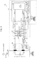
- FIG. 3 is a detailed block diagram of the wearable ECG patch 100 illustrated in FIG. 1 , according to an exemplary embodiment of the inventive concept.
- V ECG denotes the voltage of an ECG signal generated by the heartbeat of the person 300
- Z elec in an electrode interface model IFM denotes a contact impedance between each modeled ECG electrode 112 or 152 and the person 300
- V hc denotes a voltage difference, e.g., a direct current (DC) component between the ECG electrodes 112 and 152
- ⁇ Z denotes a difference between the impedance of the first patch 110 and the contact impedance of the second patch 150.
- ⁇ Z is one of the factors increasing motion noise.
- the motion noise may be increased by the motion of the person 300 or a physical difference between the ECG electrodes 112 and 152 (e.g., a difference between the thicknesses of the adhesive layers 111 and 151 existing between the respective ECG electrodes 112 and 152 and the body of the person 300).
- the contact impedance Z elec may be determined by resistance (e.g., 51 k ⁇ ) and capacitance (e.g., 47 nF) and the voltage difference V hc may be ⁇ 300 mV, but these values 51 k ⁇ , 47 nF, and ⁇ 300 mV are just examples.
- 50/60 Hz denotes power noise generated from a noise source (NS) and Ic denotes noise current generated from the NS.
- NS noise source
- Ic noise current generated from the NS.
- the power noise 50/60 Hz and the noise current Ic may influence the body of the person 300.
- Fc denotes capacitance between an earth ground (GND) and the body of the person 300;
- VSS PCB denotes a ground (or a ground of a printed circuit board (PCB)) of an ECG signal processing unit 120; and
- CC denotes capacitance between the earth GND and the PCB ground VSS PCB .
- the first patch 110 includes the first ECG electrode 112, the ECG signal processing unit 120, a high-pass filter 130, and transmission lines 122-1, 122-2, and L1.
- the first ECG electrode 112 may detect a first ECG signal from the heart of the person 300.
- the high-pass filter 130 may perform high-pass filtering on the first ECG signal to generate a first high-pass filtered ECG signal ECG_P.
- the ECG signal processing unit 120 may include a plurality of pads 121-1, 121-2, 121-3, 121-4, and 121-5, an ECG sensor 123, a voltage regulator 125, a voltage divider 127, and a driver 129.
- the ECG signal processing unit 120 which can process bio signals ECG_P and ECG_N, may be an ECG chip or a bio-processor.
- the ECG sensor 123 may sense a difference between the first high-pass filtered ECG signal ECG_P input through the first pad 121-1 and a second high-pass filtered ECG signal ECG_N input through the second pad 121-2 and may generate and process an ECG output signal corresponding to the sensing result.
- the voltage regulator 125 may receive an operating voltage VDD through the third pad 121-3, may regulate the operating voltage VDD, and may generate an operating voltage of the ECG sensor 123 included in the ECG signal processing unit 120.
- the operating voltage VDD is generated by a battery 154 embedded in the second patch 150 and may be supplied to the voltage regulator 125 through a second wire W2 and the third pad 121-3.
- the voltage divider 127 may divide the voltage (e.g., VDD) that has been regulated by the voltage regulator 125 to generate a driving voltage.
- the driving voltage may be VDD/2 but is not limited thereto.
- the driver 129 may drive the driving voltage VDD/2 to the high-pass filter 130 through the fifth pad 121-5.
- the driver 129 may have a gain of 1 and may be implemented as a current driver, but the inventive concept is not limited to this example.
- the high-pass filter 130 may generate a first bias voltage and a second bias voltage using the driving voltage VDD/2, may apply the first bias voltage to the body of the person 300 through the third transmission line L1 and the first ECG electrode 112, and may apply the second bias voltage to the body of the person 300 through a first wire W1 and the second ECG electrode 152.
- the level of the first bias voltage may be the same as the level of the second bias voltage, but the inventive concept is not limited to this example.
- the levels of the first and second bias voltages may be determined by the driving voltage, e.g., VDD/2, output from the driver 129 when the ECG electrodes 112 and 152 are attached to the body of the person 300.
- the first ECG electrode 112 may apply the first bias voltage to the body of the person 300 and detect a first ECG signal at a time
- the second ECG electrode 152 may apply the second bias voltage to the body of the person 300 and detect a second ECG signal at a time.
- the times may be the same, substantially simultaneous or different from each other.
- the high-pass filter 130 may be implemented as a floating high-pass filter.
- the high-pass filter 130 may include a plurality of capacitors 132 and 135 and a plurality of resistors 131, 133, 134, and 136.
- the high-pass filter 130 may be integrated into or placed within the ECG signal processing unit 120.
- the first capacitor 132 is connected between the third transmission line L1 and the first transmission line 122-1.
- the second capacitor 135 is connected between the first wire W1 and the second transmission line 122-2.
- the first transmission line 122-1 is connected to the first pad 121-1.
- the second transmission line 122-2 is connected to the second pad 121-2.
- the first resistor 131 is connected between the third transmission line L1 and a node ND connected to the fifth pad 121-5.
- the second resistor 133 is connected between the first transmission line 122-1 and the node ND.
- the third resistor 134 is connected between the node ND and the second transmission line 122-2.
- the fourth resistor 136 is connected between the node ND and the first wire W1.
- the capacitors 132 and 135 may have the same capacitance C and the resistors 131, 133, 134, and 136 may have the same resistance R. However, the resistors 131 and 136 may have a resistance R1 and the resistors 133 and 134 may have a resistance R2. In this case, the resistance R1 may be different from the resistance R2. Each of the resistors 131, 133, 134, and 136 may be a passive or an active resistance element. Each of the capacitors 132 and 135 may be a switched capacitor.
- a common-mode DC gain G CM, DC of the high-pass filter 130 may be 1.
- a cutoff frequency f HPf, -3dB of the high-pass filter 130 is 1/2 ⁇ RC and a differential input impedance Z in, Diff approximates R.
- a voltage of the first transmission line 122-1 is VDD/2 + G1 ⁇ V ECG /2 + V hc /2 and a voltage of the second transmission line 122-2 is VDD/2 - G1 ⁇ V ECG /2 + V hc /2, where G1 may denote a gain which is determined by the capacitance C, the resistance R2, and a frequency of the voltage V ECG .
- G1 may denote a gain which is determined by the capacitance C, the resistance R2, and a frequency of the voltage V ECG .
- differential DC inputs (e.g., V hc ) are attenuated by the high-pass filter 130 and the attenuated differential DC inputs may be eliminated from the ECG sensor 123.
- the body of the person 300 is biased by two resistors 131 and 136 and two ECG electrodes 112 and 152.
- the ECG patch 100 does not include a separate bias electrode for exclusively supplying a bias voltage.
- the ground of the battery 154 and the PCB ground VSS PCB may be connected with each other through a third wire W3 and the fourth pad 121-4.
- the second patch 150 may include the second electrode 152 and the battery 154.
- the second ECG signal detected by the second electrode 152 is transmitted to the high-pass filter 130 through the first wire W1.
- the high-pass filter 130 performs high-pass filtering on the second ECG signal to output the second high-pass filtered ECG signal ECG_N.
- the second high-pass filtered ECG signal ECG_N may be transmitted to the ECG sensor 123 through the second transmission line 122-2 and the second pad 121-2.
- the cable 170 may include the first wire W1 for transmitting the second ECG signal detected by the second ECG electrode 152 placed in the second patch 150 to the first patch 110, the second wire W2 for transmitting the operating voltage VDD to the first patch 110, and the third wire W3 for transmitting a ground voltage to the first patch 110.
- the cable 170 may be a shielded cable.
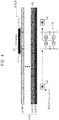
- FIG. 4 is a schematic diagram of the layout of the floating high-pass filter 130 and ECG transmission lines included in the first patch 110 of the wearable ECG patch 100 illustrated in FIG. 1 , according to an exemplary embodiment of the inventive concept.
- the ECG patch 100 when the ECG patch 100 is implemented in a PCB including a plurality of layers LAYER1 through LAYER6, the ECG signal processing unit 120 may be placed at the first layer LAYER1 and the high-pass filter 130 may be placed at the sixth layer LAYER6, but the inventive concept is not limited to the current embodiment.
- a first electrostatic discharge (ESD) protection circuit 140 may be placed between the electrodes 112 and 152 and the high-pass filter 130.
- the high-pass filter 130 may be placed as close as possible to the ECG sensor 123.
- a transmission line for supplying a ground voltage VSS may be placed at the fifth layer LAYER5.
- ESD protection circuits 140 and 142, the first transmission line 122-1 for transmitting the first high-pass filtered ECG signal ECG_P, and the second transmission line 122-2 for transmitting the second high-pass filtered ECG signal ECG_N may be placed at the sixth layer LAYER6, but the inventive concept is not limited to the current embodiment.
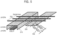
- FIG. 5 is a schematic diagram of the layout of a PCB included in the first patch 110 of the wearable ECG patch 100 illustrated in FIG. 1 , according to an exemplary embodiment of the inventive concept.
- a transmission line for transmitting the first high-pass filtered ECG signal ECG_P and the high-pass filter 130 are placed at the sixth layer LAYER6, a transmission line 210 placed at the fifth layer LAYER5 to transmit a ground voltage may have a structure for shielding the transmission line for transmitting the first high-pass filtered ECG signal ECG P to prevent coupling noise between digital lines 230 placed at the fourth layer LAYER4 and the transmission line placed at the sixth layer LAYER6 to transmit the first high-pass filtered ECG signal ECG_P.
- a shielding structure 220 or a shielding layer 220 may be placed between the digital lines 230 and the high-pass filter 130 to prevent coupling noise between the digital lines 230 and the high-pass filter 130.
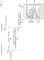
- FIG. 6 is a detailed block diagram of the wearable ECG patch illustrated in FIG. 1 , according to an exemplary embodiment of the inventive concept.
- an ECG processing unit 120-1 may include an ECG sensor 123, an analog-to-digital converter (ADC) 410, a central processing unit (CPU) 420, a memory controller 430, an internal memory device 435, a security circuit 440, and a wireless transceiver 450.
- the ECG patch may include a memory device 460 and a sensor 470.
- the ECG sensor 123 may receive a first high-pass filtered ECG signal ECG_P and a second high-pass filtered ECG signal ECG_N, process (or amplify) a voltage difference between the first high-pass filtered ECG signal ECG_P and the second high-pass filtered ECG signal ECG_N, and generate an ECG output corresponding to a result of the process (or amplification).
- the ADC 410 may convert the ECG output into an ECG digital signal and output the ECG digital signal to the CPU 420.
- the CPU 420 may analyze a heart rhythm of a person using the ECG digital signal.
- the CPU 420 may detect, predict, or analyze sudden cardiac arrest (SCA) of a person using the ECG digital signal.
- SCA sudden cardiac arrest
- the CPU 420 may detect, predict, or analyze cardiac arrhythmias such as ventricular fibrillation and/or ventricular tachycardia using the ECG digital signal.
- the memory controller 430 may transmit data related to the high-pass filtered ECG signals ECG P and ECG_N to the internal memory device 435 and/or the memory device 460 and receive data related to the high-pass filtered ECG signals ECG_P and ECG_N from the internal memory device 435 and/or the memory device 460.
- the internal memory device 435 may be a read only memory (ROM), a random access memory (RAM), a dynamic RAM (DRAM), or a static RAM (SRAM), but is not limited thereto.
- the memory device 460 may store a boot image for booting the ECG patch 100 and an application program to be performed by the CPU 420.
- the memory device 460 may comprise a volatile memory and/or a non-volatile memory.
- the volatile memory may be a RAM, a DRAM, or an SRAM, but is not limited thereto.
- the non-volatile memory may be an electrically erasable programmable ROM (EEPROM), a NAND-type flash memory, a NOR-type flash memory, a magnetic RAM (MRAM), a spin-transfer torque MRAM, a ferroelectric RAM (FeRAM), a phase change RAM (PRAM), a resistive RAM (RRAM), a holographic memory, a molecular electronics memory device, or an insulator resistance change memory, but is not limited thereto.
- EEPROM electrically erasable programmable ROM
- NAND-type flash memory a NOR-type flash memory
- MRAM magnetic RAM
- FeRAM ferroelectric RAM
- PRAM phase change RAM
- RRAM resistive RAM
- holographic memory a holographic memory
- molecular electronics memory device or an insulator resistance change memory, but is not limited thereto.
- the internal memory device 435 and/or the memory device 460 may store information on a person such as a patient (e.g., patient data) and/or data related to the high-pass filtered ECG signals ECG_P and ECG_N under the control of the memory controller 430.
- the data may include high-pass filtered ECG signals ECG_P and ECG_N, data related to a heart rate, data related to cardiac arrhythmias, data related to ventricular fibrillation (e.g., a history of ventricular fibrillation and a history of defibrillation), and/or sensing data generated by the sensor 470.
- the data may be encoded or decoded by the security circuit 440.
- the security circuit 440 may encode data output from the CPU 420 and related to a heart rhythm into security data, and output the encoded security data to the wireless transceiver 450. In addition, the security circuit 440 may decode the data transmitted from the wireless transceiver 450 and transmit the decoded data to the CPU 420.
- the security circuit 440 may be configured, e.g., programmed, with an encryption and decryption code.
- the wireless transceiver 450 may transmit encoded security data output from the security circuit 440 to an external Internet of Things (IoT) device 500 (e.g., a wireless communication device, a smart watch, a smart phone, a tablet personal computer (PC), a wearable computer, a mobile internet device, etc.) under the control of the CPU 440.
- IoT Internet of Things
- the ECG processing unit 120-1 may use a communication circuit, e.g., the wireless transceiver 450, for connecting to the external IoT device 500. For example, the ECG processing unit 120-1 may determine what kind of external smart device the communication circuit is connected to.
- the wireless transceiver 450 may transmit data related to the high-pass filtered ECG signals ECG_P and ECG_N, e.g., security data or biological data, to the external IoT device 500 through a local area network (LAN), a wireless LAN (WLAN) such as wireless fidelity (Wi-Fi), a wireless personal area network (WPAN) such as Bluetooth, a wireless universal serial bus (USB), a Zigbee connection, a near field communication (NFC) connection, a radio-frequency identification (RFID) connection, or a mobile cellular network.
- LAN local area network
- WLAN wireless LAN
- Wi-Fi wireless fidelity
- WPAN wireless personal area network
- USB wireless universal serial bus
- Zigbee Zigbee connection
- NFC near field communication
- RFID radio-frequency identification
- the mobile communication network may be a 3 rd generation (3G) mobile communication network, a 4 th generation (4G) mobile communication network, or a long term evolution mobile communication network (LTETM).
- the wireless transceiver 450 may include a transceiver and an antenna for modem communication.
- the Bluetooth interface may support Bluetooth Low Energy (BLE).
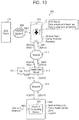
- FIG. 7 is a diagram of a data processing system which includes the ECG signal processing unit 120-1 shown in FIG. 6 , according to an exemplary embodiment of the inventive concept.
- a user of a IoT device 500 may execute, e.g., select for use, an application installed in the IoT device 500 (S110).
- a communication module (or wireless transceiver) of the IoT device 500 may transmit an information request to the ECG processing unit 120 or 120-1 (hereinafter collectively referred to as 120) under the control of the application performed by a CPU of the IoT device 500 (S120).
- a CPU 420 of the ECG processing unit 120 for example bio-processor 120, may require authentication by performing an information request through the wireless transceiver 450 (S130).
- the CPU 420 may read patient information and biological information from the memory device 435 or 460 using the memory controller 430, and transmit the patient information and the biological information to the wireless transceiver 450 through the security circuit 440.
- the wireless transceiver 450 may transmit the patient information and the biological information to the IoT device 500 through a wireless network (S140).
- the application executed by a CPU included in the IoT device 500 may display patient information 520 and/or biological information 530 on a display device 510 of the IoT device 500 (S150).
- the patient information 520 may include the age 521, blood type 522, family doctor (medical attendant) 523, and/or a medical history 524 of the patient.
- the biological information 530 may include heart rate 531 and an ECG waveform 532.
- a user of the IoT device 500 may determine a state of a patient to which the wearable ECG patch 100 is attached using the patient information 520 and/or the biological information 530, and perform a proper medical treatment or emergency diagnosis on the patient according to a result of the determination.
- FIGS. 8 , 9 , and 10 are diagrams illustrating data processing systems which include the wearable ECG patch shown in FIG. 1 , according to exemplary embodiments of the inventive concept.
- a data processing system 800A may be used to provide a telemedicine service.
- the data processing system 800A may include the wearable ECG patch 100 and a first medical server (health care sever) 820 which can communicate with the wearable ECG patch 100 through a wireless network 810, e.g., the internet or Wi-Fi.
- a wireless network 810 e.g., the internet or Wi-Fi.
- the data processing system 800A may further include a second medical server (health care server) 850 which can communicate with the wearable ECG patch 100 and/or the first medical server 820 through the wireless network 810.
- a health insurance corporation and/or an insurance company may manage the second medical server 850 and a database 855.
- the wireless transceiver 450 of the wearable ECG patch 100 may transmit data HDATA corresponding to the ECG signals ECG_P and ECG_N.
- the application may store a uniform resource locator (URL) of the first medical server 820 and/or a URL of the second medical server 850. Accordingly, the wireless transceiver 450 of the wearable ECG patch 100 may transmit data HDATA to the first medical server 820 (S801) and/or the second medical server 850 (S821) through the network 810 under the control of the CPU 420 or a control of an application program ("app") performed by the CPU 420.
- URL uniform resource locator
- the data HDATA may include the ECG signals ECG_P and ECG_N, data generated based on the ECG signals ECG_P and ECG_N, and patient information.
- data generated based on the ECG signals ECG P and ECG_N may include data on ventricular fibrillation, data on ventricular tachycardia, a heart rate, arrhythmia, or a defibrillation history of the patient, but is not limited thereto.
- the wireless network 810 may transmit the data HDATA to the first medical server 820 and/or the second medical server 850 (S803 and/or S821).
- the first medical server 820 may store the data HDATA in database 821 (S804), and transmit the data HDATA to a computing device 845 of a doctor working at a medical institution 840 through a network 830 (S805).
- the computing device 845 of a doctor may be a PC or a tablet PC, but is not limited thereto.
- the doctor may work at a medical institution, a public health care center, a clinic, a hospital, or a rescue center, for example.
- the doctor may diagnose a state of the patient using the data HDATA displayed through the computing device 845 and input diagnostic data into the computing device 845 (S807).
- the computing device 845 transmits the diagnostic data DDATA to the first medical server 820 through the network 830 (S809), and the first medical server 820 stores the diagnostic data DDATA in the database 821 (S804) and transmits the diagnostic data DDATA to the network 810 (S811).
- the network 810 may transmit the diagnostic data DDATA to the wearable ECG patch 100 (S813) or to the second medical server 850 (S821).
- the ECG patch 100 may store the diagnostic data DDATA in the memory device 435 or 460.
- the second medical server 850 may store the diagnostic data DDATA in the database 855 (S823).
- Each of the servers 820 and 850 may store or analyze each of the data HDATA and DDATA in the databases 821 and 855. In addition, each of the servers 820 and 850 may transmit a result of the analysis to the networks 810 and 830.
- a data processing system 800B may be used to provide a remote medical service.
- the data processing system 800B may include the wearable ECG patch 100, an IoT device 801 (for example a smart watch or a smart phone), and the first medical server 820 which can communicate with the IoT device 801 through the wireless network 810.
- the IoT device 801 may be the IoT device 500 of the examples shown in and described with reference to FIGS. 6 and 7 , but is not limited thereto.
- the data processing system 800A of FIG. 9 is similar to the data processing system 800B of FIG. 8 , in terms of its structure and operation, except for the IoT device 801 through which the wearable ECG patch 100 transmits or receives data to or from the wireless network 810.
- the wearable ECG patch 100 may transmit data HDATA generated by the wearable ECG patch 100 to the IoT device 801 (S800). For example, the wearable ECG patch 100 may automatically transmit the data HDATA to the IoT device 801 according to a request of the IoT device 801 or when an abnormality is detected in the heart function of a patient (S800).
- the IoT device 801 may transmit the data HDATA to the network 810 (S801), and receive diagnostic data DDATA output from the network 810 (S813).
- the IoT device 801 may display the diagnostic data DDATA on a display of the IoT device 801. Accordingly, a user of the IoT device 801 may provide appropriate medical care to or perform first aid on a patient who wears the wearable ECG patch 100, using the diagnostic data DDATA.
- a data processing system 900 may be used to provide a remote medical service.
- the data processing system 900 may include the wearable ECG patch 100 and a mobile computing device 910 which can communicate with the wearable ECG patch 100 through a network 905.
- the data processing system 900 may further include a medical server (health care server) 915 which can communicate with the mobile computing device 910 through a network 912.
- a medical server health care server
- the wireless transceiver 450 of the wearable ECG patch 100 may transmit data HDATA corresponding to the ECG signals ECG_P and ECG N to the mobile computing device 910 through the network 905 under the control of the CPU 420 or a control of an app performed by the CPU 420 (S901).
- the mobile computing device 910 may be a smart phone, a tablet PC, a minimally invasive device (MID), an IoT device, or an internet of everything (IoE) device, but is not limited thereto.
- a user of the mobile computing device 910 which can perform an app to be described with reference to FIG. 10 may be a medical team, a guardian, or a passerby.
- the passerby may be someone who has completed first aid training; however, the inventive concept is not limited thereto.
- An app performed by a CPU of the mobile computing device 910 may be represented by an icon(s), interface, etc. displayed on a display of the mobile computing device 910.
- the mobile computing device 910 may transmit the data HDATA to the medical server 915 through the network 912 under the control of the app (S903 and S905).
- the mobile computing device 910 stores a URL of the medial server 915, such that the mobile computing device 910 may transmit the data HDATA to the medical server 915 corresponding to a URL under the control of an app (S903 and S905).
- the medical server 915 may store the data HDATA in the database 917 (S906), and transmit the data HDATA to a computing device 925 of a doctor working at a medical institution 920 through a network 914.
- the doctor may diagnose a state of a patient using the data HDATA displayed through the computing device 925 and input diagnostic data into the computing device 925 (S907).
- the computing device 925 may transmit the diagnostic data DDATA to the medical server 915 through the network 914, and the medical server 915 may store the diagnostic data DDATA in the database 917 (S906), and transmit the diagnostic data DDATA to the mobile computing device 910 through the network 912 (S909 and S911).
- the mobile computing device 910 may display the diagnostic data DDATA of the doctor on a display of the mobile computing device 910. Accordingly, a user of the mobile computing device 910 may provide appropriate medical care to or perform first aid on a patient who wears the wearable ECG patch 100, using the diagnostic data DDATA.
- an ECG patch includes two electrodes and a floating high-pass filter but does not include a bias electrode for applying a bias voltage to a human body.
- the ECG patch uses the high-pass filter, and applies the bias voltage to the human body through the ECG electrodes.
- the ECG patch does not include a bias electrode, a form factor for the ECG patch is reduced in size.
- the ECG patch has a minimum number of electrodes, a contact area between the ECG patch and the skin is minimized, so that the convenience of attaching/detaching the ECG patch to the skin increases and an area of the skin impacted by the attached electrodes is also minimized.
Landscapes
- Health & Medical Sciences (AREA)
- Life Sciences & Earth Sciences (AREA)
- Engineering & Computer Science (AREA)
- General Health & Medical Sciences (AREA)
- Veterinary Medicine (AREA)
- Biophysics (AREA)
- Biomedical Technology (AREA)
- Heart & Thoracic Surgery (AREA)
- Medical Informatics (AREA)
- Molecular Biology (AREA)
- Surgery (AREA)
- Animal Behavior & Ethology (AREA)
- Physics & Mathematics (AREA)
- Public Health (AREA)
- Pathology (AREA)
- Signal Processing (AREA)
- Artificial Intelligence (AREA)
- Computer Vision & Pattern Recognition (AREA)
- Physiology (AREA)
- Psychiatry (AREA)
- Chemical & Material Sciences (AREA)
- Dispersion Chemistry (AREA)
- Cardiology (AREA)
- Power Engineering (AREA)
- Measurement And Recording Of Electrical Phenomena And Electrical Characteristics Of The Living Body (AREA)
Claims (18)
- Pastille d'électrocardiographe (ECG) (100), comprenant :une première électrode (112) ;une seconde électrode (152) ;un filtre passe-haut (130) configuré pour recevoir une tension de polarisation ;une unité de traitement de signaux (120) configurée pour générer la tension de polarisation et fournir la tension de polarisation au filtre passe-haut (130)caractérisé en ce quele filtre passe-haut est configuré pour fournir la tension de polarisation à la première électrode (112) et à la seconde électrode (152).
- Pastille D'ECG (100) selon la revendication 1, dans laquelle l'unité de traitement de signaux (120) comprend :un régulateur de tension (125) configuré pour recevoir une tension de fonctionnement ;un diviseur de tension (127) configuré pour diviser la tension qui a été régulée par le régulateur de tension (125) afin de générer la tension de polarisation ; etun circuit d'entraînement (129) configuré pour entraîner la tension de polarisation dans le filtre passe-haut (130).
- Pastille D'ECG (100) selon la revendication 2, dans laquelle le circuit d'entraînement (129) est un circuit d'entraînement de courant.
- Pastille D'ECG (100) selon la revendication 2 ou 3, dans laquelle la tension de fonctionnement est fournie par une batterie (154) au régulateur de tension (125).
- Pastille D'ECG (100) selon l'une quelconque des revendications 1 à 4, dans laquelle le filtre passe-haut (130) est un filtre passe-haut flottant (130).
- Pastille d'électrocardiographe (ECG) (100) selon l'une quelconque des revendications 1 à 5, comprenant une première pastille (110) et une seconde pastille (150),
dans laquelle la première électrode, le filtre passe-haut et l'unité de traitement de signal ECG sont agencés dans la première pastille (110),
dans laquelle la seconde électrode (152) et une batterie (154) sont agencées dans la seconde pastille (150) ; et
dans laquelle un câble (170) est prévu, incluant un premier fil (W1) pour fournir une tension de polarisation de la première pastille (110) à la seconde électrode (152), un deuxième fil (W2) pour fournir une tension de fonctionnement à la seconde pastille (150) et un troisième fil (W3) pour fournir une tension de masse à la seconde pastille (150). - Pastille D'ECG (100) selon la revendication 6, dans laquelle le filtre passe-haut (130) est configuré pour recevoir la tension de polarisation provenant de l'unité de traitement de signaux ECG (120), fournir la tension de polarisation à la première électrode (112) et fournir la tension de polarisation à la seconde électrode (152) via le premier fil (W1).
- Pastille D'ECG (100) selon l'une quelconque des revendications 6 à 7, dans laquelle le filtre passe-haut (130) est configuré pour effectuer un filtrage passe-haut sur un premier signal ECG détecté par la première électrode (112) afin de générer un premier signal passe-haut (ECG_P) et effectuer un filtrage passe-haut sur un second signal ECG détecté par la seconde électrode (152) pour générer un second signal passe-haut (ECG_N), et
dans laquelle l'unité de traitement de signaux ECG (120) est configurée pour générer un signal de sortie ECG sur la base d'une différence entre le premier signal ECG filtré passe-haut (ECG_P) et le second signal ECG filtré passe-haut (ECG_N). - ECG selon l'une quelconque des revendications 6 à 8, dans laquelle la première pastille (110) comprend une carte de circuit imprimé ayant une pluralité de couches, et dans laquelle l'unité de traitement de signaux ECG (120) est disposée au niveau d'une première couche de la pluralité de couches et le filtre passe-haut (130) est disposé au niveau d'une dernière couche de la pluralité de couches.
- ECG selon la revendication 9, dans lequel l'unité de traitement de signaux ECG (120) et le filtre passe-haut (130) sont disposés en regard l'un de l'autre.
- ECG selon la revendication 9 ou 10, dans lequel une ligne de transmission (210) destinée à transmettre une tension de masse est configurée pour protéger une ligne de transmission destinée à transmettre un premier signal filtré passe-haut.
- ECG selon la revendication 11, dans lequel une couche de protection (220) est disposée entre le filtre passe-haut (130) et les lignes de signal de l'unité de traitement de signaux ECG (120).
- Pastille d'électrocardiographe (ECG) (100) selon l'une quelconque des revendications 1 à 12,
dans laquelle la première électrode (112) est configurée pour détecter un premier signal ECG ;
dans laquelle la seconde électrode (152) est configurée pour détecter un second signal ECG ;
dans laquelle le filtre passe-haut (130) est configuré pour effectuer un filtrage passe-haut sur le premier signal ECG afin de générer un premier signal filtré passe-haut (ECG_P), et pour effectuer un filtrage passe-haut sur le second signal ECG afin de générer un second signal filtré passe-haut (ECG_N) ; et
dans laquelle l'unité de traitement de signaux (120) est configurée pour générer un signal de sortie ECG sur la base d'une différence entre le premier signal ECG et le second signal ECG,
dans laquelle le filtre passe-haut (130) est en outre configuré pour générer une première tension de polarisation sur la base d'une tension d'entraînement et fournir la première tension de polarisation à la première électrode (112), et pour générer une seconde tension de polarisation sur la base de la tension d'entraînement et fournir la seconde tension de polarisation à la seconde électrode (152). - Pastille D'ECG (100) selon la revendication 13, dans laquelle la première tension de polarisation et la seconde tension de polarisation ont le même niveau.
- Pastille D'ECG (100) selon la revendication 13 ou 14, dans laquelle le premier signal ECG est détecté lorsque la première tension de polarisation est appliquée au corps d'une personne et le second signal ECG est détecté lorsque la seconde tension de polarisation est appliquée au corps de la personne.
- Pastille D'ECG (100) selon l'une quelconque des revendications 13 à 15, dans laquelle le filtre passe-haut (130) comprend :un premier condensateur (132) connecté entre une première ligne de transmission (122-1) et une troisième ligne de transmission (L1), la première ligne de transmission (122-1) étant connectée à une première pastille de l'unité de traitement de signaux (120) ;un second condensateur (135) connecté entre un premier fil (135) et une deuxième ligne de transmission (122-2), dans laquelle le second condensateur (135) est connecté à une deuxième pastille de l'unité de traitement de signaux (120) ;une première résistance (131) connectée entre la troisième ligne de transmission (L1) et un premier noeud (ND) connecté à une cinquième pastille de l'unité de traitement de signaux (120) ;une deuxième résistance (133) connectée entre la première ligne de transmission (122-1) et le premier noeud ;une troisième résistance (134) connectée entre le premier noeud et la deuxième ligne de transmission (122-2) ; etune quatrième résistance (136) connectée entre le premier noeud et le premier fil (W1).
- Pastille D'ECG (100) selon la revendication 16, dans laquelle les premier et second condensateurs (132, 135) ont les mêmes capacités l'un et l'autre et les première à quatrième résistances (131, 133, 134, 136) ont les mêmes résistances les unes que les autres.
- Pastille D'ECG (100) selon la revendication 16 ou 17, dans laquelle l'unité de traitement de signaux (120) comprend :un régulateur de tension (125) connecté à une troisième pastille de l'unité de traitement de signaux (120) et configuré pour recevoir une tension de fonctionnement via la troisième pastille et réguler la tension de fonctionnement, la troisième pastille étant connectée à un deuxième fil (W2) ;un diviseur de tension (127) configuré pour diviser la tension qui a été régulée par le générateur de tension afin de générer une tension d'entraînement ; etun circuit d'entraînement (129) configuré pour entraîner la tension d'entraînement et fournir la tension d'entraînement au filtre passe-haut (130) à travers la cinquième pastille.
Applications Claiming Priority (2)
| Application Number | Priority Date | Filing Date | Title |
|---|---|---|---|
| US201562256951P | 2015-11-18 | 2015-11-18 | |
| KR1020160028210A KR102519709B1 (ko) | 2015-11-18 | 2016-03-09 | 외부 플로팅 하이 패스 필터를 포함하는 패치와 이를 포함하는 ecg 패치 |
Publications (2)
| Publication Number | Publication Date |
|---|---|
| EP3170450A1 EP3170450A1 (fr) | 2017-05-24 |
| EP3170450B1 true EP3170450B1 (fr) | 2019-05-08 |
Family
ID=57345808
Family Applications (1)
| Application Number | Title | Priority Date | Filing Date |
|---|---|---|---|
| EP16199339.9A Active EP3170450B1 (fr) | 2015-11-18 | 2016-11-17 | Pastille comprenant un filtre passe-haut flottant externe et pastille d'électrocardiographe (ecg) la comprenant |
Country Status (2)
| Country | Link |
|---|---|
| US (1) | US11109790B2 (fr) |
| EP (1) | EP3170450B1 (fr) |
Families Citing this family (14)
| Publication number | Priority date | Publication date | Assignee | Title |
|---|---|---|---|---|
| USD831833S1 (en) * | 2013-11-07 | 2018-10-23 | Bardy Diagnostics, Inc. | Extended wear electrode patch |
| USD892340S1 (en) * | 2013-11-07 | 2020-08-04 | Bardy Diagnostics, Inc. | Extended wear electrode patch |
| USD811598S1 (en) * | 2016-03-29 | 2018-02-27 | Samsung Electronics Co., Ltd. | Portable automated external defibrillator |
| US11202578B2 (en) | 2018-07-24 | 2021-12-21 | Welch Allyn, Inc. | Patch-based physiological sensor |
| US11064918B2 (en) | 2018-07-24 | 2021-07-20 | Baxter International Inc. | Patch-based physiological sensor |
| US11026587B2 (en) | 2018-07-24 | 2021-06-08 | Baxter International Inc. | Physiological sensor resembling a neck-worn collar |
| US11039751B2 (en) | 2018-07-24 | 2021-06-22 | Baxter International Inc. | Physiological sensor resembling a neck-worn collar |
| US11058340B2 (en) | 2018-07-24 | 2021-07-13 | Baxter International Inc. | Patch-based physiological sensor |
| US11045094B2 (en) | 2018-07-24 | 2021-06-29 | Baxter International Inc. | Patch-based physiological sensor |
| US11096590B2 (en) | 2018-07-24 | 2021-08-24 | Baxter International Inc. | Patch-based physiological sensor |
| US11116410B2 (en) | 2018-07-24 | 2021-09-14 | Baxter International Inc. | Patch-based physiological sensor |
| US10842392B2 (en) | 2018-07-24 | 2020-11-24 | Baxter International Inc. | Patch-based physiological sensor |
| USD889662S1 (en) * | 2019-03-15 | 2020-07-07 | Northeast Monitoring, Inc. | Connected electrode patch |
| US11883176B2 (en) | 2020-05-29 | 2024-01-30 | The Research Foundation For The State University Of New York | Low-power wearable smart ECG patch with on-board analytics |
Family Cites Families (31)
| Publication number | Priority date | Publication date | Assignee | Title |
|---|---|---|---|---|
| US6249696B1 (en) * | 1999-01-15 | 2001-06-19 | Medtronic Physio-Control Manufacturing Corp. | Method and apparatus for increasing the low frequency dynamic range of a digital ECG measuring system |
| JP3896405B2 (ja) | 2000-01-24 | 2007-03-22 | 日本光電工業株式会社 | 2電極/3電極変換接続器 |
| US20030149349A1 (en) * | 2001-12-18 | 2003-08-07 | Jensen Thomas P. | Integral patch type electronic physiological sensor |
| KR101084554B1 (ko) * | 2003-09-12 | 2011-11-17 | 보디미디어 인코퍼레이티드 | 심장 관련 파라미터를 측정하기 위한 방법 및 장치 |
| KR100695152B1 (ko) * | 2005-06-07 | 2007-03-14 | 삼성전자주식회사 | 심전도 측정용 전극 및 그를 포함하는 심전도 측정 장치 |
| JP4738958B2 (ja) | 2005-09-26 | 2011-08-03 | 学校法人立命館 | 心電図計測装置 |
| US20070106170A1 (en) * | 2005-11-10 | 2007-05-10 | Conopco, Inc., D/B/A Unilever | Apparatus and method for acquiring a signal |
| US8214007B2 (en) * | 2006-11-01 | 2012-07-03 | Welch Allyn, Inc. | Body worn physiological sensor device having a disposable electrode module |
| KR100857179B1 (ko) | 2006-12-26 | 2008-09-05 | 삼성전자주식회사 | 생체 신호 증폭 회로 |
| US8366628B2 (en) | 2007-06-07 | 2013-02-05 | Kenergy, Inc. | Signal sensing in an implanted apparatus with an internal reference |
| DE102008050414A1 (de) | 2008-10-04 | 2010-04-08 | Bayer Materialscience Ag | 1,4,2-Diazaphospholidin-Derivate |
| KR20110004660A (ko) * | 2009-07-08 | 2011-01-14 | 한국전자통신연구원 | 생체 신호 측정 장치 |
| EP2298164B1 (fr) | 2009-09-14 | 2013-05-15 | Imec | Circuit de surveillance cardiaque avec échantillonnage adaptatif |
| TWI496558B (zh) | 2009-10-20 | 2015-08-21 | Tatung Co | 使用二極電極貼片量測心電圖與呼吸訊號之系統及方法 |
| US8909333B2 (en) * | 2010-02-24 | 2014-12-09 | Stmicroelectronics S.R.L. | Device for measuring impedance of biologic tissues |
| JP2011224085A (ja) | 2010-04-16 | 2011-11-10 | Alps Electric Co Ltd | 生体通信装置及び生体通信システム |
| US9351654B2 (en) | 2010-06-08 | 2016-05-31 | Alivecor, Inc. | Two electrode apparatus and methods for twelve lead ECG |
| US8239012B2 (en) * | 2010-10-08 | 2012-08-07 | Cardiac Science Corporation | Microcontrolled electrocardiographic monitoring circuit with differential voltage encoding |
| US8390374B2 (en) * | 2011-01-25 | 2013-03-05 | Analog Devices, Inc. | Apparatus and method for amplification with high front-end gain in the presence of large DC offsets |
| KR101206280B1 (ko) | 2011-02-28 | 2012-11-29 | (주)락싸 | 전기적 비접촉 전위 센서 회로 |
| KR101367208B1 (ko) | 2012-03-27 | 2014-02-26 | 주식회사 씨유메디칼시스템 | 심전도 회로에서의 전극 부착 확인 장치 및 방법 |
| KR101268498B1 (ko) | 2012-03-27 | 2013-06-04 | (주)락싸 | 생체전기 신호 측정 장치 및 생체전기 신호 측정 방법 |
| CN103006256A (zh) | 2012-07-26 | 2013-04-03 | 黄涛生 | 一种医疗电子监测终端设备与传输系统 |
| US10413251B2 (en) | 2012-10-07 | 2019-09-17 | Rhythm Diagnostic Systems, Inc. | Wearable cardiac monitor |
| US20140285216A1 (en) * | 2013-03-19 | 2014-09-25 | Ford Global Technologies, Llc | System for enhancing signal quality from capacitive biometric sensor in a vehicle for continuous biometric monitoring |
| KR20140144009A (ko) | 2013-06-10 | 2014-12-18 | 이충헌 | 생체 신호 측정 장치 |
| US9615763B2 (en) * | 2013-09-25 | 2017-04-11 | Bardy Diagnostics, Inc. | Ambulatory electrocardiography monitor recorder optimized for capturing low amplitude cardiac action potential propagation |
| TWI503100B (zh) | 2013-11-06 | 2015-10-11 | Quanta Comp Inc | 穿戴式裝置 |
| KR102194232B1 (ko) | 2013-11-19 | 2020-12-22 | 삼성전자주식회사 | 공통모드 노이즈를 감소시키는 생체 신호 측정 장치 및 방법 |
| US9662030B2 (en) * | 2014-10-01 | 2017-05-30 | Verily Life Sciences Llc | Electrocardiography device for garments |
| US20180242916A1 (en) * | 2015-09-02 | 2018-08-30 | The General Hospital Corporation | Electroencephalogram monitoring system and method of use of the same |
-
2016
- 2016-11-17 US US15/354,104 patent/US11109790B2/en active Active
- 2016-11-17 EP EP16199339.9A patent/EP3170450B1/fr active Active
Non-Patent Citations (1)
| Title |
|---|
| None * |
Also Published As
| Publication number | Publication date |
|---|---|
| US11109790B2 (en) | 2021-09-07 |
| EP3170450A1 (fr) | 2017-05-24 |
| US20170135595A1 (en) | 2017-05-18 |
Similar Documents
| Publication | Publication Date | Title |
|---|---|---|
| EP3170450B1 (fr) | Pastille comprenant un filtre passe-haut flottant externe et pastille d'électrocardiographe (ecg) la comprenant | |
| US9757580B2 (en) | Controller, and patch type automated external defibrillator for controlling defibrillation using the same | |
| US10786169B2 (en) | Bio-processor for measuring each biological signals and wearable device having the same | |
| JP6940483B2 (ja) | ワイヤレス患者監視システムおよび方法 | |
| EP3614393A1 (fr) | Surveillance biométrique à distance et système de communication | |
| EP2859839B1 (fr) | Capteur de corps portable et système le comprenant | |
| US20190082968A1 (en) | System and method of continuous health monitoring | |
| US7289761B2 (en) | Systems, devices, and methods for selectively preventing data transfer from a medical device | |
| US20160135731A1 (en) | Wireless pressure ulcer alert methods and systems therefor | |
| JP2022503565A (ja) | 心臓頻脈性不整脈の多層予測 | |
| Imberti et al. | Remote monitoring and telemedicine in heart failure: implementation and benefits | |
| KR20200092204A (ko) | 흉부조직저항 값을 이용한 만성 심부전 상태 모니터링 시스템 및 그 이용방법 | |
| Anand et al. | Design of the Multi-Sensor Monitoring in Congestive Heart Failure (MUSIC) study: prospective trial to assess the utility of continuous wireless physiologic monitoring in heart failure | |
| TWI711430B (zh) | 包含外部浮動高通濾波器的貼片以及包含其之心電圖貼片 | |
| KR102138427B1 (ko) | 심전도 측정용 패치형 바이오센서 디바이스 | |
| Bafhtiar et al. | Providing patient home clinical decision support using off-the-shelf cloud-based smart voice recognition | |
| Kanth et al. | Information and communication system technology's impacts on personalized and pervasive healthcare: A technological survey | |
| Adeluyi et al. | Medical virtual instrumentation for ambient assisted living: part 1 concepts | |
| TR201908774A2 (tr) | Gi̇yi̇lebi̇li̇r elektri̇ksel si̇ni̇r ve kas sti̇mülasyonu si̇stemi̇ ve metodu | |
| Vamseekrishna et al. | Low-Cost ECG-Based Heart Monitoring System with Ubidots Platform | |
| Mishra | Internet of Things for Health Care and Health Monitoring | |
| KR102483988B1 (ko) | 생체 신호 측정 장치, 및 생체 신호 측정 장치의 동작 방법 | |
| Mehamed et al. | Temperature and Heart Attack Detection using IOT (Arduino and ThingSpeak) | |
| Ikharo et al. | Challenges Associated with Wearable Internet-of-Things Monitoring Systems for E-Health | |
| TR2021020100A2 (tr) | Transkrani̇yal elektri̇ksel beyi̇n uyarim ci̇hazi uygulama yöntemi̇ |
Legal Events
| Date | Code | Title | Description |
|---|---|---|---|
| PUAI | Public reference made under article 153(3) epc to a published international application that has entered the european phase |
Free format text: ORIGINAL CODE: 0009012 |
|
| STAA | Information on the status of an ep patent application or granted ep patent |
Free format text: STATUS: THE APPLICATION HAS BEEN PUBLISHED |
|
| AK | Designated contracting states |
Kind code of ref document: A1 Designated state(s): AL AT BE BG CH CY CZ DE DK EE ES FI FR GB GR HR HU IE IS IT LI LT LU LV MC MK MT NL NO PL PT RO RS SE SI SK SM TR |
|
| AX | Request for extension of the european patent |
Extension state: BA ME |
|
| STAA | Information on the status of an ep patent application or granted ep patent |
Free format text: STATUS: REQUEST FOR EXAMINATION WAS MADE |
|
| 17P | Request for examination filed |
Effective date: 20171123 |
|
| RBV | Designated contracting states (corrected) |
Designated state(s): AL AT BE BG CH CY CZ DE DK EE ES FI FR GB GR HR HU IE IS IT LI LT LU LV MC MK MT NL NO PL PT RO RS SE SI SK SM TR |
|
| RIC1 | Information provided on ipc code assigned before grant |
Ipc: A61B 5/00 20060101ALI20181005BHEP Ipc: A61B 5/0408 20060101AFI20181005BHEP Ipc: A61B 5/04 20060101ALI20181005BHEP Ipc: A61B 5/0428 20060101ALI20181005BHEP |
|
| GRAP | Despatch of communication of intention to grant a patent |
Free format text: ORIGINAL CODE: EPIDOSNIGR1 |
|
| STAA | Information on the status of an ep patent application or granted ep patent |
Free format text: STATUS: GRANT OF PATENT IS INTENDED |
|
| INTG | Intention to grant announced |
Effective date: 20181122 |
|
| GRAS | Grant fee paid |
Free format text: ORIGINAL CODE: EPIDOSNIGR3 |
|
| GRAA | (expected) grant |
Free format text: ORIGINAL CODE: 0009210 |
|
| STAA | Information on the status of an ep patent application or granted ep patent |
Free format text: STATUS: THE PATENT HAS BEEN GRANTED |
|
| AK | Designated contracting states |
Kind code of ref document: B1 Designated state(s): AL AT BE BG CH CY CZ DE DK EE ES FI FR GB GR HR HU IE IS IT LI LT LU LV MC MK MT NL NO PL PT RO RS SE SI SK SM TR |
|
| REG | Reference to a national code |
Ref country code: GB Ref legal event code: FG4D |
|
| REG | Reference to a national code |
Ref country code: CH Ref legal event code: EP Ref country code: AT Ref legal event code: REF Ref document number: 1128905 Country of ref document: AT Kind code of ref document: T Effective date: 20190515 |
|
| REG | Reference to a national code |
Ref country code: DE Ref legal event code: R096 Ref document number: 602016013536 Country of ref document: DE Ref country code: IE Ref legal event code: FG4D |
|
| REG | Reference to a national code |
Ref country code: NL Ref legal event code: MP Effective date: 20190508 |
|
| REG | Reference to a national code |
Ref country code: LT Ref legal event code: MG4D |
|
| PG25 | Lapsed in a contracting state [announced via postgrant information from national office to epo] |
Ref country code: NL Free format text: LAPSE BECAUSE OF FAILURE TO SUBMIT A TRANSLATION OF THE DESCRIPTION OR TO PAY THE FEE WITHIN THE PRESCRIBED TIME-LIMIT Effective date: 20190508 Ref country code: SE Free format text: LAPSE BECAUSE OF FAILURE TO SUBMIT A TRANSLATION OF THE DESCRIPTION OR TO PAY THE FEE WITHIN THE PRESCRIBED TIME-LIMIT Effective date: 20190508 Ref country code: HR Free format text: LAPSE BECAUSE OF FAILURE TO SUBMIT A TRANSLATION OF THE DESCRIPTION OR TO PAY THE FEE WITHIN THE PRESCRIBED TIME-LIMIT Effective date: 20190508 Ref country code: LT Free format text: LAPSE BECAUSE OF FAILURE TO SUBMIT A TRANSLATION OF THE DESCRIPTION OR TO PAY THE FEE WITHIN THE PRESCRIBED TIME-LIMIT Effective date: 20190508 Ref country code: ES Free format text: LAPSE BECAUSE OF FAILURE TO SUBMIT A TRANSLATION OF THE DESCRIPTION OR TO PAY THE FEE WITHIN THE PRESCRIBED TIME-LIMIT Effective date: 20190508 Ref country code: NO Free format text: LAPSE BECAUSE OF FAILURE TO SUBMIT A TRANSLATION OF THE DESCRIPTION OR TO PAY THE FEE WITHIN THE PRESCRIBED TIME-LIMIT Effective date: 20190808 Ref country code: PT Free format text: LAPSE BECAUSE OF FAILURE TO SUBMIT A TRANSLATION OF THE DESCRIPTION OR TO PAY THE FEE WITHIN THE PRESCRIBED TIME-LIMIT Effective date: 20190908 Ref country code: AL Free format text: LAPSE BECAUSE OF FAILURE TO SUBMIT A TRANSLATION OF THE DESCRIPTION OR TO PAY THE FEE WITHIN THE PRESCRIBED TIME-LIMIT Effective date: 20190508 Ref country code: FI Free format text: LAPSE BECAUSE OF FAILURE TO SUBMIT A TRANSLATION OF THE DESCRIPTION OR TO PAY THE FEE WITHIN THE PRESCRIBED TIME-LIMIT Effective date: 20190508 |
|
| PG25 | Lapsed in a contracting state [announced via postgrant information from national office to epo] |
Ref country code: GR Free format text: LAPSE BECAUSE OF FAILURE TO SUBMIT A TRANSLATION OF THE DESCRIPTION OR TO PAY THE FEE WITHIN THE PRESCRIBED TIME-LIMIT Effective date: 20190809 Ref country code: BG Free format text: LAPSE BECAUSE OF FAILURE TO SUBMIT A TRANSLATION OF THE DESCRIPTION OR TO PAY THE FEE WITHIN THE PRESCRIBED TIME-LIMIT Effective date: 20190808 Ref country code: RS Free format text: LAPSE BECAUSE OF FAILURE TO SUBMIT A TRANSLATION OF THE DESCRIPTION OR TO PAY THE FEE WITHIN THE PRESCRIBED TIME-LIMIT Effective date: 20190508 Ref country code: LV Free format text: LAPSE BECAUSE OF FAILURE TO SUBMIT A TRANSLATION OF THE DESCRIPTION OR TO PAY THE FEE WITHIN THE PRESCRIBED TIME-LIMIT Effective date: 20190508 |
|
| REG | Reference to a national code |
Ref country code: AT Ref legal event code: MK05 Ref document number: 1128905 Country of ref document: AT Kind code of ref document: T Effective date: 20190508 |
|
| PG25 | Lapsed in a contracting state [announced via postgrant information from national office to epo] |
Ref country code: DK Free format text: LAPSE BECAUSE OF FAILURE TO SUBMIT A TRANSLATION OF THE DESCRIPTION OR TO PAY THE FEE WITHIN THE PRESCRIBED TIME-LIMIT Effective date: 20190508 Ref country code: SK Free format text: LAPSE BECAUSE OF FAILURE TO SUBMIT A TRANSLATION OF THE DESCRIPTION OR TO PAY THE FEE WITHIN THE PRESCRIBED TIME-LIMIT Effective date: 20190508 Ref country code: RO Free format text: LAPSE BECAUSE OF FAILURE TO SUBMIT A TRANSLATION OF THE DESCRIPTION OR TO PAY THE FEE WITHIN THE PRESCRIBED TIME-LIMIT Effective date: 20190508 Ref country code: CZ Free format text: LAPSE BECAUSE OF FAILURE TO SUBMIT A TRANSLATION OF THE DESCRIPTION OR TO PAY THE FEE WITHIN THE PRESCRIBED TIME-LIMIT Effective date: 20190508 Ref country code: EE Free format text: LAPSE BECAUSE OF FAILURE TO SUBMIT A TRANSLATION OF THE DESCRIPTION OR TO PAY THE FEE WITHIN THE PRESCRIBED TIME-LIMIT Effective date: 20190508 Ref country code: AT Free format text: LAPSE BECAUSE OF FAILURE TO SUBMIT A TRANSLATION OF THE DESCRIPTION OR TO PAY THE FEE WITHIN THE PRESCRIBED TIME-LIMIT Effective date: 20190508 |
|
| REG | Reference to a national code |
Ref country code: DE Ref legal event code: R097 Ref document number: 602016013536 Country of ref document: DE |
|
| PG25 | Lapsed in a contracting state [announced via postgrant information from national office to epo] |
Ref country code: SM Free format text: LAPSE BECAUSE OF FAILURE TO SUBMIT A TRANSLATION OF THE DESCRIPTION OR TO PAY THE FEE WITHIN THE PRESCRIBED TIME-LIMIT Effective date: 20190508 Ref country code: IT Free format text: LAPSE BECAUSE OF FAILURE TO SUBMIT A TRANSLATION OF THE DESCRIPTION OR TO PAY THE FEE WITHIN THE PRESCRIBED TIME-LIMIT Effective date: 20190508 |
|
| PLBE | No opposition filed within time limit |
Free format text: ORIGINAL CODE: 0009261 |
|
| STAA | Information on the status of an ep patent application or granted ep patent |
Free format text: STATUS: NO OPPOSITION FILED WITHIN TIME LIMIT |
|
| PG25 | Lapsed in a contracting state [announced via postgrant information from national office to epo] |
Ref country code: TR Free format text: LAPSE BECAUSE OF FAILURE TO SUBMIT A TRANSLATION OF THE DESCRIPTION OR TO PAY THE FEE WITHIN THE PRESCRIBED TIME-LIMIT Effective date: 20190508 |
|
| 26N | No opposition filed |
Effective date: 20200211 |
|
| PG25 | Lapsed in a contracting state [announced via postgrant information from national office to epo] |
Ref country code: PL Free format text: LAPSE BECAUSE OF FAILURE TO SUBMIT A TRANSLATION OF THE DESCRIPTION OR TO PAY THE FEE WITHIN THE PRESCRIBED TIME-LIMIT Effective date: 20190508 |
|
| PG25 | Lapsed in a contracting state [announced via postgrant information from national office to epo] |
Ref country code: SI Free format text: LAPSE BECAUSE OF FAILURE TO SUBMIT A TRANSLATION OF THE DESCRIPTION OR TO PAY THE FEE WITHIN THE PRESCRIBED TIME-LIMIT Effective date: 20190508 |
|
| REG | Reference to a national code |
Ref country code: CH Ref legal event code: PL |
|
| PG25 | Lapsed in a contracting state [announced via postgrant information from national office to epo] |
Ref country code: LI Free format text: LAPSE BECAUSE OF NON-PAYMENT OF DUE FEES Effective date: 20191130 Ref country code: CH Free format text: LAPSE BECAUSE OF NON-PAYMENT OF DUE FEES Effective date: 20191130 Ref country code: MC Free format text: LAPSE BECAUSE OF FAILURE TO SUBMIT A TRANSLATION OF THE DESCRIPTION OR TO PAY THE FEE WITHIN THE PRESCRIBED TIME-LIMIT Effective date: 20190508 Ref country code: LU Free format text: LAPSE BECAUSE OF NON-PAYMENT OF DUE FEES Effective date: 20191117 |
|
| REG | Reference to a national code |
Ref country code: BE Ref legal event code: MM Effective date: 20191130 |
|
| PG25 | Lapsed in a contracting state [announced via postgrant information from national office to epo] |
Ref country code: IE Free format text: LAPSE BECAUSE OF NON-PAYMENT OF DUE FEES Effective date: 20191117 Ref country code: FR Free format text: LAPSE BECAUSE OF NON-PAYMENT OF DUE FEES Effective date: 20191130 |
|
| REG | Reference to a national code |
Ref country code: DE Ref legal event code: R079 Ref document number: 602016013536 Country of ref document: DE Free format text: PREVIOUS MAIN CLASS: A61B0005040800 Ipc: A61B0005280000 |
|
| PG25 | Lapsed in a contracting state [announced via postgrant information from national office to epo] |
Ref country code: BE Free format text: LAPSE BECAUSE OF NON-PAYMENT OF DUE FEES Effective date: 20191130 |
|
| PG25 | Lapsed in a contracting state [announced via postgrant information from national office to epo] |
Ref country code: CY Free format text: LAPSE BECAUSE OF FAILURE TO SUBMIT A TRANSLATION OF THE DESCRIPTION OR TO PAY THE FEE WITHIN THE PRESCRIBED TIME-LIMIT Effective date: 20190508 |
|
| PG25 | Lapsed in a contracting state [announced via postgrant information from national office to epo] |
Ref country code: IS Free format text: LAPSE BECAUSE OF FAILURE TO SUBMIT A TRANSLATION OF THE DESCRIPTION OR TO PAY THE FEE WITHIN THE PRESCRIBED TIME-LIMIT Effective date: 20190908 |
|
| GBPC | Gb: european patent ceased through non-payment of renewal fee |
Effective date: 20201117 |
|
| PG25 | Lapsed in a contracting state [announced via postgrant information from national office to epo] |
Ref country code: HU Free format text: LAPSE BECAUSE OF FAILURE TO SUBMIT A TRANSLATION OF THE DESCRIPTION OR TO PAY THE FEE WITHIN THE PRESCRIBED TIME-LIMIT; INVALID AB INITIO Effective date: 20161117 Ref country code: MT Free format text: LAPSE BECAUSE OF FAILURE TO SUBMIT A TRANSLATION OF THE DESCRIPTION OR TO PAY THE FEE WITHIN THE PRESCRIBED TIME-LIMIT Effective date: 20190508 |
|
| PG25 | Lapsed in a contracting state [announced via postgrant information from national office to epo] |
Ref country code: GB Free format text: LAPSE BECAUSE OF NON-PAYMENT OF DUE FEES Effective date: 20201117 |
|
| PG25 | Lapsed in a contracting state [announced via postgrant information from national office to epo] |
Ref country code: MK Free format text: LAPSE BECAUSE OF FAILURE TO SUBMIT A TRANSLATION OF THE DESCRIPTION OR TO PAY THE FEE WITHIN THE PRESCRIBED TIME-LIMIT Effective date: 20190508 |
|
| P01 | Opt-out of the competence of the unified patent court (upc) registered |
Effective date: 20230520 |
|
| PGFP | Annual fee paid to national office [announced via postgrant information from national office to epo] |
Ref country code: DE Payment date: 20230926 Year of fee payment: 8 |