EP3170245B1 - Stator d'un moteur électrique - Google Patents
Stator d'un moteur électrique Download PDFInfo
- Publication number
- EP3170245B1 EP3170245B1 EP15744503.2A EP15744503A EP3170245B1 EP 3170245 B1 EP3170245 B1 EP 3170245B1 EP 15744503 A EP15744503 A EP 15744503A EP 3170245 B1 EP3170245 B1 EP 3170245B1
- Authority
- EP
- European Patent Office
- Prior art keywords
- stator
- contact
- contact element
- clamping
- slot
- Prior art date
- Legal status (The legal status is an assumption and is not a legal conclusion. Google has not performed a legal analysis and makes no representation as to the accuracy of the status listed.)
- Active
Links
- 238000009413 insulation Methods 0.000 claims description 35
- 238000006073 displacement reaction Methods 0.000 claims description 33
- 238000004804 winding Methods 0.000 claims description 29
- 230000037431 insertion Effects 0.000 claims 5
- 238000003780 insertion Methods 0.000 claims 5
- 210000002414 leg Anatomy 0.000 description 31
- 239000004020 conductor Substances 0.000 description 4
- 238000005520 cutting process Methods 0.000 description 4
- 238000009434 installation Methods 0.000 description 2
- 238000003475 lamination Methods 0.000 description 2
- 238000004519 manufacturing process Methods 0.000 description 2
- 238000011161 development Methods 0.000 description 1
- 230000018109 developmental process Effects 0.000 description 1
- 210000003414 extremity Anatomy 0.000 description 1
- 238000005304 joining Methods 0.000 description 1
- 238000000034 method Methods 0.000 description 1
- 230000036316 preload Effects 0.000 description 1
- 230000000717 retained effect Effects 0.000 description 1
- 230000007704 transition Effects 0.000 description 1
- 210000000689 upper leg Anatomy 0.000 description 1
- 238000003466 welding Methods 0.000 description 1
Images


Classifications
-
- H—ELECTRICITY
- H02—GENERATION; CONVERSION OR DISTRIBUTION OF ELECTRIC POWER
- H02K—DYNAMO-ELECTRIC MACHINES
- H02K3/00—Details of windings
- H02K3/46—Fastening of windings on the stator or rotor structure
- H02K3/52—Fastening salient pole windings or connections thereto
- H02K3/521—Fastening salient pole windings or connections thereto applicable to stators only
- H02K3/522—Fastening salient pole windings or connections thereto applicable to stators only for generally annular cores with salient poles
Definitions
- the invention relates to a stator of an electric motor according to the preamble of claim 1 with a number of stator teeth that carry the coils of a polyphase stator winding, and with a number of wire guides with first contact elements inserted therein, each with at least one cutting and clamping opening having an insulation displacement Clamping contact for a wire section of the interconnected coils.
- a stator of an electric motor designed as an external rotor motor is from FIG EP 1 727 261 A1 known.
- Such an electric motor in particular for an electric bicycle (e-bike), has a stator with a number of, for example, star-shaped stator teeth, which carry an electric stator winding in the form of individual stator coils, which in turn are wound from an insulating wire.
- the coils with their coil ends are assigned to individual strands and interconnected in a predetermined manner via common connecting conductors.
- the stator has three strands and thus at least three connecting conductors, each of which is supplied with electrical current in a phase-shifted manner in order to generate a rotating magnetic field in which a rotor or rotor, usually provided with permanent magnets, rotates.
- the connecting conductors are routed to motor electronics, where they are contacted, for example, with a printed circuit board.
- the coils of the stator winding are interconnected in a certain way by means of the connecting conductors.
- connection element for electrically connecting a solenoid valve to a circuit board is known.
- an electric motor provided for operating a pump with a stator core is known, the pole limb surrounded by stator windings which are held in a common insulating body.
- two opposing windings of a total of six windings are combined to form a winding pair, whereby one of the windings is first made before a flyer head, taking a wire end with it, changes over the end face of the insulating body to the opposite bracket and applies the second winding there.
- the two windings of the respective pair are coupled by a connecting wire section which is guided in guides or around pins on the end face of the insulating body.
- the wire ends are placed in receptacles which are arranged on the end face of the insulating body and in which insulation displacement contacts are used, which are used to fix the wire ends and to make contact with the outside.
- the invention is based on the object of specifying a stator of an electric motor that is easy to mount with regard to the contacting of the coils of the stator winding with motor electronics.
- a welding system for making contact with the stator winding is to be saved and the production time is to be reduced.
- a contact that is as space-saving as possible is to be implemented and the overall axial height of the stator is to be reduced, or at least retained.
- the stator comprises a number of stator teeth which carry coils of a polyphase stator winding, the coils being suitably connected to one another in a phase-selective manner to form phase strands.
- a number of wire guides on the pole shoe side with contact elements inserted therein are provided, each of which has at least one insulation displacement contact for a wire section of interconnected coils.
- This contact element also has a clamping slot with a clamping slot opening on, via which a second contact element, which is or can be contacted with a printed circuit board, is inserted in a clamp-contacting manner into the clamping slot or can be inserted in the course of assembly.
- the second contact element has a first contact leg, for example in the form of a blade contact or with a blade contact, which engages in the clamping slot of the first contact element.
- a spring leg formed on the first contact leg is suitably connected in one piece to a plug leg.
- This plug-in leg corresponds to a plug-in opening in the circuit board and is expediently carried out to the side of the circuit board facing away from the stator.
- the plug-in leg of the second contact element can additionally or alternatively also be guided to the plate side of the printed circuit board facing the stator and be contacted there.
- the circuit board with the second contact elements already assembled and making contact can thus be guided against the stator and clamped contact with the corresponding first contact elements.
- This enables a particularly simple, safe and space-saving assembly of the stator with the circuit board.
- an axially unilaterally open receiving chamber, i.e. towards the printed circuit board, is formed, in which the respective second contact element rests in the assembled state. This in turn advantageously contributes to reducing the installation space or the axial height of the stator of the electric motor that is joined and contacted with the printed circuit board.
- the clamping slot opening of the clamping slot for the second contact element is suitably facing away from the insulation displacement opening of the at least one insulation displacement contact.
- This insulation displacement opening for its part expediently faces the respective wire section.
- the clamping slot opening of the clamping slot for the second contact element and the insulation displacement opening of the insulation displacement contact are located on axially opposite sides of the (first) contact element.
- the reference of the axial direction is the motor axis of the electric motor, i.e. the axis of rotation of its motor shaft.
- the first contact element has two insulation displacement contacts. These are suitably spaced from one another and expediently provided on the same side of the first contact element.
- the clamping slot for the second contact element which is then provided on the opposite side of the first contact element or accessible from there, is suitably located between the two insulation displacement contacts, but on the axially opposite side of the first contact element.
- a particularly suitable configuration of the respective wire guide provides two guide contours which are spaced apart from one another and are axially open on one side and are essentially oriented radially.
- the guide contours suitably designed as slots, extend from the rotor to the stator, which suitably surrounds the rotor coaxially (internal rotor motor).
- the guide contours adjacent in the circumferential direction form an axial web or dome around which the respective wire section is placed in the course of the winding process.
- the corresponding wire section is thus positioned in a locally defined manner. This enables the wire section to be contacted with the (first) contact element in a particularly advantageous manner.
- the respective wire guide expediently has a plug-in slot running tangentially and again axially open on one side.
- the (first) contact element is inserted into this during assembly and is thus seated therein in the assembly state.
- insulation displacement contact is made with the wire section, in that its insulation is severed purely mechanically and without heat input and the terminal contact is made.
- the respective insulation displacement opening faces the previously positioned wire section, i.e. is provided on the front or front in the axial plug-in direction.
- the overall axial height of the stator can thus be kept correspondingly low, in that in particular the slot depth of the plug-in slot is greater than or equal to the axial height of the (first) contact element.
- the first contact element then suitably does not protrude beyond an interconnection element.
- This is suitably arranged between the pole piece of the stator and the motor shaft on the front side above the rotor and is preferably designed as a connection ring or a perforated connection disk (end disk).
- the wire guides are expediently arranged next to one another along an arc of this interconnection element.
- a first contact element assigned to the stator and a second contact element, which is plug-in and clamp-contacted with this, are suitably provided, which is inserted into a clamping slot of the first contact element is inserted or can be inserted in the course of assembly.
- the first contact element here has at least one, preferably two, insulation displacement contact (s), which is / are clamped with a wire section of a coil or two adjacent coils or can be contacted during assembly.
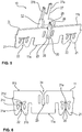
- the Figures 1 and 2 show the stator 1 and a rotor 2 surrounded by it, forming an air gap, as well as a printed circuit board 4 of electronics for controlling an electric motor, in particular an electric bicycle, joined to the stator 1 and contacted with its stator winding 3.
- the stator 1 and the rotor 2 are suitably constructed from stacked individual sheets.
- star-shaped individual laminations are joined on the stator side to form a stator laminated core, which is pressed into a stator yoke 5 likewise suitably packaged from annular laminations.
- the star-shaped laminated core of the stator 1 forms twelve stator teeth 6 which extend radially from the pole piece 7 facing the rotor 2 to the stator yoke 5.
- the rotor 2 is provided with permanent magnets 8, which are inserted into receiving pockets, which are not designated in any more detail, of the laminated rotor core.
- the contacting of the stator winding 3, which comprises a number of coils 9 corresponding to the number of stator teeth 6, is contacted with the circuit board 4 by means of a contact system 10.
- the contact system 10 in the exemplary embodiment comprises three contact element pairs 10a, 10b, 10c for the three-phase stator winding 3 in the exemplary embodiment.
- Each phase is assigned two diametrically opposed coil pairs with a total of four coils 9, which within the respective phase strand in Are connected in series.
- One of the contact element pairs 10a to 10c is assigned to each phase of the stator winding 3.
- Each of the contact element pairs 10a, 10b, 10c comprises according to Figure 4 a first contact element 11 and a second contact element 12.
- the first contact element 11 is seated in a wire guide 13 and there in a tangentially extending plug-in slot 14 that is axially open on one side.
- the respective wire guide 13 is part of an interconnection or end disk, referred to below as an interconnection ring 15, which is located on the end face of the stator 1 facing the printed circuit board 4 above or at the end of the rotor 2.
- this interconnection ring 15 is removed, so that the view of the rotor 2 or its end face is released.
- the respective wire guide 13 has two spaced apart and axially open on one side and essentially radially oriented guide contours 16, 17. These are practically crossed by the tangentially extending slot 14. Axially and radially are to be understood as “running or oriented in the axial direction” or running or oriented in the radial direction " Figure 1 The axial direction A and radial direction R drawn in relation to the motor axis M are shown in FIG Figure 3 illustrated.
- this is the wire section 19 between adjacent coils 9 of two phase strands, the coils 9 of which are connected in a delta connection in the exemplary embodiment.
- the wire section 19 lies in the slot-like guide contours 16, 17 of the wire guide 13.
- the first contact element 11 is inserted into the plug-in slot 14 during assembly, during which an insulation displacement contact is made between the first contact element 11 and the wire section 19, preferably within both guide contours 16 and 17.
- the first contact element 11 has at the two insulation displacement contact points a clamping slot, described in more detail below, for receiving a contact leg 20 of the second contact element 12.
- the second contact element 12 is joined to the printed circuit board 4 and contacted.
- Figure 5 shows such a contact element pair 11, 12 of the contact system 10.
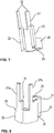
- Figure 6 shows the first contact element 11, while the Figures 7 and 8 show the second contact element 12 in different perspective representations.
- the first contact element 11 has two insulation displacement contacts 21 spaced apart from one another, each with an insulation displacement opening 22. These are located on the underside 11a facing the wire section 19 in the assembled state, with which the first contact element 11 is seated in the plug-in slot 14 of the wire guide 13.
- the clamping slot 23 of the first contact element 11 serving to receive the contact leg 20 of the second contact element 12 also has a clamping slot opening 24 (FIG. 6) located on the opposite top side 11b of the first contact element 11.
- the respective insulation displacement contact 21 is essentially M-shaped with two V-shaped insulation displacement legs 21a, 21b.
- the leg sections 21c and 21d of the V-shaped insulation displacement opening 22 are not connected to one another. Rather, in the exemplary embodiment, these are in contact with one another in the region of the slot base 21e.
- the insulation displacement legs 21a, 21b and thus the respective insulation displacement contacts 21 are in the insulation displacement slot area resilient and can evade in the course of the insulation displacement contact accordingly under spring preload.
- knife-like cutting edges 25 for cutting through the wire insulation of the wire section 19 are formed on the respective insulation displacement legs 21a and 21b.
- the second contact element 12 has the contact leg 20 corresponding to the clamping slot 23 of the first contact element 11 and engaging in this clamping slot 23 and an adjoining spring leg 26 and a plug leg 27 adjoining this in turn.
- this comprises two plug pins 27a and 27b oriented in the axial direction A. In the assembled state, these plug pins 27a, 27b and thus the plug-in legs 27 of the second contact element 12 sit in corresponding through openings in the circuit board 4 and are contacted there on one and / or the other side of the circuit board.
- the spring leg 26 of the second contact element 12 which is semicircular in the exemplary embodiment, forms a resilient area which facilitates the plug-in contact between the first and second contact elements 11, 12 and compensates for any manufacturing tolerances. In addition, this enables operational mechanical vibrations and relative movements between the stator 1 and the printed circuit board 4 to be compensated for in the electric motor operation without impairing the contact between the contact elements 11, 12.
- the second contact element 12 is supported on the printed circuit board 4 via a deliberately raised support surface 28, which is suitably formed on the contact leg 20 on its side facing away from a leg tip 29.
- the contact leg 20 with its leg tip 29 seated in the clamping slot 23 of the first contact element 11 is suitably designed as a blade contact.
- the coils 9 of the stator winding 3 are connected to the two pairs of coils in three phase strands to form a three-phase system in a delta connection.
- the respective wire section 19 connects the transition between one of the coils 9 of a phase line with one of the coils 9 of the further phase line connected in series with it.
- the contact is made by means of the first contact element 11 and the respective phase connection of the stator winding 3 on the one hand and via the corresponding second contact element 12 to the printed circuit board 4 on the other hand.
- the contact system 10 is, however, basically also suitable for realizing a star connection, the wire sections 19 then forming the coil or winding ends of one of the three phase strands connected at the star point with a number of coils 9 connected in series.
- a star point element can, for example, have three insulation displacement terminals with or without spring contacts for contacting electronics or circuit boards.
- first contact element 11 on the stator side can be provided with a knife-like contact leg, while the second contact element 12 on the circuit board side then has the corresponding clamping slot.
- an axial receiving chamber 32 open on one side is provided in the respective wire guide 13 ( Fig. 4 ) brought in. In this protrudes or engages the second clamping element 12 in Fig. 2 shown assembly or joining state of the stator 1 with the circuit board 4 of the motor electronics partially.
Landscapes
- Engineering & Computer Science (AREA)
- Power Engineering (AREA)
- Insulation, Fastening Of Motor, Generator Windings (AREA)
Claims (11)
- Stator (1) d'un moteur électrique, avec un certain nombre de dents de stator (6) portant des bobines (9) d'un enroulement statorique polyphasé (3), et avec un certain nombre de guide-fils (13) du côté pièce pôles avec des premiers éléments de contact (11), qui y sont insérés et qui comportent chacun au moins un contact autodénudant (21), qui comporte une ouverture autodénudante (22), pour un tronçon de fil (19) de bobines (9) reliées entre elles- le premier élément de contact (11) comportant une fente de serrage (23) avec une ouverture de fente de serrage (24), par laquelle un deuxième élément de contact (12) contacté avec une carte de circuit imprimé (4) est inséré ou peut être inséré dans la fente de serrage (23) en établissant un contact par serrage, et- le deuxième élément de contact (12) comporte une branche de contact (20) s'engageant dans la fente de serrage (23) du premier élément de contact (11),caractérisé en ce- que le deuxième élément de contact (12) comporte une branche d'enfichage (27), qui est reliée à sa branche de contact (20) par une branche à ressort (26) et qui est guidée ou peut être guidée dans une ouverture d'enfichage et/ou à un point de contact de la carte de circuit imprimé (4), et- que le guide-fil (13) respectif comporte une chambre de réception (32) ouverte axialement d'un côté, dans laquelle le deuxième élément de contact (12) est partiellement inséré à l'état de montage avec serrage.
- Stator (1) selon la revendication 1,
caractérisé en ce
que l'ouverture de la fente de serrage (24) de la fente de serrage (23) est orientée à l'opposé de l'ouverture de serrage de coupe (22) et cette dernière est orientée vers le tronçon de fil (19) correspondante. - Stator (1) selon la revendication 1 ou 2,
caractérisé en ce
que le premier élément de contact (11) comporte un deuxième contact autodénudant (21) espacé du contact autodénudant (21). - Stator (1) selon l'une des revendications 1 à 3,
caractérisé en ce
que le guide-fil (13) respectif comporte au moins un contour de guidage (16, 17) ouvert axialement sur un côté et orienté essentiellement radialement, dans lequel le tronçon de fil (19) est inséré au moins partiellement. - Stator (1) selon l'une des revendications 1 à 4,
caractérisé en ce
que le guide-fil (13) respectif comporte deux contours de guidage (16, 17) espacés l'un de l'autre, ouverts axialement d'un côté et orientés essentiellement radialement, qui forment une nervure axiale (18) autour de laquelle est placé le tronçon de fil (19). - Stator (1) selon l'une des revendications 1 à 5,
caractérisé en ce
que le guide-fil (13) respectif comporte une fente d'enfichage (14) s'étendant tangentiellement, ouverte axialement sur un côté, dans laquelle le premier élément de contact (11) est logé avec son ouverture de coupe/clampage (22). - Stator (1) selon la revendication 6,
caractérisé en ce
que la profondeur de la fente d'insertion (14) est supérieure ou égale à la hauteur axiale du premier élément de contact (11). - Stator (1) selon l'une des revendications 1 à 7,
caractérisé en
que les guide-fils (13) sont disposés le long d'un arc d'un élément d'interconnexion (15) côte pièce pôle en forme de disque ou d'anneau. - Stator (1) selon l'une des revendications 1 à 8,
caractérisé en ce
que la branche à ressort (26) du deuxième élément de contact (12) est semi-circulaire. - Stator (1) selon l'une des revendications 1 à 9,
caractérisé en ce
que des bornes (30) guidées à travers la carte de circuit imprimé (4) sont prévues à l'extrémité avant de la branche d'enfichage (27) du deuxième élément de contact (12). - Stator (1) selon l'une des revendications précédentes, avec un nombre de guide-fils (13) côté pièce pôle correspondant au nombre de phases, ou un multiple de celui-ci, avec des premiers éléments de contact (11), qui y sont insérés et des deuxièmes éléments de contact (12), qui sont contactés par serrage ou peuvent être contactés par serrage avec ceux-ci.
Applications Claiming Priority (2)
| Application Number | Priority Date | Filing Date | Title |
|---|---|---|---|
| DE202014005789.3U DE202014005789U1 (de) | 2014-07-17 | 2014-07-17 | Stator eines Elektromotors sowie Kontaktsystem hierfür |
| PCT/EP2015/065901 WO2016008827A2 (fr) | 2014-07-17 | 2015-07-10 | Stator d'un moteur électrique et système de contact à cet effet |
Publications (2)
| Publication Number | Publication Date |
|---|---|
| EP3170245A2 EP3170245A2 (fr) | 2017-05-24 |
| EP3170245B1 true EP3170245B1 (fr) | 2021-03-10 |
Family
ID=53762141
Family Applications (1)
| Application Number | Title | Priority Date | Filing Date |
|---|---|---|---|
| EP15744503.2A Active EP3170245B1 (fr) | 2014-07-17 | 2015-07-10 | Stator d'un moteur électrique |
Country Status (3)
| Country | Link |
|---|---|
| EP (1) | EP3170245B1 (fr) |
| DE (1) | DE202014005789U1 (fr) |
| WO (1) | WO2016008827A2 (fr) |
Families Citing this family (7)
| Publication number | Priority date | Publication date | Assignee | Title |
|---|---|---|---|---|
| DE102016107543A1 (de) * | 2016-04-22 | 2017-10-26 | Ebm-Papst Mulfingen Gmbh & Co. Kg | Kontaktierungsanordnung zwischen einem Stator und einer Leiterplatte |
| AT520107A1 (de) * | 2017-07-12 | 2019-01-15 | B & R Ind Automation Gmbh | Montageverfahren für einen Langstatorlinearmotor |
| DE102019104706A1 (de) * | 2019-02-25 | 2020-08-27 | Nidec Gpm Gmbh | Elektrische Kontaktierung von Statoranschlüssen auf einer Leiterplatte mittels horizontal ausgerichteten Schneidklemmkontakten |
| DE102019206641A1 (de) * | 2019-05-08 | 2020-11-12 | Brose Fahrzeugteile SE & Co. Kommanditgesellschaft, Würzburg | Stator eines Elektromotors |
| DE102019116257A1 (de) * | 2019-06-14 | 2020-12-17 | Nidec Gpm Gmbh | Anschlusselement für eine Wicklung eines Stators an einer Leiterplatte mit wenigstens zwei Schneidklemm-Kontakten |
| DE102022200865A1 (de) | 2022-01-26 | 2023-07-27 | Brose Fahrzeugteile SE & Co. Kommanditgesellschaft, Würzburg | Stator eines Elektromotors |
| DE102022213212A1 (de) | 2022-12-07 | 2024-06-13 | Brose Fahrzeugteile SE & Co. Kommanditgesellschaft, Würzburg | Stator eines Elektromotors |
Family Cites Families (7)
| Publication number | Priority date | Publication date | Assignee | Title |
|---|---|---|---|---|
| DE19905948A1 (de) | 1999-02-12 | 2000-08-17 | Wilo Gmbh | Polschenkelträger |
| US7135799B2 (en) * | 2003-03-19 | 2006-11-14 | Pacsci Motion Control, Inc. | Method for winding a stator of multi-phase motors |
| DE10324664A1 (de) * | 2003-05-30 | 2004-12-30 | Siemens Ag | Rollen und Rollenmotoren |
| EP1705775B1 (fr) * | 2005-03-17 | 2006-12-20 | Zf Friedrichshafen Ag | Stator pour machine électrique |
| DK1727261T4 (da) * | 2005-05-23 | 2013-09-30 | Ebm Papst Mulfingen Gmbh & Co | Stator til en elektromotor |
| JP4287418B2 (ja) * | 2005-09-02 | 2009-07-01 | 本田技研工業株式会社 | モータの結線構造 |
| DE102007058243A1 (de) * | 2007-12-04 | 2009-06-10 | Robert Bosch Gmbh | Anschlusselement und zugehöriges Fluidbaugruppe |
-
2014
- 2014-07-17 DE DE202014005789.3U patent/DE202014005789U1/de not_active Expired - Lifetime
-
2015
- 2015-07-10 WO PCT/EP2015/065901 patent/WO2016008827A2/fr active Application Filing
- 2015-07-10 EP EP15744503.2A patent/EP3170245B1/fr active Active
Non-Patent Citations (1)
| Title |
|---|
| None * |
Also Published As
| Publication number | Publication date |
|---|---|
| WO2016008827A2 (fr) | 2016-01-21 |
| EP3170245A2 (fr) | 2017-05-24 |
| WO2016008827A3 (fr) | 2016-07-21 |
| DE202014005789U1 (de) | 2015-10-23 |
Similar Documents
| Publication | Publication Date | Title |
|---|---|---|
| EP3170245B1 (fr) | Stator d'un moteur électrique | |
| EP2082472B1 (fr) | Moteur électrique | |
| EP3402047B1 (fr) | Contact pénétrant l'isolation | |
| EP2959564B1 (fr) | Moteur électrique, notamment d'un composant de véhicule | |
| DE102015200089B4 (de) | Stator für eine elektrische Maschine und Verfahren zum Herstellen eines solchen | |
| EP3320600B1 (fr) | Arrangement de stator, machine électrique à courant triphasé et procédé de fabrication d'un arrangement de stator | |
| WO2018104418A1 (fr) | Stator d'une machine électrique, machine électrique et dispositif de transfert et de contact pour une machine électrique | |
| DE102012113095B4 (de) | Bürstenloser Motor | |
| DE202015008207U1 (de) | Stator eines Elektromotors sowie Schalteinheit hierfür | |
| DE102017211392A1 (de) | Stator für einen Elektromotor und Elektromotor | |
| DE102019004591A1 (de) | Elektromotor mit einer Verschaltungseinheit und Verfahren zur Herstellung eines Elektromotors mit einer Verschaltungseinheit | |
| DE102020115642B3 (de) | Elektrischer Motor und Leiterplatte | |
| EP1024581B1 (fr) | Connexions des enroulements d'un moteur | |
| EP3824530B1 (fr) | Moteur électrique comprenant une unité de câblage | |
| WO2019215031A1 (fr) | Stator d'une machine électrique, machine électrique et équipement de connexion | |
| DE102018116930A1 (de) | Stator für eine Gleichstrommaschine und Verfahren zum Herstellen eines solchen Stators | |
| EP3128650A1 (fr) | Machine électrique à courant continu et procédé de fabrication d'une machine électrique à courant continu | |
| WO2020173913A1 (fr) | Mise en contact électrique de bornes de stator sur une carte de circuit imprimé au moyen de contacts à borne guillotine orientés horizontalement | |
| DE102019004590A1 (de) | Elektromotor mit einer Verschaltungseinheit und Verfahren zur Herstellung eines Elektromotors mit einer Verschaltungseinheit | |
| DE102023123344A1 (de) | Motor und drohne | |
| DE102022200865A1 (de) | Stator eines Elektromotors | |
| DE102021214766A1 (de) | Stator für eine elektrische Maschine, eine elektrische Maschine und Verfahren zum Herstellen eines solchen Stators | |
| DE102021004542A1 (de) | Elktromotor mit einer Verschaltungseinheit und einem Stator sowie Verfahren zur Herstellung eines solchen Elektromotors |
Legal Events
| Date | Code | Title | Description |
|---|---|---|---|
| STAA | Information on the status of an ep patent application or granted ep patent |
Free format text: STATUS: THE INTERNATIONAL PUBLICATION HAS BEEN MADE |
|
| PUAI | Public reference made under article 153(3) epc to a published international application that has entered the european phase |
Free format text: ORIGINAL CODE: 0009012 |
|
| STAA | Information on the status of an ep patent application or granted ep patent |
Free format text: STATUS: REQUEST FOR EXAMINATION WAS MADE |
|
| 17P | Request for examination filed |
Effective date: 20170217 |
|
| AK | Designated contracting states |
Kind code of ref document: A2 Designated state(s): AL AT BE BG CH CY CZ DE DK EE ES FI FR GB GR HR HU IE IS IT LI LT LU LV MC MK MT NL NO PL PT RO RS SE SI SK SM TR |
|
| AX | Request for extension of the european patent |
Extension state: BA ME |
|
| RIN1 | Information on inventor provided before grant (corrected) |
Inventor name: NOACK, ULRICH Inventor name: MISCH, ROMAN Inventor name: GORNOTT, ANDRE Inventor name: JORDAN, IVONNE |
|
| DAV | Request for validation of the european patent (deleted) | ||
| DAX | Request for extension of the european patent (deleted) | ||
| STAA | Information on the status of an ep patent application or granted ep patent |
Free format text: STATUS: EXAMINATION IS IN PROGRESS |
|
| 17Q | First examination report despatched |
Effective date: 20190513 |
|
| RAP1 | Party data changed (applicant data changed or rights of an application transferred) |
Owner name: BROSE FAHRZEUGTEILE SE & CO. KOMMANDITGESELLSCHAFT, COBURG |
|
| APBK | Appeal reference recorded |
Free format text: ORIGINAL CODE: EPIDOSNREFNE |
|
| APBN | Date of receipt of notice of appeal recorded |
Free format text: ORIGINAL CODE: EPIDOSNNOA2E |
|
| APBR | Date of receipt of statement of grounds of appeal recorded |
Free format text: ORIGINAL CODE: EPIDOSNNOA3E |
|
| APBV | Interlocutory revision of appeal recorded |
Free format text: ORIGINAL CODE: EPIDOSNIRAPE |
|
| GRAP | Despatch of communication of intention to grant a patent |
Free format text: ORIGINAL CODE: EPIDOSNIGR1 |
|
| STAA | Information on the status of an ep patent application or granted ep patent |
Free format text: STATUS: GRANT OF PATENT IS INTENDED |
|
| RIN1 | Information on inventor provided before grant (corrected) |
Inventor name: MISCH, ROMAN Inventor name: JORDAN, IVONNE Inventor name: NOACK, ULRICH Inventor name: GORNOTT, ANDRE |
|
| INTG | Intention to grant announced |
Effective date: 20201019 |
|
| GRAS | Grant fee paid |
Free format text: ORIGINAL CODE: EPIDOSNIGR3 |
|
| GRAA | (expected) grant |
Free format text: ORIGINAL CODE: 0009210 |
|
| STAA | Information on the status of an ep patent application or granted ep patent |
Free format text: STATUS: THE PATENT HAS BEEN GRANTED |
|
| AK | Designated contracting states |
Kind code of ref document: B1 Designated state(s): AL AT BE BG CH CY CZ DE DK EE ES FI FR GB GR HR HU IE IS IT LI LT LU LV MC MK MT NL NO PL PT RO RS SE SI SK SM TR |
|
| REG | Reference to a national code |
Ref country code: GB Ref legal event code: FG4D Free format text: NOT ENGLISH |
|
| REG | Reference to a national code |
Ref country code: AT Ref legal event code: REF Ref document number: 1370898 Country of ref document: AT Kind code of ref document: T Effective date: 20210315 Ref country code: CH Ref legal event code: EP |
|
| REG | Reference to a national code |
Ref country code: DE Ref legal event code: R096 Ref document number: 502015014383 Country of ref document: DE |
|
| REG | Reference to a national code |
Ref country code: IE Ref legal event code: FG4D Free format text: LANGUAGE OF EP DOCUMENT: GERMAN |
|
| REG | Reference to a national code |
Ref country code: LT Ref legal event code: MG9D |
|
| PG25 | Lapsed in a contracting state [announced via postgrant information from national office to epo] |
Ref country code: LT Free format text: LAPSE BECAUSE OF FAILURE TO SUBMIT A TRANSLATION OF THE DESCRIPTION OR TO PAY THE FEE WITHIN THE PRESCRIBED TIME-LIMIT Effective date: 20210310 Ref country code: GR Free format text: LAPSE BECAUSE OF FAILURE TO SUBMIT A TRANSLATION OF THE DESCRIPTION OR TO PAY THE FEE WITHIN THE PRESCRIBED TIME-LIMIT Effective date: 20210611 Ref country code: HR Free format text: LAPSE BECAUSE OF FAILURE TO SUBMIT A TRANSLATION OF THE DESCRIPTION OR TO PAY THE FEE WITHIN THE PRESCRIBED TIME-LIMIT Effective date: 20210310 Ref country code: FI Free format text: LAPSE BECAUSE OF FAILURE TO SUBMIT A TRANSLATION OF THE DESCRIPTION OR TO PAY THE FEE WITHIN THE PRESCRIBED TIME-LIMIT Effective date: 20210310 Ref country code: BG Free format text: LAPSE BECAUSE OF FAILURE TO SUBMIT A TRANSLATION OF THE DESCRIPTION OR TO PAY THE FEE WITHIN THE PRESCRIBED TIME-LIMIT Effective date: 20210610 Ref country code: NO Free format text: LAPSE BECAUSE OF FAILURE TO SUBMIT A TRANSLATION OF THE DESCRIPTION OR TO PAY THE FEE WITHIN THE PRESCRIBED TIME-LIMIT Effective date: 20210610 |
|
| REG | Reference to a national code |
Ref country code: NL Ref legal event code: MP Effective date: 20210310 |
|
| PG25 | Lapsed in a contracting state [announced via postgrant information from national office to epo] |
Ref country code: RS Free format text: LAPSE BECAUSE OF FAILURE TO SUBMIT A TRANSLATION OF THE DESCRIPTION OR TO PAY THE FEE WITHIN THE PRESCRIBED TIME-LIMIT Effective date: 20210310 Ref country code: LV Free format text: LAPSE BECAUSE OF FAILURE TO SUBMIT A TRANSLATION OF THE DESCRIPTION OR TO PAY THE FEE WITHIN THE PRESCRIBED TIME-LIMIT Effective date: 20210310 Ref country code: SE Free format text: LAPSE BECAUSE OF FAILURE TO SUBMIT A TRANSLATION OF THE DESCRIPTION OR TO PAY THE FEE WITHIN THE PRESCRIBED TIME-LIMIT Effective date: 20210310 |
|
| PG25 | Lapsed in a contracting state [announced via postgrant information from national office to epo] |
Ref country code: NL Free format text: LAPSE BECAUSE OF FAILURE TO SUBMIT A TRANSLATION OF THE DESCRIPTION OR TO PAY THE FEE WITHIN THE PRESCRIBED TIME-LIMIT Effective date: 20210310 |
|
| PG25 | Lapsed in a contracting state [announced via postgrant information from national office to epo] |
Ref country code: SM Free format text: LAPSE BECAUSE OF FAILURE TO SUBMIT A TRANSLATION OF THE DESCRIPTION OR TO PAY THE FEE WITHIN THE PRESCRIBED TIME-LIMIT Effective date: 20210310 Ref country code: EE Free format text: LAPSE BECAUSE OF FAILURE TO SUBMIT A TRANSLATION OF THE DESCRIPTION OR TO PAY THE FEE WITHIN THE PRESCRIBED TIME-LIMIT Effective date: 20210310 Ref country code: CZ Free format text: LAPSE BECAUSE OF FAILURE TO SUBMIT A TRANSLATION OF THE DESCRIPTION OR TO PAY THE FEE WITHIN THE PRESCRIBED TIME-LIMIT Effective date: 20210310 |
|
| PG25 | Lapsed in a contracting state [announced via postgrant information from national office to epo] |
Ref country code: IS Free format text: LAPSE BECAUSE OF FAILURE TO SUBMIT A TRANSLATION OF THE DESCRIPTION OR TO PAY THE FEE WITHIN THE PRESCRIBED TIME-LIMIT Effective date: 20210710 Ref country code: ES Free format text: LAPSE BECAUSE OF FAILURE TO SUBMIT A TRANSLATION OF THE DESCRIPTION OR TO PAY THE FEE WITHIN THE PRESCRIBED TIME-LIMIT Effective date: 20210310 Ref country code: PL Free format text: LAPSE BECAUSE OF FAILURE TO SUBMIT A TRANSLATION OF THE DESCRIPTION OR TO PAY THE FEE WITHIN THE PRESCRIBED TIME-LIMIT Effective date: 20210310 Ref country code: PT Free format text: LAPSE BECAUSE OF FAILURE TO SUBMIT A TRANSLATION OF THE DESCRIPTION OR TO PAY THE FEE WITHIN THE PRESCRIBED TIME-LIMIT Effective date: 20210712 Ref country code: SK Free format text: LAPSE BECAUSE OF FAILURE TO SUBMIT A TRANSLATION OF THE DESCRIPTION OR TO PAY THE FEE WITHIN THE PRESCRIBED TIME-LIMIT Effective date: 20210310 Ref country code: RO Free format text: LAPSE BECAUSE OF FAILURE TO SUBMIT A TRANSLATION OF THE DESCRIPTION OR TO PAY THE FEE WITHIN THE PRESCRIBED TIME-LIMIT Effective date: 20210310 |
|
| REG | Reference to a national code |
Ref country code: DE Ref legal event code: R097 Ref document number: 502015014383 Country of ref document: DE |
|
| PLBE | No opposition filed within time limit |
Free format text: ORIGINAL CODE: 0009261 |
|
| STAA | Information on the status of an ep patent application or granted ep patent |
Free format text: STATUS: NO OPPOSITION FILED WITHIN TIME LIMIT |
|
| PG25 | Lapsed in a contracting state [announced via postgrant information from national office to epo] |
Ref country code: DK Free format text: LAPSE BECAUSE OF FAILURE TO SUBMIT A TRANSLATION OF THE DESCRIPTION OR TO PAY THE FEE WITHIN THE PRESCRIBED TIME-LIMIT Effective date: 20210310 Ref country code: AL Free format text: LAPSE BECAUSE OF FAILURE TO SUBMIT A TRANSLATION OF THE DESCRIPTION OR TO PAY THE FEE WITHIN THE PRESCRIBED TIME-LIMIT Effective date: 20210310 |
|
| 26N | No opposition filed |
Effective date: 20211213 |
|
| PG25 | Lapsed in a contracting state [announced via postgrant information from national office to epo] |
Ref country code: SI Free format text: LAPSE BECAUSE OF FAILURE TO SUBMIT A TRANSLATION OF THE DESCRIPTION OR TO PAY THE FEE WITHIN THE PRESCRIBED TIME-LIMIT Effective date: 20210310 |
|
| REG | Reference to a national code |
Ref country code: CH Ref legal event code: PL |
|
| PG25 | Lapsed in a contracting state [announced via postgrant information from national office to epo] |
Ref country code: MC Free format text: LAPSE BECAUSE OF FAILURE TO SUBMIT A TRANSLATION OF THE DESCRIPTION OR TO PAY THE FEE WITHIN THE PRESCRIBED TIME-LIMIT Effective date: 20210310 |
|
| REG | Reference to a national code |
Ref country code: BE Ref legal event code: MM Effective date: 20210731 |
|
| PG25 | Lapsed in a contracting state [announced via postgrant information from national office to epo] |
Ref country code: LI Free format text: LAPSE BECAUSE OF NON-PAYMENT OF DUE FEES Effective date: 20210731 Ref country code: IT Free format text: LAPSE BECAUSE OF FAILURE TO SUBMIT A TRANSLATION OF THE DESCRIPTION OR TO PAY THE FEE WITHIN THE PRESCRIBED TIME-LIMIT Effective date: 20210310 Ref country code: CH Free format text: LAPSE BECAUSE OF NON-PAYMENT OF DUE FEES Effective date: 20210731 |
|
| PG25 | Lapsed in a contracting state [announced via postgrant information from national office to epo] |
Ref country code: IS Free format text: LAPSE BECAUSE OF FAILURE TO SUBMIT A TRANSLATION OF THE DESCRIPTION OR TO PAY THE FEE WITHIN THE PRESCRIBED TIME-LIMIT Effective date: 20210710 Ref country code: LU Free format text: LAPSE BECAUSE OF NON-PAYMENT OF DUE FEES Effective date: 20210710 |
|
| PG25 | Lapsed in a contracting state [announced via postgrant information from national office to epo] |
Ref country code: IE Free format text: LAPSE BECAUSE OF NON-PAYMENT OF DUE FEES Effective date: 20210710 Ref country code: BE Free format text: LAPSE BECAUSE OF NON-PAYMENT OF DUE FEES Effective date: 20210731 |
|
| REG | Reference to a national code |
Ref country code: AT Ref legal event code: MM01 Ref document number: 1370898 Country of ref document: AT Kind code of ref document: T Effective date: 20210710 |
|
| PG25 | Lapsed in a contracting state [announced via postgrant information from national office to epo] |
Ref country code: AT Free format text: LAPSE BECAUSE OF NON-PAYMENT OF DUE FEES Effective date: 20210710 |
|
| PG25 | Lapsed in a contracting state [announced via postgrant information from national office to epo] |
Ref country code: HU Free format text: LAPSE BECAUSE OF FAILURE TO SUBMIT A TRANSLATION OF THE DESCRIPTION OR TO PAY THE FEE WITHIN THE PRESCRIBED TIME-LIMIT; INVALID AB INITIO Effective date: 20150710 |
|
| PG25 | Lapsed in a contracting state [announced via postgrant information from national office to epo] |
Ref country code: CY Free format text: LAPSE BECAUSE OF FAILURE TO SUBMIT A TRANSLATION OF THE DESCRIPTION OR TO PAY THE FEE WITHIN THE PRESCRIBED TIME-LIMIT Effective date: 20210310 |
|
| P01 | Opt-out of the competence of the unified patent court (upc) registered |
Effective date: 20230803 |
|
| PG25 | Lapsed in a contracting state [announced via postgrant information from national office to epo] |
Ref country code: MK Free format text: LAPSE BECAUSE OF FAILURE TO SUBMIT A TRANSLATION OF THE DESCRIPTION OR TO PAY THE FEE WITHIN THE PRESCRIBED TIME-LIMIT Effective date: 20210310 |
|
| PGFP | Annual fee paid to national office [announced via postgrant information from national office to epo] |
Ref country code: GB Payment date: 20240530 Year of fee payment: 10 |
|
| PGFP | Annual fee paid to national office [announced via postgrant information from national office to epo] |
Ref country code: FR Payment date: 20240611 Year of fee payment: 10 |
|
| PG25 | Lapsed in a contracting state [announced via postgrant information from national office to epo] |
Ref country code: MT Free format text: LAPSE BECAUSE OF FAILURE TO SUBMIT A TRANSLATION OF THE DESCRIPTION OR TO PAY THE FEE WITHIN THE PRESCRIBED TIME-LIMIT Effective date: 20210310 |
|
| PGFP | Annual fee paid to national office [announced via postgrant information from national office to epo] |
Ref country code: DE Payment date: 20240731 Year of fee payment: 10 |