EP3169569B1 - Bremsflüssigkeitsbehälter - Google Patents
Bremsflüssigkeitsbehälter Download PDFInfo
- Publication number
- EP3169569B1 EP3169569B1 EP15753903.2A EP15753903A EP3169569B1 EP 3169569 B1 EP3169569 B1 EP 3169569B1 EP 15753903 A EP15753903 A EP 15753903A EP 3169569 B1 EP3169569 B1 EP 3169569B1
- Authority
- EP
- European Patent Office
- Prior art keywords
- brake fluid
- sleeve
- fluid reservoir
- reservoir according
- valve
- Prior art date
- Legal status (The legal status is an assumption and is not a legal conclusion. Google has not performed a legal analysis and makes no representation as to the accuracy of the status listed.)
- Active
Links
Images
Classifications
-
- B—PERFORMING OPERATIONS; TRANSPORTING
- B60—VEHICLES IN GENERAL
- B60T—VEHICLE BRAKE CONTROL SYSTEMS OR PARTS THEREOF; BRAKE CONTROL SYSTEMS OR PARTS THEREOF, IN GENERAL; ARRANGEMENT OF BRAKING ELEMENTS ON VEHICLES IN GENERAL; PORTABLE DEVICES FOR PREVENTING UNWANTED MOVEMENT OF VEHICLES; VEHICLE MODIFICATIONS TO FACILITATE COOLING OF BRAKES
- B60T11/00—Transmitting braking action from initiating means to ultimate brake actuator without power assistance or drive or where such assistance or drive is irrelevant
- B60T11/10—Transmitting braking action from initiating means to ultimate brake actuator without power assistance or drive or where such assistance or drive is irrelevant transmitting by fluid means, e.g. hydraulic
- B60T11/16—Master control, e.g. master cylinders
- B60T11/22—Master control, e.g. master cylinders characterised by being integral with reservoir
-
- B—PERFORMING OPERATIONS; TRANSPORTING
- B60—VEHICLES IN GENERAL
- B60T—VEHICLE BRAKE CONTROL SYSTEMS OR PARTS THEREOF; BRAKE CONTROL SYSTEMS OR PARTS THEREOF, IN GENERAL; ARRANGEMENT OF BRAKING ELEMENTS ON VEHICLES IN GENERAL; PORTABLE DEVICES FOR PREVENTING UNWANTED MOVEMENT OF VEHICLES; VEHICLE MODIFICATIONS TO FACILITATE COOLING OF BRAKES
- B60T11/00—Transmitting braking action from initiating means to ultimate brake actuator without power assistance or drive or where such assistance or drive is irrelevant
- B60T11/10—Transmitting braking action from initiating means to ultimate brake actuator without power assistance or drive or where such assistance or drive is irrelevant transmitting by fluid means, e.g. hydraulic
- B60T11/26—Reservoirs
-
- B—PERFORMING OPERATIONS; TRANSPORTING
- B60—VEHICLES IN GENERAL
- B60T—VEHICLE BRAKE CONTROL SYSTEMS OR PARTS THEREOF; BRAKE CONTROL SYSTEMS OR PARTS THEREOF, IN GENERAL; ARRANGEMENT OF BRAKING ELEMENTS ON VEHICLES IN GENERAL; PORTABLE DEVICES FOR PREVENTING UNWANTED MOVEMENT OF VEHICLES; VEHICLE MODIFICATIONS TO FACILITATE COOLING OF BRAKES
- B60T11/00—Transmitting braking action from initiating means to ultimate brake actuator without power assistance or drive or where such assistance or drive is irrelevant
- B60T11/10—Transmitting braking action from initiating means to ultimate brake actuator without power assistance or drive or where such assistance or drive is irrelevant transmitting by fluid means, e.g. hydraulic
- B60T11/28—Valves specially adapted therefor
-
- B—PERFORMING OPERATIONS; TRANSPORTING
- B60—VEHICLES IN GENERAL
- B60T—VEHICLE BRAKE CONTROL SYSTEMS OR PARTS THEREOF; BRAKE CONTROL SYSTEMS OR PARTS THEREOF, IN GENERAL; ARRANGEMENT OF BRAKING ELEMENTS ON VEHICLES IN GENERAL; PORTABLE DEVICES FOR PREVENTING UNWANTED MOVEMENT OF VEHICLES; VEHICLE MODIFICATIONS TO FACILITATE COOLING OF BRAKES
- B60T17/00—Component parts, details, or accessories of power brake systems not covered by groups B60T8/00, B60T13/00 or B60T15/00, or presenting other characteristic features
- B60T17/06—Applications or arrangements of reservoirs
-
- B—PERFORMING OPERATIONS; TRANSPORTING
- B60—VEHICLES IN GENERAL
- B60T—VEHICLE BRAKE CONTROL SYSTEMS OR PARTS THEREOF; BRAKE CONTROL SYSTEMS OR PARTS THEREOF, IN GENERAL; ARRANGEMENT OF BRAKING ELEMENTS ON VEHICLES IN GENERAL; PORTABLE DEVICES FOR PREVENTING UNWANTED MOVEMENT OF VEHICLES; VEHICLE MODIFICATIONS TO FACILITATE COOLING OF BRAKES
- B60T17/00—Component parts, details, or accessories of power brake systems not covered by groups B60T8/00, B60T13/00 or B60T15/00, or presenting other characteristic features
- B60T17/18—Safety devices; Monitoring
Definitions
- the invention relates to a brake fluid container for a master brake cylinder of a hydraulic brake system, with a container base, a nozzle protruding from the outside of the container base, which is provided for insertion into a receptacle of a master brake cylinder, a safety valve being arranged in the nozzle, the valve closing body of which interacts with the receptacle that the safety valve is open when the nozzle is inserted into the receptacle and is closed when the nozzle is outside the receptacle.
- Such safety valves are used to ensure that from the container when this z. B. as a result of a crash from the master cylinder, no brake fluid escapes, which could ignite on hot engine parts.
- a slit valve is known, the sealing plug having an elastomeric slotted membrane which covers the opening of the container neck.
- a pin-shaped support element is formed on the membrane, which, when installed, is supported on the bottom of the receptacle and thereby opens the slot.
- a safety valve is known from practice, the valve seat of which is formed as part of the container base, so that the assembly of the valve closing body is relatively complex since it is located inside the container.
- the container can be manufactured independently of this cartridge and the cartridge can be preassembled independently of the container.
- the pre-assembled cartridge can then be inserted into the nozzle, preferably into the end of the nozzle that is removed from the container.
- the cartridge preferably consists of a sleeve, on the outer circumferential surface of which means are provided in order to keep it pressure-tight in the socket.
- connection that ensures that the sleeve used is pressure-tight in the connection piece is conceivable, therefore it can be a screw connection, a welded connection, a snap connection or the like.
- the outward-facing end face can be funnel-shaped and flare outward.
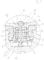
- a cartridge 6 with a safety valve 7 is located within the nozzle 3.
- the cartridge 6 consists of a sleeve 8, the outer diameter of which essentially corresponds to the inner diameter of the nozzle 3.
- the sleeve 8 has on its outer edge a circumferential bead 9 which seals the inner surface of the nozzle 3.
- a radial extension 20 At the lower end of the shaft there is a radial extension 20, the upward end face of which serves as a counter stop surface for the valve spring 13, which extends coaxially to the shaft 17 between the stop surface on the collar 12 of the sleeve and the extension 20 of the shaft 17 and so is biased that it presses the shaft 17 downward, so that the head 16 with the sealing element 19 lies against the valve seat surface 14 in order to close the safety valve 7.
Landscapes
- Engineering & Computer Science (AREA)
- Transportation (AREA)
- Mechanical Engineering (AREA)
- Transmission Of Braking Force In Braking Systems (AREA)
Description
- Die Erfindung bezieht sich auf einen Bremsflüssigkeitsbehälter für einen Hauptbremszylinder einer hydraulischen Bremsanlage, mit einem Behälterboden, einem gegenüber der Außenseite des Behälterbodens vorstehenden Stutzen, der zur Einführung in eine Aufnahme eines Hauptbremszylinders vorgesehen ist, wobei in dem Stutzen ein Sicherheitsventil angeordnet ist, dessen Ventilschließkörper derart mit der Aufnahme zusammenwirkt, dass das Sicherheitsventil geöffnet ist, wenn der Stutzen in die Aufnahme eingeführt ist, und geschlossen ist, wenn der Stutzen sich außerhalb der Aufnahme befindet.
- Derartige Sicherheitsventile werden eingesetzt, um sicher zu stellen, dass aus dem Behälter, wenn dieser sich z. B. in Folge eines Crashs vom Hauptbremszylinder löst, keine Bremsflüssigkeit austritt, die sich ggf. an heißen Motorteilen entzünden könnte. Beispielsweise aus
EP 2 216 220 A1 ist ein Schlitzventil bekannt, wobei der Dichtstopfen eine elastomere eingeschlitzte Membrane aufweist, welche die Öffnung des Behälterstutzens überdeckt. An der Membrane ist ein stiftförmiges Stützelement angeformt, welches im eingebauten Zustand sich am Boden der Aufnahme abstützt und dadurch den Schlitz öffnet. - Aus Praxis ist ein Sicherheitsventil bekannt, dessen Ventilsitz als Teil des Behälterbodens ausgebildet, so dass die Montage des Ventilschließkörpers relativ aufwändig ist, da dieser sich innerhalb des Behälters befindet.
- Es wurde auch schon vorgeschlagen, einen Teil des Bodens mit dem Stutzen, an dem das Ventil montiert wurde, später durch Warmumformung in eine entsprechende Öffnung im Behälterboden zu platzieren.
- Die Erfindung beruht daher auf der Aufgabe, die Montage eines Sicherheitsventils an einem Behälter zu vereinfachen, insbesondere soll die nachträgliche Montage in einen bereits vorhandenen Behälter ohne Werkzeuganpassungen des Behälters möglich sein.
- Zur Lösung des Problems sieht die Erfindung vor, dass das Sicherheitsventil in einer Kartusche angeordnet ist, die in den Stutzen eingesetzt ist.
- Dies hat zur Folge, dass der Behälter unabhängig von dieser Kartusche gefertigt und die Kartusche unabhängig vom Behälter vormontiert werden können. Die vormontierte Kartusche kann dann in den Stutzen eingeschoben werden und zwar vorzugsweise in das Ende des Stutzens, der vom Behälter entfernt ist.
- Dabei kann die Kartusche derart ausgelegt werden, dass sie auch als Nachrüstsatz für bestehende Behälter, zum einschieben in den Stutzen beispielsweise bei Servicearbeiten vorgesehen ist.
- Dazu besteht die Kartusche vorzugsweise aus einer Hülse, an deren Außenmantelfläche Mittel vorhanden sind, um diese druckmitteldicht in dem Stutzen zu halten.
- Jede Verbindung, die sicherstellt, dass die eingesetzte Hülse sich druckmitteldicht in dem Stutzen befindet, ist denkbar, daher kann es sich um eine Schraubverbindung, eine Schweißverbindung, eine Schnappverbindung oder dergleichen handeln.
- Vorzugsweise ist an der Außenmantelfläche ein umlaufender Wulst vorgesehen, der in die Innenmantelfläche des Stutzens eingepresst wird.
- Zur Ausbildung des Sicherheitsventils besitzt die Hülse an ihrem dem Behälter zugewandten Ende einen nach innen gerichteten umlaufenden Kragen, dessen nach innen in die Hülse gerichtete Stirnfläche als Anschlagfläche für eine Ventilfeder dient und dessen nach außen gerichtete Stirnfläche als Ventilsitzfläche dient.
- Die die Ventilsitzfläche bildende, nach außen gerichtete Stirnfläche kann eben sein und senkrecht zur Achse der Hülse verlaufen.
- Alternativ kann die nach außen gerichtete Stirnfläche trichterförmig ausgebildet sein und sich nach außen konisch erweitern.
- Der Ventilschließkörper besitzt einen Kopf, der sich außerhalb der Hülse vor der Ventilsitzfläche befindet, und an dessen Außenrand sich ein Dichtelement befindet.
- Zum Betätigen des Ventils schließt an den Kopf ein Schaft an, der durch die Hülse hindurchgeführt ist und dessen unteres Ende in einem Stößel endet.
- In seinem mittleren Bereich weist der Schaft eine radiale Erweiterung auf, deren nach innen in die Hülse gerichtete Stirnfläche als Gegenanschlagsfläche für die Feder dient.
- Damit zwischen Schaft und Hülse ein ausreichender Durchfluss realisiert ist, kann die Erweiterung an ihrer Außenwand mit Ausnehmungen versehen sein.
- Im Folgenden wird anhand eines Ausführungsbeispiels die Erfindung in einer einzigen Figur näher erläutert:
Diese zeigt in einem Schnitt die Aufnahme 1 eines Hauptbremszylinders 2, in dem der Stutzen 3 eines Bremsflüssigkeitsbehälters 4, im Folgenden nur kurz "Behälter" genannt, eingesteckt ist und von einem Behälterstopfen 5 gehalten wird. - Innerhalb des Stutzens 3 befindet sich eine Kartusche 6 mit einem Sicherheitsventil 7. Die Kartusche 6 besteht aus einer Hülse 8, dessen Außendurchmesser im Wesentlichen dem Innendurchmesser des Stutzens 3 entspricht. Um eine druckmitteldichte Verbindung zu erhalten, besitzt die Hülse 8 an ihrem Außenrand einen umlaufenden Wulst 9, der die Innenmantelfläche des Stutzens 3 abdichtet.
- Am unteren Ende der Hülse 8, das zum Hauptbremszylinder 2 weist, befindet sich ein umlaufender Flansch 11, der als Anschlag dient, wenn die Hülse 8 von unten in den Stutzen 3 eingeschoben wird.
- Am oberen Ende der Hülse befindet sich ein nach innen gerichteter umlaufender Kragen 12, dessen nach unten gerichtete Stirnfläche als Anschlag für eine Ventilfeder 13 dient und dessen nach oben gerichtete Stirnfläche trichterförmig ausgebildet ist, sich nach oben konisch erweitert und als Ventilsitzfläche 14 dient.
- Durch die Hülse 8 erstreckt sich ein Ventilschließkörper 15, bestehend aus einem Kopf 16 und einem Schaft 17, der sich in axialer Richtung an den Kopf 16 anschließt und der an seinem unteren Ende in einem Stößel 18 endet.
- Der Kopf 16 besitzt ein in einer Nut liegendes umlaufendes Dichtelement 19, das der Ventilsitzfläche 14 gegenüberliegt und das die Form eines Dichtringes hat.
- Am unteren Ende des Schaftes befindet sich eine radiale Erweiterung 20, deren nach oben gerichtete Stirnfläche als Gegenanschlagsfläche für die Ventilfeder 13 dient, die sich koaxial zum Schaft 17 zwischen der Anschlagfläche am Kragen 12 der Hülse und der Erweiterung 20 des Schaftes 17 erstreckt und die so vorgespannt ist, dass sie den Schaft 17 nach unten drückt, so dass sich der Kopf 16 mit dem Dichtelement 19 gegen die Ventilsitzfläche 14 legt, um das Sicherheitsventil 7 zu schließen.
- In dem hier eingebauten Zustand wird dies dadurch verhindert, dass der Stößel 18 am Boden der Aufnahme 1 anliegt, und damit den Kopf 16 gegen den Druck der Ventilfeder 13 von der Ventilsitzfläche 14 entfernt hält. Sollte der Behälter 4 z. B. unfallbedingt aus dem Stutzen 3 entfernt werden, fehlt diese Gegenkraft, so dass das Sicherheitsventil 7 schließt.
-
- 1
- Aufnahme
- 2
- Hauptbremszylinder
- 3
- Stutzen
- 4
- Behälter
- 5
- Behälterstopfen
- 6
- Kartusche
- 7
- Sicherheitsventil
- 8
- Hülse
- 9
- Wulst
- 10
- -
- 11
- Flansch
- 12
- Kragen
- 13
- Ventilfeder
- 14
- Ventilsitzfläche
- 15
- Ventilschließkörper
- 16
- Kopf
- 17
- Schaft
- 18
- Stößel
- 19
- Dichtelement
- 20
- Erweiterung
Claims (10)
- Bremsflüssigkeitsbehälter (4) für einen Hauptbremszylinder (2) einer hydraulischen Bremsanlage, mit einem Behälterboden, einem gegenüber einer Außenseite des Behälterbodens vorstehenden Stutzen (3), der zur Einführung in eine Aufnahme (1) des Hauptbremszylinders (2) vorgesehen ist, wobei in dem Stutzen (3) ein Sicherheitsventil (7) angeordnet ist, dessen Ventilschließkörper (15) derart mit der Aufnahme (1) zusammenwirkt, dass das Sicherheitsventil (7) geöffnet ist, wenn der Stutzen (3) in die Aufnahme (1) eingeführt ist, und geschlossen ist, wenn der Stutzen (3) sich außerhalb der Aufnahme (1) befindet, dadurch gekennzeichnet, dass das Sicherheitsventil (7) in einer Kartusche (6) angeordnet ist, die in den Stutzen (3) eingesetzt ist.
- Bremsflüssigkeitsbehälter nach Anspruch 1, dadurch gekennzeichnet, dass die Kartusche (6) aus einer Hülse (8) besteht, an deren Außenmantelfläche Mittel vorhanden sind, um diese druckmitteldicht in dem Stutzen (3) zu halten.
- Bremsflüssigkeitsbehälter nach Anspruch 2, dadurch gekennzeichnet, dass an der Außenmantelfläche der Hülse (8) ein umlaufender Wulst (9) vorgesehen ist, der in die Innenmantelfläche des Stutzens eingepresst wird.
- Bremsflüssigkeitsbehälter nach einem der vorhergehende Ansprüche, dadurch gekennzeichnet, dass zur Ausbildung des Sicherheitsventils (7) die Hülse (8) an ihrem dem Behälter (4) zugewandten Ende einen nach innen gerichteten umlaufenden Kragen (12) besitzt, dessen nach innen in die Hülse gerichtete Stirnfläche als Anschlagfläche für eine Ventilfeder (13) dient und dessen nach außen gerichtete Stirnfläche als Ventilsitzfläche (14) dient.
- Bremsflüssigkeitsbehälter nach Anspruch 4, dadurch gekennzeichnet, dass die nach außen gerichtete Stirnfläche eben ist und senkrecht zur Achse der Hülse (8) verläuft.
- Bremsflüssigkeitsbehälter nach Anspruch 4, dadurch gekennzeichnet, dass die nach außen gerichtete Stirnfläche trichterförmig ausgebildet ist und sich nach außen konisch erweitert.
- Bremsflüssigkeitsbehälter nach Anspruch 5 oder 6, dadurch gekennzeichnet, dass der Ventilschließkörper (15) einen Kopf (16) besitzt, der sich außerhalb der Hülse (8) vor der Ventilsitzfläche (14) befindet, und an dessen Außenrand sich ein Dichtelement (19) befindet.
- Bremsflüssigkeitsbehälter nach Anspruch 7, dadurch gekennzeichnet, dass der Kopf (16) auf einem Schaft (17) sitzt, der durch die Hülse (8) hindurchgeführt ist und dessen unteres Ende in einem Stößel (18) endet.
- Bremsflüssigkeitsbehälter nach Anspruch 8, dadurch gekennzeichnet, dass der Schaft (17) in seinem mittleren Bereich eine radiale Erweiterung (20) mit einer in Richtung Kragen (12) gerichteten Stirnfläche aufweist, wobei die Stirnfläche als Gegenanschlagsfläche für die Ventilfeder (13) dient.
- Bremsflüssigkeitsbehälter nach Anspruch 9, dadurch gekennzeichnet, dass die Erweiterung (20) an ihrer radialen Außenwand mit Ausnehmungen versehen ist.
Applications Claiming Priority (2)
| Application Number | Priority Date | Filing Date | Title |
|---|---|---|---|
| DE102014213709.8A DE102014213709A1 (de) | 2014-07-15 | 2014-07-15 | Bremsflüssigkeitsbehälter |
| PCT/EP2015/066220 WO2016008955A1 (de) | 2014-07-15 | 2015-07-15 | Bremsflüssigkeitsbehälter |
Publications (2)
| Publication Number | Publication Date |
|---|---|
| EP3169569A1 EP3169569A1 (de) | 2017-05-24 |
| EP3169569B1 true EP3169569B1 (de) | 2020-07-01 |
Family
ID=53969338
Family Applications (1)
| Application Number | Title | Priority Date | Filing Date |
|---|---|---|---|
| EP15753903.2A Active EP3169569B1 (de) | 2014-07-15 | 2015-07-15 | Bremsflüssigkeitsbehälter |
Country Status (7)
| Country | Link |
|---|---|
| US (1) | US10131334B2 (de) |
| EP (1) | EP3169569B1 (de) |
| JP (1) | JP6450781B2 (de) |
| KR (1) | KR101942670B1 (de) |
| CN (1) | CN206644799U (de) |
| DE (1) | DE102014213709A1 (de) |
| WO (1) | WO2016008955A1 (de) |
Families Citing this family (4)
| Publication number | Priority date | Publication date | Assignee | Title |
|---|---|---|---|---|
| EP3418141B1 (de) * | 2017-06-22 | 2022-07-27 | Ningbo Geely Automobile Research & Development Co. Ltd. | Behältereinheit für bremsflüssigkeit und system zur regelung des durchflusses von bremsflüssigkeit |
| DE102017219030A1 (de) * | 2017-10-25 | 2019-04-25 | Continental Teves Ag & Co. Ohg | Fluidbehälter mit einem Sperrventil |
| WO2021144009A1 (en) | 2020-01-15 | 2021-07-22 | Volvo Truck Corporation | A differential electrical drive arrangement for heavy duty vehicles |
| DE102020202035A1 (de) | 2020-02-18 | 2021-08-19 | Continental Teves Ag & Co. Ohg | Flüssigkeitsbehälter mit Absperrvorrichtung |
Family Cites Families (10)
| Publication number | Priority date | Publication date | Assignee | Title |
|---|---|---|---|---|
| US4133178A (en) * | 1977-04-18 | 1979-01-09 | General Motors Corporation | Quick take-up master cylinder |
| DE3912110A1 (de) * | 1989-04-13 | 1990-10-18 | Teves Gmbh Alfred | Baugruppe, bestehend aus einem hauptbremszylinder und einem nachfuellbehaelter |
| DE19639560A1 (de) * | 1996-09-26 | 1998-04-02 | Bosch Gmbh Robert | Hydraulische Fahrzeugbremsanlage |
| DE10135793C1 (de) | 2001-07-23 | 2003-04-17 | Lucas Automotive Gmbh | Hydraulikfluidbehälter für eine hydraulische Fahrzeugbremsanlage |
| DE10234541A1 (de) * | 2002-07-30 | 2004-02-19 | Continental Teves Ag & Co. Ohg | Hauptzylinder-Behälter-Einheit |
| EP1532031A1 (de) | 2002-07-30 | 2005-05-25 | Continental Teves AG & Co. oHG | Hauptzylinder |
| US20040182658A1 (en) * | 2003-02-27 | 2004-09-23 | Dimsey James J | Pressure relief arrangement for a disc brake system |
| FR2941908B1 (fr) * | 2009-02-06 | 2012-07-13 | Bosch Gmbh Robert | Dispositif de protection d'un reservoir de liquide de frein et reservoir equipe de tels dispositifs |
| DE102013006870A1 (de) | 2013-04-19 | 2014-10-23 | Lucas Automotive Gmbh | Modulare Auslaufschutzeinrichtung |
| KR101682183B1 (ko) * | 2015-05-20 | 2016-12-02 | 주식회사 만도 | 리저버의 브레이크액 누출 방지구조 및 그 브레이크액 누출 방지구조를 구비하는 유압식 브레이크 시스템 |
-
2014
- 2014-07-15 DE DE102014213709.8A patent/DE102014213709A1/de not_active Withdrawn
-
2015
- 2015-07-15 WO PCT/EP2015/066220 patent/WO2016008955A1/de not_active Ceased
- 2015-07-15 KR KR1020177000675A patent/KR101942670B1/ko active Active
- 2015-07-15 CN CN201590000809.2U patent/CN206644799U/zh not_active Expired - Lifetime
- 2015-07-15 EP EP15753903.2A patent/EP3169569B1/de active Active
- 2015-07-15 JP JP2016574432A patent/JP6450781B2/ja active Active
-
2017
- 2017-01-17 US US15/408,110 patent/US10131334B2/en active Active
Non-Patent Citations (1)
| Title |
|---|
| None * |
Also Published As
| Publication number | Publication date |
|---|---|
| US10131334B2 (en) | 2018-11-20 |
| JP6450781B2 (ja) | 2019-01-09 |
| CN206644799U (zh) | 2017-11-17 |
| EP3169569A1 (de) | 2017-05-24 |
| US20170217414A1 (en) | 2017-08-03 |
| WO2016008955A1 (de) | 2016-01-21 |
| KR101942670B1 (ko) | 2019-04-11 |
| KR20170015505A (ko) | 2017-02-08 |
| DE102014213709A1 (de) | 2016-01-21 |
| JP2017518921A (ja) | 2017-07-13 |
Similar Documents
| Publication | Publication Date | Title |
|---|---|---|
| DE102011101109B4 (de) | Verschließ- und Öffnungsvorrichtung mit einem Druckentlastungsventil für einen eine Flüssigkeit aufnehmenden Behälter | |
| DE10354177B4 (de) | Zweiwegeventil | |
| EP3169569B1 (de) | Bremsflüssigkeitsbehälter | |
| DE1073816B (de) | Abgabeventil für Behälter, die mit einer Flüssigkeit und einem Druckgas gefüllt sind | |
| EP2110339A1 (de) | Ventilanordnung für einen unter Druck stehenden Fluidbehälter | |
| DE1057289B (de) | Zerstaeuber fuer in einem aus Glas bestehenden Behaelter unter Druck gehaltene Stoffe, insbesondere Fluessigkeiten | |
| CH680359A5 (de) | ||
| EP3019437B1 (de) | Füllsystem | |
| DE20116336U1 (de) | Ventilanordnung für einen unter Druck stehenden Fluidbehälter | |
| EP0696545A1 (de) | Ventil für die Abgabe von unter Druck stehenden Fluiden | |
| DE112015005655T5 (de) | Bremsflüssigkeitsbehälterventil für einen Hauptzylinder | |
| DE2525708A1 (de) | Anordnung fuer ventilstangenstoessel | |
| DE1040464B (de) | Spruehflasche | |
| WO2005118416A1 (de) | Verschlusselement | |
| DE1675416A1 (de) | Bremsdrucksteuerventil | |
| DE1630653C3 (de) | Bremsdruckverteiler für ein hydraulisches Fahrzeug-Bremssystem, insbesondere ein Kraftfahrzeug-Brems system | |
| EP2428714A1 (de) | Schnellöffnungsventil für einen Löschmittelbehälter | |
| DE102010049024B4 (de) | Ventilanordnung für einen Getränkebehälter | |
| DE602004001150T2 (de) | Ventil für einen Gas- oder Flüssigkeitzylinder | |
| DE20108495U1 (de) | Sprühdose | |
| WO2004009973A1 (de) | Verschlussdeckel | |
| DE202015007695U1 (de) | Ventileinsatz für ein Regulierventil, Regulierventil und Türschließer | |
| DE102008003211B4 (de) | Druckventil mit integriertem Deckel, insbesondere geeignete Befestigung und Verfahren zur Befestigung des Deckels | |
| DE102011018893B4 (de) | Betankungsvorrichtung | |
| DE202011050989U1 (de) | Sicherheitsventil |
Legal Events
| Date | Code | Title | Description |
|---|---|---|---|
| STAA | Information on the status of an ep patent application or granted ep patent |
Free format text: STATUS: THE INTERNATIONAL PUBLICATION HAS BEEN MADE |
|
| PUAI | Public reference made under article 153(3) epc to a published international application that has entered the european phase |
Free format text: ORIGINAL CODE: 0009012 |
|
| STAA | Information on the status of an ep patent application or granted ep patent |
Free format text: STATUS: REQUEST FOR EXAMINATION WAS MADE |
|
| 17P | Request for examination filed |
Effective date: 20170215 |
|
| AK | Designated contracting states |
Kind code of ref document: A1 Designated state(s): AL AT BE BG CH CY CZ DE DK EE ES FI FR GB GR HR HU IE IS IT LI LT LU LV MC MK MT NL NO PL PT RO RS SE SI SK SM TR |
|
| AX | Request for extension of the european patent |
Extension state: BA ME |
|
| DAV | Request for validation of the european patent (deleted) | ||
| DAX | Request for extension of the european patent (deleted) | ||
| RAP1 | Party data changed (applicant data changed or rights of an application transferred) |
Owner name: CONTINENTAL TEVES AG & CO. OHG |
|
| GRAP | Despatch of communication of intention to grant a patent |
Free format text: ORIGINAL CODE: EPIDOSNIGR1 |
|
| STAA | Information on the status of an ep patent application or granted ep patent |
Free format text: STATUS: GRANT OF PATENT IS INTENDED |
|
| INTG | Intention to grant announced |
Effective date: 20200312 |
|
| GRAS | Grant fee paid |
Free format text: ORIGINAL CODE: EPIDOSNIGR3 |
|
| GRAA | (expected) grant |
Free format text: ORIGINAL CODE: 0009210 |
|
| STAA | Information on the status of an ep patent application or granted ep patent |
Free format text: STATUS: THE PATENT HAS BEEN GRANTED |
|
| AK | Designated contracting states |
Kind code of ref document: B1 Designated state(s): AL AT BE BG CH CY CZ DE DK EE ES FI FR GB GR HR HU IE IS IT LI LT LU LV MC MK MT NL NO PL PT RO RS SE SI SK SM TR |
|
| REG | Reference to a national code |
Ref country code: CH Ref legal event code: EP Ref country code: AT Ref legal event code: REF Ref document number: 1285888 Country of ref document: AT Kind code of ref document: T Effective date: 20200715 |
|
| REG | Reference to a national code |
Ref country code: IE Ref legal event code: FG4D Free format text: LANGUAGE OF EP DOCUMENT: GERMAN |
|
| REG | Reference to a national code |
Ref country code: DE Ref legal event code: R096 Ref document number: 502015012925 Country of ref document: DE |
|
| REG | Reference to a national code |
Ref country code: LT Ref legal event code: MG4D |
|
| PG25 | Lapsed in a contracting state [announced via postgrant information from national office to epo] |
Ref country code: BG Free format text: LAPSE BECAUSE OF FAILURE TO SUBMIT A TRANSLATION OF THE DESCRIPTION OR TO PAY THE FEE WITHIN THE PRESCRIBED TIME-LIMIT Effective date: 20201001 |
|
| REG | Reference to a national code |
Ref country code: NL Ref legal event code: MP Effective date: 20200701 |
|
| PG25 | Lapsed in a contracting state [announced via postgrant information from national office to epo] |
Ref country code: HR Free format text: LAPSE BECAUSE OF FAILURE TO SUBMIT A TRANSLATION OF THE DESCRIPTION OR TO PAY THE FEE WITHIN THE PRESCRIBED TIME-LIMIT Effective date: 20200701 Ref country code: LT Free format text: LAPSE BECAUSE OF FAILURE TO SUBMIT A TRANSLATION OF THE DESCRIPTION OR TO PAY THE FEE WITHIN THE PRESCRIBED TIME-LIMIT Effective date: 20200701 Ref country code: PT Free format text: LAPSE BECAUSE OF FAILURE TO SUBMIT A TRANSLATION OF THE DESCRIPTION OR TO PAY THE FEE WITHIN THE PRESCRIBED TIME-LIMIT Effective date: 20201102 Ref country code: SE Free format text: LAPSE BECAUSE OF FAILURE TO SUBMIT A TRANSLATION OF THE DESCRIPTION OR TO PAY THE FEE WITHIN THE PRESCRIBED TIME-LIMIT Effective date: 20200701 Ref country code: GR Free format text: LAPSE BECAUSE OF FAILURE TO SUBMIT A TRANSLATION OF THE DESCRIPTION OR TO PAY THE FEE WITHIN THE PRESCRIBED TIME-LIMIT Effective date: 20201002 Ref country code: FI Free format text: LAPSE BECAUSE OF FAILURE TO SUBMIT A TRANSLATION OF THE DESCRIPTION OR TO PAY THE FEE WITHIN THE PRESCRIBED TIME-LIMIT Effective date: 20200701 Ref country code: NO Free format text: LAPSE BECAUSE OF FAILURE TO SUBMIT A TRANSLATION OF THE DESCRIPTION OR TO PAY THE FEE WITHIN THE PRESCRIBED TIME-LIMIT Effective date: 20201001 Ref country code: CZ Free format text: LAPSE BECAUSE OF FAILURE TO SUBMIT A TRANSLATION OF THE DESCRIPTION OR TO PAY THE FEE WITHIN THE PRESCRIBED TIME-LIMIT Effective date: 20200701 Ref country code: ES Free format text: LAPSE BECAUSE OF FAILURE TO SUBMIT A TRANSLATION OF THE DESCRIPTION OR TO PAY THE FEE WITHIN THE PRESCRIBED TIME-LIMIT Effective date: 20200701 |
|
| PG25 | Lapsed in a contracting state [announced via postgrant information from national office to epo] |
Ref country code: RS Free format text: LAPSE BECAUSE OF FAILURE TO SUBMIT A TRANSLATION OF THE DESCRIPTION OR TO PAY THE FEE WITHIN THE PRESCRIBED TIME-LIMIT Effective date: 20200701 Ref country code: PL Free format text: LAPSE BECAUSE OF FAILURE TO SUBMIT A TRANSLATION OF THE DESCRIPTION OR TO PAY THE FEE WITHIN THE PRESCRIBED TIME-LIMIT Effective date: 20200701 Ref country code: LV Free format text: LAPSE BECAUSE OF FAILURE TO SUBMIT A TRANSLATION OF THE DESCRIPTION OR TO PAY THE FEE WITHIN THE PRESCRIBED TIME-LIMIT Effective date: 20200701 Ref country code: IS Free format text: LAPSE BECAUSE OF FAILURE TO SUBMIT A TRANSLATION OF THE DESCRIPTION OR TO PAY THE FEE WITHIN THE PRESCRIBED TIME-LIMIT Effective date: 20201101 |
|
| REG | Reference to a national code |
Ref country code: CH Ref legal event code: PL |
|
| PG25 | Lapsed in a contracting state [announced via postgrant information from national office to epo] |
Ref country code: MC Free format text: LAPSE BECAUSE OF FAILURE TO SUBMIT A TRANSLATION OF THE DESCRIPTION OR TO PAY THE FEE WITHIN THE PRESCRIBED TIME-LIMIT Effective date: 20200701 Ref country code: NL Free format text: LAPSE BECAUSE OF FAILURE TO SUBMIT A TRANSLATION OF THE DESCRIPTION OR TO PAY THE FEE WITHIN THE PRESCRIBED TIME-LIMIT Effective date: 20200701 |
|
| REG | Reference to a national code |
Ref country code: DE Ref legal event code: R097 Ref document number: 502015012925 Country of ref document: DE |
|
| REG | Reference to a national code |
Ref country code: BE Ref legal event code: MM Effective date: 20200731 |
|
| PG25 | Lapsed in a contracting state [announced via postgrant information from national office to epo] |
Ref country code: EE Free format text: LAPSE BECAUSE OF FAILURE TO SUBMIT A TRANSLATION OF THE DESCRIPTION OR TO PAY THE FEE WITHIN THE PRESCRIBED TIME-LIMIT Effective date: 20200701 Ref country code: SM Free format text: LAPSE BECAUSE OF FAILURE TO SUBMIT A TRANSLATION OF THE DESCRIPTION OR TO PAY THE FEE WITHIN THE PRESCRIBED TIME-LIMIT Effective date: 20200701 Ref country code: RO Free format text: LAPSE BECAUSE OF FAILURE TO SUBMIT A TRANSLATION OF THE DESCRIPTION OR TO PAY THE FEE WITHIN THE PRESCRIBED TIME-LIMIT Effective date: 20200701 Ref country code: LI Free format text: LAPSE BECAUSE OF NON-PAYMENT OF DUE FEES Effective date: 20200731 Ref country code: LU Free format text: LAPSE BECAUSE OF NON-PAYMENT OF DUE FEES Effective date: 20200715 Ref country code: DK Free format text: LAPSE BECAUSE OF FAILURE TO SUBMIT A TRANSLATION OF THE DESCRIPTION OR TO PAY THE FEE WITHIN THE PRESCRIBED TIME-LIMIT Effective date: 20200701 Ref country code: CH Free format text: LAPSE BECAUSE OF NON-PAYMENT OF DUE FEES Effective date: 20200731 Ref country code: IT Free format text: LAPSE BECAUSE OF FAILURE TO SUBMIT A TRANSLATION OF THE DESCRIPTION OR TO PAY THE FEE WITHIN THE PRESCRIBED TIME-LIMIT Effective date: 20200701 |
|
| PLBE | No opposition filed within time limit |
Free format text: ORIGINAL CODE: 0009261 |
|
| STAA | Information on the status of an ep patent application or granted ep patent |
Free format text: STATUS: NO OPPOSITION FILED WITHIN TIME LIMIT |
|
| PG25 | Lapsed in a contracting state [announced via postgrant information from national office to epo] |
Ref country code: AL Free format text: LAPSE BECAUSE OF FAILURE TO SUBMIT A TRANSLATION OF THE DESCRIPTION OR TO PAY THE FEE WITHIN THE PRESCRIBED TIME-LIMIT Effective date: 20200701 Ref country code: BE Free format text: LAPSE BECAUSE OF NON-PAYMENT OF DUE FEES Effective date: 20200731 |
|
| 26N | No opposition filed |
Effective date: 20210406 |
|
| GBPC | Gb: european patent ceased through non-payment of renewal fee |
Effective date: 20201001 |
|
| PG25 | Lapsed in a contracting state [announced via postgrant information from national office to epo] |
Ref country code: SK Free format text: LAPSE BECAUSE OF FAILURE TO SUBMIT A TRANSLATION OF THE DESCRIPTION OR TO PAY THE FEE WITHIN THE PRESCRIBED TIME-LIMIT Effective date: 20200701 |
|
| PG25 | Lapsed in a contracting state [announced via postgrant information from national office to epo] |
Ref country code: FR Free format text: LAPSE BECAUSE OF NON-PAYMENT OF DUE FEES Effective date: 20200901 |
|
| PG25 | Lapsed in a contracting state [announced via postgrant information from national office to epo] |
Ref country code: GB Free format text: LAPSE BECAUSE OF NON-PAYMENT OF DUE FEES Effective date: 20201001 Ref country code: IE Free format text: LAPSE BECAUSE OF NON-PAYMENT OF DUE FEES Effective date: 20200715 Ref country code: SI Free format text: LAPSE BECAUSE OF FAILURE TO SUBMIT A TRANSLATION OF THE DESCRIPTION OR TO PAY THE FEE WITHIN THE PRESCRIBED TIME-LIMIT Effective date: 20200701 |
|
| REG | Reference to a national code |
Ref country code: AT Ref legal event code: MM01 Ref document number: 1285888 Country of ref document: AT Kind code of ref document: T Effective date: 20200715 |
|
| PG25 | Lapsed in a contracting state [announced via postgrant information from national office to epo] |
Ref country code: AT Free format text: LAPSE BECAUSE OF NON-PAYMENT OF DUE FEES Effective date: 20200715 |
|
| PG25 | Lapsed in a contracting state [announced via postgrant information from national office to epo] |
Ref country code: TR Free format text: LAPSE BECAUSE OF FAILURE TO SUBMIT A TRANSLATION OF THE DESCRIPTION OR TO PAY THE FEE WITHIN THE PRESCRIBED TIME-LIMIT Effective date: 20200701 Ref country code: MT Free format text: LAPSE BECAUSE OF FAILURE TO SUBMIT A TRANSLATION OF THE DESCRIPTION OR TO PAY THE FEE WITHIN THE PRESCRIBED TIME-LIMIT Effective date: 20200701 Ref country code: CY Free format text: LAPSE BECAUSE OF FAILURE TO SUBMIT A TRANSLATION OF THE DESCRIPTION OR TO PAY THE FEE WITHIN THE PRESCRIBED TIME-LIMIT Effective date: 20200701 |
|
| PG25 | Lapsed in a contracting state [announced via postgrant information from national office to epo] |
Ref country code: MK Free format text: LAPSE BECAUSE OF FAILURE TO SUBMIT A TRANSLATION OF THE DESCRIPTION OR TO PAY THE FEE WITHIN THE PRESCRIBED TIME-LIMIT Effective date: 20200701 |
|
| REG | Reference to a national code |
Ref country code: DE Ref legal event code: R081 Ref document number: 502015012925 Country of ref document: DE Owner name: CONTINENTAL AUTOMOTIVE TECHNOLOGIES GMBH, DE Free format text: FORMER OWNER: CONTINENTAL TEVES AG & CO. OHG, 60488 FRANKFURT, DE Ref country code: DE Ref legal event code: R081 Ref document number: 502015012925 Country of ref document: DE Owner name: AUMOVIO GERMANY GMBH, DE Free format text: FORMER OWNER: CONTINENTAL TEVES AG & CO. OHG, 60488 FRANKFURT, DE |
|
| REG | Reference to a national code |
Ref country code: DE Ref legal event code: R081 Ref document number: 502015012925 Country of ref document: DE Owner name: CONTINENTAL AUTOMOTIVE TECHNOLOGIES GMBH, DE Free format text: FORMER OWNER: CONTINENTAL AUTOMOTIVE TECHNOLOGIES GMBH, 30165 HANNOVER, DE Ref country code: DE Ref legal event code: R081 Ref document number: 502015012925 Country of ref document: DE Owner name: AUMOVIO GERMANY GMBH, DE Free format text: FORMER OWNER: CONTINENTAL AUTOMOTIVE TECHNOLOGIES GMBH, 30165 HANNOVER, DE |
|
| PGFP | Annual fee paid to national office [announced via postgrant information from national office to epo] |
Ref country code: DE Payment date: 20250731 Year of fee payment: 11 |
|
| REG | Reference to a national code |
Ref country code: DE Ref legal event code: R081 Ref document number: 502015012925 Country of ref document: DE Owner name: AUMOVIO GERMANY GMBH, DE Free format text: FORMER OWNER: CONTINENTAL AUTOMOTIVE TECHNOLOGIES GMBH, 30175 HANNOVER, DE |