EP3168153B1 - Drahtloses sitzladegerät - Google Patents
Drahtloses sitzladegerät Download PDFInfo
- Publication number
- EP3168153B1 EP3168153B1 EP16198367.1A EP16198367A EP3168153B1 EP 3168153 B1 EP3168153 B1 EP 3168153B1 EP 16198367 A EP16198367 A EP 16198367A EP 3168153 B1 EP3168153 B1 EP 3168153B1
- Authority
- EP
- European Patent Office
- Prior art keywords
- base
- control device
- wireless
- wireless charger
- coupled
- Prior art date
- Legal status (The legal status is an assumption and is not a legal conclusion. Google has not performed a legal analysis and makes no representation as to the accuracy of the status listed.)
- Active
Links
Images


Classifications
-
- B—PERFORMING OPERATIONS; TRANSPORTING
- B64—AIRCRAFT; AVIATION; COSMONAUTICS
- B64D—EQUIPMENT FOR FITTING IN OR TO AIRCRAFT; FLIGHT SUITS; PARACHUTES; ARRANGEMENT OR MOUNTING OF POWER PLANTS OR PROPULSION TRANSMISSIONS IN AIRCRAFT
- B64D11/00—Passenger or crew accommodation; Flight-deck installations not otherwise provided for
- B64D11/0015—Arrangements for entertainment or communications, e.g. radio, television
- B64D11/00155—Individual entertainment or communication system remote controls therefor, located in or connected to seat components, e.g. to seat back or arm rest
-
- B—PERFORMING OPERATIONS; TRANSPORTING
- B64—AIRCRAFT; AVIATION; COSMONAUTICS
- B64D—EQUIPMENT FOR FITTING IN OR TO AIRCRAFT; FLIGHT SUITS; PARACHUTES; ARRANGEMENT OR MOUNTING OF POWER PLANTS OR PROPULSION TRANSMISSIONS IN AIRCRAFT
- B64D11/00—Passenger or crew accommodation; Flight-deck installations not otherwise provided for
- B64D11/06—Arrangements of seats, or adaptations or details specially adapted for aircraft seats
- B64D11/0624—Arrangements of electrical connectors, e.g. for earphone, internet or electric supply
-
- H—ELECTRICITY
- H02—GENERATION; CONVERSION OR DISTRIBUTION OF ELECTRIC POWER
- H02J—ELECTRIC POWER NETWORKS; CIRCUIT ARRANGEMENTS OR SYSTEMS FOR SUPPLYING OR DISTRIBUTING ELECTRIC POWER; SYSTEMS FOR STORING ELECTRIC ENERGY
- H02J50/00—Circuit arrangements or systems for wireless supply or distribution of electric power
- H02J50/10—Circuit arrangements or systems for wireless supply or distribution of electric power using inductive coupling
-
- H—ELECTRICITY
- H02—GENERATION; CONVERSION OR DISTRIBUTION OF ELECTRIC POWER
- H02J—ELECTRIC POWER NETWORKS; CIRCUIT ARRANGEMENTS OR SYSTEMS FOR SUPPLYING OR DISTRIBUTING ELECTRIC POWER; SYSTEMS FOR STORING ELECTRIC ENERGY
- H02J7/00—Circuit arrangements for charging or discharging batteries or for supplying loads from batteries
- H02J7/14—Circuit arrangements for charging or discharging batteries or for supplying loads from batteries for charging batteries from dynamo-electric generators driven at varying speed, e.g. on vehicle
-
- H—ELECTRICITY
- H02—GENERATION; CONVERSION OR DISTRIBUTION OF ELECTRIC POWER
- H02J—ELECTRIC POWER NETWORKS; CIRCUIT ARRANGEMENTS OR SYSTEMS FOR SUPPLYING OR DISTRIBUTING ELECTRIC POWER; SYSTEMS FOR STORING ELECTRIC ENERGY
- H02J7/00—Circuit arrangements for charging or discharging batteries or for supplying loads from batteries
- H02J7/70—Circuit arrangements for charging or discharging batteries or for supplying loads from batteries characterised by the mechanical construction
-
- H—ELECTRICITY
- H02—GENERATION; CONVERSION OR DISTRIBUTION OF ELECTRIC POWER
- H02J—ELECTRIC POWER NETWORKS; CIRCUIT ARRANGEMENTS OR SYSTEMS FOR SUPPLYING OR DISTRIBUTING ELECTRIC POWER; SYSTEMS FOR STORING ELECTRIC ENERGY
- H02J7/00—Circuit arrangements for charging or discharging batteries or for supplying loads from batteries
- H02J7/70—Circuit arrangements for charging or discharging batteries or for supplying loads from batteries characterised by the mechanical construction
- H02J7/731—Circuit arrangements for charging or discharging batteries or for supplying loads from batteries characterised by the mechanical construction specially adapted for holding portable devices containing batteries
-
- H—ELECTRICITY
- H02—GENERATION; CONVERSION OR DISTRIBUTION OF ELECTRIC POWER
- H02J—ELECTRIC POWER NETWORKS; CIRCUIT ARRANGEMENTS OR SYSTEMS FOR SUPPLYING OR DISTRIBUTING ELECTRIC POWER; SYSTEMS FOR STORING ELECTRIC ENERGY
- H02J2105/00—Networks for supplying or distributing electric power characterised by their spatial reach or by the load
- H02J2105/30—Networks for supplying or distributing electric power characterised by their spatial reach or by the load the load networks being external to vehicles, i.e. exchanging power with vehicles
- H02J2105/32—Networks for supplying or distributing electric power characterised by their spatial reach or by the load the load networks being external to vehicles, i.e. exchanging power with vehicles for aircrafts
Definitions
- the present disclosure is directed to wireless charging and, more particularly, to wireless charging of controllers of seat control units of aircraft.
- Each passenger seat can include a seat control unit (SCU) that can be used to control this equipment.
- the SCU can be used to control the operation of the display and/or the operation of the seat-position actuators.
- Some airlines utilize handheld SCUs that are detachable from the seat.
- SCUs can be wired (i.e., electronically coupled to the component via cables or wires) or can be wireless (i.e., wirelessly coupled to the component).
- the wired SCUs can receive power via the cable.
- wireless SCUs that are currently in use require a wired connection to receive power.
- US 2014/053185A1 relates to electronic entertainment systems.
- EP 2866476 A1 relates to an aircraft server system with a personal electronic device in an aircraft.
- WO 2013/055671 A1 relates to seat back tray tables.
- US 2011/0156638 A1 provides a system that allows a user to place many differently configured devices on a panel in a number of positions and to be held in place. It may also allow, in the case of a "charging" system, for induction charging and for securing the device (e.g. electronic devices) to the panel.
- the SCU includes a base as claimed in claim 1 that has a wireless charger configured to transmit a wireless power signal and a case at least partially enclosing the wireless charger.
- the SCU also includes a control device having a remote controller configured to wirelessly control a system of the aircraft and an energy storage device coupled to the remote controller and configured to store electrical energy.
- the control device also includes a wireless receiver configured to receive the wireless power signal from the wireless charger and transmit associated power to the energy storage device and an outer casing at least partially enclosing at least one of the remote controller or the wireless receiver.
- the base further includes a back cover configured to be coupled to the aircraft and to the case such that the wireless charger can be positioned within a volume defined by the back cover and the case.
- the base further includes padding positioned between the wireless charger and the back cover and configured to compress in response to the back cover being coupled to the case.
- the base further includes a top cover coupled to the case for increasing aesthetic appeal of the base.
- the base further includes a retaining structure configured to resist movement of the control device relative to the base.
- the wireless charger further includes a charging feature configured to transmit the wireless power signal and the case further defines a recess that aligns with the charging feature when the base is assembled.
- the base further includes a first base magnet and the control device further includes a first remote magnet, the first base magnet and the first remote magnet being configured to attract to each other to resist movement of the control device relative to the base.
- the outer casing of the control device includes a top casing and a bottom casing coupled together.
- the bottom casing defines an opening configured to reduce the likelihood of interference of the wireless power signal when the control device is operatively coupled to the base.
- the base includes a wireless charger configured to transmit a wireless power signal.
- the base also includes a back cover configured to be coupled to the aircraft.
- the base also includes a case configured to be coupled to the back cover such that the back cover and the case define an opening in which the wireless charger can be positioned.
- any of the foregoing bases can also include padding positioned between the wireless charger and the back cover and configured to compress in response to the back cover being coupled to the case.
- any of the foregoing bases can also include a top cover coupled to the case for increasing aesthetic appeal of the base.
- the base is part of a seat control unit and wherein the seat control unit also includes a control device configured to wirelessly control a system of the aircraft.
- any of the foregoing bases can be configured to mate with the control device and the wireless charger is configured to transmit the wireless power signal to the control device in response to the base being mated with the control device.
- any of the foregoing bases can also include a retaining structure configured to resist movement of the control device relative to the base.
- the wireless power signal can be received by a personal device for powering the personal device.
- the outer casing includes a top casing and a bottom casing coupled together and defining a volume in which the remote controller and the wireless receiver are positioned.
- control units can also include a first remote magnet coupled to the bottom casing, wherein the control device is configured to mate with and receive the wireless power signal from a base having a first base magnet, and wherein the first remote magnet and the first base magnet attract to reduce the likelihood of the control device separating from the base in response to the control device being mated with the base.
- the bottom casing defines an opening configured to reduce the likelihood of interference of the wireless power signal when the control device is operatively coupled to the base
- a seat control unit (SCU) 100 for use in an aircraft 101 can include a control device 102 and a base 104.
- An L-W-H axis is shown throughout the drawings to indicate a length direction (L), a width direction (W) and a height direction (H) of components of the SCU 100.
- the control device 102 can be wirelessly coupled to, and used to control, one or more systems associated with the aircraft 101.
- the control device 102 can be used to control various features of the aircraft 101 including audio and video settings of an entertainment system, heating and ventilation systems, lights, and actuators usable to control a position of a seat of the aircraft, for example.
- the base 104 may be coupled to a power supply 110 via a cable 108.
- the base 104 can also include a universal serial bus (USB) port 106 that can receive power from the power supply 110 and output at least some of the power via a cable or wire.
- USB universal serial bus
- a passenger can charge a personal device by coupling the personal device to the USB port 106 using a cable.
- the base 104 can wirelessly provide power to the control device 102.
- This wireless power transfer may occur in one of a variety of ways.
- the power transfer may be inductive (such that a coil of the base 104 and a coil of the control device 102 function together as a transformer in response to being in proximity), may be thermal (such that heat energy is transferred from the base 104 to the control device 102), may be photoelectric or photovoltaic (such as directing light being directed from the base 104 to the control device 102) or the like.
- the base 104 can also include a light 112.
- the light 112 may indicate the status of the SCU 100, such as whether the control device 102 is receiving power from the base 104. For example, in response to the control device 102 receiving power from the base 104, the light 112 may illuminate. The illumination of the light 112 may also assist the user in finding the base 104 when a cabin of the aircraft 101 is dark.
- the control device 102 can also have a light to indicate the charging status and/or to assist a user in locating the control device 102.
- the control device 102 can include a remote controller 202 and an outer casing 200.
- the remote controller 202 may be a combined input and output device, such as a touchscreen.
- the control device 102 can include additional or alternative input devices and/or additional or alternative output devices.
- the control device 102 can also include an outer casing 200 for protecting internal components of the control device 102 and for increasing the aesthetic appeal of the control device 102.
- control device 102 can include a top casing 200A, a bottom casing 200B, the remote controller 202 and a wireless receiver 300.
- the remote controller 202 may include any electronic device capable of transmitting a control signal to another device, for example, via aan 802.11a/b/g/n/ac signal (e.g., Wi-Fi), a wireless communications protocol using short wavelength UHF radio waves and defined at least in part by IEEE 802.15.1 (e.g., the BLUETOOTH protocol maintained by Bluetooth Special Interest Group), a cellular signal, an infrared signal, an optical signal, or any other signal capable of transmitting and receiving information wirelessly.
- aan 802.11a/b/g/n/ac signal e.g., Wi-Fi
- a wireless communications protocol using short wavelength UHF radio waves and defined at least in part by IEEE 802.15.1 e.g., the BLUETOOTH protocol maintained by Bluetooth Special Interest Group
- a cellular signal e.g., an infrared signal, an optical signal, or any other signal capable of transmitting and receiving information wirelessly.
- the remote controller 202 can include a device that is already available on the market (such as a cell phone, smart phone, tablet, personal digital assistant, laptop computer, desktop computer, and combinations of the same, for example, an iPhoneTM or iPadTM, available from Apple, Inc. of Cupertino, CA) or can include a proprietary device.
- the remote controller 202 can include a standalone device (and thus include control circuitry along with an outer casing) and in various embodiments, the remote controller 202 can include control circuitry only without an outer casing (such that an outer casing of the control device 102 operates as the outer casing of the remote controller 202).
- a personal device can be used in place of, or in addition to, the remote controller 202, and can communicate with systems of the aircraft via software.
- the wireless receiver 300 can include a charge receiving feature 308 that is capable of receiving a wireless power signal (such as from the charging feature 510 of FIG. 5 ).
- the wireless receiver 300 can include a coil for receiving power inductively, as is known in the art.
- the wireless receiver 300 can also include receiving circuitry 309 operatively coupled to the charge receiving feature 308.
- the receiving circuitry 309 can convert a power signal received by the charge receiving feature 308 into a power signal usable by the remote controller 202.
- the wireless receiver 300 can receive the wireless power signal, the receiving circuitry 309 can convert the power and transfer it to the remote controller 202.
- the remote controller 202 includes an energy storage device 301 for storing electrical energy and providing electrical power to the remote controller 202.
- the energy storage device 301 may include a battery, a super capacitor or the like and may be packaged together with the remote controller 202 or may be separated from the remote controller 202.
- the remote controller 202 In response to the remote controller 202 receiving power from the receiving circuitry 309, it can be transferred to, and stored by, the energy storage device 301 as energy. When the remote controller is operating, it can receive and use power from the energy storage device 301.
- the top casing 200A can protect the remote controller 202 and the wireless receiver 300 from forces exerted on the control device 102 from the negative H direction.
- the top casing 200A can include any material.
- the top casing 200A can include a plastic, a composite material, a metal, a natural material such as leather, or the like. It is desirable to prevent interference of a wireless power signal by any casings or other components of the SCU.
- the top casing 200A is not designed to be positioned between the wireless receiver 300 and the wireless charger 508 of FIG. 5 , the material of the top casing 200A will not significantly interfere with the wireless power signal.
- the top casing 200A can include a metal without significant detriment.
- the bottom casing 200B can protect the remote controller 202 and the wireless receiver 300 from forces exerted on the control device 102 from the positive H direction. Furthermore, the bottom casing 200B can include one or more coupling members 304 that are designed to interface with coupling members of the top casing 200A. In response to being coupled together, the bottom casing 200B and the top casing 200A define a volume for receiving the remote controller 202 and the wireless receiver 300 and can at least partially seal the remote controller 202 and the wireless receiver 300 from external debris.
- the bottom casing 200B can also include an opening 302.
- the opening 302 can have any size and/or shape and can allow a wireless signal to more easily propagate between the wireless receiver 300 and the wireless charger 508 of FIG. 5 . Stated differently, the opening 302 reduces any interference with a wireless signal between the wireless receiver 300 and the wireless charger 508 of FIG. 5 .
- the bottom casing 200B can also include remote magnets 306 including a first remote magnet 306A and a second remote magnet 306B.
- the remote magnets 306 can generate a magnetic field that interacts with base magnets 516 of the base 104.
- the remote magnets 306 and the base magnets 516 can be oriented so as to create an attractive force therebetween. This attractive force can cause the control device 102 to resist movement relative to the base 104 when the control device 102 is operatively coupled to the base 104.
- the bottom casing 200B can include any material, such as a plastic, a composite material, a metal, a natural material such as leather, or the like. As described above, it is desirable to prevent interference of a wireless power signal by any casing or other components. Because the bottom casing 200B will be positioned between the wireless receiver 300 and the wireless charger 508 during charging, it is desirable for the material to be non-metallic. Furthermore, it is desirable for a thickness of the bottom casing 200B to be relatively thin, such as between 0.01 inches (0.254 millimeters (mm)) and 0.2 inches (5.08 mm) as a thin material will cause less interference than a thicker material.
- the base 104 can include the USB port 106, as described above, along with a plurality of walls 401 including a first wall 400, a second wall 402 and a third wall 404.
- the walls 401 can define an area or a cavity 406.
- the base 104 has been designed to be positioned adjacent a surface of the aircraft 101 of FIG. 1 such that the cavity 406 is further defined by the surface on the positive W end of the base 104.
- a fourth wall can be included for a base that is to be used in an area without a surface further defining the cavity 406.
- the cavity 406 may have dimensions slightly larger than dimensions of the control device 102.
- the cavity 406 can receive the control device 102 and restrict movement of the control device 102 relative to the base 104 in the L and W directions.
- the control device 102 may be able to move half of an inch or less relative to the base 104 in the L and W directions.
- additional or alternative features may be used to restrict movement of the control device 102 relative to the base.
- the remote magnets 306 and the base magnets 516 can create a force attracting the remote device 102 to the base 104 along the H axis.
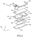
- the base 104 can include a trim or a retaining structure 500, a top cover 502, a case 504, the wireless charger 508, padding 512 and a back cover 514.
- the wireless charger 508 can be adapted to communicate with the wireless receiver 300.
- the wireless charger 508 can include a charging feature 510 that is adapted to transmit a wireless power signal that can be received by the charge receiving feature 308.
- the wireless charger 508 can include transmitting circuitry 509 operatively coupled to the charging feature 510 and to the power supply 110.
- the transmitting circuitry 509 can receive power from the power supply 110 and can convert the received power into a power signal usable by the charging feature 510.
- the charging feature 510 may then generate and/or transmit the wireless power signal to the charge receiving feature 308, from where it can be received by the receiving circuitry 309.
- the receiving circuitry 309 can convert this power signal into a power signal usable by the remote controller 202 and then transmit the usable power signal to the remote controller 202.
- the back cover 514 can include coupling features 515 that can be used to couple the back cover 514 to a portion of the aircraft 101, such as an armrest or a seat back.
- the back cover 514 can include a portion of the aircraft 101.
- an armrest or other component of the aircraft 101 can be coupled to the case 504 and protect the wireless charger 508 and, thus, be referred to as the back cover 514.
- the back cover 514 can protect the wireless charger 508 from any force being exerted on the base from the negative H direction.
- the back cover 514 can include any material.
- the back cover 514 can include a plastic, a composite material, a metal, a natural material such as leather, or the like.
- the back cover 514 can include a metal without significant detriment to performance of the SCU 100.
- the case 504 can include additional coupling features usable to connect the case 504 to the back cover 514.
- the wireless charger 508 may be positioned within a volume defined by the case 504 and the back cover 514.
- the case 504 can protect the wireless charger 508 from any force being exerted on the base 104 from the positive H direction.
- the case 504 and the back cover 514 can at least partially seal the wireless charger from external debris.
- the case 504 can include base magnets 516 including a first base magnet 516A and a second base magnet 516B.
- the remote magnets 306 of the control device 102 can be attracted to the base magnets 516 of the base 104.
- This attraction force can cause the control device 102 to resist movement relative to the base 104 in the H direction.
- the attraction force can also cause the control device 102 to be properly aligned with the base 104 such that the wireless receiver 300 can be aligned with, and receive charge from, the wireless charger 508.
- the remote magnets 306 and the base magnets 516 function to retain the control device 102 in a mated position with the base 104.
- the case 504 can define a recess 506 that is meant to align with the charging feature 510 of the wireless charger 508.
- the recess 506 can be open on the negative H side of the case 504 and can have a thickness in the H direction that is less than a thickness of other portions of the case 504 in the H direction.
- the recess 506 is meant to align with the charging feature 510 and, due to the reduced thickness, can reduce an amount of signal interference by the case 504.
- the recess 506 may also provide a volume in which the charging feature 510 can be positioned when the base 104 is assembled.
- the case 504 can include any material, such as a plastic, a composite material, a metal, a natural material such as leather, or the like. As described above, it is desirable to prevent interference of the wireless power signal by any casings. Because the case 504 will be positioned between the wireless receiver 300 and the wireless charger 508 during charging, it is desirable for the material of the case 504 to be non-metallic. Furthermore, it is desirable for a thickness of the bottom casing 200B (at least the thickness of the recess 506) to be relatively thin, such as between 0.01 inches (0.254 millimeters (mm)) and 0.2 inches (5.08 mm) as a thin material will cause less interference than a thicker material.
- a thickness of the bottom casing 200B at least the thickness of the recess 506 to be relatively thin, such as between 0.01 inches (0.254 millimeters (mm)) and 0.2 inches (5.08 mm) as a thin material will cause less interference than a thicker material.
- the optional padding 512 is positioned between the back cover 514 and the case 504.
- the padding 512 is compressed and exerts a force in the positive H direction onto the wireless charger 508.
- This force can reduce the likelihood of the wireless charger 508 moving relative to the case 504 and the back cover 514 in all directions.
- This force can also increase the likelihood that the wireless charger 508 will be positioned as close as possible to the control device 102 in the H direction in response to the control device 102 being coupled to the base 104.
- the padding 512 can be replaced by one or more springs configured to compress in the H direction in response to the case 504 being coupled to the back cover 514.
- the wireless charger 508 may be directly coupled to the case 504 such as via a fastener, glue or the like.
- the optional top cover 502 may increase the aesthetics of the base 104.
- the top cover 502 can include any material, such as a plastic, a composite material, a metal, a natural material such as leather, or the like. As described above, it is desirable to prevent interference of the wireless power signal by any casings. Because the top cover 502 will be positioned between the wireless receiver 300 and the wireless charger 508, it is desirable for the material of the top cover 502 to be non-metallic. Furthermore, it is desirable for a thickness of the top cover 502 to be relatively thin, such as between 0.01 inches (0.254 millimeters (mm)) and 0.2 inches (5.08 mm) as a thin material will cause less interference than a thicker material.
- the top cover 502 it is desirable for the top cover 502 to have a distance in the H direction that is sufficient to reduce observable wear to the top cover 502 while still reducing the amount of interference with the wireless power signal.
- the top cover 502 can include leather. Leather is visually appealing and can also provide friction with the control device 102, further resisting movement of the control device 102 relative to the base.
- the top cover 502 can be coupled to the case 504 and/or to the back cover 514 in any fashion.
- fasteners may be used to couple the top cover 502 to the case 504.
- the top cover 502 may instead snugly fit about the case 504 such that friction between the top cover 502 and the case 504 reduce the likelihood of the top cover 502 becoming removed from the case 504.
- the retaining structure 500 can include the first wall 400, the second wall 402 and the third wall 404.
- the retaining structure 500 may be coupled to any of the top cover 502, the case 504, the back cover 514 and/or directly to the surface of the aircraft 101.
- the retaining structure 500 can include any material such as a plastic, a composite material, a metal, a natural material such as leather, or the like.
- the retaining structure 500 may be composed of plastic and a chrome plating on the plastic to improve the aesthetic appeal of the base 104.
- references to "one embodiment”, “an embodiment”, “an example embodiment”, etc. indicate that the embodiment described may include a particular feature, structure, or characteristic, but every embodiment may not necessarily include the particular feature, structure, or characteristic. Moreover, such phrases are not necessarily referring to the same embodiment. Further, when a particular feature, structure, or characteristic is described in connection with an embodiment, it is submitted that it is within the knowledge of one skilled in the art to affect such feature, structure, or characteristic in connection with other embodiments whether or not explicitly described. After reading the description, it will be apparent to one skilled in the relevant art(s) how to implement the disclosure in alternative embodiments.
Landscapes
- Engineering & Computer Science (AREA)
- Power Engineering (AREA)
- Aviation & Aerospace Engineering (AREA)
- Computer Networks & Wireless Communication (AREA)
- Charge And Discharge Circuits For Batteries Or The Like (AREA)
- Selective Calling Equipment (AREA)
Claims (11)
- Drahtlose Ladestation (104) zur Verwendung in einem Luftfahrzeug, umfassend:ein drahtloses Ladegerät (508), das dazu konfiguriert ist, ein drahtloses Leistungssignal zu übertragen;eine Rückseitenabdeckung (514), die dazu konfiguriert ist, an das Luftfahrzeug gekoppelt zu sein;ein Gehäuse (504), das an die Rückseitenabdeckung gekoppelt ist, derart, dass die Rückseitenabdeckung und das Gehäuse ein Volumen definieren, in dem das drahtlose Ladegerät angeordnet ist; undeinen ersten Stationsmagneten (516A), dadurch gekennzeichnet, dass die Station (104) ferner ein Polster (512) oder eine Feder umfasst, das bzw. die zwischen dem drahtlosen Ladegerät (508) und der Rückseitenabdeckung (514) angeordnet ist und in Reaktion darauf zusammengedrückt wird, dass die Rückseitenabdeckung, die an das Gehäuse gekoppelt ist, eine Kraft auf das drahtlose Ladegerät (508) ausübt, um die Wahrscheinlichkeit zu senken, dass sich das drahtlose Ladegerät (508) im Verhältnis zum Gehäuse (504) und zur Rückseitenabdeckung (514) bewegt.
- Sitzsteuereinheit zur Verwendung in einem Luftfahrzeug, umfassend:die Station nach Anspruch 1; undeine Steuereinrichtung (102), aufweisend:eine Fernsteuerung (202), die dazu konfiguriert ist, ein System des Luftfahrzeugs drahtlose zu steuern,eine Energiespeichereinrichtung (301), die an die Fernsteuerung gekoppelt ist und dazu konfiguriert ist, elektrische Energie zu speichern,einen drahtlosen Empfänger (308), der dazu konfiguriert ist, das drahtlose Leistungssignal von dem drahtlosen Ladegerät zu empfangen und zugehörige Leistung an die Energiespeichereinrichtung zu übertragen,ein Außengehäuse (200), das wenigstens eins von der Fernsteuerung oder dem drahtlosen Empfänger wenigstens teilweise einschließt, undeinen ersten Fernmagneten (306A),wobei der erste Stationsmagnet und der erste Fernmagnet dazu konfiguriert sind, einander anzuziehen, um einer Bewegung der Steuereinrichtung im Verhältnis zur Station zu widerstehen.
- Sitzsteuereinheit nach Anspruch 2, wobei die Station ein Polster (512) beinhaltet, das zwischen dem drahtlosen Ladegerät und der Rückseitenabdeckung angeordnet ist.
- Sitzsteuereinheit nach einem der Ansprüche 2 oder 3, wobei die Station ferner eine Haltestruktur (500) beinhaltet, die dazu konfiguriert ist, einer Bewegung der Steuereinrichtung im Verhältnis zur Station zu widerstehen.
- Sitzsteuereinheit nach einem der Ansprüche 2 bis 4, wobei das drahtlose Ladegerät ferner ein Lademerkmal (510) beinhaltet, das dazu konfiguriert ist, das drahtlose Leistungssignal zu übertragen, und das Gehäuse ferner eine Vertiefung definiert, die an dem Lademerkmal ausgerichtet ist, wenn die Station montiert ist.
- Sitzsteuereinheit nach einem der Ansprüche 2 bis 5, wobei das Außengehäuse der Steuereinrichtung ein oberes Gehäuse und ein unteres Gehäuse beinhaltet, die aneinander gekoppelt sind.
- Sitzsteuereinheit nach Anspruch 6, wobei das untere Gehäuse eine Öffnung definiert, um die Wahrscheinlichkeit einer Störung des drahtlosen Leistungssignals zu senken, wenn die Steuereinrichtung an die Station wirkgekoppelt ist.
- Sitzsteuereinheit nach einem der Ansprüche 2 bis 7, wobei die Station dazu konfiguriert ist, mit der Steuereinrichtung zusammengefügt zu sein, und das drahtlose Ladegerät dazu konfiguriert ist, das drahtlose Leistungssignal in Reaktion darauf an die Steuereinrichtung zu übertragen, dass die Station mit der Steuereinrichtung zusammengefügt wird.
- Sitzsteuereinheit nach einem der Ansprüche 2 bis 8, wobei das drahtlose Leistungssignal von einer persönlichen Einrichtung empfangen werden kann, um die persönliche Einrichtung mit Leistung zu versorgen.
- Sitzsteuereinheit nach Anspruch 6, wobei das obere Gehäuse und das untere Gehäuse ein Volumen definieren, in dem die Fernsteuerung und der drahtlose Empfänger angeordnet sind.
- Sitzsteuereinheit nach Anspruch 10, wobei der erste Fernmagnet an das untere Gehäuse gekoppelt ist, wobei die Steuereinrichtung dazu konfiguriert ist, mit der Station (104) zusammengefügt zu sein, und wobei der erste Fernmagnet und der erste Stationsmagnet einander anziehen, um in Reaktion darauf, dass die Station mit der Steuereinrichtung zusammengefügt wird, die Wahrscheinlichkeit zu senken, dass sich die Steuereinrichtung von der Station löst.
Applications Claiming Priority (1)
| Application Number | Priority Date | Filing Date | Title |
|---|---|---|---|
| US14/939,869 US9876385B2 (en) | 2015-11-12 | 2015-11-12 | Seat wireless charger |
Publications (2)
| Publication Number | Publication Date |
|---|---|
| EP3168153A1 EP3168153A1 (de) | 2017-05-17 |
| EP3168153B1 true EP3168153B1 (de) | 2019-10-09 |
Family
ID=57288226
Family Applications (1)
| Application Number | Title | Priority Date | Filing Date |
|---|---|---|---|
| EP16198367.1A Active EP3168153B1 (de) | 2015-11-12 | 2016-11-11 | Drahtloses sitzladegerät |
Country Status (4)
| Country | Link |
|---|---|
| US (1) | US9876385B2 (de) |
| EP (1) | EP3168153B1 (de) |
| BR (1) | BR102016022977A2 (de) |
| CA (1) | CA2941279A1 (de) |
Families Citing this family (5)
| Publication number | Priority date | Publication date | Assignee | Title |
|---|---|---|---|---|
| CN107103698B (zh) * | 2017-06-21 | 2023-10-27 | 山东博恒新能源有限公司 | 电动汽车充电装置以及充电管理系统 |
| US11190917B2 (en) | 2017-08-28 | 2021-11-30 | Safran Seats Usa Llc | Passenger seat voice communication system |
| TW201944975A (zh) * | 2018-04-26 | 2019-12-01 | 鄭仲盛 | 智慧椅 |
| US12515799B2 (en) * | 2023-08-03 | 2026-01-06 | B/E Aerospace, Inc. | Wireless power passenger seat |
| WO2026057954A1 (en) * | 2024-09-11 | 2026-03-19 | Safran Seats GB Limited | Aircraft seat with moveable lighting device |
Family Cites Families (19)
| Publication number | Priority date | Publication date | Assignee | Title |
|---|---|---|---|---|
| US5959433A (en) | 1997-08-22 | 1999-09-28 | Centurion Intl., Inc. | Universal inductive battery charger system |
| US9425638B2 (en) | 1999-11-01 | 2016-08-23 | Anthony Sabo | Alignment independent and self-aligning inductive power transfer system |
| JP2001190029A (ja) | 1999-12-28 | 2001-07-10 | Matsushita Electric Ind Co Ltd | 充電装置 |
| US7239110B2 (en) | 2002-05-13 | 2007-07-03 | Splashpower Limited | Primary units, methods and systems for contact-less power transfer |
| KR100819753B1 (ko) | 2007-07-13 | 2008-04-08 | 주식회사 한림포스텍 | 배터리팩 솔루션을 위한 무접점충전시스템 및 그 제어방법 |
| US8203657B2 (en) * | 2008-07-11 | 2012-06-19 | Audiovox Corporation | Inductively powered mobile entertainment system |
| JP2010028969A (ja) | 2008-07-17 | 2010-02-04 | Sanyo Electric Co Ltd | 充電器 |
| US8310200B2 (en) | 2009-04-15 | 2012-11-13 | GM Global Technology Operations LLC | Inductive chargers and inductive charging systems for portable electronic devices |
| US9124308B2 (en) | 2009-05-12 | 2015-09-01 | Kimball International, Inc. | Furniture with wireless power |
| US8525471B2 (en) | 2009-12-28 | 2013-09-03 | Toyoda Gosei Co., Ltd | Moveable magnet and panel assembly useful in a vehicle |
| US8610398B2 (en) | 2011-01-04 | 2013-12-17 | Primax Electronics Ltd. | Wireless charging receiver for portable electronic device |
| US9018904B2 (en) * | 2011-08-12 | 2015-04-28 | GM Global Technology Operations LLC | Wireless battery charging apparatus mounted in a vehicle designed to reduce electromagnetic interference |
| US8826830B2 (en) | 2011-10-13 | 2014-09-09 | Nick Pajic | Tray table with rotatable inner tray for electronic device docking |
| EP2748909B1 (de) | 2011-11-30 | 2019-08-07 | Koninklijke Philips N.V. | Energieübertragungsvorrichtung zur induktiven übertragung elektrischer energie an ein tragbares elektrisches gerät |
| US9584846B2 (en) | 2011-12-16 | 2017-02-28 | Thales Avionics, Inc. | In-flight entertainment system with wireless handheld controller and cradle having controlled locking and status reporting to crew |
| US9793739B2 (en) | 2013-08-07 | 2017-10-17 | Sandisk Technologies Llc | Wireless power transmitting device |
| EP2866476B1 (de) | 2013-10-28 | 2021-05-12 | Airbus Operations GmbH | Verfahren und Flugzeugserversystem zur Kommunikation mit einer persönlichen elektronischen Vorrichtung in einem Flugzeug |
| KR20150067673A (ko) | 2013-12-10 | 2015-06-18 | 엘지전자 주식회사 | 무선 충전 장치 |
| US9401621B2 (en) * | 2014-03-14 | 2016-07-26 | Lenovo (Singapore) Pte. Ltd. | Wireless charging dock with auto-positioning |
-
2015
- 2015-11-12 US US14/939,869 patent/US9876385B2/en active Active
-
2016
- 2016-09-06 CA CA2941279A patent/CA2941279A1/en not_active Abandoned
- 2016-10-03 BR BR102016022977A patent/BR102016022977A2/pt not_active IP Right Cessation
- 2016-11-11 EP EP16198367.1A patent/EP3168153B1/de active Active
Non-Patent Citations (1)
| Title |
|---|
| None * |
Also Published As
| Publication number | Publication date |
|---|---|
| US20170141600A1 (en) | 2017-05-18 |
| US9876385B2 (en) | 2018-01-23 |
| BR102016022977A2 (pt) | 2017-05-23 |
| EP3168153A1 (de) | 2017-05-17 |
| CA2941279A1 (en) | 2017-05-12 |
Similar Documents
| Publication | Publication Date | Title |
|---|---|---|
| EP3168153A1 (de) | Drahtloses sitzladegerät | |
| JP6655550B2 (ja) | 航空機座席における誘導電力伝送 | |
| US10043612B2 (en) | Methods for forming shield materials onto inductive coils | |
| US11342777B2 (en) | Powering and/or charging with more than one protocol | |
| US9912174B2 (en) | Inductively coupled wireless power and data for a garment via a dongle | |
| US20250096607A1 (en) | System and method for infrastructure, vehicle and internet of things wireless chargers | |
| EP3328230B1 (de) | Einteiliges gehäuse mit einer batterie und einem scharnier | |
| CN206602411U (zh) | 无线充电装置 | |
| US9667092B2 (en) | Power charging kit with wireless and direct charging connectivity | |
| US12206257B2 (en) | Surface mountable wireless power transmitter for transmission at extended range | |
| US10797508B2 (en) | Portable device docking station charge mechanism | |
| US9660488B2 (en) | Electric ring with external power source | |
| US20180366971A1 (en) | Portable power charger kit for wirelessly recharging electronic devices | |
| US20150015180A1 (en) | Portable Power Charger with Wireless and Direct Charging Connectivity | |
| US20150349571A1 (en) | Electromagnetic alignment of inductive coils | |
| US20130154555A1 (en) | Sliding wireless charging tray for inductive charging of electronic devices | |
| US11600998B2 (en) | Electronic device charger | |
| US20160116183A1 (en) | Magnetically mounted wall thermostat | |
| US20160204644A1 (en) | Wireless battery charger | |
| US20160152340A1 (en) | Fixture for electronic devices, vehicle seat with integrated fixture and method for mounting an electronic device in a fixture | |
| US20190267824A1 (en) | Decorative and wearable power charger with flashlight feature and wireless charging capabilities | |
| CN202050273U (zh) | 无线充电的发射器和接收器以及手机套 | |
| CN108352713B (zh) | 铰链安装式无线充电系统和方法 | |
| KR20150084341A (ko) | 휴대용단말기의 무선 충전장치를 구비한 비행기의 승객 좌석의 음식용 트레이 및 암 레스트 | |
| EP3742579A1 (de) | Zwei-stufige drahtlose energieübertragungssystem |
Legal Events
| Date | Code | Title | Description |
|---|---|---|---|
| PUAI | Public reference made under article 153(3) epc to a published international application that has entered the european phase |
Free format text: ORIGINAL CODE: 0009012 |
|
| STAA | Information on the status of an ep patent application or granted ep patent |
Free format text: STATUS: THE APPLICATION HAS BEEN PUBLISHED |
|
| AK | Designated contracting states |
Kind code of ref document: A1 Designated state(s): AL AT BE BG CH CY CZ DE DK EE ES FI FR GB GR HR HU IE IS IT LI LT LU LV MC MK MT NL NO PL PT RO RS SE SI SK SM TR |
|
| AX | Request for extension of the european patent |
Extension state: BA ME |
|
| STAA | Information on the status of an ep patent application or granted ep patent |
Free format text: STATUS: REQUEST FOR EXAMINATION WAS MADE |
|
| 17P | Request for examination filed |
Effective date: 20171116 |
|
| RBV | Designated contracting states (corrected) |
Designated state(s): AL AT BE BG CH CY CZ DE DK EE ES FI FR GB GR HR HU IE IS IT LI LT LU LV MC MK MT NL NO PL PT RO RS SE SI SK SM TR |
|
| STAA | Information on the status of an ep patent application or granted ep patent |
Free format text: STATUS: EXAMINATION IS IN PROGRESS |
|
| 17Q | First examination report despatched |
Effective date: 20180316 |
|
| GRAP | Despatch of communication of intention to grant a patent |
Free format text: ORIGINAL CODE: EPIDOSNIGR1 |
|
| STAA | Information on the status of an ep patent application or granted ep patent |
Free format text: STATUS: GRANT OF PATENT IS INTENDED |
|
| INTG | Intention to grant announced |
Effective date: 20190418 |
|
| GRAS | Grant fee paid |
Free format text: ORIGINAL CODE: EPIDOSNIGR3 |
|
| GRAA | (expected) grant |
Free format text: ORIGINAL CODE: 0009210 |
|
| STAA | Information on the status of an ep patent application or granted ep patent |
Free format text: STATUS: THE PATENT HAS BEEN GRANTED |
|
| AK | Designated contracting states |
Kind code of ref document: B1 Designated state(s): AL AT BE BG CH CY CZ DE DK EE ES FI FR GB GR HR HU IE IS IT LI LT LU LV MC MK MT NL NO PL PT RO RS SE SI SK SM TR |
|
| REG | Reference to a national code |
Ref country code: GB Ref legal event code: FG4D |
|
| REG | Reference to a national code |
Ref country code: CH Ref legal event code: EP |
|
| REG | Reference to a national code |
Ref country code: IE Ref legal event code: FG4D |
|
| REG | Reference to a national code |
Ref country code: DE Ref legal event code: R096 Ref document number: 602016022025 Country of ref document: DE |
|
| REG | Reference to a national code |
Ref country code: AT Ref legal event code: REF Ref document number: 1188509 Country of ref document: AT Kind code of ref document: T Effective date: 20191115 |
|
| REG | Reference to a national code |
Ref country code: NL Ref legal event code: MP Effective date: 20191009 |
|
| REG | Reference to a national code |
Ref country code: LT Ref legal event code: MG4D |
|
| REG | Reference to a national code |
Ref country code: AT Ref legal event code: MK05 Ref document number: 1188509 Country of ref document: AT Kind code of ref document: T Effective date: 20191009 |
|
| PG25 | Lapsed in a contracting state [announced via postgrant information from national office to epo] |
Ref country code: PT Free format text: LAPSE BECAUSE OF FAILURE TO SUBMIT A TRANSLATION OF THE DESCRIPTION OR TO PAY THE FEE WITHIN THE PRESCRIBED TIME-LIMIT Effective date: 20200210 Ref country code: AT Free format text: LAPSE BECAUSE OF FAILURE TO SUBMIT A TRANSLATION OF THE DESCRIPTION OR TO PAY THE FEE WITHIN THE PRESCRIBED TIME-LIMIT Effective date: 20191009 Ref country code: ES Free format text: LAPSE BECAUSE OF FAILURE TO SUBMIT A TRANSLATION OF THE DESCRIPTION OR TO PAY THE FEE WITHIN THE PRESCRIBED TIME-LIMIT Effective date: 20191009 Ref country code: PL Free format text: LAPSE BECAUSE OF FAILURE TO SUBMIT A TRANSLATION OF THE DESCRIPTION OR TO PAY THE FEE WITHIN THE PRESCRIBED TIME-LIMIT Effective date: 20191009 Ref country code: NO Free format text: LAPSE BECAUSE OF FAILURE TO SUBMIT A TRANSLATION OF THE DESCRIPTION OR TO PAY THE FEE WITHIN THE PRESCRIBED TIME-LIMIT Effective date: 20200109 Ref country code: SE Free format text: LAPSE BECAUSE OF FAILURE TO SUBMIT A TRANSLATION OF THE DESCRIPTION OR TO PAY THE FEE WITHIN THE PRESCRIBED TIME-LIMIT Effective date: 20191009 Ref country code: LV Free format text: LAPSE BECAUSE OF FAILURE TO SUBMIT A TRANSLATION OF THE DESCRIPTION OR TO PAY THE FEE WITHIN THE PRESCRIBED TIME-LIMIT Effective date: 20191009 Ref country code: FI Free format text: LAPSE BECAUSE OF FAILURE TO SUBMIT A TRANSLATION OF THE DESCRIPTION OR TO PAY THE FEE WITHIN THE PRESCRIBED TIME-LIMIT Effective date: 20191009 Ref country code: BG Free format text: LAPSE BECAUSE OF FAILURE TO SUBMIT A TRANSLATION OF THE DESCRIPTION OR TO PAY THE FEE WITHIN THE PRESCRIBED TIME-LIMIT Effective date: 20200109 Ref country code: GR Free format text: LAPSE BECAUSE OF FAILURE TO SUBMIT A TRANSLATION OF THE DESCRIPTION OR TO PAY THE FEE WITHIN THE PRESCRIBED TIME-LIMIT Effective date: 20200110 Ref country code: LT Free format text: LAPSE BECAUSE OF FAILURE TO SUBMIT A TRANSLATION OF THE DESCRIPTION OR TO PAY THE FEE WITHIN THE PRESCRIBED TIME-LIMIT Effective date: 20191009 Ref country code: NL Free format text: LAPSE BECAUSE OF FAILURE TO SUBMIT A TRANSLATION OF THE DESCRIPTION OR TO PAY THE FEE WITHIN THE PRESCRIBED TIME-LIMIT Effective date: 20191009 |
|
| PG25 | Lapsed in a contracting state [announced via postgrant information from national office to epo] |
Ref country code: RS Free format text: LAPSE BECAUSE OF FAILURE TO SUBMIT A TRANSLATION OF THE DESCRIPTION OR TO PAY THE FEE WITHIN THE PRESCRIBED TIME-LIMIT Effective date: 20191009 Ref country code: HR Free format text: LAPSE BECAUSE OF FAILURE TO SUBMIT A TRANSLATION OF THE DESCRIPTION OR TO PAY THE FEE WITHIN THE PRESCRIBED TIME-LIMIT Effective date: 20191009 Ref country code: IS Free format text: LAPSE BECAUSE OF FAILURE TO SUBMIT A TRANSLATION OF THE DESCRIPTION OR TO PAY THE FEE WITHIN THE PRESCRIBED TIME-LIMIT Effective date: 20200224 |
|
| PG25 | Lapsed in a contracting state [announced via postgrant information from national office to epo] |
Ref country code: AL Free format text: LAPSE BECAUSE OF FAILURE TO SUBMIT A TRANSLATION OF THE DESCRIPTION OR TO PAY THE FEE WITHIN THE PRESCRIBED TIME-LIMIT Effective date: 20191009 |
|
| REG | Reference to a national code |
Ref country code: CH Ref legal event code: PL |
|
| REG | Reference to a national code |
Ref country code: DE Ref legal event code: R097 Ref document number: 602016022025 Country of ref document: DE |
|
| PG2D | Information on lapse in contracting state deleted |
Ref country code: IS |
|
| PG25 | Lapsed in a contracting state [announced via postgrant information from national office to epo] |
Ref country code: RO Free format text: LAPSE BECAUSE OF FAILURE TO SUBMIT A TRANSLATION OF THE DESCRIPTION OR TO PAY THE FEE WITHIN THE PRESCRIBED TIME-LIMIT Effective date: 20191009 Ref country code: CZ Free format text: LAPSE BECAUSE OF FAILURE TO SUBMIT A TRANSLATION OF THE DESCRIPTION OR TO PAY THE FEE WITHIN THE PRESCRIBED TIME-LIMIT Effective date: 20191009 Ref country code: LU Free format text: LAPSE BECAUSE OF NON-PAYMENT OF DUE FEES Effective date: 20191111 Ref country code: EE Free format text: LAPSE BECAUSE OF FAILURE TO SUBMIT A TRANSLATION OF THE DESCRIPTION OR TO PAY THE FEE WITHIN THE PRESCRIBED TIME-LIMIT Effective date: 20191009 Ref country code: DK Free format text: LAPSE BECAUSE OF FAILURE TO SUBMIT A TRANSLATION OF THE DESCRIPTION OR TO PAY THE FEE WITHIN THE PRESCRIBED TIME-LIMIT Effective date: 20191009 Ref country code: LI Free format text: LAPSE BECAUSE OF NON-PAYMENT OF DUE FEES Effective date: 20191130 Ref country code: MC Free format text: LAPSE BECAUSE OF FAILURE TO SUBMIT A TRANSLATION OF THE DESCRIPTION OR TO PAY THE FEE WITHIN THE PRESCRIBED TIME-LIMIT Effective date: 20191009 Ref country code: CH Free format text: LAPSE BECAUSE OF NON-PAYMENT OF DUE FEES Effective date: 20191130 Ref country code: IS Free format text: LAPSE BECAUSE OF FAILURE TO SUBMIT A TRANSLATION OF THE DESCRIPTION OR TO PAY THE FEE WITHIN THE PRESCRIBED TIME-LIMIT Effective date: 20200209 |
|
| PLBE | No opposition filed within time limit |
Free format text: ORIGINAL CODE: 0009261 |
|
| STAA | Information on the status of an ep patent application or granted ep patent |
Free format text: STATUS: NO OPPOSITION FILED WITHIN TIME LIMIT |
|
| REG | Reference to a national code |
Ref country code: BE Ref legal event code: MM Effective date: 20191130 |
|
| PG25 | Lapsed in a contracting state [announced via postgrant information from national office to epo] |
Ref country code: SK Free format text: LAPSE BECAUSE OF FAILURE TO SUBMIT A TRANSLATION OF THE DESCRIPTION OR TO PAY THE FEE WITHIN THE PRESCRIBED TIME-LIMIT Effective date: 20191009 Ref country code: IT Free format text: LAPSE BECAUSE OF FAILURE TO SUBMIT A TRANSLATION OF THE DESCRIPTION OR TO PAY THE FEE WITHIN THE PRESCRIBED TIME-LIMIT Effective date: 20191009 Ref country code: SM Free format text: LAPSE BECAUSE OF FAILURE TO SUBMIT A TRANSLATION OF THE DESCRIPTION OR TO PAY THE FEE WITHIN THE PRESCRIBED TIME-LIMIT Effective date: 20191009 |
|
| 26N | No opposition filed |
Effective date: 20200710 |
|
| PG25 | Lapsed in a contracting state [announced via postgrant information from national office to epo] |
Ref country code: IE Free format text: LAPSE BECAUSE OF NON-PAYMENT OF DUE FEES Effective date: 20191111 |
|
| PG25 | Lapsed in a contracting state [announced via postgrant information from national office to epo] |
Ref country code: BE Free format text: LAPSE BECAUSE OF NON-PAYMENT OF DUE FEES Effective date: 20191130 Ref country code: SI Free format text: LAPSE BECAUSE OF FAILURE TO SUBMIT A TRANSLATION OF THE DESCRIPTION OR TO PAY THE FEE WITHIN THE PRESCRIBED TIME-LIMIT Effective date: 20191009 |
|
| PG25 | Lapsed in a contracting state [announced via postgrant information from national office to epo] |
Ref country code: CY Free format text: LAPSE BECAUSE OF FAILURE TO SUBMIT A TRANSLATION OF THE DESCRIPTION OR TO PAY THE FEE WITHIN THE PRESCRIBED TIME-LIMIT Effective date: 20191009 |
|
| PG25 | Lapsed in a contracting state [announced via postgrant information from national office to epo] |
Ref country code: HU Free format text: LAPSE BECAUSE OF FAILURE TO SUBMIT A TRANSLATION OF THE DESCRIPTION OR TO PAY THE FEE WITHIN THE PRESCRIBED TIME-LIMIT; INVALID AB INITIO Effective date: 20161111 Ref country code: MT Free format text: LAPSE BECAUSE OF FAILURE TO SUBMIT A TRANSLATION OF THE DESCRIPTION OR TO PAY THE FEE WITHIN THE PRESCRIBED TIME-LIMIT Effective date: 20191009 |
|
| PG25 | Lapsed in a contracting state [announced via postgrant information from national office to epo] |
Ref country code: TR Free format text: LAPSE BECAUSE OF FAILURE TO SUBMIT A TRANSLATION OF THE DESCRIPTION OR TO PAY THE FEE WITHIN THE PRESCRIBED TIME-LIMIT Effective date: 20191009 |
|
| PG25 | Lapsed in a contracting state [announced via postgrant information from national office to epo] |
Ref country code: MK Free format text: LAPSE BECAUSE OF FAILURE TO SUBMIT A TRANSLATION OF THE DESCRIPTION OR TO PAY THE FEE WITHIN THE PRESCRIBED TIME-LIMIT Effective date: 20191009 |
|
| P01 | Opt-out of the competence of the unified patent court (upc) registered |
Effective date: 20230521 |
|
| PGFP | Annual fee paid to national office [announced via postgrant information from national office to epo] |
Ref country code: DE Payment date: 20251022 Year of fee payment: 10 |
|
| PGFP | Annual fee paid to national office [announced via postgrant information from national office to epo] |
Ref country code: GB Payment date: 20251023 Year of fee payment: 10 |
|
| PGFP | Annual fee paid to national office [announced via postgrant information from national office to epo] |
Ref country code: FR Payment date: 20251022 Year of fee payment: 10 |