EP3166524B1 - Cathéter d'ablation par radiofréquence d'artère pulmonaire synchrone multi-pôles - Google Patents
Cathéter d'ablation par radiofréquence d'artère pulmonaire synchrone multi-pôles Download PDFInfo
- Publication number
- EP3166524B1 EP3166524B1 EP15818364.0A EP15818364A EP3166524B1 EP 3166524 B1 EP3166524 B1 EP 3166524B1 EP 15818364 A EP15818364 A EP 15818364A EP 3166524 B1 EP3166524 B1 EP 3166524B1
- Authority
- EP
- European Patent Office
- Prior art keywords
- annular ring
- pulmonary artery
- ablation
- catheter
- electrode
- Prior art date
- Legal status (The legal status is an assumption and is not a legal conclusion. Google has not performed a legal analysis and makes no representation as to the accuracy of the status listed.)
- Active
Links
- 210000001147 pulmonary artery Anatomy 0.000 title claims description 184
- 238000007674 radiofrequency ablation Methods 0.000 title description 10
- 230000005405 multipole Effects 0.000 title description 9
- 230000001360 synchronised effect Effects 0.000 title description 9
- 238000002679 ablation Methods 0.000 description 152
- 238000000034 method Methods 0.000 description 98
- 238000011282 treatment Methods 0.000 description 42
- 229940079593 drug Drugs 0.000 description 31
- 239000003814 drug Substances 0.000 description 31
- 208000002815 pulmonary hypertension Diseases 0.000 description 26
- 230000002889 sympathetic effect Effects 0.000 description 25
- 238000010586 diagram Methods 0.000 description 23
- 230000002685 pulmonary effect Effects 0.000 description 23
- 210000005036 nerve Anatomy 0.000 description 22
- 238000005259 measurement Methods 0.000 description 21
- 239000007787 solid Substances 0.000 description 16
- 230000002638 denervation Effects 0.000 description 15
- 210000004126 nerve fiber Anatomy 0.000 description 14
- 241001465754 Metazoa Species 0.000 description 12
- 230000006872 improvement Effects 0.000 description 12
- 206010064911 Pulmonary arterial hypertension Diseases 0.000 description 11
- 230000000875 corresponding effect Effects 0.000 description 11
- WABPQHHGFIMREM-UHFFFAOYSA-N lead(0) Chemical compound [Pb] WABPQHHGFIMREM-UHFFFAOYSA-N 0.000 description 11
- 230000036593 pulmonary vascular resistance Effects 0.000 description 11
- 208000004248 Familial Primary Pulmonary Hypertension Diseases 0.000 description 10
- 230000000004 hemodynamic effect Effects 0.000 description 10
- 230000009467 reduction Effects 0.000 description 10
- 210000001367 artery Anatomy 0.000 description 9
- 210000004072 lung Anatomy 0.000 description 9
- 208000020875 Idiopathic pulmonary arterial hypertension Diseases 0.000 description 8
- 210000003050 axon Anatomy 0.000 description 8
- 230000008859 change Effects 0.000 description 8
- 230000002474 noradrenergic effect Effects 0.000 description 8
- 101800000407 Brain natriuretic peptide 32 Proteins 0.000 description 7
- 102400000667 Brain natriuretic peptide 32 Human genes 0.000 description 7
- 101800002247 Brain natriuretic peptide 45 Proteins 0.000 description 7
- 230000001746 atrial effect Effects 0.000 description 7
- 230000030214 innervation Effects 0.000 description 7
- 230000003730 sympathetic denervation Effects 0.000 description 7
- 241000282472 Canis lupus familiaris Species 0.000 description 6
- 210000003484 anatomy Anatomy 0.000 description 6
- 230000004872 arterial blood pressure Effects 0.000 description 6
- 239000008280 blood Substances 0.000 description 6
- 210000004369 blood Anatomy 0.000 description 6
- 230000007423 decrease Effects 0.000 description 6
- 208000037265 diseases, disorders, signs and symptoms Diseases 0.000 description 6
- 239000010935 stainless steel Substances 0.000 description 6
- 241000282465 Canis Species 0.000 description 5
- 241000282414 Homo sapiens Species 0.000 description 5
- FAPWRFPIFSIZLT-UHFFFAOYSA-M Sodium chloride Chemical compound [Na+].[Cl-] FAPWRFPIFSIZLT-UHFFFAOYSA-M 0.000 description 5
- 238000004458 analytical method Methods 0.000 description 5
- QVGXLLKOCUKJST-UHFFFAOYSA-N atomic oxygen Chemical compound [O] QVGXLLKOCUKJST-UHFFFAOYSA-N 0.000 description 5
- 230000017531 blood circulation Effects 0.000 description 5
- 230000000747 cardiac effect Effects 0.000 description 5
- 230000001684 chronic effect Effects 0.000 description 5
- 230000034994 death Effects 0.000 description 5
- 231100000517 death Toxicity 0.000 description 5
- 230000003205 diastolic effect Effects 0.000 description 5
- LOKCTEFSRHRXRJ-UHFFFAOYSA-I dipotassium trisodium dihydrogen phosphate hydrogen phosphate dichloride Chemical compound P(=O)(O)(O)[O-].[K+].P(=O)(O)([O-])[O-].[Na+].[Na+].[Cl-].[K+].[Cl-].[Na+] LOKCTEFSRHRXRJ-UHFFFAOYSA-I 0.000 description 5
- 201000010099 disease Diseases 0.000 description 5
- 238000002592 echocardiography Methods 0.000 description 5
- 229910052760 oxygen Inorganic materials 0.000 description 5
- 239000001301 oxygen Substances 0.000 description 5
- 239000002953 phosphate buffered saline Substances 0.000 description 5
- 239000011780 sodium chloride Substances 0.000 description 5
- 238000002604 ultrasonography Methods 0.000 description 5
- 239000004642 Polyimide Substances 0.000 description 4
- 210000002808 connective tissue Anatomy 0.000 description 4
- 239000000835 fiber Substances 0.000 description 4
- 238000001802 infusion Methods 0.000 description 4
- 239000000463 material Substances 0.000 description 4
- 230000004007 neuromodulation Effects 0.000 description 4
- 229910001000 nickel titanium Inorganic materials 0.000 description 4
- 229920001721 polyimide Polymers 0.000 description 4
- 230000006425 pulmonary artery denervation Effects 0.000 description 4
- 241000894007 species Species 0.000 description 4
- 208000024891 symptom Diseases 0.000 description 4
- 230000002861 ventricular Effects 0.000 description 4
- PJVWKTKQMONHTI-UHFFFAOYSA-N warfarin Chemical compound OC=1C2=CC=CC=C2OC(=O)C=1C(CC(=O)C)C1=CC=CC=C1 PJVWKTKQMONHTI-UHFFFAOYSA-N 0.000 description 4
- 229960005080 warfarin Drugs 0.000 description 4
- SFLSHLFXELFNJZ-QMMMGPOBSA-N (-)-norepinephrine Chemical compound NC[C@H](O)C1=CC=C(O)C(O)=C1 SFLSHLFXELFNJZ-QMMMGPOBSA-N 0.000 description 3
- 241000700199 Cavia porcellus Species 0.000 description 3
- 206010008479 Chest Pain Diseases 0.000 description 3
- LTMHDMANZUZIPE-AMTYYWEZSA-N Digoxin Natural products O([C@H]1[C@H](C)O[C@H](O[C@@H]2C[C@@H]3[C@@](C)([C@@H]4[C@H]([C@]5(O)[C@](C)([C@H](O)C4)[C@H](C4=CC(=O)OC4)CC5)CC3)CC2)C[C@@H]1O)[C@H]1O[C@H](C)[C@@H](O[C@H]2O[C@@H](C)[C@H](O)[C@@H](O)C2)[C@@H](O)C1 LTMHDMANZUZIPE-AMTYYWEZSA-N 0.000 description 3
- 241000282412 Homo Species 0.000 description 3
- 208000005228 Pericardial Effusion Diseases 0.000 description 3
- 238000003848 UV Light-Curing Methods 0.000 description 3
- 239000000853 adhesive Substances 0.000 description 3
- 230000001070 adhesive effect Effects 0.000 description 3
- 238000002583 angiography Methods 0.000 description 3
- 230000000903 blocking effect Effects 0.000 description 3
- 210000000038 chest Anatomy 0.000 description 3
- 238000012790 confirmation Methods 0.000 description 3
- 208000018631 connective tissue disease Diseases 0.000 description 3
- 230000002596 correlated effect Effects 0.000 description 3
- 230000003247 decreasing effect Effects 0.000 description 3
- 238000013461 design Methods 0.000 description 3
- LTMHDMANZUZIPE-PUGKRICDSA-N digoxin Chemical compound C1[C@H](O)[C@H](O)[C@@H](C)O[C@H]1O[C@@H]1[C@@H](C)O[C@@H](O[C@@H]2[C@H](O[C@@H](O[C@@H]3C[C@@H]4[C@]([C@@H]5[C@H]([C@]6(CC[C@@H]([C@@]6(C)[C@H](O)C5)C=5COC(=O)C=5)O)CC4)(C)CC3)C[C@@H]2O)C)C[C@@H]1O LTMHDMANZUZIPE-PUGKRICDSA-N 0.000 description 3
- 229960005156 digoxin Drugs 0.000 description 3
- LTMHDMANZUZIPE-UHFFFAOYSA-N digoxine Natural products C1C(O)C(O)C(C)OC1OC1C(C)OC(OC2C(OC(OC3CC4C(C5C(C6(CCC(C6(C)C(O)C5)C=5COC(=O)C=5)O)CC4)(C)CC3)CC2O)C)CC1O LTMHDMANZUZIPE-UHFFFAOYSA-N 0.000 description 3
- 239000002934 diuretic Substances 0.000 description 3
- 230000000694 effects Effects 0.000 description 3
- 206010016256 fatigue Diseases 0.000 description 3
- 238000000386 microscopy Methods 0.000 description 3
- 230000001537 neural effect Effects 0.000 description 3
- 229960002748 norepinephrine Drugs 0.000 description 3
- SFLSHLFXELFNJZ-UHFFFAOYSA-N norepinephrine Natural products NCC(O)C1=CC=C(O)C(O)=C1 SFLSHLFXELFNJZ-UHFFFAOYSA-N 0.000 description 3
- 210000004912 pericardial fluid Anatomy 0.000 description 3
- 239000002861 polymer material Substances 0.000 description 3
- 210000003492 pulmonary vein Anatomy 0.000 description 3
- 230000000284 resting effect Effects 0.000 description 3
- 239000000243 solution Substances 0.000 description 3
- 229910001220 stainless steel Inorganic materials 0.000 description 3
- 229910001256 stainless steel alloy Inorganic materials 0.000 description 3
- 230000000638 stimulation Effects 0.000 description 3
- 238000012360 testing method Methods 0.000 description 3
- 210000001519 tissue Anatomy 0.000 description 3
- 230000002792 vascular Effects 0.000 description 3
- 210000001631 vena cava inferior Anatomy 0.000 description 3
- 238000003466 welding Methods 0.000 description 3
- 206010002329 Aneurysm Diseases 0.000 description 2
- 206010003658 Atrial Fibrillation Diseases 0.000 description 2
- 229910001020 Au alloy Inorganic materials 0.000 description 2
- 208000026151 Chronic thromboembolic pulmonary hypertension Diseases 0.000 description 2
- 208000002330 Congenital Heart Defects Diseases 0.000 description 2
- 108010065372 Dynorphins Proteins 0.000 description 2
- 208000000059 Dyspnea Diseases 0.000 description 2
- 206010013975 Dyspnoeas Diseases 0.000 description 2
- 208000005189 Embolism Diseases 0.000 description 2
- PXGOKWXKJXAPGV-UHFFFAOYSA-N Fluorine Chemical compound FF PXGOKWXKJXAPGV-UHFFFAOYSA-N 0.000 description 2
- 206010018852 Haematoma Diseases 0.000 description 2
- 206010020772 Hypertension Diseases 0.000 description 2
- 101800001904 NT-proBNP Proteins 0.000 description 2
- 102400001263 NT-proBNP Human genes 0.000 description 2
- 229910000990 Ni alloy Inorganic materials 0.000 description 2
- 229910000566 Platinum-iridium alloy Inorganic materials 0.000 description 2
- 239000004962 Polyamide-imide Substances 0.000 description 2
- 102100024622 Proenkephalin-B Human genes 0.000 description 2
- 208000007536 Thrombosis Diseases 0.000 description 2
- RTAQQCXQSZGOHL-UHFFFAOYSA-N Titanium Chemical compound [Ti] RTAQQCXQSZGOHL-UHFFFAOYSA-N 0.000 description 2
- 201000001943 Tricuspid Valve Insufficiency Diseases 0.000 description 2
- 206010044640 Tricuspid valve incompetence Diseases 0.000 description 2
- 108010003205 Vasoactive Intestinal Peptide Proteins 0.000 description 2
- 102400000015 Vasoactive intestinal peptide Human genes 0.000 description 2
- 230000004913 activation Effects 0.000 description 2
- OIRDTQYFTABQOQ-KQYNXXCUSA-N adenosine Chemical compound C1=NC=2C(N)=NC=NC=2N1[C@@H]1O[C@H](CO)[C@@H](O)[C@H]1O OIRDTQYFTABQOQ-KQYNXXCUSA-N 0.000 description 2
- 210000002565 arteriole Anatomy 0.000 description 2
- 230000008901 benefit Effects 0.000 description 2
- GJPICJJJRGTNOD-UHFFFAOYSA-N bosentan Chemical compound COC1=CC=CC=C1OC(C(=NC(=N1)C=2N=CC=CN=2)OCCO)=C1NS(=O)(=O)C1=CC=C(C(C)(C)C)C=C1 GJPICJJJRGTNOD-UHFFFAOYSA-N 0.000 description 2
- 229960003065 bosentan Drugs 0.000 description 2
- 238000002725 brachytherapy Methods 0.000 description 2
- 239000013043 chemical agent Substances 0.000 description 2
- 239000003795 chemical substances by application Substances 0.000 description 2
- 239000004020 conductor Substances 0.000 description 2
- 208000028831 congenital heart disease Diseases 0.000 description 2
- 230000001276 controlling effect Effects 0.000 description 2
- 230000006378 damage Effects 0.000 description 2
- 238000003745 diagnosis Methods 0.000 description 2
- 238000009826 distribution Methods 0.000 description 2
- 230000001882 diuretic effect Effects 0.000 description 2
- 238000004520 electroporation Methods 0.000 description 2
- 210000003191 femoral vein Anatomy 0.000 description 2
- 229910052731 fluorine Inorganic materials 0.000 description 2
- 239000011737 fluorine Substances 0.000 description 2
- 230000006870 function Effects 0.000 description 2
- 239000003292 glue Substances 0.000 description 2
- PCHJSUWPFVWCPO-UHFFFAOYSA-N gold Chemical compound [Au] PCHJSUWPFVWCPO-UHFFFAOYSA-N 0.000 description 2
- 239000010931 gold Substances 0.000 description 2
- 208000019622 heart disease Diseases 0.000 description 2
- 230000004217 heart function Effects 0.000 description 2
- 230000000977 initiatory effect Effects 0.000 description 2
- 238000007689 inspection Methods 0.000 description 2
- VBUWHHLIZKOSMS-RIWXPGAOSA-N invicorp Chemical compound C([C@@H](C(=O)N[C@@H](CC(C)C)C(=O)N[C@@H](CC(N)=O)C(=O)N[C@@H](CO)C(=O)N[C@@H]([C@@H](C)CC)C(=O)N[C@@H](CC(C)C)C(=O)N[C@@H](CC(N)=O)C(O)=O)NC(=O)[C@H](CCCCN)NC(=O)[C@H](CCCCN)NC(=O)[C@@H](NC(=O)[C@H](C)NC(=O)[C@H](CCSC)NC(=O)[C@H](CCC(N)=O)NC(=O)[C@H](CCCCN)NC(=O)[C@H](CCCNC(N)=N)NC(=O)[C@H](CC(C)C)NC(=O)[C@H](CCCNC(N)=N)NC(=O)[C@@H](NC(=O)[C@H](CC=1C=CC(O)=CC=1)NC(=O)[C@H](CC(N)=O)NC(=O)[C@H](CC(O)=O)NC(=O)[C@@H](NC(=O)[C@H](CC=1C=CC=CC=1)NC(=O)[C@@H](NC(=O)[C@H](C)NC(=O)[C@H](CC(O)=O)NC(=O)[C@H](CO)NC(=O)[C@@H](N)CC=1NC=NC=1)C(C)C)[C@@H](C)O)[C@@H](C)O)C(C)C)C1=CC=C(O)C=C1 VBUWHHLIZKOSMS-RIWXPGAOSA-N 0.000 description 2
- 210000004731 jugular vein Anatomy 0.000 description 2
- 238000002372 labelling Methods 0.000 description 2
- 239000007788 liquid Substances 0.000 description 2
- 230000001404 mediated effect Effects 0.000 description 2
- 238000012544 monitoring process Methods 0.000 description 2
- 230000007383 nerve stimulation Effects 0.000 description 2
- 210000002569 neuron Anatomy 0.000 description 2
- 210000000056 organ Anatomy 0.000 description 2
- 230000001734 parasympathetic effect Effects 0.000 description 2
- 230000036961 partial effect Effects 0.000 description 2
- 230000008506 pathogenesis Effects 0.000 description 2
- HWLDNSXPUQTBOD-UHFFFAOYSA-N platinum-iridium alloy Chemical class [Ir].[Pt] HWLDNSXPUQTBOD-UHFFFAOYSA-N 0.000 description 2
- 229920002312 polyamide-imide Polymers 0.000 description 2
- 229920000728 polyester Polymers 0.000 description 2
- 229920002635 polyurethane Polymers 0.000 description 2
- 239000004814 polyurethane Substances 0.000 description 2
- 201000010298 pulmonary valve insufficiency Diseases 0.000 description 2
- 208000009138 pulmonary valve stenosis Diseases 0.000 description 2
- 208000030390 pulmonic stenosis Diseases 0.000 description 2
- 238000011160 research Methods 0.000 description 2
- 230000011218 segmentation Effects 0.000 description 2
- 229910001285 shape-memory alloy Inorganic materials 0.000 description 2
- BNRNXUUZRGQAQC-UHFFFAOYSA-N sildenafil Chemical compound CCCC1=NN(C)C(C(N2)=O)=C1N=C2C(C(=CC=1)OCC)=CC=1S(=O)(=O)N1CCN(C)CC1 BNRNXUUZRGQAQC-UHFFFAOYSA-N 0.000 description 2
- 230000002459 sustained effect Effects 0.000 description 2
- 230000035488 systolic blood pressure Effects 0.000 description 2
- 238000002560 therapeutic procedure Methods 0.000 description 2
- 230000001732 thrombotic effect Effects 0.000 description 2
- 239000010936 titanium Substances 0.000 description 2
- 229910052719 titanium Inorganic materials 0.000 description 2
- 238000002054 transplantation Methods 0.000 description 2
- 210000005166 vasculature Anatomy 0.000 description 2
- BSYNRYMUTXBXSQ-UHFFFAOYSA-N Aspirin Chemical compound CC(=O)OC1=CC=CC=C1C(O)=O BSYNRYMUTXBXSQ-UHFFFAOYSA-N 0.000 description 1
- 239000005552 B01AC04 - Clopidogrel Substances 0.000 description 1
- 239000002126 C01EB10 - Adenosine Substances 0.000 description 1
- 229940127291 Calcium channel antagonist Drugs 0.000 description 1
- 241000283707 Capra Species 0.000 description 1
- 241000700198 Cavia Species 0.000 description 1
- JZUFKLXOESDKRF-UHFFFAOYSA-N Chlorothiazide Chemical compound C1=C(Cl)C(S(=O)(=O)N)=CC2=C1NCNS2(=O)=O JZUFKLXOESDKRF-UHFFFAOYSA-N 0.000 description 1
- 241000289659 Erinaceidae Species 0.000 description 1
- LFQSCWFLJHTTHZ-UHFFFAOYSA-N Ethanol Chemical compound CCO LFQSCWFLJHTTHZ-UHFFFAOYSA-N 0.000 description 1
- 206010015548 Euthanasia Diseases 0.000 description 1
- 241000282326 Felis catus Species 0.000 description 1
- 238000000729 Fisher's exact test Methods 0.000 description 1
- 206010061218 Inflammation Diseases 0.000 description 1
- 238000001276 Kolmogorov–Smirnov test Methods 0.000 description 1
- 241000124008 Mammalia Species 0.000 description 1
- 238000000585 Mann–Whitney U test Methods 0.000 description 1
- 241000282346 Meles meles Species 0.000 description 1
- 241000699670 Mus sp. Species 0.000 description 1
- 206010028980 Neoplasm Diseases 0.000 description 1
- 108090000189 Neuropeptides Proteins 0.000 description 1
- 102000003797 Neuropeptides Human genes 0.000 description 1
- 241000283973 Oryctolagus cuniculus Species 0.000 description 1
- 229930040373 Paraformaldehyde Natural products 0.000 description 1
- 241001494479 Pecora Species 0.000 description 1
- ISWSIDIOOBJBQZ-UHFFFAOYSA-N Phenol Chemical compound OC1=CC=CC=C1 ISWSIDIOOBJBQZ-UHFFFAOYSA-N 0.000 description 1
- 229940123333 Phosphodiesterase 5 inhibitor Drugs 0.000 description 1
- 206010057765 Procedural complication Diseases 0.000 description 1
- 208000010378 Pulmonary Embolism Diseases 0.000 description 1
- 241000700159 Rattus Species 0.000 description 1
- 208000025747 Rheumatic disease Diseases 0.000 description 1
- 206010039163 Right ventricular failure Diseases 0.000 description 1
- 238000011869 Shapiro-Wilk test Methods 0.000 description 1
- 206010042434 Sudden death Diseases 0.000 description 1
- 229920004890 Triton X-100 Polymers 0.000 description 1
- 239000013504 Triton X-100 Substances 0.000 description 1
- 108091000117 Tyrosine 3-Monooxygenase Proteins 0.000 description 1
- 102000048218 Tyrosine 3-monooxygenases Human genes 0.000 description 1
- 208000032594 Vascular Remodeling Diseases 0.000 description 1
- 208000027418 Wounds and injury Diseases 0.000 description 1
- HZEWFHLRYVTOIW-UHFFFAOYSA-N [Ti].[Ni] Chemical compound [Ti].[Ni] HZEWFHLRYVTOIW-UHFFFAOYSA-N 0.000 description 1
- 238000011298 ablation treatment Methods 0.000 description 1
- 229960001138 acetylsalicylic acid Drugs 0.000 description 1
- 229960005305 adenosine Drugs 0.000 description 1
- 239000000956 alloy Substances 0.000 description 1
- 238000010171 animal model Methods 0.000 description 1
- 239000003146 anticoagulant agent Substances 0.000 description 1
- 210000002376 aorta thoracic Anatomy 0.000 description 1
- 230000002567 autonomic effect Effects 0.000 description 1
- 238000011888 autopsy Methods 0.000 description 1
- 230000009286 beneficial effect Effects 0.000 description 1
- 229960002890 beraprost Drugs 0.000 description 1
- CTPOHARTNNSRSR-APJZLKAGSA-N beraprost Chemical compound O([C@H]1C[C@@H](O)[C@@H]([C@@H]21)/C=C/[C@@H](O)C(C)CC#CC)C1=C2C=CC=C1CCCC(O)=O CTPOHARTNNSRSR-APJZLKAGSA-N 0.000 description 1
- 239000002876 beta blocker Substances 0.000 description 1
- 229940097320 beta blocking agent Drugs 0.000 description 1
- 230000033228 biological regulation Effects 0.000 description 1
- 230000015572 biosynthetic process Effects 0.000 description 1
- 230000036772 blood pressure Effects 0.000 description 1
- 210000004204 blood vessel Anatomy 0.000 description 1
- 239000000480 calcium channel blocker Substances 0.000 description 1
- 201000011510 cancer Diseases 0.000 description 1
- BPHHNXJPFPEJOF-UHFFFAOYSA-J chembl296966 Chemical compound [Na+].[Na+].[Na+].[Na+].[O-]S(=O)(=O)C1=CC(S([O-])(=O)=O)=C(N)C2=C(O)C(N=NC3=CC=C(C=C3OC)C=3C=C(C(=CC=3)N=NC=3C(=C4C(N)=C(C=C(C4=CC=3)S([O-])(=O)=O)S([O-])(=O)=O)O)OC)=CC=C21 BPHHNXJPFPEJOF-UHFFFAOYSA-J 0.000 description 1
- GKTWGGQPFAXNFI-HNNXBMFYSA-N clopidogrel Chemical compound C1([C@H](N2CC=3C=CSC=3CC2)C(=O)OC)=CC=CC=C1Cl GKTWGGQPFAXNFI-HNNXBMFYSA-N 0.000 description 1
- 230000008045 co-localization Effects 0.000 description 1
- 238000004891 communication Methods 0.000 description 1
- 230000008867 communication pathway Effects 0.000 description 1
- 239000002131 composite material Substances 0.000 description 1
- 238000002591 computed tomography Methods 0.000 description 1
- 238000000315 cryotherapy Methods 0.000 description 1
- 238000011161 development Methods 0.000 description 1
- 230000018109 developmental process Effects 0.000 description 1
- 208000035475 disorder Diseases 0.000 description 1
- 238000002224 dissection Methods 0.000 description 1
- 238000011863 diuretic therapy Methods 0.000 description 1
- 229940030606 diuretics Drugs 0.000 description 1
- 239000002552 dosage form Substances 0.000 description 1
- 238000012377 drug delivery Methods 0.000 description 1
- 230000002526 effect on cardiovascular system Effects 0.000 description 1
- 238000010894 electron beam technology Methods 0.000 description 1
- 230000008030 elimination Effects 0.000 description 1
- 238000003379 elimination reaction Methods 0.000 description 1
- 229960001123 epoprostenol Drugs 0.000 description 1
- KAQKFAOMNZTLHT-VVUHWYTRSA-N epoprostenol Chemical compound O1C(=CCCCC(O)=O)C[C@@H]2[C@@H](/C=C/[C@@H](O)CCCCC)[C@H](O)C[C@@H]21 KAQKFAOMNZTLHT-VVUHWYTRSA-N 0.000 description 1
- 230000007717 exclusion Effects 0.000 description 1
- 238000002474 experimental method Methods 0.000 description 1
- 239000012530 fluid Substances 0.000 description 1
- 238000005755 formation reaction Methods 0.000 description 1
- 210000000609 ganglia Anatomy 0.000 description 1
- 239000011521 glass Substances 0.000 description 1
- 238000010438 heat treatment Methods 0.000 description 1
- 230000036571 hydration Effects 0.000 description 1
- 238000006703 hydration reaction Methods 0.000 description 1
- 229960002003 hydrochlorothiazide Drugs 0.000 description 1
- 238000003384 imaging method Methods 0.000 description 1
- 230000004054 inflammatory process Effects 0.000 description 1
- 208000014674 injury Diseases 0.000 description 1
- 239000007928 intraperitoneal injection Substances 0.000 description 1
- 238000010253 intravenous injection Methods 0.000 description 1
- 238000011835 investigation Methods 0.000 description 1
- 238000002690 local anesthesia Methods 0.000 description 1
- 238000001325 log-rank test Methods 0.000 description 1
- 238000002483 medication Methods 0.000 description 1
- 238000001531 micro-dissection Methods 0.000 description 1
- 210000001640 nerve ending Anatomy 0.000 description 1
- 210000000653 nervous system Anatomy 0.000 description 1
- HPNRHPKXQZSDFX-OAQDCNSJSA-N nesiritide Chemical group C([C@H]1C(=O)NCC(=O)N[C@@H](CCCNC(N)=N)C(=O)N[C@@H](CCCCN)C(=O)N[C@@H](CCSC)C(=O)N[C@@H](CC(O)=O)C(=O)N[C@@H](CCCNC(N)=N)C(=O)N[C@H](C(N[C@@H](CO)C(=O)N[C@@H](CO)C(=O)N[C@@H](CO)C(=O)N[C@@H](CO)C(=O)NCC(=O)N[C@@H](CC(C)C)C(=O)NCC(=O)N[C@@H](CSSC[C@@H](C(=O)N1)NC(=O)CNC(=O)[C@H](CO)NC(=O)CNC(=O)[C@H](CCC(N)=O)NC(=O)[C@@H](NC(=O)[C@H](CCSC)NC(=O)[C@H](CCCCN)NC(=O)[C@H]1N(CCC1)C(=O)[C@@H](N)CO)C(C)C)C(=O)N[C@@H](CCCCN)C(=O)N[C@@H](C(C)C)C(=O)N[C@@H](CC(C)C)C(=O)N[C@@H](CCCNC(N)=N)C(=O)N[C@@H](CCCNC(N)=N)C(=O)N[C@@H](CC=1N=CNC=1)C(O)=O)=O)[C@@H](C)CC)C1=CC=CC=C1 HPNRHPKXQZSDFX-OAQDCNSJSA-N 0.000 description 1
- 238000001422 normality test Methods 0.000 description 1
- 230000000414 obstructive effect Effects 0.000 description 1
- 238000007427 paired t-test Methods 0.000 description 1
- 239000012188 paraffin wax Substances 0.000 description 1
- 229920002866 paraformaldehyde Polymers 0.000 description 1
- 229960001412 pentobarbital Drugs 0.000 description 1
- WEXRUCMBJFQVBZ-UHFFFAOYSA-N pentobarbital Chemical compound CCCC(C)C1(CC)C(=O)NC(=O)NC1=O WEXRUCMBJFQVBZ-UHFFFAOYSA-N 0.000 description 1
- 230000010412 perfusion Effects 0.000 description 1
- 230000000144 pharmacologic effect Effects 0.000 description 1
- 238000001050 pharmacotherapy Methods 0.000 description 1
- 239000002590 phosphodiesterase V inhibitor Substances 0.000 description 1
- 229940020573 plavix Drugs 0.000 description 1
- 208000007232 portal hypertension Diseases 0.000 description 1
- 238000002360 preparation method Methods 0.000 description 1
- 238000003825 pressing Methods 0.000 description 1
- 230000002265 prevention Effects 0.000 description 1
- 201000008312 primary pulmonary hypertension Diseases 0.000 description 1
- 238000004393 prognosis Methods 0.000 description 1
- 208000005069 pulmonary fibrosis Diseases 0.000 description 1
- 210000003102 pulmonary valve Anatomy 0.000 description 1
- 230000035485 pulse pressure Effects 0.000 description 1
- 239000002464 receptor antagonist Substances 0.000 description 1
- 229940044551 receptor antagonist Drugs 0.000 description 1
- 230000011514 reflex Effects 0.000 description 1
- 230000001105 regulatory effect Effects 0.000 description 1
- 238000007634 remodeling Methods 0.000 description 1
- 230000008439 repair process Effects 0.000 description 1
- 230000000241 respiratory effect Effects 0.000 description 1
- 230000002441 reversible effect Effects 0.000 description 1
- 230000000552 rheumatic effect Effects 0.000 description 1
- 210000005245 right atrium Anatomy 0.000 description 1
- 210000005241 right ventricle Anatomy 0.000 description 1
- 238000005070 sampling Methods 0.000 description 1
- 238000012216 screening Methods 0.000 description 1
- 230000001953 sensory effect Effects 0.000 description 1
- 210000002966 serum Anatomy 0.000 description 1
- 229960003310 sildenafil Drugs 0.000 description 1
- 229960002256 spironolactone Drugs 0.000 description 1
- LXMSZDCAJNLERA-ZHYRCANASA-N spironolactone Chemical compound C([C@@H]1[C@]2(C)CC[C@@H]3[C@@]4(C)CCC(=O)C=C4C[C@H]([C@@H]13)SC(=O)C)C[C@@]21CCC(=O)O1 LXMSZDCAJNLERA-ZHYRCANASA-N 0.000 description 1
- 238000010186 staining Methods 0.000 description 1
- 210000004686 stellate ganglion Anatomy 0.000 description 1
- 238000003860 storage Methods 0.000 description 1
- 210000001321 subclavian vein Anatomy 0.000 description 1
- 238000010254 subcutaneous injection Methods 0.000 description 1
- 239000007929 subcutaneous injection Substances 0.000 description 1
- 238000001356 surgical procedure Methods 0.000 description 1
- 230000004083 survival effect Effects 0.000 description 1
- 206010042772 syncope Diseases 0.000 description 1
- 230000008719 thickening Effects 0.000 description 1
- 210000000115 thoracic cavity Anatomy 0.000 description 1
- 230000002537 thrombolytic effect Effects 0.000 description 1
- 230000000451 tissue damage Effects 0.000 description 1
- 231100000827 tissue damage Toxicity 0.000 description 1
- 239000003053 toxin Substances 0.000 description 1
- 231100000765 toxin Toxicity 0.000 description 1
- 230000007704 transition Effects 0.000 description 1
- 210000004026 tunica intima Anatomy 0.000 description 1
- 238000011144 upstream manufacturing Methods 0.000 description 1
- 210000001186 vagus nerve Anatomy 0.000 description 1
- 239000005526 vasoconstrictor agent Substances 0.000 description 1
- 229940124549 vasodilator Drugs 0.000 description 1
- 239000003071 vasodilator agent Substances 0.000 description 1
- 210000003462 vein Anatomy 0.000 description 1
- 238000012800 visualization Methods 0.000 description 1
- XLYOFNOQVPJJNP-UHFFFAOYSA-N water Substances O XLYOFNOQVPJJNP-UHFFFAOYSA-N 0.000 description 1
Images


Classifications
-
- A—HUMAN NECESSITIES
- A61—MEDICAL OR VETERINARY SCIENCE; HYGIENE
- A61B—DIAGNOSIS; SURGERY; IDENTIFICATION
- A61B18/00—Surgical instruments, devices or methods for transferring non-mechanical forms of energy to or from the body
- A61B18/04—Surgical instruments, devices or methods for transferring non-mechanical forms of energy to or from the body by heating
- A61B18/12—Surgical instruments, devices or methods for transferring non-mechanical forms of energy to or from the body by heating by passing a current through the tissue to be heated, e.g. high-frequency current
- A61B18/14—Probes or electrodes therefor
- A61B18/1492—Probes or electrodes therefor having a flexible, catheter-like structure, e.g. for heart ablation
-
- A—HUMAN NECESSITIES
- A61—MEDICAL OR VETERINARY SCIENCE; HYGIENE
- A61B—DIAGNOSIS; SURGERY; IDENTIFICATION
- A61B18/00—Surgical instruments, devices or methods for transferring non-mechanical forms of energy to or from the body
- A61B18/04—Surgical instruments, devices or methods for transferring non-mechanical forms of energy to or from the body by heating
- A61B18/12—Surgical instruments, devices or methods for transferring non-mechanical forms of energy to or from the body by heating by passing a current through the tissue to be heated, e.g. high-frequency current
- A61B18/1206—Generators therefor
-
- A—HUMAN NECESSITIES
- A61—MEDICAL OR VETERINARY SCIENCE; HYGIENE
- A61B—DIAGNOSIS; SURGERY; IDENTIFICATION
- A61B18/00—Surgical instruments, devices or methods for transferring non-mechanical forms of energy to or from the body
- A61B2018/00005—Cooling or heating of the probe or tissue immediately surrounding the probe
- A61B2018/00011—Cooling or heating of the probe or tissue immediately surrounding the probe with fluids
- A61B2018/00029—Cooling or heating of the probe or tissue immediately surrounding the probe with fluids open
-
- A—HUMAN NECESSITIES
- A61—MEDICAL OR VETERINARY SCIENCE; HYGIENE
- A61B—DIAGNOSIS; SURGERY; IDENTIFICATION
- A61B18/00—Surgical instruments, devices or methods for transferring non-mechanical forms of energy to or from the body
- A61B2018/00571—Surgical instruments, devices or methods for transferring non-mechanical forms of energy to or from the body for achieving a particular surgical effect
- A61B2018/00577—Ablation
-
- A—HUMAN NECESSITIES
- A61—MEDICAL OR VETERINARY SCIENCE; HYGIENE
- A61B—DIAGNOSIS; SURGERY; IDENTIFICATION
- A61B18/00—Surgical instruments, devices or methods for transferring non-mechanical forms of energy to or from the body
- A61B2018/00636—Sensing and controlling the application of energy
- A61B2018/00773—Sensed parameters
- A61B2018/00791—Temperature
-
- A—HUMAN NECESSITIES
- A61—MEDICAL OR VETERINARY SCIENCE; HYGIENE
- A61B—DIAGNOSIS; SURGERY; IDENTIFICATION
- A61B18/00—Surgical instruments, devices or methods for transferring non-mechanical forms of energy to or from the body
- A61B18/04—Surgical instruments, devices or methods for transferring non-mechanical forms of energy to or from the body by heating
- A61B18/12—Surgical instruments, devices or methods for transferring non-mechanical forms of energy to or from the body by heating by passing a current through the tissue to be heated, e.g. high-frequency current
- A61B18/1206—Generators therefor
- A61B2018/1226—Generators therefor powered by a battery
-
- A—HUMAN NECESSITIES
- A61—MEDICAL OR VETERINARY SCIENCE; HYGIENE
- A61B—DIAGNOSIS; SURGERY; IDENTIFICATION
- A61B18/00—Surgical instruments, devices or methods for transferring non-mechanical forms of energy to or from the body
- A61B18/04—Surgical instruments, devices or methods for transferring non-mechanical forms of energy to or from the body by heating
- A61B18/12—Surgical instruments, devices or methods for transferring non-mechanical forms of energy to or from the body by heating by passing a current through the tissue to be heated, e.g. high-frequency current
- A61B18/14—Probes or electrodes therefor
- A61B2018/1405—Electrodes having a specific shape
- A61B2018/1407—Loop
Definitions
- the present invention relates to medical devices for treatment of pulmonary hypertension in the pulmonary artery for example, with multi-pole synchronous pulmonary artery radiofrequency ablation catheters.
- Pulmonary hypertension is understood to be an intractable disease in the cardiovascular, respiratory, connective tissue, immune and rheumatic systems.
- Currently available clinical treatments of pulmonary hypertension are limited and therapy efficacy thereof is poor. Incidence of primary pulmonary hypertension is low, but those secondary to pulmonary interstitial fibrosis, connective tissue disease, portal hypertension, chronic pulmonary artery embolism and left heart system disorder are common, with five-year mortality rate up to 30%. Therefore, prevention and treatment for pulmonary hypertension is of great significance.
- US 2005/004565 A1 relates to a shapable ablation catheter for ablating pulmonary veins.
- US 2011/160720 A1 relates to a flexible sleeve for use with ablation catheters.
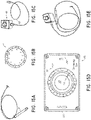
- a multi-pole synchronous pulmonary artery radiofrequency ablation catheter for de-sympathetic ablation in the pulmonary artery can include a catheter body 1 that has a distal end and a proximal end.
- the distal end can be provided with a flexible end 3 and the proximal end can be provided with a control handle 2.
- a pull wire can extend in the catheter body.
- the catheter body can be made of a polymer material, which is a poor heat conductor, so that it can avoid transmitting or reducing the amount of heat transferred from the electrodes to the blood flow contacting the catheter body, and thereby can better prevent the electrode from heating the blood flow.
- the flexible end 3 can include a proximal end and a distal end.
- An annular ring 4 can be arranged on the distal end.
- the flexible end 3 can be soft relative to the rest of the catheter body.
- the annular ring 4 can be provided with a plurality of electrodes 5, wherein each electrode 5 can be configured to sense or extract neural electrical signals, sense temperature and conduct ablation.
- Each of the electrodes can be connected to lead wires and temperature sensing wires, which extend through the catheter body to the control handle, thus is electrically connected to the control handle.
- One or more temperature sensing wires can be embedded under each electrode for precise monitoring of the temperature during ablation. Additionally, in some embodiments, the temperature sensing wires can be connected to a thermocouple connected to an inner facing side of the electrodes 5, or can include integrated thermocouples. Other configurations can also be used.
- ablation may be performed by the electrodes 5 using radiofrequency (RF) energy to ablate sympathetic nerve fibers to cause neuromodulation or disruption of sympathetic communication.
- RF radiofrequency
- the electrodes 5 may use ultrasonic energy to ablate sympathetic nerve fibers.
- the electrodes 5 use ultrasound (e.g., high-intensity focused ultrasound or low-intensity focused ultrasound) energy to selectively ablate sympathetic nerve fibers.
- the electrodes 5 use electroporation to modulate sympathetic nerve fibers.
- the electrodes 5, as used herein, shall not be limited to causing ablation, but also include devices that facilitate the modulation of nerves (e.g., partial or reversible ablation, blocking without ablation, or stimulation).
- the catheter may use agents offloaded at the location of the electrodes 5 to nerve fibers to modulate the nerve fibers (e.g., via chemoablation).
- Chemical agents used with chemoablation may, for example, include phenol, alcohol, or any other chemical agents that cause chemoablation of nerve fibers.
- cryotherapy is used.
- the catheter may use agents offloaded at the location of the electrodes 5 for cryoablation to selectively modulate (e.g., ablate) sympathetic nerve fibers.
- the catheter may use brachytherapy to modulate the nerve fibers.
- the catheter may further utilize any combination of RF energy, microwave energy, ultrasonic energy, focused ultrasound (e.g., HIFU, LIFU) energy, ionizing energy (such as X-ray, proton beam, gamma rays, electron beams, and alpha rays), electroporation, drug delivery, chemoablation, cryoablation, brachytherapy, or any other modality to cause disruption or neuromodulation (e.g., ablation, denervation, stimulation) of autonomic (e.g., sympathetic or parasympathetic) nerve fibers.
- RF energy e.g., microwave energy, ultrasonic energy, focused ultrasound (e.g., HIFU, LIFU) energy, ionizing energy (such as X-ray
- the neuromodulation system is used to modulate or disrupt sympathetic nerve fibers at one or more locations or target sites.
- the catheter may perform ablation in a circumferential or radial pattern (such as by using the annular ring 4), and/or the catheter may perform ablation at a plurality of points linearly spaced apart along a vessel length.
- the catheter performs ablation at one or more locations in any other pattern capable of causing disruption in the communication pathway of sympathetic nerve fibers (e.g., spiral patterns, zig-zag patterns, multiple linear patterns, etc.).
- the pattern can be continuous or non-continuous (e.g., intermittent).
- the ablation may be targeted at certain portions of the circumference of the vessels (e.g., half or portions less than half of the circumference).
- a shape memory wire can be arranged in the annular ring 4, and a distal end of the shape memory wire can extend to the distal end of the annular ring 4.
- the proximal end of the shape memory wire can be fixed to the distal end of the flexible end 3.
- the shape memory wire in the annular ring 4 can preferably be made of various shape memory alloys such as nickel-titanium alloy, stainless steel or titanium, with a diameter in the range of 0.25-0.5mm.
- the diameter of the annular ring 4 is in the range of 12-40 mm.
- the shape memory wire can be configured to bias the annular ring 4 to a desired diameter, such as in the range of 12-40 mm.
- the pull wire can be used to change or adjust the diameter of the annular ring 4 through a range of diameters including 12-40 mm or other ranges.
- the length of the flexible end 3 can be in the range of 30-80 mm and can be made of medical polymer materials such as fluorine, polyesters, polyurethane, polyamide and polyimide.
- a counterbore can be arranged on the distal end of the flexible end 3, the proximal end of the annular ring can be fixed in the counterbore, wherein the proximal end of the annular ring is a ground thin end.
- a pull wire can be embedded in the catheter body, and one end of the pull wire can be fixed to the control handle.
- the curvature of the flexible end 3 can be controlled by operating the control handle.
- one end of the pull wire can be fixed to a control button on the handle and the curvature of the flexible end 3 can be controlled by operating the button. This allows the operator to control the handle with one hand and adjust the curvature of the flexible end 3 easily, so that the electrodes 5 on the annular ring 4 can be pressed into contract with the pulmonary artery and achieve acceptable ablation of pulmonary artery intima.
- a counterbore can be made on the distal end of the flexible end 3, and its depth can be set according to actual needs, preferably with a depth in the range of 2-8 mm.
- the proximal end of the annular ring 4 can be a ground thin end, and an outer diameter of the ground thin end fits an inner diameter of the counterbore.
- the ground-thin end can be inserted into the flexible end 3 and can be fixed to the distal end of the flexible end 3 by bonding, welding or other suitable means, preferably by UV-curing adhesive. Excess glue may be used to seal the distal end of the flexible end 3 and the proximal end of the annular ring 4.
- Figure 1 shows a schematic structural diagram of the multi-pole synchronous pulmonary artery radiofrequency ablation catheter.
- the annular ring 4 can be arranged at the distal end of the flexible end 3.
- the annular ring 4 can be an annular structure, and the radius of the annular ring 4 can be effected with shape memory wire.
- the annular ring 4 can be provided with a plurality of electrodes 5.
- Each electrode 5 can be configured to extract or detect neural electrical signals, sense the temperature and conduct ablation.
- the number of electrodes 5 can vary from the range of 3 to 30, preferably 5 to 20.
- the electrodes 5 are made of platinum-iridium alloy, gold, stainless steel or nickel alloy.
- the electrode diameter can be generally 1.3-2.0 mm, and the length of the electrode 5 can be generally in the range of 1.2-4 mm, more suitably 2-3.5 mm. Edge space between the adjacent electrodes suitably can be in the range of 0.5-10 mm, more suitably 1-5 mm.
- the pull wire 8 can preferably be made of stainless steel or nickel-titanium. As shown in Figure 2 and Figure 3 , the distal end of the pull wire 8 extends through a hollow cavity 9 to the proximal end of the annular ring 4, and can be fixed to the distal end of the flexible end 3.
- the method used for fixing the pull wire 8 to the distal end of the flexible end 3 can be any known method in the prior art.
- a groove can be arranged on the distal end of the flexible end 3, and a connector 11 can be arranged in the groove.
- One end of the connector 11 can be connected to the pull wire 8 and the other end of the connector 11 can be connected to the shape memory wire 12.
- the connector 3 can be fixed to the distal end of the flexible end 3 by injecting glue such as UV-curing adhesive into the groove.
- a segment of pull wire 8 extends in the flexible end 3 and a segment of pull wire 8 extends in the catheter body 1.
- the pull wire can preferably be jacketed with a coil spring 13, and the coil spring 13 can be jacketed with a spring sleeve 14.
- the spring sleeve 14 may be made of any suitable material, preferably a polyimide material.
- the proximal end of the pull wire 8 can be fixed on or in the control handle 2, which can be provided with an adjustment apparatus, and the adjustment apparatus can be configured to adjust the curvature or the diameter of the annular ring 4.
- Lead wire 6, as shown in Figure 2 and Figure 3 extends through the lead wire cavity 10 to the lead wire cavity of the annular ring 4.
- the distal end of the lead wire 6 can be connected to electrode 5.
- the distal end of the lead wire 6 can be fixed to electrode 5 by welding.
- the catheter includes one lead wire 6 for each of the electrodes 5.
- the distal end of the temperature sensing wire 7 can be embedded under the electrode 5 and the distal end of the temperature sensing wire 7 can be fixed on electrode 5 by bonding, welding or other suitable means.
- the temperature sensing wire 7 can extend into the catheter body 1 in the lead wire cavity 10 of the flexible end 3 and then extend out from the control handle 2 and can be connected to a temperature control device.
- the catheter includes one temperature sensing wire 7 for each of the electrodes 5.
- the pull wire 8 can be operated through the control handle 2 in order to deflect the flexible end 3, thereby providing enhanced control for the user when positioning the annular ring 4 in a desired location, such as an orifice of the pulmonary artery.
- the electrodes 5 can be energized for performing ablation on pulmonary artery intima.
- the multi-electrode design can improve the efficacy and safety of ablation, and achieve signal analysis and preferably simultaneous ablation by a plurality of electrodes. This can also improve target accuracy, achieve timely judgment of ablation effect and save operation time.
- the electrodes can be individually activated to perform ablation at selected sites. This can be a benefit because in some methods of treatment described below, ablation can be performed at selected sites, less than the entire circumferential surface of certain anatomy.
- a multi-pole synchronous pulmonary artery radiofrequency ablation catheter comprises a control handle 2, a catheter body 1, and an annular ring 4.
- the control handle 2 can be provided with an adjustment apparatus, the catheter body 1 can be hollow, and a cavity can be arranged in the catheter body 1.
- One or more lead wires 6, temperature sensing wires 7, and a pull wire 8 can be arranged in cavity.
- One end of catheter body can be flexible, and the flexible end 3 can be connected to the annular ring 4.
- the other end of the catheter body can be connected to the control handle 2.
- One end of the pull wire 8 can be connected to the flexible end 3, and the other end of the pull wire 8 can be connected to the adjustment apparatus of the control handle, and the adjustment apparatus adjusts the tension of the pull wire 3 to control the curvature of the flexible end. This allows the operator to control the handle with one hand and adjust the curvature of the flexible end 3 easily.
- the electrodes 5 of the annular ring 4 can be pressed against to better contact an inner surface of a desired anatomy, such as a pulmonary artery, so as to enhance ablation of pulmonary artery intima.
- a shape memory wire 12 can be arranged in the annular ring 4. One end of the shape memory wire 12 can extend to the end of the annular ring 4, and the other end of the shape memory wire 12 goes through the root of the annular ring 4 and can be fixed on the flexible end 3 of the catheter body.
- the annular ring 4 can also be provided with an electrode group.
- Each electrode 5 can be connected to a lead wire 6 and a temperature sensing wire 7 and can be configured to extract or detect the nerve electrical signals, sense the temperature and conduct ablation.
- the lead wires 6 and temperature sensing wires 7 can extend through the catheter body 1 and can be electrically connected to the control handle 2.
- the control handle 2 can be connected to an external temperature control device.
- the annular ring electrodes 5 can be made of a material selected from a group consisting of platinum-iridium alloy, gold, stainless steel and nickel alloy material, with the number in the range of 3-30, a diameter in the range of 1.3-2.0 mm, a length in the range of 1.2-4 mm and an edge space between adjacent electrodes in the range of 0.5-10 mm.
- the flexible end 3 of the catheter body can have a counterbore 32.
- An outer diameter of the root of the annular ring 4 can fit an inner diameter of the counterbore 32.
- the root of the annular ring 4 can be inserted into the counterbore 32 and fixed.
- the flexible end 3 of the catheter body can be provided with a groove.
- a connector 11 can be arranged in the groove.
- One end of the connector can be connected to the pull wire 8 and the other end of the connector can be connected to the shape memory wire 12.
- the shape memory wire 12 can be made of shape memory alloy such as nickel-titanium alloy, stainless steel or titanium, with a diameter in the range of 0.25-0.5 mm.
- the diameter of the annular ring 4 can be in the range of 12-40 mm.
- 10 electrodes are arranged on the annular ring, and the width of naked (exposed) side of electrodes can be 0.75 mm, and the space there between can be 5 mm.
- the flexible end 3 of the catheter body can be made of medical polymer materials such as fluorine, polyesters, polyurethane, polyamide and polyimide, with a length in the range of 30 mm to 80 mm.
- the connection can be via UV-curing adhesive.
- the joint between the flexible end of the catheter body and the annular ring can be sealed.
- the pull wire 8 can be made of stainless steel or nickel-titanium alloy.
- the pull wire 8 can be jacketed with a coil spring 13, and the coil spring 13 can be jacketed with a spring sleeve 14 made of polyimide material.
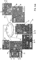
- Example 3 is similar to Example 1 and Example 2, and the differences can include an infusion tube 22 arranged in the catheter body, a group of evenly distributed through holes 15 ( Figure 4 ) arranged on one or more of the electrodes 5, with a bore diameter of 1 ⁇ m.
- One end of the infusion tube 22 can be connected to the electrodes 5 through the annular ring 4 such that fluid diffuses out from the through holes 15 on each of the electrodes 5.
- the annular ring 4 can include or define at least one lumen 24 extending between a proximal end of the annular ring 4 and to the through holes 15 so as to form a closed fluidic connection.
- a distal end of the infusion tube 22 can be connected to the proximal end of the lumen 24 in the annular ring 4.
- the other end of the infusion tube 22 can be connected to a transfusion system, such as a constant-flux pump or other known pumps.
- the transfused liquid can be saline.
- the cold saline (4 °C) perfusion can help decrease local temperature.
- the saline can automatically diffuse from the through holes 15, and thus can allow the local temperature to be controlled to a desired temperature, such as to below 60 °C and thereby protect the vascular intima.
- FIG. 5 is a schematic diagram of a human heart and surrounding vasculature, which can be an environment in which the catheter of Figures 1-4 can be used to perform ablation treatments such as, for example, but without limitation, denervation of the pulmonary artery.
- ablation treatments such as, for example, but without limitation, denervation of the pulmonary artery.
- access to the inner walls of the main pulmonary artery 502 as well as the left pulmonary artery 504 and right pulmonary artery 506 can be achieved by passing a catheter, using well known techniques, into a femoral vein, upwardly into the inferior vena cava 508 (lower left hand corner of Figure 5 ).
- main pulmonary artery (MPA) 502 includes the proximal end of the main pulmonary artery which is the furthest upstream end of the main pulmonary artery 502, at the pulmonary semilunar valve 514, up to the bifurcation of the main pulmonary artery.
- the distal portion of the MPA 502 includes the portions of the MPA 502 near the bifurcation of the MPA 502 into the left and right pulmonary arteries (LPA 504, RPA 506).
- the proximal ends of the RPA 506 and LPA 504 are those ends of the LPA 504 and RPA 506 which are adjacent and connected to the distal end of the MPA 502.
- the distal direction along the LPA 504 and RPA 506 would be the downstream direction of blood flow through the LPA 504 and RPA 506 toward the left and right lungs, respectively.
- a catheter can be used to provide access to the proximal and distal portions of the MPA 502 as well as the proximal and distal portions of the LPA 504 and RPA 506.
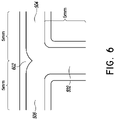
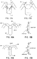
- Figure 6 is a schematic diagram of the "trunk" of the pulmonary artery.
- the "trunk" of the MPA 502 is intended to include at least the distal portion of the MPA 502 and the proximal portions of the LPA 504 and RPA 506.
- Figure 6 also includes a schematic representation of a carina 602 at the branch of the LPA 504 and RPA 506 from the MPA 502.
- the trunk of the pulmonary artery of certain animals can include concentrated bundles of sympathetic nerves extending from the MPA 502 into the LPA 504 and RPA 506.
- the sympathetic nerves bifurcate from this area of higher concentration into the anterior side of the proximal portions of the LPA 504 and RPA 506. In the area of these proximal portions, it has also been discovered that higher concentrations of the sympathetic nerves extend upwardly and toward the posterior side of the LPA 504 and RPA 506.
- ablation is performed in the distal portion of the MPA 502 and the proximal portions of the LPA 504 and RPA 506.
- ablation is preferentially performed on the anterior side of the inner walls of these structures.
- ablation is performed preferentially on the anterior side of the proximal portion of the MPA 502 and on the anterior side and an upper portion of the proximal portions of the LPA 504 and RPA 506, such as at approximately the upper conjunctive site of the distal portion of the MPA 502 at the LPA 504 and RPA 506.
- a dog was anesthetized with sodium pentobarbital (60 mg per kg, intraperitoneal injection). The chest was excised and opened carefully. The whole pulmonary artery was removed from the chest, with particular attention to avoid the injury of adventitia. In one dog, the pulmonary artery was longitudinally cut along the blood flow direction from the orifice of the main pulmonary artery (the proximal portion of the main pulmonary artery) toward the right and left branches. Then, a vernier focusing camera was used to take pictures in order to identify whether there is a visible difference in the surface of the pulmonary artery between different segments.
- connective tissue was manually dissected away from the pulmonary artery using fine microdissection scissors, under the guidance of stereomicroscope. During this procedure, great care was taken to avoid stripping off the adventitia and possible damage to the perivascular nerves. Vessels were stored at -70 °C for further staining.
- Frozen vessels were processed in paraffin wax and fixed in 4% paraformaldehyde for 30 minutes and then incubated at 0.5% Pontamine Sky Blue (Sigma-Aldrich, St. Louis, MO) in phosphate-buffered saline (PBS) for 30 minutes to reduce background fluorescence. This was followed by 1 hour at room temperature in a blocking solution of 4% normal goat serum/0.3% Triton X-100 in PBS, then overnight at 4 °C in blocking solution containing an affinity-purified polyclonal antibody against tyrosine hydroxylase (Temecula, CA).
- PBS phosphate-buffered saline
- Vessel segments were then washed in PBS and incubated for 1 hour with secondary antibody (Invitrogen, Carlsbad, CA), washed again and positioned on a glass slide. Preparations remained immersed in PBS during image acquisition to maintain hydration and preserve vessel morphology.
- secondary antibody Invitrogen, Carlsbad, CA
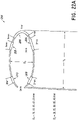
- FIG. 6 schematically illustrates, not to scale, a 5 mm segment of the distal portion of the MPA and 5 mm long proximal portions of the LPA and RPA.
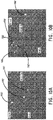
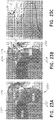
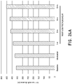
- transverse slices (2 ⁇ m of thickness) of the vessels were cut at 1.6 mm intervals and are identified in the description set forth below in accordance with the labels of Figure 8 (A1, A2, A3, A4, A5, A6, A7, A8, A9, A10, A11, A12). Care was taken to keep the luminal morphology of slices consistent with the vessel contour, in order to precisely position the location of nerves. The slices were examined by a pathologist.
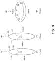
- the minor and major radii of sympathetical axons in the main pulmonary artery were 85 ⁇ 2 ⁇ m and 175 ⁇ 14 ⁇ m, compared to 65 ⁇ 3 ⁇ m and 105 ⁇ 12 ⁇ m in the left pulmonary artery or 51 ⁇ 2 ⁇ m and 86 ⁇ 8 ⁇ m in the right pulmonary artery, respectively, resulting in significant differences in surface area of axons between the main pulmonary artery and the LPA and RPA ( Figure 9 ).
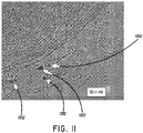
- subsegment S6 in level A9 ( Figure 11 ) of the MPA revealed that a bundle or main bundle of sympathetical nerves originate from approximately the middle of the anterior wall of the distal portion of the main pulmonary artery and that this main bundle is bifurcated to the left and right pulmonary arteries.
- This discovery provides a basis for more effective denervation of the pulmonary artery. For example, by selectively ablating only portions of the main pulmonary artery and the left and right pulmonary arteries, a higher success rate of denervation can be achieved with less unnecessary tissue damage. Such denervation can provide significant benefits in the treatment of diseases such as pulmonary hypertension, as described below.
- the lung receives axons from principal sympathetic neurons residing in the middle and inferior cervical and the first five thoracic ganglia (including the stellate ganglion), and the vasculature is the major sympathetic target in the lung.
- Sympathetic nerve stimulation increases pulmonary vascular resistance and decreases compliance, which is mediated by noradrenaline via a-adrenoreceptors, primarily of the al-subtype.
- sympathetic noradrenergic innervation density is highest at the large extra-pulmonary and hilar blood vessels, both arteries and veins, and then decreases toward the periphery. This is in marked contrast to many other organs, in which the highest innervation density is found at the level of the smallest arterioles.
- Such distribution varies from species to species with regard to the extent to which the sympathetic noradrenergic axons reach into the lung. In guinea pigs, rabbits, sheep, cats, dogs, and humans, small arteries down to 50 ⁇ m in diameter are innervated, whereas in rats, mice, hedgehogs, and badgers, noradrenergic innervation stops close to the lung.
- noradrenergic and NPY-containing fibers have been noted around pulmonary arteries of several species, but only a few studies used double-labeling techniques to evaluate the extent of colocalization.
- principally all noradrenergic fibers innervating pulmonary arteries and veins contain NPY and, in addition, dynorphin, a neuropeptide of the opioid family.
- pulmonary vascular innervation differs markedly from that of skin arteries in the same species, wherein three different combinations of noradrenaline, NPY, and dynorphin are used by sympathetic axons. Each of these populations is restricted to a specific segment of the arterial tree in the skin.
- noradrenergic and NPY-containing fibers do not match 1:1 in the lung either, as there is a minor population of axons innervating guinea pig pulmonary arteries and veins that contains NPY plus vasoactive intestinal peptide (VIP) but not noradrenaline. It remains to be clarified whether this less-frequent fiber population represents the non-noradrenergic neurons projecting to the guinea pig lung or originates from other systems.
- VIP vasoactive intestinal peptide
- IPAH idiopathic pulmonary arterial hypertension
- PAP mean pulmonary artery pressure
- PVR pulmonary vascular resistance
- the pathogenesis of IPAH was believed to be due to imbalance between locally produced vasodilators and vasoconstrictors.
- vascular wall remodeling also contributed to elevated PVR.
- the role of neural reflex in the mediation and development of IPAH has not been specifically investigated.
- the present animal study described above demonstrates that the PADN procedure can reduce or completely abolish elevations of PAP induced by balloon occlusion at interlobar segments, but not at the basal trunk.
- a human study was conducted. Prior to enrollment, all 21 patients received a diuretic (hydrochlorothiazide at a dose of 12.5 mg to 25 mg, once daily, and/or spironolactone at a dose of 20 mg to 40 mg, once daily) and beraprost (120 mg, 4 times daily) (Table 1), with either sildenafil (20 mg, 3 times a day) or bosentan (120 mg, twice daily) or digoxin (0.125 mg, once daily). Functional capacity of the patients was determined by a 6-minute walk test (6MWT), followed by an assessment of dyspnea using the Borg scale. The 6MWT was performed at 1 week, 1 month, 2 months, and 3 months following the PADN procedure. The WHO classification at rest and during exercise was recorded by a physician who was blinded to the study design.
- 6MWT 6-minute walk test
- Echocardiography was performed at 1 week, 1 month, 2 months, and 3 months following the procedure. Echocardiographic studies were done using a Vivid 7 ultrasound system with a standard imaging transducer (General Electric Co., Easton Turnpike, CT, US). All of the echocardiograms were performed and interpreted in the Medical University Echocardiographic Laboratory. All of the measurements were performed following the recommendations of the American Society of Echocardiography. Digital echocardiographic data that contained a minimum of 3 consecutive beats (or 5 beats in cases of atrial fibrillation) were acquired and stored. RV systolic pressure is equal to systolic PAP in the absence of pulmonary stenosis.
- Systolic PAP is equal to the sum of right atrial (RA) pressure and the RV to RA pressure gradient during systole.
- RA pressure was estimated based on the echocardiographic features of the inferior vena cava and assigned a standard value.
- the RV to RA pressure gradient was calculated as 4v t 2 using the modified Bernoulli equation, where v t is the velocity of the tricuspid regurgitation jet in m/s.
- the mean PAP was estimated according to the velocity of the pulmonary regurgitation jet in m/s.
- the tricuspid excursion index (TEI) is defined as (A - B)/B, where A is the time interval between the end and the onset of tricuspid annular diastolic velocity, and B is the duration of tricuspid annular systolic velocity (or the RV ejection time).
- PA compliance for patients was calculated as stroke volume divided by pulse pressure (systolic PAP minus diastolic PAP).
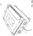
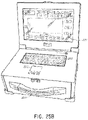
- the PADN procedure was performed with a dedicated 7.5F multiple-function (temperature-sensor and ablation) catheter which comprised two parts, a catheter shaft 3 and handle 2 ( Figure 15A ) which is an embodiment of the catheter illustrated in Figures 1-4 .
- the catheter of Figure 15A had a tapered (to 5F) annular ring 4 with 10 pre-mounted electrodes 5 (E1-E10) each separated by 2 mm, however, other spacings can also be used.
- the electrodes 5 have been numbered, as shown in Figure 15B , with the distal-most electrode 5 identified as electrode El and the proximal-most electrode 5 identified as electrode E10.
- the annular ring 4 or (“circular tip”) can be constructed so as to be biased into an annular/circular shape, such as the circular shape illustrated in Figure 15B and Figure 1 to have any desired outer diameter.
- the annular ring 4 can be configured to be biased into a circular shape having an outer diameter of 20 mm, 25 mm, 30 mm, 35 mm, 40 mm, 45 mm, or other diameters.
- a kit containing the catheter of Figure 1 can include a plurality of different annular rings 4 configured to be biased to a plurality of different outer diameters, such as those noted above, or other diameters.
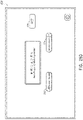
- a controller or "connect box” can be connected to the handle 2 of the catheter for providing ablation energy.
- an ablation controller 100 can be configured to provide ablation energy to each of the electrodes E1-E10.
- the controller 100 includes a selector knob 102 configured to allow a user to select activation of all the electrodes E1-E10, or selective actuation of individual ones of the electrodes E1-E10, one at a time.
- the selector knob 102 includes a position indicator 104 which, by rotating the knob 102 can be aligned with indicia corresponding to the electrodes E1-E10.
- the indicia on the controller 100 includes the numbers 1-10 as well as a position identified as "OFF” and a position identified as "NULL.”
- the connect cable 106 can include a plurality of wires, for example, ten wires which correspond to the lead wire 6 described above with reference to Figures 1-4 , each one of which is individually connected to respective electrodes E1-E10.
- the controller 100 can include a physical switch for creating an electrical connection between a source of RF energy and a desired one of the electrodes E1-E10.
- An electrode (not shown) can be directly connected to the knob 102 with additional contacts (not shown) disposed around the electrode at approximately the positions identified as 1 through 10 on the controller 100.
- rotation of the knob 102 will connect an internal electrode (not shown) with the contacts aligned with each one of the positions 1-10.
- the controller 100 can be configured to provide the desired amount of ablation energy when a circuit is created by the alignment of the position indicator 104 with the corresponding position (1 through 10) on the controller 100 thereby delivering electrical energy to the selected one of the electrodes E1-E10 causing electrical energy to pass through the selected electrode 5 into any conductive material in contact with that selected electrode.
- the electrodes E1-E10 can be in contact with an inner wall of the pulmonary artery trunk thereby allowing electrical energy from one of the electrodes E1-E10 to flow through the tissue of the inner wall of the pulmonary artery, described in greater detail below.
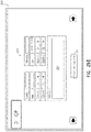
- the controller 100 can include a plurality of ports.
- the controller 100 can include a catheter port 120, which can be configured for creating a fluidic connection to the annular ring for purposes of providing a flow of saline to the annular ring 4.
- the controller 100 can also include an RF port 122 configured to connect to any known radiofrequency generator used with regard to ablation procedures.
- controller 100 can include an "ECG" port 124 configured for connection with standard ECG monitoring equipment.
- the connect cable 106 can also include wires or conduits for transmitting data through the RF port 124.
- the RF port 122 can be connected to a source of RF energy (not shown).
- One or more wires can connect the port 122 to a contact on the end of an electrode connected to the selector knob 102.
- the ten wires can be configured to deliver RF electrical energy to the electrodes E1-E10 each of which can be connected to contacts (not shown) associated with the selector positions 1-10 disposed around the periphery of the selector knob 102.
- the electrode connected to the rotating selector knob 102 can be moved into contact with the electrical contacts associated with each of the positions 1-10 thereby creating a circuit connecting the electrical energy entering the controller 100 through the port 122 with the associated lead wire 6 for conducting electrical energy to the desired electrode E1-E10.
- a method for treating pulmonary hypertension which method does not form part of the invention and is shown for illustrative purposes only, can include a step of identifying the position of the pulmonary trunk of the patient using angiography.
- baseline pulmonary artery angiography can be performed to identify the position of the pulmonary artery bifurcation from the main pulmonary artery into the left and right pulmonary arteries.
- the baseline pulmonary artery angiography can be used to determine the diameter of the portions of the pulmonary artery trunk upon which ablation is desired.
- the appropriate diameter of the annular ring 4 can be determined based on the determined diameters of the pulmonary artery trunk noted above.
- an annular ring 4 having a biased diameter slightly larger than the diameters of the targeted anatomy can be used so as to enhance the contact between the electrodes 5 and the inner surface of the targeted anatomy.
- the annular ring 4 when the annular ring 4 is moved out of a sheath 1602 and allowed to expand into its biased circumferential configuration which has an outer diameter slightly larger than the inner diameter of the targeted portions of the pulmonary artery trunk, the bias of the annular ring 4 will assist in pressing the electrodes 5 into contact with the targeted tissue.
- a method can include a step of positioning a catheter in a pulmonary artery trunk.
- the sheath 1602 can be inserted through the femoral vein and advanced to the main pulmonary artery, as shown in Figure 16A .
- a catheter such as the catheter illustrated in Figure 1 and Figures 15A-15E can be advanced along the sheath 1602 shown in Figure 16A to the location of the pulmonary artery trunk.
- the sheath 1602 With the distal end of the catheter maintained in place, the sheath 1602 can be withdrawn. It may be necessary to push on the catheter to maintain its position with the portion of the catheter forming the annular ring 4 held within the pulmonary artery trunk.
- the annular ring 4 can adopt the shape and diameter to which it is biased.
- the annular ring 4 can be positioned at the proximal portion of the left pulmonary artery, such as at the ostium. In some embodiments, this initial position can be within a range of approximately 5 mm from the orifice of the left pulmonary artery or within a range of 2 mm, as illustrated in Figure 16D .
- the desired one or plurality of the electrodes E1-E10 can be selectively energized so as to perform ablation at the desired location on the interior surface of the left pulmonary artery.
- it may be more effective to selectively ablate the posterior wall of the left pulmonary artery, so as to achieve at least some sympathetic denervation of the left pulmonary artery and the proximal portion thereof, such as within 2 mm or 5 mm of the ostium of the left pulmonary artery.
- the annular ring 4 can then be rotated, such as in the counterclockwise direction, by rotating and withdrawing the handle 2 in order to reposition the annular ring 4 into the distal portion of the main pulmonary artery such as at the bifurcation area.
- the annular ring 4 can be positioned within about 5 mm of the bifurcation in the pulmonary artery trunk. Ablation can then be performed using the desired one or plurality of the electrodes E1-E10.
- the selected one or plurality of electrodes E1-E10 can be energized to achieve the desired sympathetic denervation of the distal portion of the main pulmonary artery.
- further rotating and pushing the handle 2 can be performed until the annular ring 4 is positioned in the proximal portion of the right pulmonary artery, such as at the ostium. In some embodiments, this position can be within 5 mm of the ostium of the right pulmonary artery. Further, in some embodiments, this position can be within 2 mm of the ostium of the right pulmonary artery.
- the desired one or plurality of electrodes E1-E10 can be energized so as to achieve at least some sympathetic denervation in the proximal portion of the right pulmonary artery.
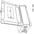
- a method for treating pulmonary hypertension can also include a step of confirming the appropriate contact between the electrodes E1-E10 and the endovascular surface corresponding to the three positions noted above. For example, in some embodiments, such confirmation can be performed by determining if there is strong manual resistance when attempting to rotate the handle 2. Additionally, it can be determined if the annular ring 4 cannot be advanced distally, resulting in the deformation of the catheter as illustrated in Figure 16G or if there is ease in withdrawing proximally, resulting in the deformation of the catheter illustrated in Figure 16H . Additionally, confirmation can be performed using angiographic confirmation.
- a method for treating pulmonary hypertension can include the sequential energization of each of the electrodes E1-E10.
- a method for treating pulmonary hypertension or for performing pulmonary denervation can include the step of repositioning the annular ring 4 so as to shift the location of the electrodes E1-E10 and then repeating energization of all of the electrodes E1-E10. As such, a more complete denervation of the entire inner surface of the associated vessel can be achieved.
- any desired energy levels or temperatures can be used for performing ablation using the electrodes E1-E10 noted above.
- ablation can be performed at temperatures above 50 °C, drawing an electrical load of 8-10 W for a duration of 60-120s.
- the method of treatment of pulmonary hypertension or the method of sympathetic denervation of the pulmonary artery can be performed with a patient anesthetized but conscious. Thus, any ablation procedure can be stopped if the patient complained of intolerable chest pain.
- EKG and hemodynamic pressure can be monitored and continuously recorded throughout the method.
- success was defined as a reduction in the mean PAP ⁇ 10 mmHg (as measured by the Swan-Ganz catheter). During the study, there were no complications. Additionally, the patients were monitored in the Coronary Care Unit (CCU) for at least 24 hours after the PADN procedure was performed.
- CCU Coronary Care Unit
- a dedicated 7.5 F triple-function catheter can be used, which can include a tapered annular ring 4 with 10 electrodes 5 (each has 0.75 mm electrode-width and is separated by 2 mm, pre-mounted. Electrodes are connected with a connect-cable 106 and a connect-box/controller 100. There are 10 positions of the knob 102 ( Figure 15D ) on the surface of controller 100, and each is associated with one of the electrodes E1-E10 on the annular ring 4 of the ablation catheter. Sequential ablation can be performed by turning the knob 102 as desired after the whole system is set up. In certain embodiments, ablation is interrupted while switching ablation from one electrode to another.
- ablation of the distal portion of the main pulmonary artery can be performed preferentially on the anterior side thereof.
- ablation can be performed at the positions identified as M1, M2, M3, M4, and M5.
- the position identified as M1 is at the "6 o'clock" position in the distal portion of the main pulmonary artery.
- the positions identified as M3 and M5 are the sites where the anterior wall of the main pulmonary artery connects to the left and right pulmonary arteries, respectively.
- the positions identified as M2 and M4 correspond to the "5 o'clock” and the "7 o'clock” positions on the anterior side of the distal portion of the main pulmonary artery.
- sympathetic denervation in the left and right pulmonary arteries can be performed, preferentially, at approximately the middle of the anterior wall of the proximal portion of the left pulmonary artery (L1) and at approximately the upper conjunctive site of the distal portion of the main pulmonary artery in the left pulmonary artery (L2).
- ablation can be preferentially performed at a point approximately at the middle anterior wall of the proximal portion of the right pulmonary artery (L3) and at approximately the upper conjunctive site of the distal portion of the main pulmonary artery and the right pulmonary artery (L4).
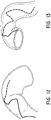
- sympathetic denervation can be performed, for example, for treatment of pulmonary hypertension associated with a pulmonary duct artery (PDA) 1802.
- a pulmonary duct artery usually connects the descending aorta with the left pulmonary artery 504, as shown in Figure 5 .
- the left pulmonary artery can be significantly larger than the right pulmonary artery.
- ablation can be performed at a position proximal to connection between the left pulmonary artery and the pulmonary duct artery, identified as "Level A” in Figure 18A .
- the annular ring 4 can be positioned at a position corresponding to "Level A" of Figure 18B . Ablation can then be performed around part or all of the interior wall of the left pulmonary artery at that location.
- ablation can be preferentially performed on the anterior wall of the left pulmonary artery proximal to the proximal end of the pulmonary duct artery.
- ablation can be performed at four or more sites, such as those identified as sites L11, L12, L13, L14.
- sites L11, L12, L13, L14 As illustrated in Figure 18B , position L11 corresponds to "12 o'clock”, position L12 corresponds to "2 o'clock”, position L13 corresponds to "3 o'clock”, and position L14 corresponds to "6 o'clock.” Other positions can also be used.
- ablation can also be performed at positions M1-M5 illustrated in Figure 17A and positions L1-L4 of Figure 17B .
- a method for sympathetic denervation can be used for treating pulmonary hypertension resulting from unilateral chronic thrombotic embolism.
- a patient suffering from unilateral CTEH can have an occluded right pulmonary artery.
- the RPA can be significantly enlarged as illustrated on the left side of Figure 19A .
- ablation can be performed at the position identified as "Level B" in Figure 19A .
- Ablation can be performed at one or a plurality of locations along the inner surface of the right pulmonary artery at the position of Level B, or other positions. Additionally, ablation can be preferentially performed on a plurality of points along the anterior wall of the right pulmonary artery at the position of Level B.
- the positions identified in Figure 19B can be considered such as position L21 corresponding to "12 o'clock", position L22 corresponding to "2 o'clock", position L23 corresponding to "3 o'clock", and position L24 corresponding to "6 o'clock.” Additionally, in some embodiments, ablation can also be performed at positions M1-M5 illustrated in Figure 17A and positions L1 and L2 illustrated in Figure 17B .
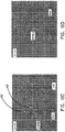
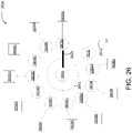
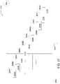
- FIG. 20 further embodiments of treatments for pulmonary hypertension can include selected ablation of portions of the pulmonary artery trunk, at fewer ablation sites than some of the embodiments described above.
- Figure 20 identifies "Level C" for reference with regard to the ablation sites identified in Figure 21 .
- an enlarged schematic diagram of "Level C" identified in Figure 20 identifies a plurality of that ablation sites, b 1 , b 2 , b 3 which are grouped in a portion of the pulmonary artery trunk proximal to a left side lateral wall at the upper end of the main pulmonary artery and proximal to a lower wall of the proximal portion of the left pulmonary artery, where those portions meet.
- the ablation site b 1 is disposed at approximately a left lateral apex of the distal end of the main pulmonary artery, which connects with a lower wall of the proximal end of the left pulmonary artery.
- the ablation sites b 2 , b 3 are disposed, along or substantially along the "Level C" identified in Figure 20 , on the anterior and posterior sides, respectively, of the ablation site b 1 .
- These ablation sites b 1 , b 2 , and b 3 may be targeted to ablate a particular bundled cluster of sympathetical nerves on the left lateral side of the distal end of the main pulmonary artery.
- These bundled clusters may be approximately 5 mm above the pulmonary valve 514 ( Figure 5 ) but under the carina 602 ( Figure 6 ).
- Figure 22A illustrates a further embodiment of the annular ring 4 illustrated and described above with reference to Figure 1 and Figure 15B .
- the embodiment of the annular ring 4 illustrated in Figure 22A is identified with the reference 204.
- the annular ring 204 illustrated in Figure 22A can be constructed in accordance with the description set forth above with regard to the annular ring 4 and can be used with the handheld device 1 ( Figure 1 ), except with regard to the differences described below.
- the annular ring 204 can have a fewer number of electrodes than that included in the annular ring 4 described above.
- the annular ring 204 includes five electrodes, 200, 205, 206, 208, 210.
- the annular ring 204 is provided with and configured to conform to (or be biased to) an oval shape, when in its deployed/relaxed state. In its deployed/relaxed state, the annular ring 204 may be substantially planar. Also, in its deployed/relaxed state, the annular ring 204 may be substantially orthogonal, and optionally perpendicular, to a portion of the flexible end 3 of the catheter body connected with the annular ring 204.
- the annular ring 204 in its deployed state, can have a diameter D 1 along its major axis.
- the diameter D 1 is larger than the second diameter D 2 along the minor axis of the annular ring 204.
- Such a configuration provides the angular ring 204 with an oval shape, when in its deployed state.
- the electrodes 200, 205, 206, 208, 210 of the annular ring 204 can be sized in space with the dimensions identified in Figure 22A , or other dimensions.
- the annular ring 204 may be elliptical and optionally substantially planar. Optionally, such an elliptical ring can be less than a complete loop.
- the distal end of the annular ring 204 may not curve 360 degrees back to the proximal end of the annular ring but may curve around by an angle of less than 360 degrees (for example by curving at an angle of 270 degrees to 359 degrees).
- the proximal end of the annular ring may be separated by a distance of 3 mm as illustrated in Figure 22A due to not curving 360 degrees back to the proximal end of the annular ring 204.
- the electrodes 206, 205, 208 can be arranged and sized to provide for selective ablation of a pulmonary artery corresponding to the ablation sites b 1 , b 2 , b 3 described above with reference to Figure 21 . Further, the electrodes 206, 205, 208 can have different sizes. In some embodiments, the electrode 206, configured and sized to accommodate denervation of the site b 1 can be larger than the electrodes 205, 208. Further, in some embodiments, the electrode 205 can be larger than the electrode 208.
- the electrode 206 for ablation at b 1 may be 4 mm long while the electrode 205 for ablation at b 2 may be 3 mm long and the electrode 208 for ablation at b 3 may be 2 mm long.
- Other arrangements, configurations, and sizes can also be used.
- the electrode 206, for ablation at b 1, may be located at an end of diameter D 1 and/or straddle an apex of the major axis of annular ring 204.
- the annular ring 204 can be constructed with several sizes.
- Figure 22A includes examples of diameters D 1 , D 2 that can be used for five different sizes of the annular ring 204.
- the diameters D 1 , D 2 for those five different sizes can be combined in the following listed pairs of diameters (in millimeters), which are listed in the format (D 1 , D 2 ): (25, 20), (30, 25), (35, 30), (40, 35), and (50, 45).
- the diameter D 1 is 5 mm larger than the diameter D 2 .
- Other sizes and proportions can also be used.
- PAs pulmonary arteries
- effective reduction of PA hypertension can be achieved by ablating at 3 sites in the left side only, such as approximately at the locations b 1 , b 2 , b 3 identified above with reference to Figure 21 . Additional ablations can be omitted. Thus, in some embodiments, ablations can be carried out at or in the vicinity of the ablations locations b 1 , b 2 , b 3 and further ablations be avoided or omitted.
- Figure 22B illustrates a further embodiment of the annular ring 204 illustrated and described above with reference to Figure 22A .
- the embodiment of the annular ring 204 illustrated in Figure 22B is identified with the reference 220.
- the annular ring 220 in its deployed state, can have a diameter D 3 along its major axis.
- the diameter D 3 is larger than the second diameter D 4 along the minor axis of the annular ring 220.
- Such a configuration provides the angular ring 220 with an oval shape, when in its deployed state.
- Figure 22B includes examples of diameters D 3 , D 4 that can be used for five different sizes of the annular ring 220.
- the diameters D 3 , D 4 for those five different sizes can be combined in the following listed pairs of diameters (in millimeters), which are listed in the format (D 3 , D 4 ): (25, 20), (30, 25), (35, 30), (40, 35), and (50, 45).
- the diameter D 3 is 5 mm larger than the diameter D 4 .
- Other sizes and proportions can also be used.
- the annular ring 220 may be configured for the ablation of three sites with electrodes 206, 205, and 208 at approximately at the locations b 1 , b 2 , b 3 identified above with reference to Figure 21 and Figure 22A .
- the electrode 206, for ablation at b 1 may be located at an end of diameter D 3 and/or straddle an apex of the major axis of annular ring 220.
- the electrodes 208, 206, and 205 of the annular ring 220 can be sized in space with the dimensions identified in Figure 22A , or other dimensions.
- the tissue temperature is raised to 50 °C, (range 48°-52°), for example, by applying RF energy to each of the 3 sites b 1 , b 2 , b 3 for 2 minutes each.
- additional ablations can be omitted.
- the generator can be configured to, and can be operated to, deliver 3-15 watts of RF energy.
- an immediate decrease in PA blood pressure of at least about 10% can be achieved by ablating the three sites b 1 , b 2 , b 3 as described above.
- Such a physiological change can serve as immediate feedback and can be used to further guide treatment.
- the efficacy of the PADN procedure versus standard pharmacotherapy for the treatment of PAH with different etiologies was investigated in an additional study.
- 28 patients with PAH were assigned to standard medication and the PADN procedure sequentially.
- the PADN procedure was associated with significant improvements in 6-minute walk distance (6MWD) and hemodynamics six months following the PADN procedure.
- the PADN procedure had less frequent PAH-related events after 6- to 12-month following the PADN procedure.
- PAP resting mean PAP
- PH pulmonary hypertension
- LHD left heart disease
- PVR pulmonary vessel resistance
- PAOP pulmonary arterial obstructive pressure
- a wash-out consisting of 5 half-lives was performed for all the patients. All the patients who met the above inclusion and exclusion criteria were included and entered into the first wash-out period (defined as stopping all medications for at least 5 half-lives, with the exception of warfarin) as right heart catheterization and adenosine test for all patients were not performed before study. Warfarin was continuously prescribed. Otherwise, aspirin (100 mg/d) and Plavix (75 mg/d) were prescribed instead of warfarin for the patients who were intolerable to warfarin. Immediately after the PADN procedure, the standard medication for PAH were stopped for all the patients.
- the drugs were prescribed again and continued for 6 months (Medication treatment). The selection of drugs was left to the physician's discretion based on comprehensive analysis. After 6 months, the patients underwent a second wash-out period of 5 half-lives in order to establish the PADN procedure as a standard alone therapy.
- a 7F flow-directed Swan-Ganz catheter (Edwards, USA) was inserted percutaneously in the patients who were under local anesthesia into an internal jugular vein for the measurements of the resting RAP, sRVP, sPAP, mPAP, PAOP, and cardiac output (CO) values.
- the PVR [ (mPAP-PAOP)/CO] was then calculated. All the measurements were performed at the end of expiration. If the PAOP measurement was unreliable, the left ventricular end-diastolic pressure was measured and used rather than the PAOP measurement.
- Two blood samples from the RA, RV and PA were obtained for the measurements of oxygen pressure and saturation. If the difference between the oxygen pressure or saturation measurement of these two samples was >7%, further sampling was performed to identify the location of the left-to-right shunt.
- Figure 23A illustrates an anterior-posterior and cranial (20°) view of pulmonary arterial angiograph 2300. Specifically, the angiograph 2300 illustrates the RPA 2302, MPA 2306 and LPA 2304 of a heart of one of the patients.
- Figure 23B illustrates the angiograph of Figure 23A with a line representing the lateral wall of MPA 2320, a line 2318 representing the anterior wall of the LPA. The crossing site by these two lines 2312 and 2316 is the point 2310.
- FIG. 23C illustrates the angiograph of Figure 23A with a catheter with 10 electrodes is positioned at the distal MPA.
- electrode 2332 matches with point 2310
- electrode 2330 matches with point 2308
- electrode 2334 matches with point 2312.
- the following ablation parameters were programmed at each point: a temperature of 45°C-50°C, energy ⁇ 15 W, and a time of 120 s. The procedure would cease for 10 seconds if the patient felt intolerable chest pain during the procedure.
- the EKG and pressure lines were monitored and continuously recorded throughout the PADN procedure.
- the patients were monitored in the CCU for at least 24 hours. All measurements were repeated post-procedure, at 24 hours, at 3 months, at 6 months, and at 12 months.
- Magnet resonance image (MRI) and CT scanning of the pulmonary artery were performed before the PADN procedure and at 6 months after the PADN procedure.
- the success of a PADN procedure was defined as the reduction of sPAP or mPAP immediately after the procedure or at 24 hour ⁇ 10% compared to the baseline values, without intra-procedural complications.
- the primary endpoint of the additional study was the difference in 6MWD after the 6 months between the medication and PADN procedure.
- the secondary endpoints included composite and individual PAH-related events including the worsening of PAH, the initiation of treatment with the intravenous or subcutaneous injection of drugs, lung transplantation, atrial septostomy or all-cause death. Repeat hospitalization also served as a secondary endpoint.
- NT-pro BNP N-terminal brain natriuretic peptide
- PAP, RAP and PVR are useful parameters correlated with the prognosis of the PAH patients.
- a sPAP between 50-70 mmHg and RAP>8 mmHg were markers indicating the severity of PAH disease.
- the 6MWD improvement after the PADN procedure was paralleled by an improvement in RAP, sPAP and mPAP.
- a correlation between the PA hemodynamics at baseline or post-medication with 6MWD was not established, most likely because the improvement of skeletal blood flow without a change in PA hemodynamics may also account for the improvement of 6MWD.
- RV systolic pressure sRVP
- sPAP systolic PAP
- RA right atrial pressure
- RAP was estimated based on the echocardiographic features of the inferior vena cava and was assigned a standard value.
- the RV to RA pressure gradient was calculated as 4v t 2 using the modified Bernoulli equation in which v t is the velocity of the tricuspid regurgitation jet in m/s.
- mPAP was estimated according to the velocity of the pulmonary regurgitation jet in m/s.
- the tricuspid excursion index (Tei) is defined as (A - B)/B in which A is the time interval between the end and the onset of tricuspid annular diastolic velocity, and B is the duration of tricuspid annular systolic velocity (or the RV ejection time).
- Table 3 3.
- the ⁇ 6MWD was approximately +60 m after PADN procedure and +15 m after the medication treatment. A total of 28 patients were required to achieve significance (2-sided p-value, 80% power). The difference in each variable (at the 6-month period minus the baseline) for each treatment was calculated and compared between the two treatments. The continuous variables were expressed as the mean ⁇ SD. A normality test for all the continuous variables was performed using the Kolmogorov-Smirnov and Shapiro-Wilk tests. The differences in the continuous variables between the two treatments were analyzed using a paired t-test or the Mann-Whitney U test when appropriate. The categorical variables were compared using Fisher's exact test.
- the event-free survival rate was generated using the Kaplan-Meier method and was analyzed with the log-rank test. Statistical significance was defined as a two-sided P value ⁇ 0.05. All the analyses were performed using the statistical program SPSS 19.0 (SPSS Institute Inc., Chicago, Ill., USA).
- a worsening of PAH was defined as the occurrence of all three of the following measurements: a decrease in the 6MWD of at least 15% from baseline, confirmed by a second 6MWD performed on a different day within 14 days of the first measurement; a worsening of the symptoms of PAH; and the need for additional treatment for PAH.
- a worsening of the symptoms of PAH was defined as any of the following measurements: a change from baseline to a higher WHO functional class (or no change in patients who were in WHO functional class IV at baseline) and the appearance or worsening of signs of right heart failure, which did not respond to oral diuretic therapy.
- An independent clinical event committee adjudicated, in a blind fashion, all the events related to PAH and all the deaths that were reported up to the end of the treatment.
- the additional study indicated that the PADN procedure was associated with a significant improvements in 6MWD and hemodynamics at 6-month, with resultant less PAH-related events.
- the PADN procedure led to a greater improvement of pulmonary arterial hemodynamics with subsequently less frequent PAH-related events and re-hospitalizations.
- Figures 25A-25H are various views of a digital ablation controller 2500 that can be used in lieu of the controller 100 illustrated in Figures 15C-15D . Similar to the controller 100, the digital ablation controller 2500 can be connected to the handle 2 of the catheter for providing ablation energy. For example, the digital ablation controller 2500 can be configured to provide ablation energy and control the electrodes E1-E10 of Figure 15B .
- the digital ablation controller 2500 provides for a single, portable housing for both control and feedback during performance of the PADN procedure.
- the digital ablation controller 2500 may control the amount of power provided to the electrodes 5 from a power source (such as a battery or a power grid) such that the amount of power is within nominal limits for ablation.
- a power source such as a battery or a power grid
- the digital ablation controller 2500 may enable the storage and retrieval of various patient profiles that may include different configuration settings for catheter configuration and/or provision of power to the electrodes of the catheter.
- different patient profiles may include different settings for which the PADN procedure is to be performed with different settings for different electrodes.
- the digital ablation controller 2500 may include a user interface from which a user or operator of the digital ablation controller may provide manual control and/or enter or retrieve information from the patient profiles.
- the user interface may include information on the operational characteristics of the electrodes (such as ablation temperature and time captured by the catheter's sensors) and the user or operator of the digital ablation controller may perform the PADN procedure based upon the operational characteristics of the electrodes.
- the user or operator of the digital ablation controller may directly select a particular electrode (or electrodes) to activate for ablation from the user interface. Thereby, the digital ablation controller would direct power (such as power from the battery) to the appropriate electrode(s) selected via the user interface.
- the digital ablation controller may provide automatic control of the PADN procedure based upon feedback from sensors on the catheter.
- the operational characteristics of the electrodes may be captured by the catheter's sensors and used to regulate aspects of the PADN procedure (such as the amount of time ablation is performed at a particular location based upon the temperate at the location of ablation).
- the digital ablation controller includes a battery configured to store power at a level sufficient for ablation using one or more electrodes 5 of the multi-pole synchronous pulmonary artery radiofrequency ablation catheter.
- the provision of power to the electrodes is contingent upon stored power rather than power provided ad hoc to the electrodes, such as from power provided by a local power grid.
- the availability of power is not contingent upon power being readily available to the digital ablation controller but rather the digital ablation controller may function independent of the local power grid so long as the battery is sufficiently charged.
- Figure 25A illustrates a top perspective view of the digital ablation controller 2500 in a closed position.
- the top perspective view illustrates the power cord 2504 connected to the digital ablation controller 2500.
- the digital ablation controller 2500 may be a single housing configured to provide an interface for control and power for the multi-pole synchronous pulmonary artery radiofrequency ablation catheter.
- the digital ablation controller 2500 may receive and store power such that the PADN procedure may be performed using the stored (battery) power in the digital ablation controller 2500.
- the digital ablation controller 2500 may provide precise regulation of power by digitally controlling different aspects of the PADN procedure, such as the particular electrode(s) used for ablation, the power at any particular electrode and the time for ablation.
- the digital ablation controller 2500 may also provide real time feedback from sensors (such as temperature sensors and/or impedance sensors) disposed at various points on the multi-pole synchronous pulmonary artery radiofrequency ablation catheter (such as at the locations of the electrodes), as discussed in Figures 1-4 .
- sensors such as temperature sensors and/or impedance sensors
- impedance sensors disposed at various points on the multi-pole synchronous pulmonary artery radiofrequency ablation catheter (such as at the locations of the electrodes), as discussed in Figures 1-4 .
- Figure 25B illustrates a top perspective view of the digital ablation controller 2500 in an open position.
- the user interface 2512 is visible and usable in the open position of the digital ablation controller 2500.
- a carrying handle 2510 is illustrated on the digital ablation controller 2500.
- Figure 25C illustrates a back perspective view of the digital ablation controller 2500 in the open position.
- Figure 25D is a screen shot of an initial user interface 2526 of the digital ablation controller 2500.
- the initial user interface includes buttons that may be selected to interact with the digital ablation controller 2500.
- the initial user interface 2526 illustrates a button 2520 for changing a language setting of the user interface 2520, a button 2522 to access data stored in the digital ablation controller 2500 and a button 2524 to begin operation of the digital ablation controller 2500.
- Figure 25E is a screen shot of the user interface 2530 presenting options for entering patient information for performance of the PADN procedure.
- the user interface includes a button 2532 to begin browsing existing patient profiles stored in the digital ablation controller 2500.
- the user interface also includes sections 2534 for inputting information for a new patient profile, such as a patient's name, identification number, age, sex and the selection of various preset operational settings for the digital ablation controller 2500.
- the user interface also includes a section 2536 to input remarks concerning the patient for the patient profile.
- Figure 25F is a screen shot of a user interface 2540 of the digital ablation controller 2500 at the initiation of the PADN procedure.
- the user interface 2540 includes information concerning the power level 2542, time 2544, temperature 2546 and impedance 2548 of the electrodes of the catheter.
- the user interface also includes buttons from which a particular electrode 5 on the annular ring 4 may be selected for activation.
- Figure 25G is a screen shot of a user interface 2550 of the digital ablation controller 2500 during operation.
- Ablation may be initiated by selecting a button for a particular electrode, such as a button 2570 associated with electrode 2572 designated with the number "2" highlighted on the user interface.
- the operational relationship of the electrode 2572 between impedance, power and temperature over time is displayed on a graph 2552.
- a single electrode is selected in the user interface and used for ablation in the illustrated embodiment, certain embodiments provide for multiple electrodes selected and used at once for ablation.
- ablation may be interrupted while switching between electrodes used for ablation.
- the switching between different electrodes for ablation may be implemented in any manner that allows for energy used for ablation to be guided to different electrodes of the multi-pole synchronous pulmonary artery radiofrequency ablation catheter, such as via digital or analog/solid state switching.
- Figure 25H is a screen shot 2580 of a user interface of the digital ablation controller 2500 presenting information on stored patient profiles.
- the user interface indicates that there are two patient profiles 2582, 2584 that may be selected.
- the patient profiles are presented with a name 2586, patent identification number 2588 and time 2590 of last access of the stored patient profile.
- the user interface also includes buttons 2592 for exporting the various patient profiles and an option button 2594 to delete a selected patient profile.
- FIG. 26 is a schematic diagram illustrating a mechanical switching system 2600 that may be implemented in the controller 2500 of Figures 25A-25H or the controller 100 of Figures 15C-15D .
- the mechanical switching system 2600 includes a source contact 2602, a mechanical switch 2604, electrode contacts 2606A-J, and a ground contact 2610.
- the source contact 2602 may be connected with a source of RF energy at a level sufficient for ablation.
- the electrode contacts 2606A-J may be each connected with a different electrode 2608A-J that may be used for ablation.
- the ground contact 2610 may be connected to ground 2612.
- the electrodes 2608A-J may be located at the distal end of the catheter.
- the mechanical switch 2604 may be actuated as part of a dial or knob 2612 that may be physically moved such that the mechanical switch 2604 connects the source contact 2602 with a particular electrode contact 2606A-J or the ground contact 2610.
- the mechanical switch 2604 may be actuated by being physically moved in a clockwise or a counter clockwise direction.
- the switch 2604 is positioned to connect the source contact 2602 to the electrode contact 2606A.
- FIG 27 is a schematic diagram illustrating a solid state switching system 2700 that may be implemented in the controller 2500 of Figures 25A-25H or the controller 100 of Figures 15C-15D .
- the solid state switching system 2700 is actuated without use of any physically moving parts.
- the solid state switching system 2700 may include the source contact 2602, a selector contact 2702 connected with a signal source, solid state switches 2704A-J, the electrode contacts 2606A-J, and ground 2612.
- the electrode contacts 2606A-J are each connected with the different electrodes 2608A-J that may be used for ablation.
- the source contact 2602 may be connected with the source of RF energy at a level sufficient for ablation.
- the solid state switching system may set the selector contact 2702 to a particular signal (such as to a particular voltage level) that causes a particular solid state switch 2704A-J to connect the source contact 2602 with a particular electrode contact 2606A-J.
- the solid state switching system may set the selector contact 2702 to a voltage level which activates solid state switch 2704J to connect the source contact 2602 with the electrode contact 2606J, thereby providing RF energy at a level sufficient for ablation to the electrode associated with the electrode contact 2606J.
- the other solid state switches 2604A-I may maintain a connection between their associated electrode contacts 2606A-I and ground 2612 while the solid state switch 2604J connects the source contact 2602 to the electrode contact 2606J.
- the solid state switches may be implemented using any type of solid state device, including MOSFETs, IGBTs, bipolar transistors, and thyristors.
- FIG 28 is a diagram illustrating a generic switching system 2800 that may be implemented in the controller 2500 of Figures 25A-25H or the controller 100 of Figures 15C-15D .
- the generic switching system 2800 may implement any type of switching system to connect the source contact 2602 to a particular electrode contact 2606A-J.
- the generic switching system may be implemented using mechanical switches, solid state switches, or a combination of mechanical and solid state switches.
- the term "animal” is intended to include human beings and other animals such canines, other mammals, etc.
- the terms “live”, “living”, “live animal” are intended to exclude methods of euthanasia, surgery performed on dead animals including dissection and autopsies, or other techniques for disposing of dead bodies.
Claims (14)
- Un cathéter pour l'ablation d'un tissu cible au niveau d'une artère pulmonaire principale d'un patient, le cathéter comprenant :un corps de cathéter ;un anneau annulaire, une extrémité du corps de cathéter étant flexible et connectée à l'anneau annulaire, l'anneau annulaire étant de forme ovale lorsqu'il est déployé et ayant un grand axe et un petit axe, l'anneau annulaire ayant un premier diamètre le long du grand axe et un deuxième diamètre le long du petit axe lorsqu'il est déployé, le premier diamètre étant plus grand que le deuxième diamètre, le petit axe divisant l'anneau annulaire en une première portion et une deuxième portion, la première portion englobant un sommet du grand axe ; etune pluralité d'électrodes supportées par l'anneau annulaire,la première partie de l'anneau annulaire comprenant une première électrode agencée et dimensionnée pour venir en contact avec un apex latéral gauche de l'artère pulmonaire principale, une deuxième électrode agencée et dimensionnée pour venir en contact avec un côté antérieur de l'apex latéral gauche, et une troisième électrode agencée et dimensionnée pour venir en contact avec un côté postérieur de l'apex latéral gauche lorsque l'anneau annulaire est déployé dans l'artère pulmonaire principale, la première électrode étant positionnée de façon à chevaucher le sommet du grand axe.
- Le cathéter selon la revendication 1, dans lequel le premier diamètre est 5 mm plus long que le deuxième diamètre.
- Le cathéter selon la revendication 1, dans lequel la deuxième portion de l'anneau annulaire comprend deux électrodes.
- Le cathéter selon la revendication 1, dans lequel le corps de cathéter a un axe longitudinal, et dans lequel le grand axe de l'anneau annulaire est orthogonal à l'axe longitudinal du corps de cathéter à l'extrémité distale du corps de cathéter.
- Le cathéter selon la revendication 1, dans lequel l'anneau annulaire est plan.
- Le cathéter selon la revendication 1, dans lequel l'anneau annulaire comporte une courbure inférieure à 360 degrés.
- Le cathéter selon la revendication 1, dans lequel la première électrode ayant une première longueur, la deuxième électrode ayant une deuxième longueur différente de la première longueur, et la troisième électrode ayant une troisième longueur différente de la première longueur et différente de la deuxième longueur.
- Le cathéter selon la revendication 7, dans lequel les première, deuxième et troisième électrodes sont sensiblement coplanaires.
- Le cathéter selon la revendication 7, dans lequel l'anneau annulaire comprend une courbe inférieure à 360 degrés et supérieure à 270 degrés.
- Le cathéter selon la revendication 7, dans lequel la première longueur est d'environ 4 mm, et optionnellement dans lequel la deuxième longueur est d'au moins 3 mm et est inférieure à la première longueur, et en outre optionnellement dans lequel la troisième longueur est d'au moins 2 mm et est inférieure à la deuxième longueur.
- Le cathéter selon la revendication 7, dans lequel la première électrode est séparée de la deuxième électrode et de la troisième électrode par une distance égale.
- Le cathéter selon la revendication 1, dans lequel le premier diamètre a une longueur de 25 mm tandis que le deuxième diamètre a une longueur de 20 mm, le premier diamètre a une longueur de 30 mm tandis que le deuxième diamètre a une longueur de 25 mm, le premier diamètre a une longueur de 35 mm tandis que le deuxième diamètre a une longueur de 30 mm, le premier diamètre a une longueur de 40 mm tandis que le deuxième diamètre a une longueur de 35 mm, ou le premier diamètre a une longueur de 50 mm tandis que le deuxième diamètre a une longueur de 45 mm.
- Le cathéter selon la revendication 1, dans lequel la première électrode est plus grande que les deuxième et troisième électrodes.
- Le cathéter selon la revendication 13, dans lequel la deuxième électrode est plus grande que la troisième électrode.
Priority Applications (1)
| Application Number | Priority Date | Filing Date | Title |
|---|---|---|---|
| EP22155626.9A EP4014908A1 (fr) | 2014-07-11 | 2015-07-10 | Cathéter d'ablation par radiofréquence d'artère pulmonaire synchrone multi-pôles |
Applications Claiming Priority (6)
| Application Number | Priority Date | Filing Date | Title |
|---|---|---|---|
| US201462023781P | 2014-07-11 | 2014-07-11 | |
| US14/666,214 US9827036B2 (en) | 2012-11-13 | 2015-03-23 | Multi-pole synchronous pulmonary artery radiofrequency ablation catheter |
| US14/672,021 US9872720B2 (en) | 2012-11-13 | 2015-03-27 | Multi-pole synchronous pulmonary artery radiofrequency ablation catheter |
| US14/672,010 US9820800B2 (en) | 2012-11-13 | 2015-03-27 | Multi-pole synchronous pulmonary artery radiofrequency ablation catheter |
| US14/672,013 US9918776B2 (en) | 2012-11-13 | 2015-03-27 | Multi-pole synchronous pulmonary artery radiofrequency ablation catheter |
| PCT/US2015/039930 WO2016007851A1 (fr) | 2014-07-11 | 2015-07-10 | Cathéter d'ablation par radiofréquence d'artère pulmonaire synchrone multi-pôles |
Related Child Applications (2)
| Application Number | Title | Priority Date | Filing Date |
|---|---|---|---|
| EP22155626.9A Division EP4014908A1 (fr) | 2014-07-11 | 2015-07-10 | Cathéter d'ablation par radiofréquence d'artère pulmonaire synchrone multi-pôles |
| EP22155626.9A Division-Into EP4014908A1 (fr) | 2014-07-11 | 2015-07-10 | Cathéter d'ablation par radiofréquence d'artère pulmonaire synchrone multi-pôles |
Publications (3)
| Publication Number | Publication Date |
|---|---|
| EP3166524A1 EP3166524A1 (fr) | 2017-05-17 |
| EP3166524A4 EP3166524A4 (fr) | 2018-04-11 |
| EP3166524B1 true EP3166524B1 (fr) | 2023-01-04 |
Family
ID=55064957
Family Applications (2)
| Application Number | Title | Priority Date | Filing Date |
|---|---|---|---|
| EP22155626.9A Pending EP4014908A1 (fr) | 2014-07-11 | 2015-07-10 | Cathéter d'ablation par radiofréquence d'artère pulmonaire synchrone multi-pôles |
| EP15818364.0A Active EP3166524B1 (fr) | 2014-07-11 | 2015-07-10 | Cathéter d'ablation par radiofréquence d'artère pulmonaire synchrone multi-pôles |
Family Applications Before (1)
| Application Number | Title | Priority Date | Filing Date |
|---|---|---|---|
| EP22155626.9A Pending EP4014908A1 (fr) | 2014-07-11 | 2015-07-10 | Cathéter d'ablation par radiofréquence d'artère pulmonaire synchrone multi-pôles |
Country Status (10)
| Country | Link |
|---|---|
| EP (2) | EP4014908A1 (fr) |
| JP (3) | JP6608924B2 (fr) |
| KR (4) | KR102219632B1 (fr) |
| CN (2) | CN107072707B (fr) |
| AU (5) | AU2015287691B2 (fr) |
| BR (1) | BR112017000610B1 (fr) |
| CA (2) | CA2954897A1 (fr) |
| RU (1) | RU2692219C2 (fr) |
| SG (2) | SG11201700223PA (fr) |
| WO (1) | WO2016007851A1 (fr) |
Families Citing this family (12)
| Publication number | Priority date | Publication date | Assignee | Title |
|---|---|---|---|---|
| US8696581B2 (en) | 2010-10-18 | 2014-04-15 | CardioSonic Ltd. | Ultrasound transducer and uses thereof |
| US11241267B2 (en) | 2012-11-13 | 2022-02-08 | Pulnovo Medical (Wuxi) Co., Ltd | Multi-pole synchronous pulmonary artery radiofrequency ablation catheter |
| CN102908191A (zh) | 2012-11-13 | 2013-02-06 | 陈绍良 | 多极同步肺动脉射频消融导管 |
| US10524859B2 (en) | 2016-06-07 | 2020-01-07 | Metavention, Inc. | Therapeutic tissue modulation devices and methods |
| RU2694583C1 (ru) * | 2016-12-13 | 2019-07-16 | Федеральное государственное бюджетное научное учреждение "Научно-исследовательский институт комплексных проблем сердечно-сосудистых заболеваний" (НИИ КПССЗ) | Способ лечения резистивной артериальной легочной гипертензии |
| EP3600434A4 (fr) * | 2017-03-20 | 2021-01-06 | Sonievie Ltd. | Traitement de l'hypertension pulmonaire |
| CA3123011A1 (fr) * | 2018-12-13 | 2020-06-18 | Nxt Biomedical, Llc | Procedes et dispositifs de traitement de l'oxygenation dans le sang |
| CN110897710B (zh) * | 2019-11-30 | 2021-08-31 | 杭州堃博生物科技有限公司 | 肺部神经消融系统的控制方法、系统以及计算机介质 |
| US20220233234A1 (en) * | 2021-01-22 | 2022-07-28 | CRC EP, Inc. | Ablation Catheter and Operation Method of Same |
| WO2022214870A1 (fr) | 2021-04-07 | 2022-10-13 | Btl Medical Technologies S.R.O. | Dispositif et méthode d'ablation à champ pulsé |
| EP4108197A1 (fr) | 2021-06-24 | 2022-12-28 | Gradient Denervation Technologies | Systèmes de traitement de tissu |
| IL309432A (en) | 2021-07-06 | 2024-02-01 | Btl Medical Dev A S | Apparatus and method for ablation (burning) by electric pulse field |
Family Cites Families (26)
| Publication number | Priority date | Publication date | Assignee | Title |
|---|---|---|---|---|
| WO1995013111A1 (fr) * | 1993-11-10 | 1995-05-18 | Medtronic Cadiorhythm | Catheter comportant un ensemble d'electrodes |
| US5797905A (en) * | 1994-08-08 | 1998-08-25 | E. P. Technologies Inc. | Flexible tissue ablation elements for making long lesions |
| US6575969B1 (en) * | 1995-05-04 | 2003-06-10 | Sherwood Services Ag | Cool-tip radiofrequency thermosurgery electrode system for tumor ablation |
| US5755760A (en) * | 1996-03-11 | 1998-05-26 | Medtronic, Inc. | Deflectable catheter |
| US20050010095A1 (en) * | 1999-04-05 | 2005-01-13 | Medtronic, Inc. | Multi-purpose catheter apparatus and method of use |
| EP1233716B1 (fr) * | 1999-11-22 | 2014-07-30 | Boston Scientific Limited | Structures en boucle pour supporter des elements de diagnostic et de therapie en contact avec le tissu de l'organisme |
| US6866662B2 (en) * | 2002-07-23 | 2005-03-15 | Biosense Webster, Inc. | Ablation catheter having stabilizing array |
| WO2004039273A2 (fr) * | 2002-10-31 | 2004-05-13 | C.R. Bard, Inc. | Catheter electrophysiologique formant boucle perfectionne |
| US7235070B2 (en) * | 2003-07-02 | 2007-06-26 | St. Jude Medical, Atrial Fibrillation Division, Inc. | Ablation fluid manifold for ablation catheter |
| US8657814B2 (en) * | 2005-08-22 | 2014-02-25 | Medtronic Ablation Frontiers Llc | User interface for tissue ablation system |
| WO2008008796A2 (fr) * | 2006-07-10 | 2008-01-17 | Voyage Medical, Inc. | Méthodes et appareil de traitement de la fibrillation auriculaire |
| JP4027411B1 (ja) * | 2007-03-29 | 2007-12-26 | 日本ライフライン株式会社 | 電極カテーテル |
| US8712550B2 (en) * | 2008-12-30 | 2014-04-29 | Biosense Webster, Inc. | Catheter with multiple electrode assemblies for use at or near tubular regions of the heart |
| US8540662B2 (en) * | 2009-03-24 | 2013-09-24 | St. Jude Medical, Atrial Fibrillation Division, Inc. | Medical devices having an atraumatic distal tip segment |
| WO2011060200A1 (fr) * | 2009-11-11 | 2011-05-19 | Innovative Pulmonary Solutions, Inc. | Systèmes, appareils et procédés pour traiter un tissu et contrôler une sténose |
| US9907607B2 (en) * | 2009-12-30 | 2018-03-06 | St. Jude Medical, Atrial Fibrillation Division, Inc. | Guide and flexible sleeve for use with catheters |
| US8369923B2 (en) * | 2010-04-14 | 2013-02-05 | St. Jude Medical, Atrial Fibrillation Division, Inc. | Dual-deflecting electrophysiology catheter |
| CN202665687U (zh) * | 2010-10-25 | 2013-01-16 | 美敦力Af卢森堡有限责任公司 | 用于通过肾去神经支配治疗人类患者的导管装置 |
| US8792962B2 (en) * | 2010-12-30 | 2014-07-29 | Biosense Webster, Inc. | Catheter with single axial sensors |
| CN203122581U (zh) * | 2011-08-26 | 2013-08-14 | 王捷 | 具有肾神经标测功能的导管 |
| ES2767093T3 (es) * | 2011-11-07 | 2020-06-16 | Medtronic Ardian Luxembourg | Dispositivos endovasculares de monitorización nerviosa y sistemas asociados |
| AU2012351954B2 (en) * | 2011-12-15 | 2016-08-11 | The Board Of Trustees Of The Leland Stanford Junior University | Apparatus and methods for treating pulmonary hypertension |
| CN202982207U (zh) * | 2012-11-13 | 2013-06-12 | 陈绍良 | 治疗肺动脉高压的多极同步射频消融导管 |
| CN102908191A (zh) * | 2012-11-13 | 2013-02-06 | 陈绍良 | 多极同步肺动脉射频消融导管 |
| CN103908334A (zh) * | 2012-12-31 | 2014-07-09 | 上海微创电生理医疗科技有限公司 | 多电极消融导管 |
| US9050010B2 (en) * | 2012-12-31 | 2015-06-09 | Biosense Webster (Israel) Ltd. | Double loop lasso with single puller wire for bi-directional actuation |
-
2015
- 2015-07-10 EP EP22155626.9A patent/EP4014908A1/fr active Pending
- 2015-07-10 SG SG11201700223PA patent/SG11201700223PA/en unknown
- 2015-07-10 SG SG10201800251YA patent/SG10201800251YA/en unknown
- 2015-07-10 KR KR1020177003851A patent/KR102219632B1/ko active IP Right Grant
- 2015-07-10 RU RU2017101338A patent/RU2692219C2/ru active
- 2015-07-10 EP EP15818364.0A patent/EP3166524B1/fr active Active
- 2015-07-10 JP JP2017522463A patent/JP6608924B2/ja active Active
- 2015-07-10 KR KR1020247009010A patent/KR20240042155A/ko active Search and Examination
- 2015-07-10 WO PCT/US2015/039930 patent/WO2016007851A1/fr active Application Filing
- 2015-07-10 KR KR1020237009116A patent/KR102650430B1/ko active IP Right Grant
- 2015-07-10 AU AU2015287691A patent/AU2015287691B2/en active Active
- 2015-07-10 CA CA2954897A patent/CA2954897A1/fr active Pending
- 2015-07-10 CN CN201580049382.XA patent/CN107072707B/zh active Active
- 2015-07-10 KR KR1020217003781A patent/KR102513522B1/ko active IP Right Grant
- 2015-07-10 CN CN202010799806.7A patent/CN112704559B/zh active Active
- 2015-07-10 CA CA3201993A patent/CA3201993A1/fr active Pending
- 2015-07-10 BR BR112017000610-3A patent/BR112017000610B1/pt active IP Right Grant
-
2019
- 2019-07-04 AU AU2019204804A patent/AU2019204804B2/en active Active
- 2019-10-24 JP JP2019193400A patent/JP2020044338A/ja active Pending
-
2020
- 2020-10-07 AU AU2020250197A patent/AU2020250197B2/en active Active
-
2021
- 2021-11-29 JP JP2021192988A patent/JP2022028883A/ja active Pending
-
2022
- 2022-04-26 AU AU2022202710A patent/AU2022202710B2/en active Active
-
2023
- 2023-12-27 AU AU2023286013A patent/AU2023286013A1/en active Pending
Also Published As
Similar Documents
| Publication | Publication Date | Title |
|---|---|---|
| US20210338305A1 (en) | Multi-pole synchronous pulmonary artery radiofrequency ablation catheter | |
| AU2020250197B2 (en) | Multi-pole synchronous pulmonary artery radiofrequency ablation catheter | |
| US10874454B2 (en) | Multi-pole synchronous pulmonary artery radiofrequency ablation catheter | |
| US11241267B2 (en) | Multi-pole synchronous pulmonary artery radiofrequency ablation catheter | |
| US20140188103A1 (en) | Methods and Apparatus for Neuromodulation Utilizing Optical-Acoustic Sensors | |
| US20230380881A1 (en) | Multi-pole synchronous pulmonary artery radiofrequency ablation catheter |
Legal Events
| Date | Code | Title | Description |
|---|---|---|---|
| STAA | Information on the status of an ep patent application or granted ep patent |
Free format text: STATUS: THE INTERNATIONAL PUBLICATION HAS BEEN MADE |
|
| PUAI | Public reference made under article 153(3) epc to a published international application that has entered the european phase |
Free format text: ORIGINAL CODE: 0009012 |
|
| STAA | Information on the status of an ep patent application or granted ep patent |
Free format text: STATUS: REQUEST FOR EXAMINATION WAS MADE |
|
| 17P | Request for examination filed |
Effective date: 20170213 |
|
| AK | Designated contracting states |
Kind code of ref document: A1 Designated state(s): AL AT BE BG CH CY CZ DE DK EE ES FI FR GB GR HR HU IE IS IT LI LT LU LV MC MK MT NL NO PL PT RO RS SE SI SK SM TR |
|
| AX | Request for extension of the european patent |
Extension state: BA ME |
|
| DAV | Request for validation of the european patent (deleted) | ||
| DAX | Request for extension of the european patent (deleted) | ||
| REG | Reference to a national code |
Ref country code: HK Ref legal event code: DE Ref document number: 1234978 Country of ref document: HK |
|
| A4 | Supplementary search report drawn up and despatched |
Effective date: 20180309 |
|
| RIC1 | Information provided on ipc code assigned before grant |
Ipc: A61N 1/32 20060101ALI20180306BHEP Ipc: A61B 18/12 20060101AFI20180306BHEP |
|
| GRAP | Despatch of communication of intention to grant a patent |
Free format text: ORIGINAL CODE: EPIDOSNIGR1 |
|
| STAA | Information on the status of an ep patent application or granted ep patent |
Free format text: STATUS: GRANT OF PATENT IS INTENDED |
|
| INTG | Intention to grant announced |
Effective date: 20210913 |
|
| GRAJ | Information related to disapproval of communication of intention to grant by the applicant or resumption of examination proceedings by the epo deleted |
Free format text: ORIGINAL CODE: EPIDOSDIGR1 |
|
| STAA | Information on the status of an ep patent application or granted ep patent |
Free format text: STATUS: REQUEST FOR EXAMINATION WAS MADE |
|
| GRAP | Despatch of communication of intention to grant a patent |
Free format text: ORIGINAL CODE: EPIDOSNIGR1 |
|
| STAA | Information on the status of an ep patent application or granted ep patent |
Free format text: STATUS: GRANT OF PATENT IS INTENDED |
|
| INTC | Intention to grant announced (deleted) | ||
| INTG | Intention to grant announced |
Effective date: 20220210 |
|
| GRAS | Grant fee paid |
Free format text: ORIGINAL CODE: EPIDOSNIGR3 |
|
| GRAA | (expected) grant |
Free format text: ORIGINAL CODE: 0009210 |
|
| STAA | Information on the status of an ep patent application or granted ep patent |
Free format text: STATUS: THE PATENT HAS BEEN GRANTED |
|
| AK | Designated contracting states |
Kind code of ref document: B1 Designated state(s): AL AT BE BG CH CY CZ DE DK EE ES FI FR GB GR HR HU IE IS IT LI LT LU LV MC MK MT NL NO PL PT RO RS SE SI SK SM TR |
|
| REG | Reference to a national code |
Ref country code: GB Ref legal event code: FG4D |
|
| REG | Reference to a national code |
Ref country code: CH Ref legal event code: EP |
|
| REG | Reference to a national code |
Ref country code: AT Ref legal event code: REF Ref document number: 1541410 Country of ref document: AT Kind code of ref document: T Effective date: 20230115 |
|
| REG | Reference to a national code |
Ref country code: DE Ref legal event code: R096 Ref document number: 602015082186 Country of ref document: DE |
|
| REG | Reference to a national code |
Ref country code: IE Ref legal event code: FG4D |
|
| REG | Reference to a national code |
Ref country code: LT Ref legal event code: MG9D |
|
| REG | Reference to a national code |
Ref country code: NL Ref legal event code: MP Effective date: 20230104 |
|
| REG | Reference to a national code |
Ref country code: AT Ref legal event code: MK05 Ref document number: 1541410 Country of ref document: AT Kind code of ref document: T Effective date: 20230104 |
|
| PG25 | Lapsed in a contracting state [announced via postgrant information from national office to epo] |
Ref country code: NL Free format text: LAPSE BECAUSE OF FAILURE TO SUBMIT A TRANSLATION OF THE DESCRIPTION OR TO PAY THE FEE WITHIN THE PRESCRIBED TIME-LIMIT Effective date: 20230104 |
|
| PG25 | Lapsed in a contracting state [announced via postgrant information from national office to epo] |
Ref country code: RS Free format text: LAPSE BECAUSE OF FAILURE TO SUBMIT A TRANSLATION OF THE DESCRIPTION OR TO PAY THE FEE WITHIN THE PRESCRIBED TIME-LIMIT Effective date: 20230104 Ref country code: PT Free format text: LAPSE BECAUSE OF FAILURE TO SUBMIT A TRANSLATION OF THE DESCRIPTION OR TO PAY THE FEE WITHIN THE PRESCRIBED TIME-LIMIT Effective date: 20230504 Ref country code: NO Free format text: LAPSE BECAUSE OF FAILURE TO SUBMIT A TRANSLATION OF THE DESCRIPTION OR TO PAY THE FEE WITHIN THE PRESCRIBED TIME-LIMIT Effective date: 20230404 Ref country code: LV Free format text: LAPSE BECAUSE OF FAILURE TO SUBMIT A TRANSLATION OF THE DESCRIPTION OR TO PAY THE FEE WITHIN THE PRESCRIBED TIME-LIMIT Effective date: 20230104 Ref country code: LT Free format text: LAPSE BECAUSE OF FAILURE TO SUBMIT A TRANSLATION OF THE DESCRIPTION OR TO PAY THE FEE WITHIN THE PRESCRIBED TIME-LIMIT Effective date: 20230104 Ref country code: HR Free format text: LAPSE BECAUSE OF FAILURE TO SUBMIT A TRANSLATION OF THE DESCRIPTION OR TO PAY THE FEE WITHIN THE PRESCRIBED TIME-LIMIT Effective date: 20230104 Ref country code: ES Free format text: LAPSE BECAUSE OF FAILURE TO SUBMIT A TRANSLATION OF THE DESCRIPTION OR TO PAY THE FEE WITHIN THE PRESCRIBED TIME-LIMIT Effective date: 20230104 Ref country code: AT Free format text: LAPSE BECAUSE OF FAILURE TO SUBMIT A TRANSLATION OF THE DESCRIPTION OR TO PAY THE FEE WITHIN THE PRESCRIBED TIME-LIMIT Effective date: 20230104 |
|
| PG25 | Lapsed in a contracting state [announced via postgrant information from national office to epo] |
Ref country code: SE Free format text: LAPSE BECAUSE OF FAILURE TO SUBMIT A TRANSLATION OF THE DESCRIPTION OR TO PAY THE FEE WITHIN THE PRESCRIBED TIME-LIMIT Effective date: 20230104 Ref country code: PL Free format text: LAPSE BECAUSE OF FAILURE TO SUBMIT A TRANSLATION OF THE DESCRIPTION OR TO PAY THE FEE WITHIN THE PRESCRIBED TIME-LIMIT Effective date: 20230104 Ref country code: IS Free format text: LAPSE BECAUSE OF FAILURE TO SUBMIT A TRANSLATION OF THE DESCRIPTION OR TO PAY THE FEE WITHIN THE PRESCRIBED TIME-LIMIT Effective date: 20230504 Ref country code: GR Free format text: LAPSE BECAUSE OF FAILURE TO SUBMIT A TRANSLATION OF THE DESCRIPTION OR TO PAY THE FEE WITHIN THE PRESCRIBED TIME-LIMIT Effective date: 20230405 Ref country code: FI Free format text: LAPSE BECAUSE OF FAILURE TO SUBMIT A TRANSLATION OF THE DESCRIPTION OR TO PAY THE FEE WITHIN THE PRESCRIBED TIME-LIMIT Effective date: 20230104 |
|
| REG | Reference to a national code |
Ref country code: DE Ref legal event code: R097 Ref document number: 602015082186 Country of ref document: DE |
|
| PG25 | Lapsed in a contracting state [announced via postgrant information from national office to epo] |
Ref country code: SM Free format text: LAPSE BECAUSE OF FAILURE TO SUBMIT A TRANSLATION OF THE DESCRIPTION OR TO PAY THE FEE WITHIN THE PRESCRIBED TIME-LIMIT Effective date: 20230104 Ref country code: RO Free format text: LAPSE BECAUSE OF FAILURE TO SUBMIT A TRANSLATION OF THE DESCRIPTION OR TO PAY THE FEE WITHIN THE PRESCRIBED TIME-LIMIT Effective date: 20230104 Ref country code: EE Free format text: LAPSE BECAUSE OF FAILURE TO SUBMIT A TRANSLATION OF THE DESCRIPTION OR TO PAY THE FEE WITHIN THE PRESCRIBED TIME-LIMIT Effective date: 20230104 Ref country code: DK Free format text: LAPSE BECAUSE OF FAILURE TO SUBMIT A TRANSLATION OF THE DESCRIPTION OR TO PAY THE FEE WITHIN THE PRESCRIBED TIME-LIMIT Effective date: 20230104 Ref country code: CZ Free format text: LAPSE BECAUSE OF FAILURE TO SUBMIT A TRANSLATION OF THE DESCRIPTION OR TO PAY THE FEE WITHIN THE PRESCRIBED TIME-LIMIT Effective date: 20230104 |
|
| PGFP | Annual fee paid to national office [announced via postgrant information from national office to epo] |
Ref country code: GB Payment date: 20230727 Year of fee payment: 9 |
|
| PLBE | No opposition filed within time limit |
Free format text: ORIGINAL CODE: 0009261 |
|
| STAA | Information on the status of an ep patent application or granted ep patent |
Free format text: STATUS: NO OPPOSITION FILED WITHIN TIME LIMIT |
|
| PG25 | Lapsed in a contracting state [announced via postgrant information from national office to epo] |
Ref country code: SK Free format text: LAPSE BECAUSE OF FAILURE TO SUBMIT A TRANSLATION OF THE DESCRIPTION OR TO PAY THE FEE WITHIN THE PRESCRIBED TIME-LIMIT Effective date: 20230104 Ref country code: AL Free format text: LAPSE BECAUSE OF FAILURE TO SUBMIT A TRANSLATION OF THE DESCRIPTION OR TO PAY THE FEE WITHIN THE PRESCRIBED TIME-LIMIT Effective date: 20230104 |
|
| PGFP | Annual fee paid to national office [announced via postgrant information from national office to epo] |
Ref country code: FR Payment date: 20230725 Year of fee payment: 9 Ref country code: DE Payment date: 20230727 Year of fee payment: 9 |
|
| 26N | No opposition filed |
Effective date: 20231005 |
|
| PG25 | Lapsed in a contracting state [announced via postgrant information from national office to epo] |
Ref country code: SI Free format text: LAPSE BECAUSE OF FAILURE TO SUBMIT A TRANSLATION OF THE DESCRIPTION OR TO PAY THE FEE WITHIN THE PRESCRIBED TIME-LIMIT Effective date: 20230104 |
|
| PG25 | Lapsed in a contracting state [announced via postgrant information from national office to epo] |
Ref country code: MC Free format text: LAPSE BECAUSE OF FAILURE TO SUBMIT A TRANSLATION OF THE DESCRIPTION OR TO PAY THE FEE WITHIN THE PRESCRIBED TIME-LIMIT Effective date: 20230104 |
|
| PG25 | Lapsed in a contracting state [announced via postgrant information from national office to epo] |
Ref country code: MC Free format text: LAPSE BECAUSE OF FAILURE TO SUBMIT A TRANSLATION OF THE DESCRIPTION OR TO PAY THE FEE WITHIN THE PRESCRIBED TIME-LIMIT Effective date: 20230104 |
|
| REG | Reference to a national code |
Ref country code: CH Ref legal event code: PL |
|
| REG | Reference to a national code |
Ref country code: BE Ref legal event code: MM Effective date: 20230731 |
|
| PG25 | Lapsed in a contracting state [announced via postgrant information from national office to epo] |
Ref country code: LU Free format text: LAPSE BECAUSE OF NON-PAYMENT OF DUE FEES Effective date: 20230710 |
|
| PG25 | Lapsed in a contracting state [announced via postgrant information from national office to epo] |
Ref country code: LU Free format text: LAPSE BECAUSE OF NON-PAYMENT OF DUE FEES Effective date: 20230710 |